Embed Size (px)
Citation preview
9
Chapter 1:
Introduction
This thesis is concerned with luminescent materials, known as phosphors, which function as color converter in light emitting diodes (LEDs). It presents optical investigations on new and known materials. The aim is to study and explain the mechanisms behind luminescence properties and the luminescence quenching processes. This information is crucial in the development of better phosphors in the prospering fi eld of solid state lighting. In this introductory chapter background information to different aspects of white LEDs and luminescence is given, as well as a summary of the results.

10 Chapter 1
1.1 A short history of Solid State Lighting
Today we are on the bridge to the age of sold state lighting. Using artifi cial light to lengthen the day beyond the time of sunset goes back thousands of years. For a long the time the light generated was of thermal origin. Ancient mankind created light by burning wood. A historical summary of the development of light sources is given by Žukauskas et al. in the book “Introduction to Solid-State Lighting” [1]. The following milestones in lighting are taken from this reference.[…] The limelight was the fi rst solid-state lighting device. It was introduced
by Thomas Drummond in 1826 and consisted of a cylinder of calcium oxide
(lime). It was brought to a state of glittering radiance by a oxyhydrogen
fl ame from an blowpipe. This device used a novel emission effect
– candoluminescence – which was discovered by Goldsworthy Gurney in
1820. In candoluminescence ions are thermally excited, which leads to
emission in addition to the blackbody incandescence. […]
Today we know many different types of luminescence: electroluminescence, photoluminescence, chemoluminescence, bioluminescence, and triboluminescence to name a few. Even before electricity became a commodity, new possibilities were found in making light.[…] Sir Humphry Davy was the fi rst to demonstrate an arc between two
carbon rods (discharge) and a glowing wire which was heated by electric
current (incandescence). Thereby he discovered around 1800 the principles
of electric lighting only shortly after the Italian physicist Alessandro Volta
invented an early type of battery. Already in the seventeenth century the
principle of luminous discharge of static electricity was discovered. Although
there was a lot work done since the invention of Davy a change from utilizing
a fl ame to electric powered lighting was not achieved until the invention of the
dynamo by Z. T. Gramme in the 1870s. The inconvenience of having to use the
non-continuous power supply of a battery prevented an earlier breakthrough
of the then new technology in lighting. […]
It was Paul Jablochkoff who fabricated the fi rst arc based electric lighting device in 1876. Thomas Alva Edison got a patent granted in 1879 for a fi lament (or incandescent) lamp [2]. He started out with a carbonized-paper fi lament which was replaced after 1903 by a tungsten fi lament [3]. At almost

11Chapter 1
(eq. 1-1)
(eq. 1-2)
e = ext f
optradinjext
the same time Peter Cooper Hewitt introduced the fi rst gas discharge lamp (mercury vapor lamp). This was the basis for the fl uorescent lamp that was introduced in 1938. GE and Westinghouse Electric Corporation used the UV radiation emitted by the low pressure mercury plasma to excite fl uorescent powders coated on the inside of a glass tube. At present fl uorescent tubes are the most effi cient source for generating white light for general lighting applications. The competition from white light emitting diodes is however increasing and will change the future of lighting.
1.2 Light Emitting Diodes
The phosphors discussed in this thesis are designed for application in (white) Light Emitting Diodes. This section will present some background information on LEDs. The type of luminescence found in LEDs is a special form of electroluminescence, also known as injection luminescence. It represents the most effi cient subgroup of electroluminescence. The process of charge carrier injection is the basis of operation in all LEDs used in semiconductor-based solid-state lamps [1]. The fi rst to observe this phenomenon was H.J. Round in 1907 [4]. He injected charge carriers into silicon carbide via a metal contact and observed the emission of yellowish light. Injection luminescence started to receive more attention after Holonyak and Bevacqua invented the red LED in 1962 [5]. The performance of an LED is typically characterized by its radiant effi ciency [1]
where ηext
is the external quantum effi ciency and ηf is the feeding effi ciency.
The external quantum effi ciency ηext
is the product of three components: internal quantum effi ciency (radiative effi ciency) η
rad; injection effi ciency
ηinj
; and the light-extraction effi ciency (optical effi ciency) ηopt
.
The feeding effi ciency is the ratio of the energy of the photon emitted hν and the total energy an electron-hole-pair acquires from the power source when passing through the LED

12 Chapter 1
(eq. 1-3)
(eq. 1-4)
nrrrrad 1
1
qVh
f
where V is the forward voltage drop across the LED and q is the elementary charge [1].In a direct-gap semiconductor the internal quantum effi ciency is defi ned as ratio of the radiative recombination rates to total recombination rates (radiative and non-radiative).
In its simplest design, an LED consists of a p-type semiconductor and an n-type semiconductor of the same kind (p-n homojunction). Either one or both of the conductive regions can act as radiative-recombination zone. In modern high-power LEDs a much more sophisticated design is used since this simple design has a number of disadvantages. These are [1]:
• Light generated from the active region is reabsorbed in the conductive regions, which reduces the light extraction effi ciency η
opt
• High internal quantum effi ciency is obtained only in one conductive region (mostly p-type), which requires low injection levels in the n-type region. Asymmetric doping levels can solve this but will lead to increased re-absorption in the highly doped region
• Highly doped regions can contain more impurities serving as centers of additional non-radiative recombination
Modern high-power LEDs are made of three different types of layers. One speaks of a heterostructure LED. Each type has a different band gap E
g.
A typical design comprises an n-type conductive layer with Eg1
, an active layer with E
g2, a p-type electron blocking layer (EBL) with E
g3, and a p-type
conductive layer with Eg1
. For the different band gaps the following relation applies (compare Figure 1-1):

13Chapter 1
(eq. 1-5) Eg3 > Eg1 > Eg2
Figure 1-1: Band alignment diagram of an electroluminescent structure
based on a quantum well with an electron blocking layer (asymmetric
QW).
1.3 White light LEDs
The history of white light LEDs starts with the invention of the blue emitting InGaN-based LED by Nakamura in 1991 [6]. The development of the high-power LED in the years after this [7] was the technological basis to achieve the goal of an effi cient white light solid-state lighting device. Starting at very low effi ciencies, the white light LEDs of today have already surpassed incandescent and halogen lamps in their luminous effi ciency and are on the road to exceed the effi ciency of a fl uorescent tube lamp (for many years the most effi cient white light source). Low power LEDs (< 1 W power consumption) have already demonstrated higher effi ciencies, up to 150 lm/W. Figure 1-2 shows a graph that compares the effi ciency of different light sources with the effi ciency development of LEDs over time. The standard white light phosphor converted LED (pc-LED) consists of a yellow emitting phosphor (YAG:Ce3+ [8], also see chapter 5 and 6) besides
pp
n
Eg1 Eg2
Eg3Eg1
U1
U2
pp
n
Eg1 Eg2
Eg3Eg1
U1
U2

14 Chapter 1
the blue emitting chip. The phosphor can be seen as a yellow layer when looking into LED. The mixture of blue and yellow light is perceived as white light by the human eye. The disadvantage of this one phosphor solution is the high color temperature. The light is perceived as bluish-white, cool light. Figure 1-3 shows a schematic design of this type of white LED. To guide the light into a certain direction a mirror is placed around the chip. Bound to the chip is a phosphor layer which partially absorbs the blue light emitted by the chip. The absorbed light is converted to yellow light to mix with the blue to yield white light (see Figure 1-4).With the increase in effi ciency and the exploration of new application markets a demand for white LEDs with a lower color temperature (more reddish, warm white light) arose. This is especially true since today’s white LEDs are capable (in terms of light output) of replacing conventional (incandescent) light sources for home lighting. To achieve this, a red component has to be added to the light emitted by the pc-LED. The fi rst warm white LEDs were based on an mixture of YAG:Ce3+ [8] and CaS:Eu2+ [9]. Recently many new materials have been proposed for the use as color converters. A very promising approach was published by Mueller-Mach et al. [10]. They report on the use of nitride and oxonitride based phosphors of red and yellowish green emission color, respectively. Both host lattices use Eu2+ as activator
Figure 1-2 Comparison of the effi ciency of different light sources with
the effi ciency development of LEDs over time.

15Chapter 1
InGaN
LED Chip
Silicone
phosphor
Ag-Mirror
InGaN
LED Chip
Silicone
phosphor
Ag-Mirror
Figure 1-3 Schematic design of a phosphor coated LED: a one phosphor
solution with an InGaN based chip and a YAG:Ce3+ phosphor.
400 450 500 550 600 650 700 750 8000,0
0,2
0,4
0,6
0,8
1,0
in
tens
ity (a
.u.)
wavelength (nm)
0,0
0,2
0,4
0,6
0,8
1,0
Emission ofphosphor converterLight
Source
Absorption
Figure 1-4 Absorption and emission spectrum of YAG:Ce3+ (black lines)
and emission spectrum of an InGaN based LED chip (gray line).
16 Chapter 1
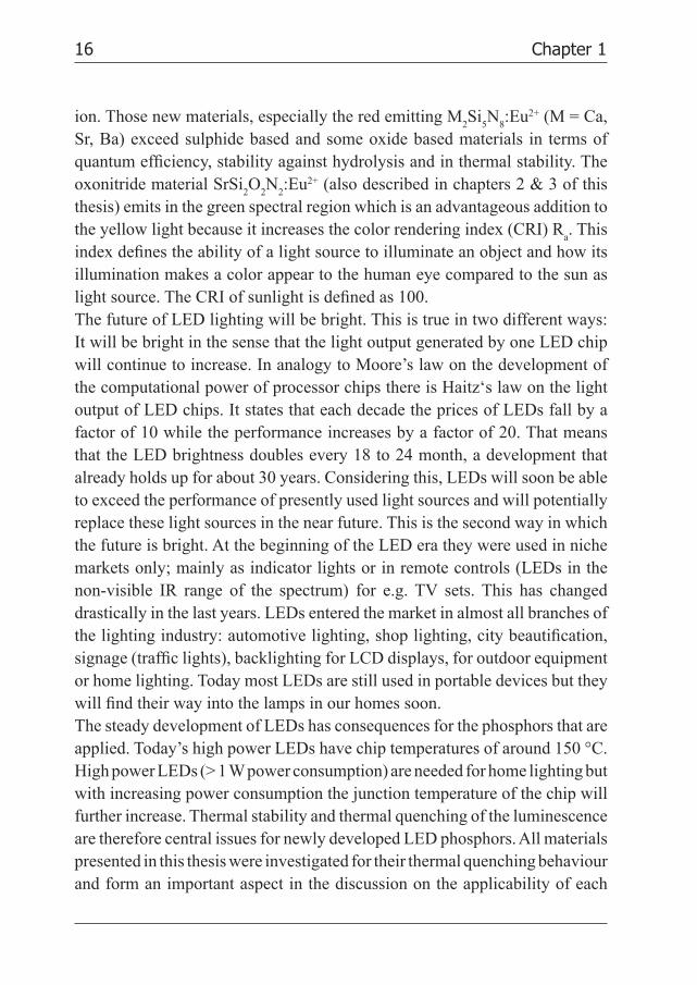
ion. Those new materials, especially the red emitting M2Si
5N
8:Eu2+ (M = Ca,
Sr, Ba) exceed sulphide based and some oxide based materials in terms of quantum effi ciency, stability against hydrolysis and in thermal stability. The oxonitride material SrSi
2O
2N
2:Eu2+ (also described in chapters 2 & 3 of this
thesis) emits in the green spectral region which is an advantageous addition to the yellow light because it increases the color rendering index (CRI) R
a. This
index defi nes the ability of a light source to illuminate an object and how its illumination makes a color appear to the human eye compared to the sun as light source. The CRI of sunlight is defi ned as 100. The future of LED lighting will be bright. This is true in two different ways: It will be bright in the sense that the light output generated by one LED chip will continue to increase. In analogy to Moore’s law on the development of the computational power of processor chips there is Haitz‘s law on the light output of LED chips. It states that each decade the prices of LEDs fall by a factor of 10 while the performance increases by a factor of 20. That means that the LED brightness doubles every 18 to 24 month, a development that already holds up for about 30 years. Considering this, LEDs will soon be able to exceed the performance of presently used light sources and will potentially replace these light sources in the near future. This is the second way in which the future is bright. At the beginning of the LED era they were used in niche markets only; mainly as indicator lights or in remote controls (LEDs in the non-visible IR range of the spectrum) for e.g. TV sets. This has changed drastically in the last years. LEDs entered the market in almost all branches of the lighting industry: automotive lighting, shop lighting, city beautifi cation, signage (traffi c lights), backlighting for LCD displays, for outdoor equipment or home lighting. Today most LEDs are still used in portable devices but they will fi nd their way into the lamps in our homes soon.The steady development of LEDs has consequences for the phosphors that are applied. Today’s high power LEDs have chip temperatures of around 150 °C. High power LEDs (> 1 W power consumption) are needed for home lighting but with increasing power consumption the junction temperature of the chip will further increase. Thermal stability and thermal quenching of the luminescence are therefore central issues for newly developed LED phosphors. All materials presented in this thesis were investigated for their thermal quenching behaviour and form an important aspect in the discussion on the applicability of each
17Chapter 1
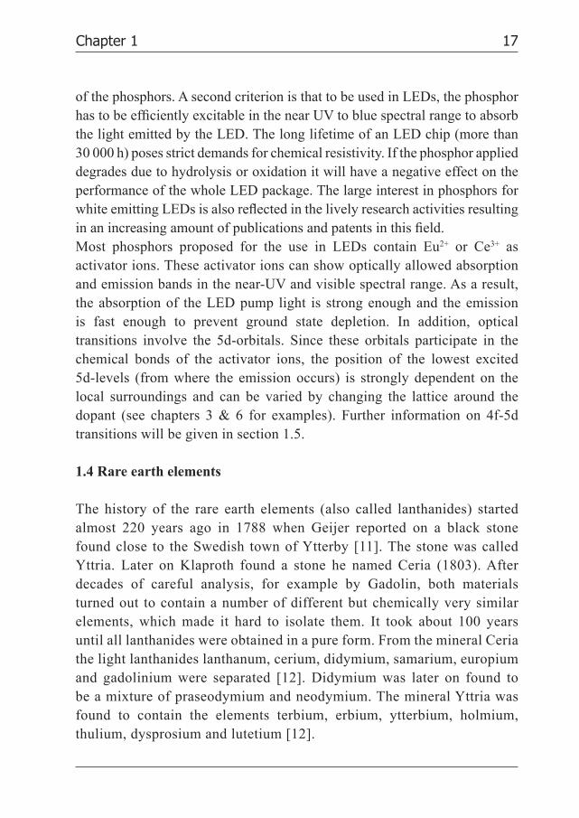
of the phosphors. A second criterion is that to be used in LEDs, the phosphor has to be effi ciently excitable in the near UV to blue spectral range to absorb the light emitted by the LED. The long lifetime of an LED chip (more than 30 000 h) poses strict demands for chemical resistivity. If the phosphor applied degrades due to hydrolysis or oxidation it will have a negative effect on the performance of the whole LED package. The large interest in phosphors for white emitting LEDs is also refl ected in the lively research activities resulting
in an increasing amount of publications and patents in this fi eld. Most phosphors proposed for the use in LEDs contain Eu2+ or Ce3+ as activator ions. These activator ions can show optically allowed absorption and emission bands in the near-UV and visible spectral range. As a result, the absorption of the LED pump light is strong enough and the emission is fast enough to prevent ground state depletion. In addition, optical transitions involve the 5d-orbitals. Since these orbitals participate in the chemical bonds of the activator ions, the position of the lowest excited 5d-levels (from where the emission occurs) is strongly dependent on the local surroundings and can be varied by changing the lattice around the dopant (see chapters 3 & 6 for examples). Further information on 4f-5d transitions will be given in section 1.5.
1.4 Rare earth elements
The history of the rare earth elements (also called lanthanides) started almost 220 years ago in 1788 when Geijer reported on a black stone found close to the Swedish town of Ytterby [11]. The stone was called Yttria. Later on Klaproth found a stone he named Ceria (1803). After decades of careful analysis, for example by Gadolin, both materials turned out to contain a number of different but chemically very similar elements, which made it hard to isolate them. It took about 100 years until all lanthanides were obtained in a pure form. From the mineral Ceria the light lanthanides lanthanum, cerium, didymium, samarium, europium and gadolinium were separated [12]. Didymium was later on found to be a mixture of praseodymium and neodymium. The mineral Yttria was found to contain the elements terbium, erbium, ytterbium, holmium, thulium, dysprosium and lutetium [12].
18 Chapter 1
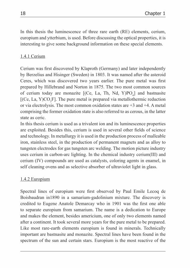
In this thesis the luminescence of three rare earth (RE) elements, cerium, europium and ytterbium, is used. Before discussing the optical properties, it is interesting to give some background information on these special elements.
1.4.1 Cerium
Cerium was fi rst discovered by Klaproth (Germany) and later independently by Berzelius and Hisinger (Sweden) in 1803. It was named after the asteroid Ceres, which was discovered two years earlier. The pure metal was fi rst prepared by Hillebrand and Norton in 1875. The two most common sources of cerium today are monazite [(Ce, La, Th, Nd, Y)PO
4] and bastnasite
[(Ce, La, Y)CO3F]. The pure metal is prepared via metallothermic reduction
or via electrolysis. The most common oxidation states are +3 and +4. A metal comprising the former oxidation state is also referred to as cerous, in the latter state as ceric.In this thesis cerium is used as a trivalent ion and its luminescence properties are exploited. Besides this, cerium is used in several other fi elds of science and technology. In metallurgy it is used in the production process of malleable iron, stainless steel, in the production of permanent magnets and as alloy to tungsten electrodes for gas tungsten arc welding. The motion picture industry uses cerium in carbon-arc lighting. In the chemical industry cerium(III) and cerium (IV) compounds are used as catalysts, coloring agents in enamel, in self cleaning ovens and as selective absorber of ultraviolet light in glass.
1.4.2 Europium
Spectral lines of europium were fi rst observed by Paul Emile Lecoq de Boisbaudran in1890 in a samarium-gadolinium mixture. The discovery is credited to Eugene Anatole Demarcay who in 1901 was the fi rst one able to separate europium from samarium. The name is a dedication to Europe and makes the element, besides americium, one of only two elements named after a continent. It took several more years for the pure metal to be prepared. Like most rare-earth elements europium is found in minerals. Technically important are bastnasite and monazite. Spectral lines have been found in the spectrum of the sun and certain stars. Europium is the most reactive of the

19Chapter 1
rare earth elements. It is found in the oxidation states +2 and +3, where the divalent ion is the more often occurring. This is in contrast to all the other rare earth ions, which are mostly stable as trivalent ion.The usage of divalent and trivalent europium is restricted in relation to its unique luminescence properties. Europium activated phosphors are used in cathode ray tubes, in fl uorescent tubes, in scintillators, as safeguard feature in
banknotes [13], and in markers for a variety of medical applications. For further
information the reader is referred to the review article by Jüstel et al. [14].
1.4.3 Ytterbium
It took until 1878 that the Swiss chemist Galissard de Marignac was able
to separate an element he called ytterbia. Only in 1937 for the fi rst time the
pure metal was prepared by Klemm and Bonner. The metals quality was not
good enough to determine chemical and physical properties. A pure enough
material allowing a more extensive characterization was made in 1953.
Ytterbium is found in minerals as part of a mixture of rare earths. The minerals
monazite, euxenite and xenotime comprise small amounts of this element. In
these compounds ytterbium is mainly found having the oxidation state +3.
Only few materials containing divalent ytterbium are known. This thesis will
present two new Yb2+ containing materials.
Ytterbium can be used to improve the mechanical properties of stainless
steel. It is part of alloys which are used as high quality permanent magnets.
The isotope 169Yb is a rarely used source for γ-radiation in nuclear medicine.
Ytterbium(III)fl uoride is used in dental applications to increase contrast for
x-ray images and to improve the caries protection due to the constant release
of fl uoride. In combination with other RE ions it can show upconversion (for
examples with Ho3+ [15], Tm3+ [16] and Er3+ [17] as co-dopants) and is able
to convert infrared radiation into visible light.
1.5 4f-5d luminescence
Lanthanide ions are well known for their effi cient luminescence due to
intraconfi gurational 4fn transitions. The luminescence from the lanthanides
discussed in this thesis is of a different origin. All three lanthanide ions show
20 Chapter 1
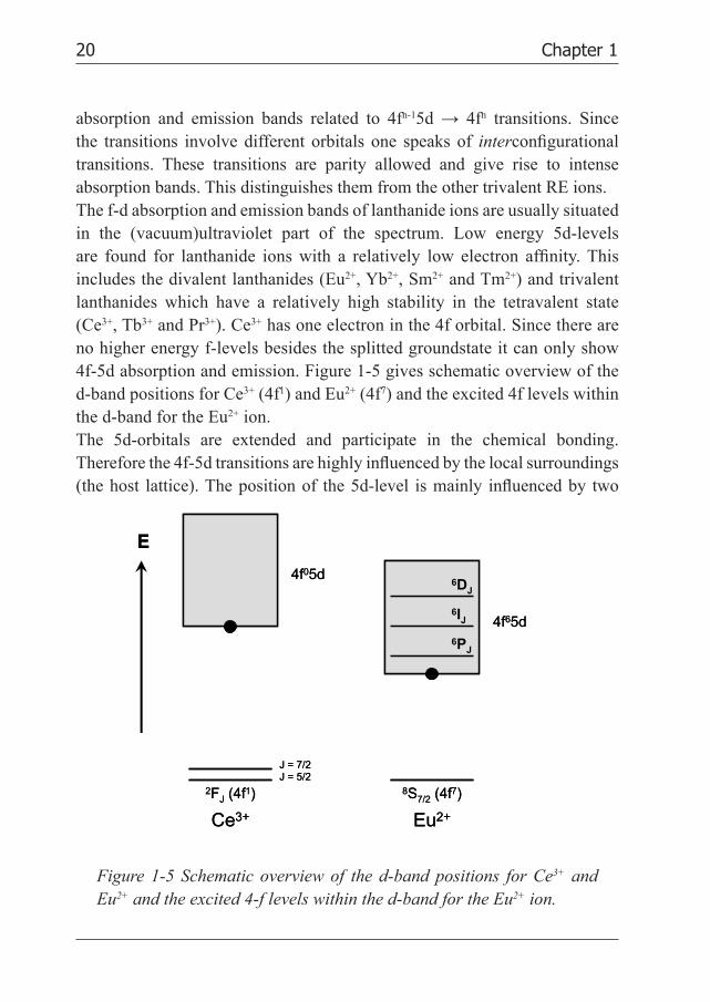
absorption and emission bands related to 4fn-15d → 4fn transitions. Since the transitions involve different orbitals one speaks of interconfi gurational transitions. These transitions are parity allowed and give rise to intense absorption bands. This distinguishes them from the other trivalent RE ions. The f-d absorption and emission bands of lanthanide ions are usually situated in the (vacuum)ultraviolet part of the spectrum. Low energy 5d-levels are found for lanthanide ions with a relatively low electron affi nity. This includes the divalent lanthanides (Eu2+, Yb2+, Sm2+ and Tm2+) and trivalent lanthanides which have a relatively high stability in the tetravalent state (Ce3+, Tb3+ and Pr3+). Ce3+ has one electron in the 4f orbital. Since there are no higher energy f-levels besides the splitted groundstate it can only show 4f-5d absorption and emission. Figure 1-5 gives schematic overview of the d-band positions for Ce3+ (4f1) and Eu2+ (4f7) and the excited 4f levels within the d-band for the Eu2+ ion.The 5d-orbitals are extended and participate in the chemical bonding. Therefore the 4f-5d transitions are highly infl uenced by the local surroundings (the host lattice). The position of the 5d-level is mainly infl uenced by two
E
Ce3+ Eu2+
6PJ
6IJ
6DJ
4f65d
4f05d
8S7/2 (4f7)2FJ (4f1)
J = 7/2J = 5/2
E
Ce3+ Eu2+
6PJ
6IJ
6DJ
4f65d
4f05d
8S7/2 (4f7)2FJ (4f1)
J = 7/2J = 5/2
Figure 1-5 Schematic overview of the d-band positions for Ce3+ and
Eu2+ and the excited 4-f levels within the d-band for the Eu2+ ion.
21Chapter 1
factors: the nephelauxetic effect and the crystal fi eld splitting [18]. The word nephelauxetic stands for (electron) cloud expanding. It can be understood considering the covalency between two atoms. For materials like rock salt the difference in electronegativity (EN) is large and the material has ionic atom bonding. The electrons reside on either Cl- or the Na+ ions. Bonds between the same elements, e.g. H
2, involve atoms with identical EN and the
bond is covalent. The electron cloud is shared between the two atoms. For a decreasing EN difference in the bonding between two different atoms the covalence increases. As the covalency of the bonding with the surrounding ligands increases, the energy for the 5d state of the lanthanide shifts to lower energy, while the 5d electron is more delocalized (nephelauxetic effect) over the ligands as a result of the covalent bonding. The shift involves the barycenter of the 5d state (the average energy of all crystal fi eld components). The crystal fi eld splitting can be understood by considering the static electric fi eld resulting from the charged ligands surrounding the lanthanide ion (although a better understanding can be obtained from a molecular orbital diagram). Replacing O2- by N3- results in a higher formal charge of the ligands and will increase the crystal fi eld splitting. This will result in a lowering of the lowest emitting d-level and shift the d-f emission to longer wavelengths. As an example, the oxide Ba
2SiO
4:Eu2+ shows green emission [19] while the nitride
Ba2Si
5N
8:Eu2+ shows red emission [10]. Additionally, an energy difference is
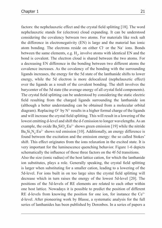
found between the excitation and the emission energy: the so called Stokes’ shift. This effect originates from the ions relaxation in the excited state. It is very important for the luminescence quenching behavior. Figure 1-6 depicts schematically the infl uence of those three factors on the 4f-5d transitions.Also the size (ionic radius) of the host lattice cation, for which the lanthanide ion substitutes, plays a role. Generally speaking, the crystal fi eld splitting is larger when substituting for a smaller cation, leading to a lowering of the 5d-level. For ions built in on too large sites the crystal fi eld splitting will decrease which in turn raises the energy of the lowest 5d-level [20]. The positions of the 5d-levels of RE elements are related to each other within one host lattice. Nowadays it is possible to predict the position of different RE d-levels from knowing the position for one ion, for instance the Ce3+ d-level. After pioneering work by Blasse, a systematic analysis for the full series of lanthanides has been published by Dorenbos. In a series of papers a
22 Chapter 1
comprehensive analysis of the f-d luminescence properties of the divalent and trivalent lanthanides is given [21].Important for the use of RE elements is also their luminescence decay time. For the 5d-4f emission of Ce3+, Eu2+ and Yb2+ it was found that decay times differ by several orders of magnitude. For Ce3+ typical decay times are in the ns range [22], for Eu2+ in the µs range [23] and for Yb2+ in the ms range [24]. Poort et al. established a dependence of the decay time of Eu2+ on the position of the emission band [25]. The position of the 5d-levels for other trivalent RE ions except Ce3+ are mainly in the VUV range of the electromagnetic spectrum. They are not investigated in this thesis. The interested reader is referred to the work of van Pieterson [26].
1.6 Summary
This thesis can be divided into two different parts. Part one comprises chapters 2, 3 and 4 which are on oxonitridosilicate (sion) and aluminooxonitridosilicate (sialon) materials doped each with Eu2+ or Yb2+.
5d
4f
nephela
uxetic
eff
ect
cryst
al field
sp
litting
Sto
kes
shift
free ion
E
exci
tati
on
emis
sio
n
5d
4f
nephela
uxetic
eff
ect
cryst
al field
sp
litting
Sto
kes
shift
free ion
E
exci
tati
on
emis
sio
n
Figure 1-6 The infl uence of nephelauxetic effect, crystal fi eld splitting
and Stokes shift on the 4f-5d transition of the free ion.

23Chapter 1
Part two comprises chapters 5 and 6 which are on Yttrium Aluminum Garnet (YAG) doped with Ce3+ and/or Gd3+.In chapter 2 the optical properties of SrSi
2O
2N
2 doped with divalent Eu2+ and
Yb2+ are investigated. The Eu2+ doped material shows effi cient green emission peaking at around 540 nm that is consistent with 4f 65d→4f 7 transitions of Eu2+. Due to the high quantum yield (90%) and high quenching temperature (>500 K) of the luminescence SrSi
2O
2N
2:Eu2+ is a promising material for
application in phosphor converted LEDs. The Yb2+ luminescence is markedly different from Eu2+ and is characterized by a larger Stokes’ shift and a lower quenching temperature. The anomalous luminescence properties are ascribed to impurity trapped exciton emission. Based on temperature and time dependent luminescence measurements, a schematic energy level diagram is derived for both Eu2+ and Yb2+ relative to the valence and conduction bands of the oxonitridosilicate host material.Chapter 3 describes the possibilities of color tuning of the LED phosphor Sr
1-x-y-zCa
xBa
ySi
2O
2N
2:Eu
z2+ (0 ≤ x, y ≤ 1; 0.005 ≤ z ≤ 0.16). The emission
color can be tuned in two ways: by changing the Eu2+ concentration and by substitution of the host lattice cation Sr2+ by either Ca2+ or Ba2+. The variation of the Eu2+ concentration shows a red shift of the emission upon increasing the Eu-concentration above 2%. The red shift is explained by energy migration and energy transfer to Eu2+ ions emitting at longer wavelengths. Along with this (desired) red shift there is an (undesired) lowering of the quantum effi ciency and the thermal quenching temperature due to concentration quenching. Partial substitution of Sr2+ by either Ca2+ or Ba2+ also results in a red shifted Eu2+ emission. For Ca2+ this is expected and the red shift is explained by an increased crystal fi eld splitting for Eu2+ on the (smaller) Ca2+ cation site. For Ba2+ the red shift is surprising. Often, a blue shift of the fd emission is observed in case of substitution of Sr2+ by the larger Ba2+ cation. The Eu2+ emission in the pure BaSi
2O
2N
2 host lattice is indeed blue shifted.
Temperature dependent luminescence measurements show that the quenching temperature drops upon substitution of Sr by Ca, while for Ba substitution the quenching temperature remains high. Color tuning by partial substitution of Sr2+ by Ba2+ is therefore the most promising way to shift the color point of LEDs while retaining a high relative quantum yield and high luminescence quenching temperature.
24 Chapter 1
To conclude the fi rst part of this thesis chapter 4 investigates the optical properties of SrSi
2AlO
2N
3 doped with Eu2+ and Yb2+ for a potential application
in LEDs. The Eu2+ doped material shows emission in the green, peaking around 500 nm. The emission is ascribed to the 4f65d1 to 4f7 transition on Eu2+. In view of the too low quantum effi ciency and the thermal quenching temperature around the operation temperature of high power LEDs the phosphor is less suitable for the use in phosphor converted LEDs. The Yb2+ emission shows the same anomalously red-shifted emission compared to the one of Eu2+, as reported in chapter 2, which is characterized by a larger FWHM, a larger Stokes’ Shift and lower thermal quenching temperature as well. The emission is ascribed to self-trapped exciton emission. The Yb2+ activated phosphor is found to be unsuitable for use in phosphor converted LEDs.The second part of this thesis is on YAG doped with gadolinium and/or cerium. In chapter 5 we report on the luminescence temperature quenching in YAG:Ce. For a wide range of Ce-concentrations (between 0.033% and 3.3%) the temperature dependence of the emission intensity and the luminescence life times are reported. The intrinsic quenching temperature of the Ce-luminescence is shown to be very high (>680 K). The lower quenching temperatures reported in the literature are explained by thermally activated concentration quenching (for highly doped systems) and the temperature dependence of the oscillator strength (for low doping concentrations). In addition, high resolution spectra are reported which provide insight in the position of the zero-phonon transition (20 450 cm-1), the Stokes’ shift (2400 cm-1), the energy of the dominant phonon mode (200 cm-1) and the Huang-Rhys parameter (S=6). These parameters can serve as input for comparison with ab initio calculations on the position of and relaxation in the excited 5d state of Ce3+ in YAG.Finishing this thesis, for the widely applied white light LED-phosphor Y
3Al
5O
12:Ce (YAG:Ce) the infl uence of partial substitution of Y by Gd on the
Ce3+ luminescence and temperature quenching is reported in chapter 6. Low Ce-doping concentrations (0.03 and 0.3%) are used to avoid concentration quenching or radiative reabsorption. The luminescence shows a pronounced redshift from 536 nm (for YAG:Ce) to 579 nm (for Y
0.25Gd
0.75Al
5O
12:Ce)
while the quenching temperature decreases. The results are explained by an

25Chapter 1
increase in the crystal fi eld splitting and Stokes’ shift upon substitution of Y3+ by Gd3+ ions in the YAG host lattice. In spite of the lower luminescence quenching temperature, (Y,Gd)AG:Ce is a promising phosphor for realizing white light LEDs with a lower color temperature.
References
1 A. Žukauskas, M.S. Shur, R. Gaska, Introduction to Solid-State Lighting, Wiley-
Interscience Publication (2002) chapter 4.
2 T.A. Edison, U.S. patent No. 223,898 of 1879.
3 A. Just, F. Hanaman, German patent No. 154,262 of 1903.
4 H.J. Round “A note on Carborundum” Electrical World 49 (6) (1907) 309.
5 N. Holonyak Jr., S.F. Bevacqua, Appl. Phys. Lett. 1 (4) (1962) 82.
6 S. Nakamura, Jpn. J. Appl. Phys. 30 (1991) L1705.
7 S. Nakamura, G. Fasol, The blue Laser Diode: GaN Based Light Emitters and Lasers,
(Springer, Berlin) (1997) 343.
8 P. Schlotter, J. Baur, Ch. Hielscher, M. Kunzer, H. Obloh, R. Schmidt, J. Schneider,
Mater. Sci. Eng. B 59 (1999) 390.
9 Y. Hu, W. Zhuang, H. Ye, S. Zhang, Y. Fang, X. Huang, J. Lumin. 111 (2005) 139.
10 R. Mueller-Mach, G. Mueller, M.R. Krames, H.A. Höppe, F. Stadler, W. Schnick,
T. Juestel, P. Schmidt, phys. stat. sol. (a) 202 (2005) 1721.
11 B. Geijer, Annalen für die Freunde der Naturlehre 9 (1788) 229.
12 W.H. Brock, The Norton History of Chemistry (1st ed. W.W. Norton & Company, 1993).
13 F. Suyver and A. Meijerink, Chemisch2Weekblad 98 (2002) 12.
14 T. Jüstel, H. Nikol, C. Ronda, Angew. Chem. Int. Ed. 37 (1998) 3084.
15 X. Luo, W. Cao, Mater. Lett. 61(17) (2007) 3696.
16 W. Xu, X. Xu, F. Wu, G. Zhao, Z. Zhao, G. Zhou, J. Xu, Opt. Commun. 272(1) (2007) 182.
17 Y. Wei, F. Lu, X. Zhang, D. Chen, Mater. Lett. 61(6) (2007) 1337.
18 G. Blasse, A. Bril, Philips Tech. Rev. 31 (1970) 303.
19 J.S. Kim, Y.H. Park, S.M. Kim, J.C. Choi, H.L. Park, Solid State Commun. 133(7) (2005) 445.
20 G. Blasse, B.C. Grabmaier, Luminescent materials (1994) Springer Verlag, Berlin.
21 P. Dorenbos, J. Lumin. 91 (2000) 155 and P. Dorenbos, J. Lumin. 104 (2003) 239.
22 G. Blasse, A. Bril, Appl. Phys. Lett. 11(2) (1967) 53.
23 T. Hoshina, J. Phys. Soc. Japan 48 (1980) 1261.
24 S. Lizzo, A. Meijerink, G. Blasse, J. Lumin. 59 (1994) 185.

26 Chapter 1
25 S.H.M. Poort, A. Meijerink, G. Blasse, J. Phys. Chem. Solids, 58(9) (1997) 1451.
26 L. van Pieterson, Proefschrift Universiteit Utrecht, 2001.