Embed Size (px)
Citation preview
CHAPTER - IX ARTIFICIAL GROUND WATER RECHARGE
81
CHAPTER - IX
ARTIFICIAL GROUND WATER RECHARGE 9.0 WHY ARTIFICIAL RECHARGE Average annual water resources in our river basins are estimated as 1,869 billion cubic metres (BCM) of which utilizable resources are of the order of 1,086 BCM. Out of this, 690 BCM is available as surface water and the remaining 396 BCM as ground water. The source of all this water is rain or snow. The huge ground water storage of 396 BCM is the result of rain and snowmelt water percolating through various layers of soil and rocks. However, the amount of percolation varies greatly from region to region and within the same region from place to place depending upon the amount and pattern of rainfall (i.e. number and duration of rainy days, rainfall amount and intensity), characteristics of soils and rocks (i.e. porosity, cracks and loose joints in rocks etc.), the nature of terrain (i.e. hills, plateaus, plains, valleys etc.), and other climatic factors like temperature and humidity. As a result, availability of water from sub-surface storages varies considerably from place to place. In most low rainfall areas of the country the availability of utilizable surface water is so low that people have to depend largely on ground water for agriculture and domestic use. Excessive ground water pumping in these areas, especially in some of the 91 drought prone districts in 13 states, has resulted in alarming lowering of the ground water levels. The problem has been further compounded due to large-scale urbanization and growth of mega cities, which has drastically reduced open lands for natural recharge. In hard rock areas there are large variations in ground water availability even from village to village. In order to improve the ground water situation it is necessary to artificially recharge the depleted ground water aquifers. The available techniques are easy, cost-effective and sustainable in the long term. Many of these can be adopted by the individuals and village communities with locally available materials and manpower. 9.1 ADVANTAGES OF ARTIFICIAL RECHARGE Following are the main advantages of artificially recharging the ground water aquifers. • No large storage structures needed to store water. Structures required are small and
cost-effective • Enhance the dependable yield of wells and hand pumps • Negligible losses as compared to losses in surface storages • Improved water quality due to dilution of harmful chemicals/ salts • No adverse effects like inundation of large surface areas and loss of crops • No displacement of local population • Reduction in cost of energy for lifting water especially where rise in ground water
level is substantial • Utilizes the surplus surface runoff which otherwise drains off
82
9.2 IDENTIFICATION OF AREAS FOR RECHARGE The first step in planning a recharge scheme is to demarcate the area of recharge. Such an area should, as far as possible, be a micro-watershed (2,000-4,000 ha) or a mini-watershed (40-50 ha). However, localized schemes can also be taken up for the benefit of a single hamlet or a village. In either case the demarcation of area should be based on the following broad criteria: • Where ground water levels are declining due to over-exploitation • Where substantial part of the aquifer has already been desaturated i.e. regeneration of
water in wells and hand pumps is slow after some water has been drawn • Where availability of water from wells and hand pumps is inadequate during the lean
months • Where ground water quality is poor and there is no alternative source of water 9.3 SOURCES OF WATER FOR RECHARGE Before undertaking a recharge scheme, it is important to first assess the availability of adequate water for recharge. Following are the main sources, which need to be identified and assessed for adequacy: • Precipitation (rainfall) over the demarcated area • Large roof areas from where rainwater can be collected and diverted for recharge • Canals from large reservoirs from which water can be made available for recharge • Natural streams from which surplus water can be diverted for recharge, without
violating the rights of other users • Properly treated municipal and industrial wastewaters. This water should be used only
after ascertaining its quality “In situ” precipitation is available at every location but may or may not be adequate for the recharge purposes. In such cases water from other sources may be transmitted to the recharge site. Assessment of the available sources of water would require consideration of the following factors: • Available quantity of water • Time for which the water would be available • Quality of water and the pretreatment required • Conveyance system required to bring the water to the recharge site 9.4 INFILTRATION CAPACITY OF SOIL Infiltration capacity of soil is an important factor that governs the rate of saturation of the vadose zone and thereby the efficacy or otherwise of a recharge scheme. Infiltration capacity of different soil types are done by field-tests by State Agriculture Departments and/ or the Land Use Survey Organizations. This data/ information together with maps showing infiltration rates is usually available in their departmental reports published periodically and
83
are available with the District Agriculture Officer. At the district level, this information is available in the departmental reports of the Central and State Ground Water Boards. Aquifer Suitability This depends mainly on storage coefficient, availability of storage space and permeability. Very high permeability results in loss of recharged water due to sub-surface drainage where as low permeability reduces recharge rate. In order to have good recharge rate and to retain the recharged water for sufficient period for its use during lean period, moderate permeability is needed. Older alluvium, buried channels, alluvial fans, dune sands, glacial outwash etc. are the favourable places for recharge. In hard rock areas, fractured, weathered and cavernous rocks are capable of allowing high intake of water. The basaltic rocks i.e. those formed by lava flows, usually have large local pockets, which can take recharge water. 9.5 HYDRO-METEOROLOGICAL STUDIES These studies are undertaken to understand the rainfall pattern and evaporation losses and thereby to determine the amount of water that would be available from a given catchment and the size of storages to be built. The main factors to be considered are: • Minimum annual rainfall during the previous 10 years • Number of rainy spells in a rainy season and duration of each spell • Amount of rainfall in each rainy spell • Rainfall intensity (maximum) 3 hourly, 6 hourly etc. as may be relevant for a region.
As a general guide, the one, which causes significant runoff and local flooding, should be adopted.
This information/ data is usually readily available in District Statistical Reports published by the District Statistical Organisation. However, the most important source is the India Meteorological Department. For the purpose of rainwater harvesting only readily available secondary data is adequate. The alternative sources of this data are the reports of major, medium or minor irrigation projects, which have been recently completed in the region or are under construction or are planned. 9.6 HYDROGEOLOGICAL STUDIES A detailed hydrogeological study of the project area and also the regional picture of hydrogeological setting is necessary to know precisely the promising locations for recharge and the type of structures to be built for the purpose. The aspects to be considered for a recharge scheme are: • Detailed information and maps showing
- Hydrogeological units demarcated on the basis of their water bearing capabilities at both shallow and deeper levels
- Ground water contours to determine the form of the water table and hydraulic connection of ground water with rivers, canals etc.
- Depth to water table (Maximum, Minimum and Mean)
84
- Amplitude of water level fluctuations - Piezometric head in deeper aquifers and their variation with time - Ground water potential of different hydrogeological units and the level of
ground water development - Chemical quality of water in different aquifers
This information is usually available in district-wise ground water reports prepared by the Central Ground Water Board and/ or the State Ground Water Board.
• Information from local open wells
Artificial recharge schemes are site-specific and even the replication of the proven techniques are to be based on the local hydrogeological and hydrological conditions. However, following information from local wells needs to be taken into consideration in planning such schemes:
- The unsaturated thickness of rock formations occurring beyond 3 metres
below ground level should be considered to assess the requirement of water to build up the sub-surface storage. The ground water recharge process should aim at saturating this entire unsaturated zone (also know as vadose zone)
- The upper 3 m of the unsaturated zone should not be considered for recharging since it may cause adverse environmental impacts like water logging, soil salinity etc.
- The post-monsoon depth to water level represents a situation of minimum thickness of vadose zone available for recharge. This should be considered vis-à-vis the available surplus runoff in the area
9.7 GEOPHYSICAL STUDIES These studies are expensive and time consuming and require high levels of skill and sophisticated equipment. These are, therefore, economically viable for large ground water development projects and are not suitable for small artificial recharge schemes at local/ village level. The main purpose of applying geophysical methods for the selection of appropriate site for artificial recharge studies is to assess the unknown sub-surface hydrogeological conditions economically, adequately and unambiguously. Generally the prime task is to compliment the exploratory programme. Mostly it is employed to narrow down the target zone, pinpoint the probable site for artificial recharge structure and its proper design. Nevertheless, the application of geophysical methods is to bring out a comparative picture of the sub-surface litho environment, surface manifestation of such structures and correlate them with the hydrogeological setting. Besides defining the sub-surface structure and lithology, it can identify the brackish/ fresh ground water interface, contaminated zone (saline) and the area prone to seawater intrusion.
85
Using certain common geophysical methods, it is possible to model the • Stratification of aquifer system and spatial variability of hydraulic conductivity of the
characteristic zone, suitable for artificial recharge • Negative or non-productive zones of low hydraulic conductivity in unsaturated and
saturated zones • Vertical hydraulic conductivity discontinuities, such as dyke and fault zone • Moisture movement and infiltration capacity of the unsaturated zone • Direction of ground water flow under natural/ artificial recharge processes • Salinity ingress, trend and short duration depth salinity changes in the aquifers due to
varied abstraction or recharge The application of proper techniques, plan of survey and suitable instruments can yield better understandable results, but, of indirect nature. 9.8 QUALITY OF SOURCE WATER Chemicals and Salts Problems which arise as a result of recharge to ground water are mainly related to the quality of raw waters that are available for recharge and which generally require some sort of treatment before being used in recharge installations. They are also related to the changes in the soil structure and the biological phenomena, which take place when infiltration begins, thereby causing environmental concerns. The chemical and bacteriological analysis of source water and that of ground water is therefore essential. Sediment Load A major requirement for waters that are to be used in recharge projects is that they be silt-free. Silt may be defined as the content of undissolved solid matter, usually measured in mg/l, which settles in stagnant water or in flowing water with velocities, which do not exceed 0.1 m/hr. 9.9 PREVENTION OF CLOGGING OF SOIL PORES This is one of the important considerations in planning an artificial recharge scheme. The usual methods to minimize the clogging are: • Periodical removing of the mud-cake and dicing or scraping of the surface layer • Installation of a filter on the surface, the permeability of which is lower than that of
the natural strata (the filter must be removed and renewed periodically) • Addition of organic matter or chemicals to the uppermost layer • Cultivation of certain plant-covers, notably certain kinds of grass • Providing inverted filter consisting of fine sand, coarse sand and gravel at the bottom
of infiltration pits/ trenches are very effective
86
Clogging by biological activity depends upon the mineralogical and organic composition of the water and basin floor and upon the grain-size and permeability of the floor. The only feasible method of treatment developed so far consists in thoroughly drying the ground under the basin. 9.10 METHODS OF ARTIFICIAL RECHARGE These can be broadly classified as: • Spreading Method
- Spreading within channel - Spreading stream water through a network of ditches and furrows - Ponding over large area
(a) Along stream channel viz. Check Dams/ Nala Bunds (b) Vast open terrain of a drainage basin viz. Percolation Tanks (c) Modification of village tanks as recharge structures.
• Recharge Shafts - Vertical Shafts - Lateral Shafts
• Injection Wells • Induced Recharge • Improved Land and Watershed Management
- Contour Bunding - Contour Trenching - Bench Terracing - Gully Plugging
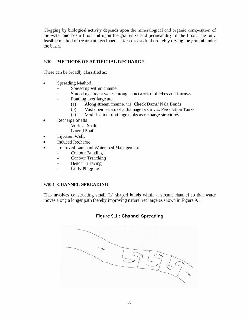
9.10.1 CHANNEL SPREADING This involves constructing small ‘L’ shaped bunds within a stream channel so that water moves along a longer path thereby improving natural recharge as shown in Figure 9.1.
Figure 9.1 : Channel Spreading
87
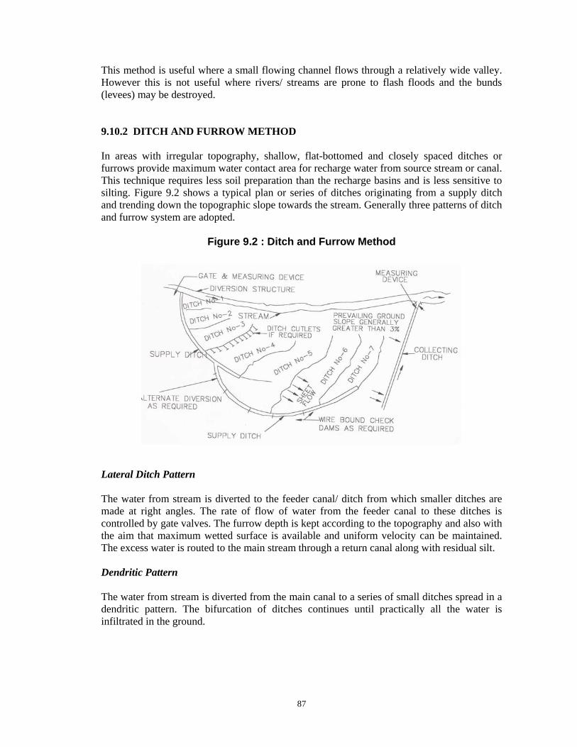
This method is useful where a small flowing channel flows through a relatively wide valley. However this is not useful where rivers/ streams are prone to flash floods and the bunds (levees) may be destroyed. 9.10.2 DITCH AND FURROW METHOD In areas with irregular topography, shallow, flat-bottomed and closely spaced ditches or furrows provide maximum water contact area for recharge water from source stream or canal. This technique requires less soil preparation than the recharge basins and is less sensitive to silting. Figure 9.2 shows a typical plan or series of ditches originating from a supply ditch and trending down the topographic slope towards the stream. Generally three patterns of ditch and furrow system are adopted.
Figure 9.2 : Ditch and Furrow Method Lateral Ditch Pattern The water from stream is diverted to the feeder canal/ ditch from which smaller ditches are made at right angles. The rate of flow of water from the feeder canal to these ditches is controlled by gate valves. The furrow depth is kept according to the topography and also with the aim that maximum wetted surface is available and uniform velocity can be maintained. The excess water is routed to the main stream through a return canal along with residual silt. Dendritic Pattern The water from stream is diverted from the main canal to a series of small ditches spread in a dendritic pattern. The bifurcation of ditches continues until practically all the water is infiltrated in the ground.
88
Contour Pattern The ditches are excavated following the ground surface contour of the area. When the ditch comes closer to the stream a switchback is made and thus the ditch is made to meander back and forth repeatedly. At a lowest point downstream, the ditch joins the main stream, thus returning the excess water to it. Site Characteristics and Design Guidelines (i) Although this method is adaptable to irregular terrain, the water contact area seldom
exceeds 10 percent of the total recharge area. (ii) Ditches should have slope to maintain flow velocity and minimum deposition of
sediments. (iii) Ditches should be shallow, flat-bottomed, and closely spaced to obtain maximum
water contact area. Width of 0.3 to 1.8 m is typical. (iv) A collecting ditch to convey the excess water back to the mainstream channel should
be provided. Ditch and furrow method is usually costly since it requires high level of supervision and maintenance. 9.10.3 CHECK DAMS/ NALA BUNDS As discussed in Chapter-VI, these provide not only channel storage but also augment ground water recharge. 9.10.4 PERCOLATION TANKS (PT)/ SPREADING BASIN As discussed in Chapter-VI, these are the most prevalent structures in India to recharge the ground water reservoir both in alluvial as well as hard rock formations. The efficacy and feasibility of these structures is more in hard rock formation where the rocks are highly fractured and weathered. In the States of Maharashtra, Andhra Pradesh, Madhya Pradesh, Karnataka and Gujarat, the percolation tanks have been constructed in basaltic lava flows and crystalline rocks. The percolation tanks are however also feasible in mountain fronts occupied by talus scree deposits. These are found to be very effective in Satpura Mountain front area in Maharashtra. The percolation tanks can also be constructed in the Bhabar zone. Percolation tanks with wells and shafts are also constructed to recharge deeper aquifers where shallow or superficial formations are highly impermeable or clayey. 9.10.5 MODIFICATION OF VILLAGE TANKS AS RECHARGE STRUCTURES The existing village tanks, which are often silted up or damaged, can be modified to serve as recharge structure. In general no “Cut Off Trench” (COT) and Waste Weir is provided for village tanks. A village tanks can be converted into a recharge structure by desilting its bed and providing a COT on the upstream end of the bund. Several such tanks are available which can be modified for enhancing ground water recharge. Some of the tanks in Maharashtra and Karnataka have been converted.
89
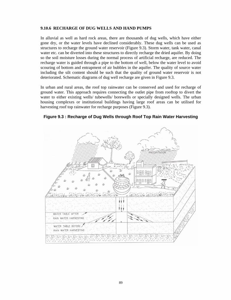
9.10.6 RECHARGE OF DUG WELLS AND HAND PUMPS In alluvial as well as hard rock areas, there are thousands of dug wells, which have either gone dry, or the water levels have declined considerably. These dug wells can be used as structures to recharge the ground water reservoir (Figure 9.3). Storm water, tank water, canal water etc. can be diverted into these structures to directly recharge the dried aquifer. By doing so the soil moisture losses during the normal process of artificial recharge, are reduced. The recharge water is guided through a pipe to the bottom of well, below the water level to avoid scouring of bottom and entrapment of air bubbles in the aquifer. The quality of source water including the silt content should be such that the quality of ground water reservoir is not deteriorated. Schematic diagrams of dug well recharge are given in Figure 9.3. In urban and rural areas, the roof top rainwater can be conserved and used for recharge of ground water. This approach requires connecting the outlet pipe from rooftop to divert the water to either existing wells/ tubewells/ borewells or specially designed wells. The urban housing complexes or institutional buildings having large roof areas can be utilised for harvesting roof top rainwater for recharge purposes (Figure 9.3).
Figure 9.3 : Recharge of Dug Wells through Roof Top Rain Water Harvesting
90
9.10.7 RECHARGE SHAFT These are the most efficient and cost effective structures to recharge the aquifer directly. These can be constructed in areas where source of water is available either for some time or perennially. Following are the site characteristics and design guidelines: (i) To be dug manually if the strata is of non-caving nature. (ii) If the strata is caving, proper permeable lining in the form of open work, boulder
lining should be provided. (iii) The diameter of shaft should normally be more than 2 m to accommodate more water
and to avoid eddies in the well. (iv) In the areas where source water is having silt, the shaft should be filled with boulder,
gravel and sand to form an inverted filter. The upper-most sandy layer has to be removed and cleaned periodically. A filter should also be provided before the source water enters the shaft.
(v) When water is put into the recharge shaft directly through pipes, air bubbles are also sucked into the shaft through the pipe, which can choke the aquifer. The injection pipe should therefore be lowered below the water level.
The main advantages of this technique are as follows: • It does not require acquisition of large piece of land as in case of percolation tanks. • There are practically no losses of water in the form of soil moisture and evaporation,
which normally occur when the source water has to traverse the vadose zone. • Disused or even operational dugwells can be converted into recharge shafts, which
does not involve additional investment for recharge structure. • Technology and design of the recharge shaft is simple and can be applied even where
base flow is available for a limited period. • The recharge is fast and immediately delivers the benefit. In highly permeable
formations, the recharge shafts are comparable to percolation tanks. The recharge shafts can be constructed in two different ways viz. vertical and lateral. The details of each are given in the following paragraphs. 9.10.8 VERTICAL RECHARGE SHAFT The vertical recharge shaft can be provided with or without injection well at the bottom of the shaft. Without Injection well • Ideally suited for deep water levels (up to 15 m bgl). • Presence of clay is encountered within 15 m. • Effective in the areas of less vertical natural recharge. • Copious water available can be effectively recharged. • Effective with silt water also (using inverted filter consisting of layers of sand, gravel
and boulder).
91
• Depth and diameter depends upon the depth of aquifer and volume of water to be recharged.
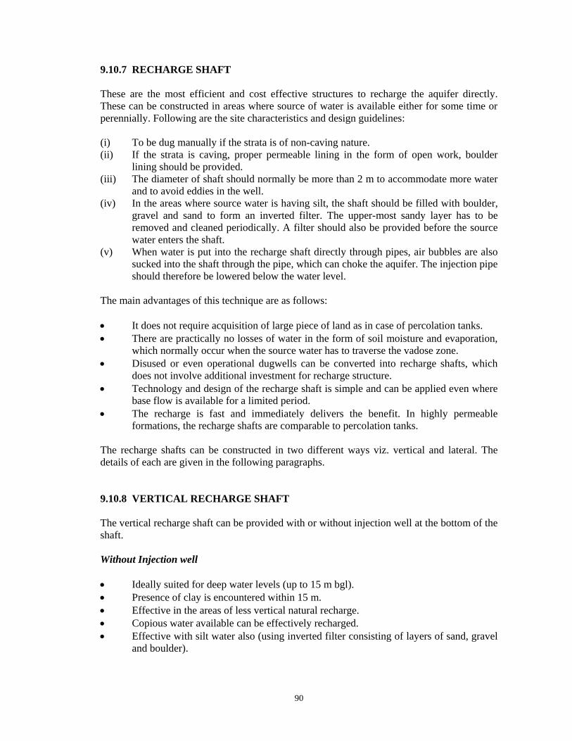
• The rate of recharge depends on the aquifer material and silt content in the water. • The rate of recharge with inverted filter ranges from 7-14 lps for 2-3 m diameter. This type of shaft has been constructed at the following places and is shown in Figure 9.4. • Brahm Sarovar, Kurukshetra district, Haryana - silt free water • Dhuri drain, Sangrur district, Punjab - surface runoff with heavy silt • Dhuri link drain, Sangrur district, Punjab - surface runoff with heavy silt • President Estate, New Delhi - roof top and surface runoff • Nurmahal block, Jalandhar district, Punjab • Kirmich and Samastipur, Kurukshetra district - surface water from depression
Figure 9.4 : Vertical Recharge Shaft Without Injection Well With Injection Well In this technique an injection well of 100-150 mm diameter is constructed at the bottom of the shaft piercing through the layers of impermeable horizon to the potential aquifers to be reached about 3 to l5 m below the water level (Figure 9.5). • Ideally suitable for very deep water level (more than 15 m) • Aquifer is overlain by impervious thick clay beds • Injection well can be with or without assembly • The injection well with assembly should have screen in the potential aquifer at least 3-
5 m below the water level • The injection well without assembly is filled with gravel to provide hydraulic
continuity so that water is directly recharged into the aquifer • The injection well without assembly is very cost effective • Depending upon volume of water to be injected, number of injection wells, can be
increased to enhance the recharge rate • The efficiency is very high and rate of recharge goes even up to 15 lps at certain
places

92
These structures have been constructed at following places: • Injection Well Without Assembly
- Dhuri drain, Sangrur district, Punjab - Issru, Khanna block, Ludhiana district, Punjab - Lodi Garden, New Delhi - Dhaneta, Samana block, Patiala district, Punjab
• Injection Well With Assembly
- Dhuri drain, Sangrur district, Punjab - Dhuri link drain, Sangrur district, Punjab - Kalasinghian, Jalandhar district, Punjab
Figure 9.5 : Vertical Recharge Shaft With Injection Well
93
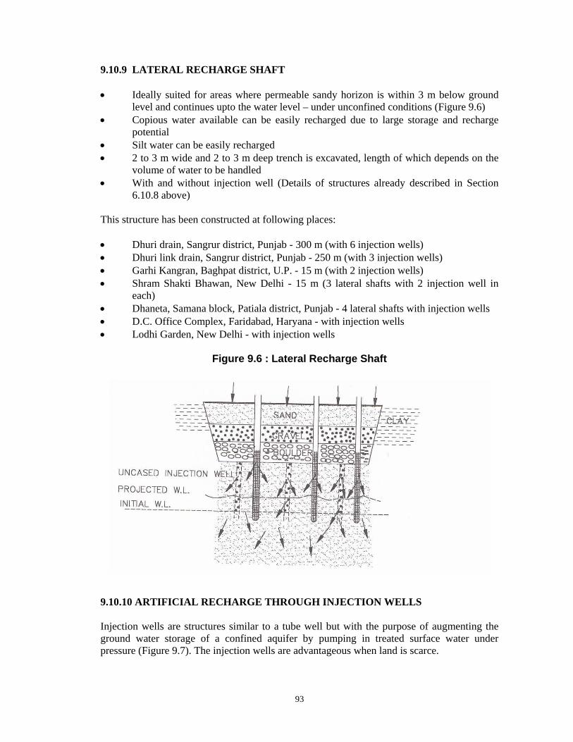
9.10.9 LATERAL RECHARGE SHAFT • Ideally suited for areas where permeable sandy horizon is within 3 m below ground
level and continues upto the water level – under unconfined conditions (Figure 9.6) • Copious water available can be easily recharged due to large storage and recharge
potential • Silt water can be easily recharged • 2 to 3 m wide and 2 to 3 m deep trench is excavated, length of which depends on the
volume of water to be handled • With and without injection well (Details of structures already described in Section
6.10.8 above) This structure has been constructed at following places: • Dhuri drain, Sangrur district, Punjab - 300 m (with 6 injection wells) • Dhuri link drain, Sangrur district, Punjab - 250 m (with 3 injection wells) • Garhi Kangran, Baghpat district, U.P. - 15 m (with 2 injection wells) • Shram Shakti Bhawan, New Delhi - 15 m (3 lateral shafts with 2 injection well in
each) • Dhaneta, Samana block, Patiala district, Punjab - 4 lateral shafts with injection wells • D.C. Office Complex, Faridabad, Haryana - with injection wells • Lodhi Garden, New Delhi - with injection wells
Figure 9.6 : Lateral Recharge Shaft 9.10.10 ARTIFICIAL RECHARGE THROUGH INJECTION WELLS Injection wells are structures similar to a tube well but with the purpose of augmenting the ground water storage of a confined aquifer by pumping in treated surface water under pressure (Figure 9.7). The injection wells are advantageous when land is scarce.
94
Injection Method Water is led directly into the depleted aquifers by providing a conduit access, such as tube well or shaft or connector wells. Recharge by injection is the only method for artificial recharge of confined aquifers or deep-seated aquifers with poorly permeable overburden. The recharge is instantaneous and there are no transit and evaporation losses. Injection method is also very effective in case of highly fractured hard rocks and karstic limestones but very high permeabilities are not suitable, as they do not allow the water to be retained for long periods for use during dry season. However, it is necessary to ensure purity of the source water as well as its compatibility with aquifer to prevent frequent clogging of injection structures, by bacterial growth, chemical precipitation or deposition of silt. Dual-purpose injection wells i.e. injection cum pumping wells are more efficient. Connector injection well where saturated shallow aquifer and over-exploited confined aquifers are tapped in a single well, allows freefall of water from shallow aquifer into the deeper aquifer, thereby reducing cost of injection. Injection method is also used as a “Pressure Barrier Technique” to arrest or reverse saline water ingression. The selection of site for these structures depends upon the configuration of the confined aquifers, hydraulic gradient and location of source of surplus surface water. It is always better to construct it closer to source to save cost of water conveyance. This technique was successfully adopted at temple town of Bhadrachallam in Andhra Pradesh during 1987 to provide safe drinking water to about 2 to 3 lakh pilgrims on the festival of Shriramanawami. The ground water aquifer had meagre reserve and had to be necessarily replenished through induced recharge from Godavari river. The surface water could not be directly pumped to the distribution system due to turbidity and bacteriological contaminations. A water supply scheme was successfully executed by construction of 30 filter point wells of 90 cm diameter which yielded about 60 cum/ha of potable water, mainly the induced recharge from river with phreatic alluvial aquifer acting as filtering medium. Hydraulically, the effectiveness of induction of water in injection well is determined by: • Pumping rate • Permeability of aquifer • Distance from stream • Natural ground water gradient • Type of well In alluvial areas injection well can be provided for recharging a single aquifer or multiple aquifers. An injection pipe with opening against the aquifer to be recharged may be sufficient. However, in case of number of permeable zones separated by impervious rocks, a properly designed injection well with inlet pipe against each aquifer to be recharged need to be constructed. The injection wells as a means of artificial recharge are comparatively costlier and require specialised techniques of tubewell construction. Proper operation and maintenance are necessary to project the recharge well from clogging.

95
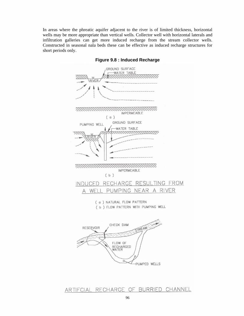
Figure 9.7 : Artificial Recharge through Injection Well 9.10.11 INDUCED RECHARGE It is an indirect method of artificial recharge involving pumping from aquifer, hydraulically connected with surface water, to induce recharge to the ground water reservoir. When the cone of depression intercepts river recharge boundary a hydraulic connection gets established with surface source, which starts providing part of the pumpage yield. In such methods, there is actually no artificial build up of ground water storage but only passage of surface water to the pump through an aquifer. In this sense, it is more a pumpage augmentation rather than artificial recharge measure (Figure 9.8). In hard rock areas the abandoned channels often provide good sites for induced recharge. Check weir in stream channel, at location up stream of the channel bifurcation, can help in high infiltration from surface reservoir to the abandoned channel when heavy pumping is carried out in wells located in the buried channel. The greatest advantage of this method is that under favourable hydrogeological situations the quality of surface water generally improves due to its path through the aquifer material before it is discharged from the pumping well. For obtaining very large water supplies from riverbed, lakebed deposits or waterlogged areas, collector wells are constructed. In India such wells have been installed in Yamuna bed at Delhi and other places in Gujarat, Tamil Nadu and Orissa. The large discharges and lower lift heads make these wells economical even if initial capital cost is higher as compared to tube well.
96
In areas where the phreatic aquifer adjacent to the river is of limited thickness, horizontal wells may be more appropriate than vertical wells. Collector well with horizontal laterals and infiltration galleries can get more induced recharge from the stream collector wells. Constructed in seasonal nala beds these can be effective as induced recharge structures for short periods only.
Figure 9.8 : Induced Recharge

97
Site Characteristics and Design Guidelines A collection well is a large diameter (4 to 8 m) well from which laterals are driven/ drilled near the bottom at one or two levels into permeable strata. The central well is a vertical concrete cassion in pre-cast rings, (wall thickness 0.45 m) sunk upto the bottom of aquifer horizon. The bottom of cassion is sealed by thick concrete plugs. Slotted steel pipes, 9 mm thick, 15 to 50 cm in diameter having open area above 15% and a tapered leading are driven laterally through portholes at appropriate places in the cassion. The successive slotted pipes are welded and driven using special hydraulic jacks installed at the bottom of the cassion. The number of laterals is usually less than 16, thus permitting minimum angle of 22°30”, between two laterals. The maximum length of lateral reported is 132 m and the total length of laterals from 120 to 900 m depending upon requirement of yield. The laterals are developed by flushing and if entrance velocity of water is kept less than 6-9 mm/sec, these do not get filled by sand. The effective radius of a collector well is 75 to 85% of the individual lateral length. 9.10.12 IMPROVED LAND AND WATERSHED MANAGEMENT Improved land and watershed management techniques viz. contour bunding, contour trenching, bench terracing, gully plugging etc. are discussed in Chapter-VII.


![Artificial Recharge-1 [Compatibility Mode]](https://img.dokumen.tips/doc/110x75/577c83f71a28abe054b70306/artificial-recharge-1-compatibility-mode.jpg)