Embed Size (px)
Citation preview

C H A P T E RT H R E E
Introduction toChipsealing Technology

Previous page: Chipsealing underway on the West Coast of the South Island, New Zealand. On the leftis the bitumen sprayer (distributor) applying the binder, the yellow machine in the center is a self-propelledchip spreader being fed chip by the truck on the right. Photo courtesy of Les McKenzie, Opus

3
Chap t e r 3 I n t r o du c t i o n t o Ch i p s e a l i n g Te c hno l og y
3.1 Terminology for Road Surfacings _______________________________________________________________________________________41
3.2 The Road ________________________________________________________________________________________________________________________41
3.3 The Pavement__________________________________________________________________________________________________________________41
3.4 The Chipseal ___________________________________________________________________________________________________________________46
3.4.1 The Binder ________________________________________________________________________________________________________________46
3.4.2 The Aggregate or Sealing Chip_____________________________________________________________________________________48
3.5 Basic Requirements of a Surfacing _____________________________________________________________________________________49
3.6 Sealed Pavement Types _____________________________________________________________________________________________________49
3.7 Chipseal Surfacings __________________________________________________________________________________________________________49
3.7.1 First Coats ________________________________________________________________________________________________________________50
3.7.2 Prime Coats ______________________________________________________________________________________________________________51
3.7.3 Reseals ______________________________________________________________________________________________________________________52
3.7.4 Second Coats ____________________________________________________________________________________________________________52
3.7.5 Pretreatment Seals _____________________________________________________________________________________________________53
3.7.6 Single Coat Chipseal___________________________________________________________________________________________________53
3.7.7 Two Coat Chipseal_____________________________________________________________________________________________________54
3.7.8 Racked-in Chipseal _____________________________________________________________________________________________________56
3.7.9 Voidfill Seal ________________________________________________________________________________________________________________58
3.7.10 Sandwich Seal ____________________________________________________________________________________________________________60
3.7.11 Wet Lock Seal ___________________________________________________________________________________________________________62
3.7.12 Dry Lock Seal ____________________________________________________________________________________________________________63
3.7.13 SAM Seal ___________________________________________________________________________________________________________________65
3.8 Slurry Seal Surfacings _______________________________________________________________________________________________________66
3.8.1 Slurry Seal _________________________________________________________________________________________________________________66
3.8.2 Cape Seal __________________________________________________________________________________________________________________69
3.9 Asphaltic Concrete Surfacings___________________________________________________________________________________________72
3.9.1 OGPA and OGEM______________________________________________________________________________________________________72
3.9.2 Membrane Seal and SAMI ___________________________________________________________________________________________72
3.10 Specialist Surfacings__________________________________________________________________________________________________________73
3.10.1 Fog Coat, Rejuvenating Seal or Enrichment Seal____________________________________________________________73
3.10.2 Geotextile Seal __________________________________________________________________________________________________________74

3
Chap t e r 3 I n t r o du c t i o n t o Ch i p s e a l i n g Te c hno l og y ( c o n t i n u ed )
3.11 Defects in Chipseals_________________________________________________________________________________________________________77
3.11.1 Deformation______________________________________________________________________________________________________________77
3.11.2 Cracking____________________________________________________________________________________________________________________79
3.11.3 Chip Loss __________________________________________________________________________________________________________________82
3.11.4 Potholes ____________________________________________________________________________________________________________________83
3.11.5 Edge Break ________________________________________________________________________________________________________________84
3.11.6 Flushing _____________________________________________________________________________________________________________________84
3.11.7 Bleeding ____________________________________________________________________________________________________________________86
3.11.8 Roughness _________________________________________________________________________________________________________________86
3.11.9 Loss of Texture __________________________________________________________________________________________________________86
3.11.10 Loss of Skid Resistance_______________________________________________________________________________________________87
3.11.11 Conclusion ________________________________________________________________________________________________________________87
3.12 References ______________________________________________________________________________________________________________________88
3
41C h i p s e a l i n g i n N e w Z e a l a n d
Chapter 3 Introduction to Chipsealing Technology
This Chapter aims to introduce the practitioner to the basic principles and terminology
used in chipsealing technology. These basic principles are expanded in Chapters 4, 5
and 6 in sufficient detail so that they can be applied to the design and selection of
chipseals and other surfacing seals. Chapters 7 to 11 describe the practical details of
preparing for and constructing the seals including Chapter 9 which describes the chipseal
design process.
3 . 1 Te rm i no l og y f o r Road S u r f a c i n g sBefore learning the basics of sealing technology, it is important to learn some of the
terms used in roading and some of them are shown in Figures 3-1 and 3-2 relating to
rural and urban roads.
3 . 2 Th e RoadA road1 is a route trafficable by motor vehicles. In law, it is the public right-of-way
between the boundaries of adjoining properties and is owned or administered by a Road
Controlling Authority (RCA). It is often shown as ‘road’ or ‘legal road’ on a plan. In
customary use, road refers to all land between the legal road boundaries and typically
includes the carriageway, footpaths and other accessways, berms and other unpaved
areas constructed for public travel. Where roads have not been formed, the term also
refers to so-called ‘paper roads’.
The carriageway or roadway is that portion of a road or bridge devoted particularly to
the use of vehicles, inclusive of shoulders and auxiliary lanes. A divided road is considered
to have two carriageways.
3 . 3 Th e Pav emen tThe pavement is that portion of the road placed above the design subgrade level for the
support of, and to form a running surface for, vehicular traffic.
Pavement Layers
The subgrade is the trimmed or prepared surface (or upper line) of the formation, i.e.
the surface of the ground, soil, rock or other material. It is the width of the road-bed
after earthworks have been completed, on which the pavement is constructed. It has
been worked and compacted to sustain the traffic load to be imposed on the pavement.
1 Definitions of terms are listed in the Glossary.

3
42 C h i p s e a l i n g i n N e w Z e a l a n d
Figu
re 3
-1
Term
inol
ogy
appl
ied
to a
typ
ical
rur
al r
oad.
Ada
pted
from
TN
Z C
1 A
dden
dum
No.
1:1
997
and
Tran
sit
New
Zea
land
Sta
te H
ighw
ay M
aint
enan
ce C
ontr
act
Prof
orm
a M
anua
l SM
O32
, Iss
ue 2
: Mar
ch 2
002
0.5 m0.5 m
Seale
dCarri
agew
ay
NO
TE
1 Li
mit
of v
eget
atio
n co
ntro
l req
uire
d fo
r sa
fe s
ite d
ista
nces
. Thi
s di
stan
ce m
ust
be a
min
imum
of 3
.0 m
on
stra
ight
s an
d on
the
outs
ide
of c
urve
s, an
d a
min
imum
of 5
.0 m
on
the
insi
de o
f cur
ves
1.0m
0.5
Surface waterChannel
Vegetation Control aroundEdge Marker Post
See NO
TE 1
Exten
t of
control o
n urba
n sta
te hig
hways
Exten
t of
control o
n rural s
tate
highw
ays
Centreline
0.5
Vegetation Control aroundEdge Marker Post
See NO
TE 1
Outer wheel path
All se
aled surfa
ces m
ust b
e ma
intain
edfre
e of
vegetatio
n
Side drain
ELES*
SHP
Unseale
dShou
lder
(no
steep
erthan
12:1
)(M
etalled
or G
rass)
Side
Slope
steep
erthan
12:1
Surfa
ceWater
Chan
nel
minim
um
Side Dr
ain1.5
m avg.
Boundary Fence
I
SHP
Seale
dShou
lder EL
ES*
Inner wheel path
Inner wheel path
Outer wheel path
Pavement
Surfa
cing
Basecourse
Sub-ba
seSubg
rade

3
43C h i p s e a l i n g i n N e w Z e a l a n d
NO
TE
1 Li
mit
of v
eget
atio
n co
ntro
l req
uire
d fo
r sa
fe s
ite d
ista
nces
. Thi
s di
stan
ce m
ust
be a
min
imum
of 2
.0 m
on
stra
ight
s an
don
the
out
side
of c
urve
s, an
d a
min
imum
of 5
.0 m
on
the
insi
de o
f cur
ves
0.5
Vegetation Control aroundEdge Marker Post
Concrete kerb and channel
See NO
TE 1
Exten
t of
control o
n urba
n sta
te hig
hways
Exten
t of
control o
n rural s
tate
highw
ays
Centreline
0.5
Vegetation Control aroundEdge Marker Post
See NO
TE 1
1.5m
avg.
All se
aled surfa
ces m
ust b
e ma
intain
edfre
e of
vegetatio
n
Side drain
2.0m
min
Kerb andchannel
Kerb andchannel
Concrete kerb and channel
Side slo
pe stee
per
than
12:1
0.5 m
Surface waterChannel
0.5 mmi
nimum
Outer wheel path
Inner wheel path
Inner wheel path
Outer wheel path
Pavement
Surfa
cing
BasecourseSub-ba
se Subg
rade
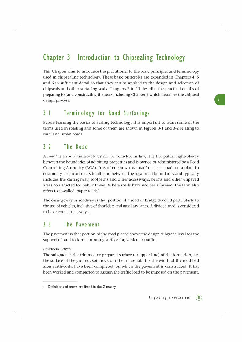
Figu
re 3
-2
Term
inol
ogy
appl
ied
to a
typ
ical
urb
an r
oad.
Ada
pted
from
TN
Z C
1 A
dden
dum
No.
1:1
997
and
Tran
sit
New
Zea
land
Sta
te H
ighw
ay M
aint
enan
ce C
ontr
act
Prof
orm
a M
anua
l SM
O32
, Iss
ue 2
: Mar
ch 2
002
KEY
I =
Inve
rtEL
=
Edg
e Li
neES
=
Edg
e of
Sea
lSH
P =
Sho
ulde
r H
inge
Poi
nt*
= N
ote:
the
Edg
e of
Sea
l may
ext
end
to t
he S
HP
or b
eyon
d

3
44 C h i p s e a l i n g i n N e w Z e a l a n d
The sequence of layers of a pavement, working up from the subgrade, are:
• Sub-base – the material laid on the subgrade below the basecourse, either for thepurpose of making up additional pavement thickness to prevent intrusion of thesubgrade into the base or to provide a working platform. It is the bottom layer of apavement, usually constructed from coarse material.
• Basecourse (base, road base) – one or more layers of material usually constituting theuppermost structural element of a pavement and on which the surfacing may beplaced. It may be composed of fine crushed rock, natural gravel, broken stone,stabilised material, asphalt, or Portland cement concrete.
• Surfacing (also called top surface, wearing course, surface course) – the uppermost partof a pavement, specifically designed to resist wear, including abrasion, stress causedby turning traffic and similar damage from traffic, and to minimise the entry of waterto the pavement. The purpose of the surfacing is to improve the service that a pavementgives to traffic by making it safer, more economical or more pleasant to use.
Surfacings may be constructed of chipseal or asphaltic concrete, or other material.
The materials may be bound, i.e. by a binder; or unbound granular material of
particles consisting of gravel and sand that is compacted but not bound.
Types of PavementFlexible pavements – the thin granular flexible pavement is ideal for use in New Zealandand is typically low cost. In an unbound flexible pavement the basecourse is constructedof unbound granular material. Surfacings for flexible pavements are of the followingtypes: running-course metal (not covered in this book); top surfaces of chipseals; severallayers of chipseals; or thin asphaltic concrete. Thin surface flexible pavements are bydefinition less than 45 mm thick.
Rigid pavements – pavements in high stress situations may be of rigid construction,using high strength rigid concrete as a construction layer, or layers of dense asphalticconcrete. These pavements, while very strong and durable, have relatively high cost.Thick rigid pavements constructed of structural asphalt are generally 110 mm or greaterin thickness.
(Asphaltic concrete layers of 50 to 110 mm thickness are avoided for road pavementsfor structural reasons, and are not considered in this book on chipseals. AustroadsPavement Design Guide (2004) covers the topic.)
Functions of the PavementOne of the most important functions of a pavement is to withstand the loading imposedby traffic and the resulting stresses. The surfacing engineer’s task is to design a pavementthat performs well under those stresses.
• Compressive Stresses (Figure 3-3) – these are the vertical stresses generated by a vehiclethat are dissipated down through the pavement layers.

3
45C h i p s e a l i n g i n N e w Z e a l a n d
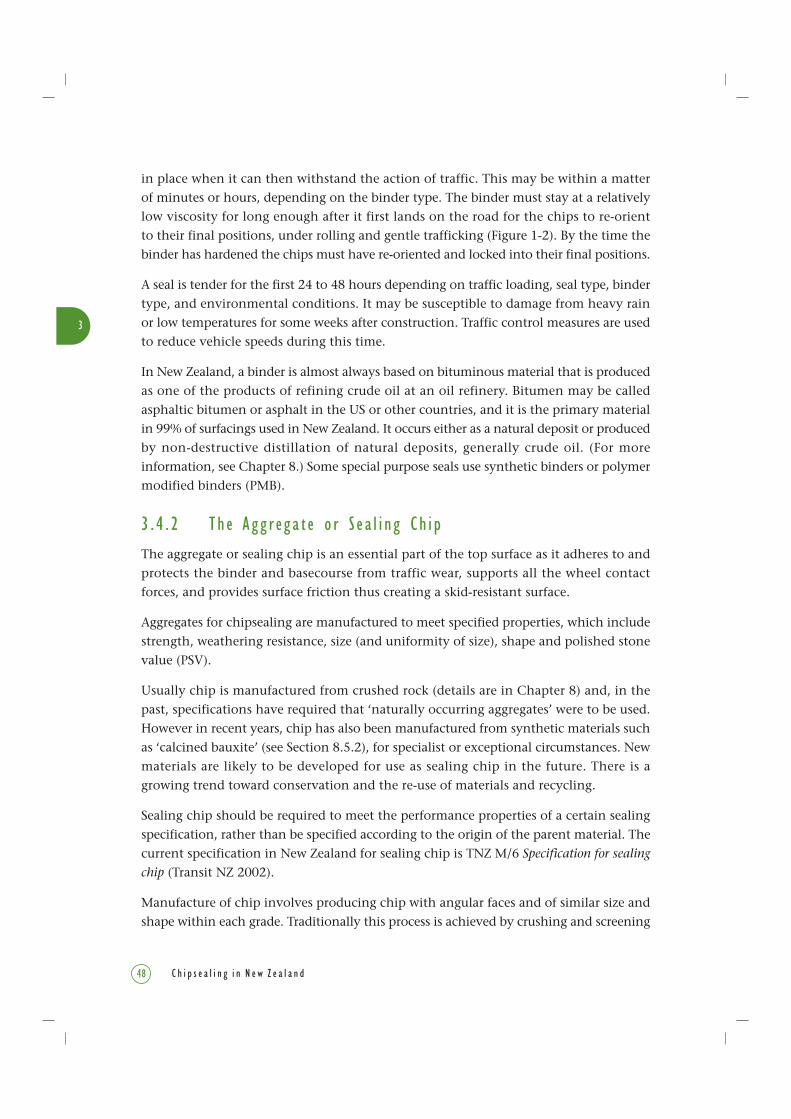
Figure 3-5 Tensile–compressive stresses exerted by a load in a bitumen-bound layer (from Transit NZ 1993).
LOAD W
SUBGRADE
Not Drawn To Scale
Compression Tension
PAVEMENTSTRUCTURE
Figure 3-3 Compressive stress exerted under a wheel load.
PAVEMENTSTRUCTURE
SUBGRADE
LOAD W
P1
P0
P1
Not Drawn To Scale
Figure 3-4 Shear stresses exerted by a braking wheel.
SUBGRADE
LOAD W
PAVEMENTSTRUCTURE
Directionof Travel
Not Drawn To Scale

3
46 C h i p s e a l i n g i n N e w Z e a l a n d
• Shear Stresses (Figure 3-4) – these are generated by shear in the pavement during
braking, acceleration, etc., by the loaded vehicle tyre.
• Tensile Stresses (Figure 3-5) – these are generated by deflection of the pavement
surface by the loaded vehicle tyre. The tensile stresses can only be generated in bound
materials such as cement and bitumen-bound materials, and are not present in
granular basecourse.
The basic philosophy of pavement structural design is to choose, for the different layers,
materials that have sufficient shear strength to carry the traffic loading, and to use those
materials to limit both compressive stress on the subgrade, and tensile strain at the
bottom of any bound layer.
3 . 4 Th e Ch i p s e a lThe surfacing known in New Zealand as a chipseal, or seal, is called a ‘surface dressing’
in the United Kingdom and many other countries, or a ‘sprayed seal’ in Australia. It
comprises a uniformly sized stone, aggregate or ‘sealing chip’ embedded in a 1 to 2 mm-
thick film of bituminous (or synthetic) binder, to provide a thin waterproofing layer as
the top surface of a pavement (Figures 3-6 and 3-7).
Each grade of chip is made up of very nearly single-sized chips of the same shape to
provide a uniform depth of macrotexture.
Macrotexture is the texture of the chipseal that can easily be seen with the eye, i.e.
0.5 mm to 10 mm and is frequently referred to as ‘texture’.
Microtexture is the microscopic surface of the chip, i.e. up to 1 mm.
Single or multiple layers of binder and chip may be used.
3 . 4 . 1 T h e B i n d e r
The binder is a waterproof adhesive viscous material that binds to both the existing road
surface and to the sealing chips of the chipseal to make a cohesive mass.
The binder needs to be liquid enough (i.e. have low viscosity) to be sprayed onto the
pavement surface. To achieve this low viscosity, it may be heated, or diluted with a
volatile solvent such as kerosene when it is called a cutback bitumen, or mixed with
water to make a bituminous emulsion.
It hardens as it cools, or as the solvent evaporates, or the emulsion breaks (i.e. the
emulsion breaks down to its constituents of water, and bitumen which forms a continuous
film on the chips). It then hardens or cures sufficiently to be able to hold the chip firmly

3
47C h i p s e a l i n g i n N e w Z e a l a n d
Figure 3-7 Constructing a chipseal.Clockwise from top left: Spraying binder and spreading chips in one operation. Top right: Spraying the binder.Bottom right: Spreading the chips. Bottom left: Rolling the surface. Photos courtesy of Les McKenzie, Opus
Figure 3-6 Constructing a first coat chipseal near Gisborne in the 1920s was not highly mechanised,compared to the line of construction machines used in the 2000s shown in Figure 3-7.Left: Hand spraying the basecourse, from the tractor-drawn bitumen distributor. Right: Spreading the chipby shovel as the tip truck was not yet in use. Photos courtesy of John Matthews, Technix Group Ltd
3
48 C h i p s e a l i n g i n N e w Z e a l a n d
in place when it can then withstand the action of traffic. This may be within a matter
of minutes or hours, depending on the binder type. The binder must stay at a relatively
low viscosity for long enough after it first lands on the road for the chips to re-orient
to their final positions, under rolling and gentle trafficking (Figure 1-2). By the time the
binder has hardened the chips must have re-oriented and locked into their final positions.
A seal is tender for the first 24 to 48 hours depending on traffic loading, seal type, binder
type, and environmental conditions. It may be susceptible to damage from heavy rain
or low temperatures for some weeks after construction. Traffic control measures are used
to reduce vehicle speeds during this time.
In New Zealand, a binder is almost always based on bituminous material that is produced
as one of the products of refining crude oil at an oil refinery. Bitumen may be called
asphaltic bitumen or asphalt in the US or other countries, and it is the primary material
in 99% of surfacings used in New Zealand. It occurs either as a natural deposit or produced
by non-destructive distillation of natural deposits, generally crude oil. (For more
information, see Chapter 8.) Some special purpose seals use synthetic binders or polymer
modified binders (PMB).
3 . 4 . 2 Th e Agg r eg a t e o r S e a l i n g Ch i p
The aggregate or sealing chip is an essential part of the top surface as it adheres to and
protects the binder and basecourse from traffic wear, supports all the wheel contact
forces, and provides surface friction thus creating a skid-resistant surface.
Aggregates for chipsealing are manufactured to meet specified properties, which include
strength, weathering resistance, size (and uniformity of size), shape and polished stone
value (PSV).
Usually chip is manufactured from crushed rock (details are in Chapter 8) and, in the
past, specifications have required that ‘naturally occurring aggregates’ were to be used.
However in recent years, chip has also been manufactured from synthetic materials such
as ‘calcined bauxite’ (see Section 8.5.2), for specialist or exceptional circumstances. New
materials are likely to be developed for use as sealing chip in the future. There is a
growing trend toward conservation and the re-use of materials and recycling.
Sealing chip should be required to meet the performance properties of a certain sealing
specification, rather than be specified according to the origin of the parent material. The
current specification in New Zealand for sealing chip is TNZ M/6 Specification for sealing
chip (Transit NZ 2002).
Manufacture of chip involves producing chip with angular faces and of similar size and
shape within each grade. Traditionally this process is achieved by crushing and screening

3
49C h i p s e a l i n g i n N e w Z e a l a n d
into sizes or grades as required by the TNZ M/6 specification (more details in Section 8.5).
Different sizes or grades of chip are used. The size and type of chip is decided during a
detailed treatment selection and design process for a chipseal (Chapter 6). Grade sizes of
sealing chips are Grades 2 (coarsest), 3, 4, 5, and 6 (finest). For chipseals constructed of two
or more layers of different sized chips, a two figure convention is used. The first chip listed
is the lower layer in the chipseal, therefore Grade 3/5 means that Grade 3 is used in the
first layer or coat, and finer Grade 5 chip is used in the overlying second layer or coat.
3 . 5 Ba s i c R equ i r emen t s o f a S u r f a c i n gThe purpose of a top surface is to:
• protect the pavement and subgrade from environmental damage related to weathering;
• waterproof the pavement;
• provide a wearing surface that is resistant to abrasion by vehicles using it, and resistant
to crushing under traffic loading;
• provide a dust-free surface under any conditions, and thereby contribute to traffic
safety, comfort, and convenience by providing a smooth surface;
• provide non-skid properties to an existing surface;
• provide pleasant travel at an economical cost.
3 . 6 S e a l e d Pav emen t Typ e sPavements in New Zealand fall into one of two main classes:
• Unsealed (not discussed further in this book);
• Sealed.
Sealed pavements can be divided into a further four broad classes of surfacing:
• Chipseal surfacings (Section 3.7)
• Slurry Seal surfacings (Section 3.8)
• Asphaltic Concrete surfacings (Section 3.9)
• Specialist surfacings (Section 3.10).
3 . 7 Ch i p s e a l S u r f a c i n g sMany chipseal types exist. Some can be used for more than one purpose while others
are very specialised in their use or require a specific set of circumstances in order to be
successful.

3
50 C h i p s e a l i n g i n N e w Z e a l a n d
Chipseal surfacings are considered as either:
• First coats (includes Prime coats);
• Reseals (includes Second coats and Pretreatment Seals).
3 . 7 . 1 F i r s t C o a t s
A first coat is the initial seal on a prepared unsealed surface, which is usually a basecourse.
They must be designed to adhere to and provide waterproofing for the unsealed prepared
basecourse. They are the first treatment for a granular pavement or overlay, and serve
principally to prepare the base for the main treatment.
A first coat seal (Figures 3-8 and 3-9) should be an integral part of the pavement construction
design and the planned subsequent seals in years to come. Selection of a first coat treatment
and of future seal coats must therefore be included during the initial pavement construction
design. Generally, a first coat is only expected to last one year before being resealed,
although they may last much longer on low traffic volume roads.
Figure 3-9 A first coat seal under construction on a road on the West Coast of the South Island.Photo courtesy of Les McKenzie, Opus
Figure 3-8 A first coat seal. Courtesy of Austroads Sprayed Sealing Guide (2004)
Uniformly sized chipSealing binder
BasecourseBinder penetration into base

3
51C h i p s e a l i n g i n N e w Z e a l a n d
First coat binders need to be fluid enough to wet through dust and adhere to the stone
surfaces, yet not so fluid that they will neither hold the sealing chip nor run off into
side drains. Past practice has been to include relatively large quantities (>6 parts per
hundred (pph)) of cutter2 in first coat binders to aid the wetting process.
Although very few occasions occur where the first coat seal itself does not perform its
function, the success of the first coat seal is a direct reflection of the quality of pavement
or basecourse construction at the time of sealing.
Construction of a surface to which a first coat will adhere must be a well-bound, relatively
dry, smooth hard surface, with a surface of clean stones showing and with no unbound
fine material (dust), see Chapter 7 for more details.
A first coat may be applied to an existing pavement as part of a repair patch or applied
to the pavement shoulders as a seal widening.
3 . 7 . 2 P r ime Coa t s
High cutback-content prime coats (also called prime seals) which have up to 50% cutter
in the bitumen have been used and are often specified in other countries. In New Zealand
however, the use of high cutback prime coats is not encouraged because of the hazardous
nature of the cutback binder (known as the primer) and its effects on the environment.
If a prime coat is used, its main function is to ensure a good bond between the larger
stones in the basecourse and the surfacing. To achieve this, a low viscosity, bitumen-
based binder (the primer) is used, which penetrates or ‘wets through’ any surface dust
layer then adheres firmly to the stone beneath (Figure 3-10).
2 Cutback bitumen is a bitumen which has its viscosity temporarily reduced by the addition of a volatilediluent or ‘cutter’, such as kerosene, to make it more fluid for ease of application.
To achieve this function of providing a good bond between basecourse and surfacing,
the primer must have the following properties:
• It must be able to penetrate the fine surface dust layer that always coats the aggregate
particles of a granular basecourse surface.
Primer showingpenetration into base
Basecourse
Figure 3-10 A prime coat seal. Courtesy of Austroads Sprayed Sealing Guide (2004)
3
52 C h i p s e a l i n g i n N e w Z e a l a n d
• It must adhere easily and quickly to the surface of the coarser particles in the basecourse
surface.
• It must be compatible with the subsequent surfacing to promote rapid adhesion to it.
These demands can be met by using a penetration grade bitumen binder which is cut
back to a low viscosity with a rapid to medium curing volatile cutter, and contains an
adhesion agent. Kerosene is the usual cutter although other solvents such as mineral
turpentine can be used.
Because cutback prime binders are hazardous, alternatives to prime coats are available.
These can include emulsified primes, and the mixing of slow-breaking emulsions into
the basecourse layer during the construction process of watering and compacting the
basecourse.
These techniques can allow the use of harder, more viscous chipsealing binders in the
next seal coat to be applied. These can provide improved waterproofing, longer seal life,
and allow the use of larger sized chip.
Prime seals can also be used on timber bridge decks to promote adhesion between the
chipseal and the timber.
3 . 7 . 3 R e s e a l s
A reseal is any chipseal applied to a surface which has previously been sealed. A reseal
is applied because the existing surfacing is showing, or is about to show, signs of distress.
Reasons for resealing a surface is to improve one or more of the following:
• Loss of waterproofing;
• Reduced skid resistance;
• Ageing and brittleness of binder;
• Chip loss;
• Old chipseal showing hairline cracks requiring repair;
• To reinstate or increase surface texture (macrotexture).
3 . 7 . 4 S e c ond Coa t s
The term second coat refers to the reseal applied to a first coat seal. In the past, the term
was used to differentiate between the reseal applied after a first coat and subsequent
reseals. They were almost without exception applied within 12 months of the first coat
being laid on state highways but other RCAs had different policies. Such policies had
usually been made because the RCAs were confident of obtaining adequate waterproofing
and long life of the seal using a delayed second coat.

3
53C h i p s e a l i n g i n N e w Z e a l a n d
However today, for all intents and purposes, a second coat is a reseal and will be referred
to as a reseal from here on.
In more recent years pavement and surfacing designers have been resealing first coats
on a ‘need to’ basis rather than following a blanket policy. If the timing of a reseal is
based on engineering judgement, the reseal to a first coat can extend the overall life of
the pavement surfacings, because it is then sealed at the most appropriate time which
maximises the value gained. Some first coats may not need to be resealed for several
years, depending on factors such as the quality of pavement construction, the first coat
seal type, and traffic volume. However care needs to be taken because extending the life
of a first coat beyond its appropriate life may result in premature pavement failures.
3 . 7 . 5 P r e t r e a tmen t S e a l s
Treatments which may be applied to a surface as a pretreatment to resealing are many, and
some are included in the category of seals. They are discussed in detail in Section 7.1.3.
3 . 7 . 6 S i n g l e C o a t Ch i p s e a l
A single coat is a single sprayed application of sealing binder followed immediately with
a single application of chip which is spread and rolled into place (Figure 3-11). It is
always applied using a larger chip than the existing surface chip, with the exception
being a voidfill (Section 3.7.9).
Category
• First coats.
• Reseals.
When to use
• Best in situations where traffic stresses are not great.
• Suitable for low to high traffic volumes.
Existing surface condition required
• When applied as a reseal, existing macrotexture variation must be within limits
relative to the chip size nominated in the reseal.
Figure 3-11 A single coat chipseal.
Uniformly sized chipBinder
Basecourse
Old chipseal

3
54 C h i p s e a l i n g i n N e w Z e a l a n d
• Existing surface texture must be consistent, not too coarse, with a sound surface andsound pavement condition to be successful.
Advantages
• Low cost.
• Can provide excellent waterproofing because the binder is concentrated in one layer.
• Will provide macrotexture.
• Simple to construct.
• Can perform well in most situations provided they are well constructed, includingstressed sites such as steep grades provided the traffic volumes are of medium to lowdensity.
Limitations
• Limited resistance to traffic stresses (e.g. cornering stresses).
• Should never be applied with a chip that is the same size as existing surface chip,unless it is an old worn surface.
• Not very tolerant of a wide variation in underlying texture.
Summary comments
• A straightforward standard seal.
• Single coat seals have been used extensively throughout New Zealand for as long aschipseal surfacings have been constructed.
• Their simplicity and ease of construction make them a cost-effective choice in allsimple non-stressed environments.
3 . 7 . 7 Two Coa t Ch i p s e a lA two coat is a chipseal with two applications of binder and two applications of chip(Figure 3-12), applied in the following sequence:
• An application of sprayed binder is followed immediately with an application oflarge size chip.
• Then a second application of sprayed binder, and a second application of smaller chip.
• Both coats are applied one after the other with little or no time delay between coats.
Figure 3-12 Two coat seal (two applications of chip and two applications of binder), shown here as a‘Two Coat as a First Coat seal’.
Second (smaller) chipFirst (larger) chip
BasecourseFirst application of binder
{Second application of binder,bitumen-coated larger chipsare visible from above

3
55C h i p s e a l i n g i n N e w Z e a l a n d
Two coat chipseals and other chipseals with more than one layer of chip are sometimes
known as ‘multicoat seals’.
Category
• First coats.
• Reseals.
When to use
• In areas with low or high traffic volumes.
• In difficult conditions, often where other seal types are not suitable because of site
conditions, e.g. high stress areas.
• Can be used as a first coat, in which case they are called ‘two coat as a first coat’ seals.
• Often used when a non-conventional binder is specified, e.g. emulsions or PMBs, to
aid chip retention.
• A two coat seal can be used without a pretreatment seal to seal off a porous underlying
surface.
• Reasonably resistant to snow-plough damage as has less macrotexture than a single
coat seal.
Existing surface condition required
• When applied as a reseal, macrotexture variation must be within limits relative to
the chip size nominated in the reseal.
• Consistent underlying texture, although it is more tolerant of texture variation than
a single coat.
Advantages
• Able to withstand more traffic stress than most other chipseal surfacings.
• More tolerant of texture variations in existing conditions than other chipseal surfacings.
• Can be constructed as a stress-resistant seal coat.
• Generally durable and long lasting due to chip interlock between the two layers.
Limitations
• More costly than single coat chipseals.
• During the construction of two coat seals and through their early life, loose chip can
create considerable nuisance.
• Loose chip can be evident for many months after construction and regular sweeping
is required.
• The appearance and performance of a two coat seal is subject to the construction
techniques employed.

3
56 C h i p s e a l i n g i n N e w Z e a l a n d
• Chip size compatibility and spread rates are critical, and directly affect the final
outcome.
• Bitumen can be picked up by vehicle tyres (called ‘tracking’) because binder has been
sprayed on the large chip.
• Depending on construction techniques, the seal can be rough and noisy, or smooth
and quiet under the action of vehicle tyres.
Summary comments
• Two coat chipseals have been used in recent years as a cure to all problems and have
been applied in many situations, but they are not a replacement for all seals.
• Their performance and appearance however is very dependent on construction and
the selection of chip size and compatibility. (They can be rough and noisy or smooth
and quiet, depending on the construction techniques that are used.)
• Construction techniques vary in rates of chip application and rolling, e.g. if the first
coat is rolled (especially with a steel roller), a very different seal is constructed (because
more chip realignment occurs) compared to one which is not rolled or not trafficked
between coats.
• Although more complicated than a standard single coat chipseal, two coat seals have
been used for some years now, and a skilled and experienced crew should have little
trouble with construction of a two coat chipseal.
3 . 7 . 8 Ra c ked - i n Ch i p s e a l
A racked-in chipseal consists of one application of binder and two applications of chip
(Figure 3-13), applied in the following sequence:
• A single application of binder is applied, followed by the application of a large chip
which is widely spaced (with ‘windows’ between the chips).
• This is followed by a further application of smaller chip.
• The smaller chips fall into the windows between the large chips of the first application,
and adhere to the layer of binder below.
Figure 3-13 A racked-in seal (one application of binder, two of chip).
Second (smaller) chip
First (larger) chip
BasecourseSingle application of binder

3
57C h i p s e a l i n g i n N e w Z e a l a n d
Category
• First coats.
• Reseals.
When to use
• In areas with low or high traffic volumes.
• In difficult conditions where other seal types are not suitable, and where loose chip
from two coats cannot be tolerated.
• On just the high-stress intersections in a long run of single coat chipseal.
• In town centres where loose chip needs to be kept to a minimum.
• Often used where a non-conventional binder is specified, e.g. a PMB, to aid chip
retention.
• Reasonably resistant to snow-plough damage as has less macrotexture than a single
coat seal.
Existing surface condition required
• When applied as a reseal, macrotexture variation must be within limits relative to
the chip size nominated in the reseal.
• Consistent surface texture and pavement condition are required to provide a good
surface.
• Surface conditions required are similar to those for single coat seals.
• The most important objective during racked-in seal construction is to produce a first
layer that ensures a surface condition with adequate windows left between the chips
of the first layer when they are being spread onto the binder. This allows the smaller
chip to fit between them.
Advantages
• Cost effective.
• Able to withstand more traffic stress than single coat chipseals.
• Can withstand more texture variation in existing conditions than a single coat seal.
• Less loose chip than single coat seals.
• Can be constructed quickly.
• Can use less binder than a two coat or single coat seal.
• Racked-in seals generally do not generate tracking of bitumen.
Limitations
• As with two coat seals, the construction techniques used will significantly influence
the final outcome.

3
58 C h i p s e a l i n g i n N e w Z e a l a n d
Summary comments
• Racked-in seals were first constructed many years ago, and in more recent times have
come back into use.
• Racked-in seals are being used in moderately stressed situations where two coat seals
which generate loose chips are less favoured.
• Although more complicated than a standard single coat chipseal, they have been in
use for some years, so a well-trained crew should have little trouble with seal
construction of a racked-in seal.
3 . 7 . 9 Vo i d f i l l S e a l
A voidfill seal is a single very light application of binder, followed by a single application
of small chip designed to fit into the macrotexture of an existing chipseal surface
(Figure 3-14). Also known as a void seal.
Category
• Reseal.
When to use
• On a surface requiring resealing that has coarse texture which creates excessive binder
demand (usually when sand circles, used to determine macrotexture of the surface,
are 170 mm or less).
• On a surface showing early signs of chip loss. However, if the chip loss is advanced a
voidfill will not fix the problem and a texturising seal should be used (Section 7.3.4.3).
Existing surface condition required
• Coarse texture.
• Not to be applied to a smoother textured surface.
Advantages
• Provides a cost-effective, smooth, consistent surface for subsequent reseals.
• Uses minimal binder.
• The chip application rate is lower than that for a single coat seal.
• When used appropriately, they can prevent cumulative development of uneven
texture.
Figure 3-14 A voidfill seal (a single application of binder and small chip over existing seal).
Smaller chipsealSingle application of binderOld, larger sized chipseal
Basecourse

3
59C h i p s e a l i n g i n N e w Z e a l a n d
• They can prevent long-term problems caused by excess binder in the chipseal layersbecause proportionally more chip is present and less bitumen is required.
Limitations
• Can only be applied to coarse textured surfaces.
• As they reduce texture, the resulting smooth surfaces can influence skid resistanceat high speeds in wet weather. Therefore a new voidfill should not have less than0.9 mm macrotexture depth.
• Generally they need to be resealed in 2 to 3 years, except in areas with low trafficvolumes where they can achieve a very long life.
• Incorrect chip size selection (e.g. too large) can re-create coarse texture and so defeatthe purpose of the voidfill seal.
• They should not be applied where excess binder has already accumulated at the roadsurface (called flushing), because the binder will be displaced and rise up around thevoidfill making the problem worse.
Summary comments
• A voidfill seal fills the existing coarse texture with chip and requires very little binder.
• The resulting seal is a smooth even-textured surface on which subsequent reseals canbe applied, using minimal binder application rates.
• Normally a new voidfill should not have less than 0.9 mm texture depth.
• While they can last a long time in areas of low traffic volumes, generally they havea short life.
• A relatively simple seal type and comparatively easy to obtain a good job.
• Voidfills play a very important role in the life cycle of the pavement surfacing becausethe voids are filled with chip rather than binder. This alters the overall ratio of binderto chip (called the binder:stone ratio).
• Because more chip is present and less bitumen is required, the binder:stone ratio islowered in the successive seal layers, and this reduces the chance of layer instabilitydeveloping (more detail is in Section 4.7.4.2).
• Care is required to select the correct chip size because the aim is to fill the void asclose to level with the existing chip as possible, and to avoid using a large chip thatcan sit higher than the existing chip.
• Design of voidfill bitumen application rates is by experience. Usually an experiencedseal designer selects a relatively low binder application rate, rather than apply thedesign algorithm which would result in application rates that are too high.
• Voidfill seals must not be applied to flushed or bleeding wheelpaths (i.e. bitumenat the surface) as they will tend to make these problems worse. Other treatments for
such distressed areas can be sandwich seals, water cutting, etc. (see Chapter 7 for
treatments for flushed and bleeding wheelpaths.)

3
60 C h i p s e a l i n g i n N e w Z e a l a n d
3 . 7 . 1 0 S andw i c h S e a l
A sandwich seal (Figure 3-15) is applied in the following sequence:
• A layer of large chip is spread directly on the existing surface.
• This is followed by a relatively light application of binder.
• A smaller chip is then spread directly onto the sprayed binder.
• The surface is rolled to compact the seal.
Category
• Reseal.
When to use
• On existing sealed surfaces which are unsuitable for conventional resealing as theyare rich in binder (e.g. flushed surfaces with little to no texture).
• To help correct binder:stone ratios in unstable or potentially unstable seal layers.
Existing surface condition required
• Little to no texture, and rich in binder.
Advantages
• Sandwich seals can be a cost-effective seal to restore texture to smooth binder-richsurfaces.
• They can prolong the life of a pavement surface which is nearing the unstable phase,usually related to successive build-up of seal layers.
Limitations
• Because the surface to which a sandwich seal is applied is generally nearing theunstable phase, their performance can be unpredictable.
• If the existing surface is very rich in binder, the sandwich seal may only temporarilyrestore texture.
• Their success is dependent on the accurate assessment of the amount of free binder inthe existing surface, which is used in calculating the appropriate binder application rate.
• Success and appearance are also subject to chip size compatibility and constructiontechniques.
Figure 3-15 A sandwich seal.
Old, flushed chipseal
Basecourse
First layer of larger chip(no binder under it)
Second (smaller) layer of chip
Single binder application
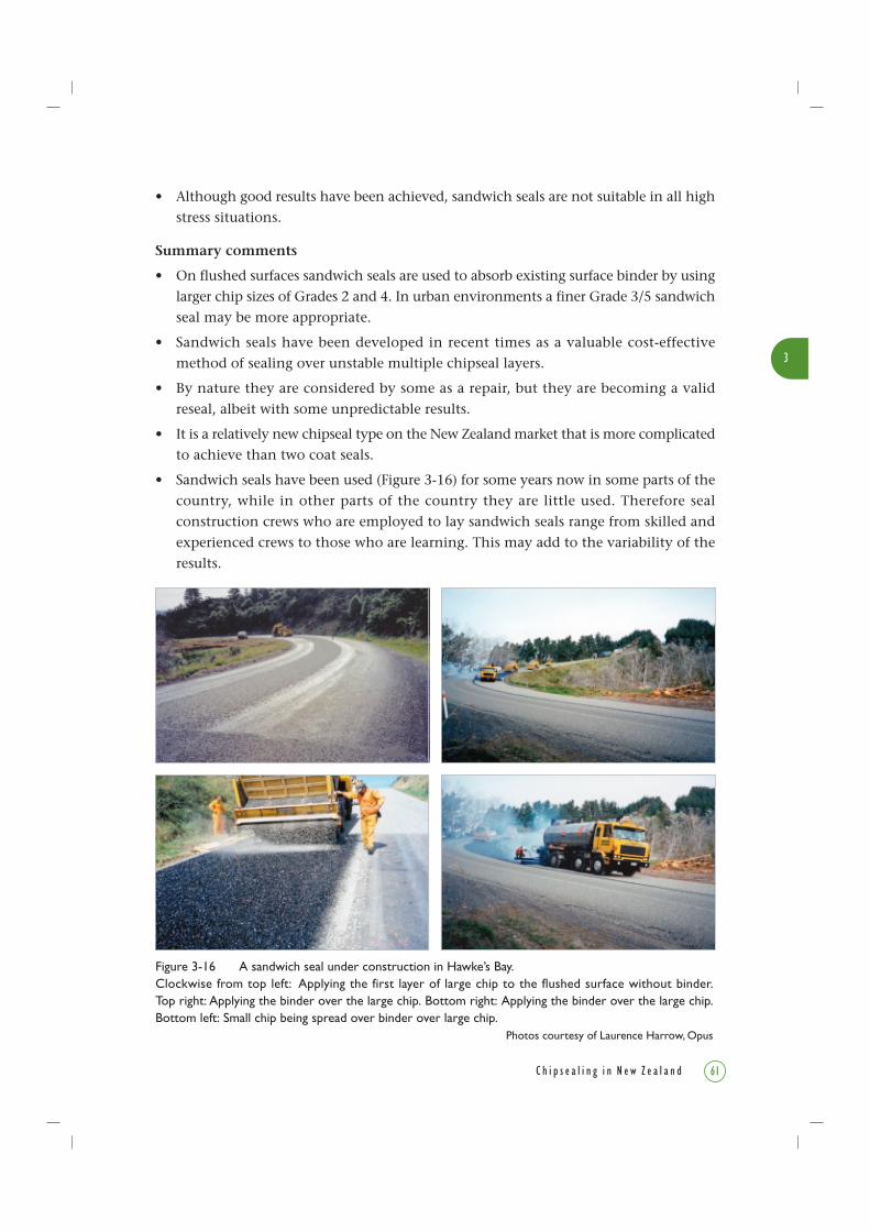
Figure 3-16 A sandwich seal under construction in Hawke’s Bay.Clockwise from top left: Applying the first layer of large chip to the flushed surface without binder.Top right: Applying the binder over the large chip. Bottom right: Applying the binder over the large chip.Bottom left: Small chip being spread over binder over large chip.
Photos courtesy of Laurence Harrow, Opus
3
61C h i p s e a l i n g i n N e w Z e a l a n d
• Although good results have been achieved, sandwich seals are not suitable in all high
stress situations.
Summary comments
• On flushed surfaces sandwich seals are used to absorb existing surface binder by using
larger chip sizes of Grades 2 and 4. In urban environments a finer Grade 3/5 sandwich
seal may be more appropriate.
• Sandwich seals have been developed in recent times as a valuable cost-effective
method of sealing over unstable multiple chipseal layers.
• By nature they are considered by some as a repair, but they are becoming a valid
reseal, albeit with some unpredictable results.
• It is a relatively new chipseal type on the New Zealand market that is more complicated
to achieve than two coat seals.
• Sandwich seals have been used (Figure 3-16) for some years now in some parts of the
country, while in other parts of the country they are little used. Therefore seal
construction crews who are employed to lay sandwich seals range from skilled and
experienced crews to those who are learning. This may add to the variability of the
results.

3
62 C h i p s e a l i n g i n N e w Z e a l a n d
3 . 7 . 1 1 We t L o c k S e a l
A wet lock maybe applied to a new seal to improve its durability under unexpected
traffic stress. Wet locks create an interlocking seal layer using smaller chip which fits
into the texture between the large chips. A light application of binder is used to make
sure the smaller chip adheres to the underlying seal (Figure 3-17).
They differ from two coat seals in that they are not necessarily constructed immediately
one coat after the other, and the two coats can use different binders. Often the wet lock
seal is applied after a period of time (e.g. the next day). A wet lock is not used as a first
coat seal but could be applied to a first coat seal. The first coat is designed as a single
coat seal and the second coat as a voidfill.
The binder:stone ratio in a wet lock is higher than that for a racked-in seal or two coat
seal. This means a wet lock may increase the risk of future flushing.
A bitumen emulsion is often used as a binder as the emulsion binder application rate
is typically low, reducing the risk of binder run-off.
Category
• Reseal.
When to use
• To enhance surfacing strength.
• Where a single coat is failing or about to fail (usually due to under-application of
binder). Applying a wet lock avoids a seal failure.
• Can be used on just the high stressed intersections in a long run of single coat chipseal.
Existing surface condition required
• Coarse texture, to enable the small chip to fit between the large chip.
• The selection of chip size is important for the seal to be successful.
Advantages
• Wet locks can greatly enhance the strength of a seal without generating as much
loose chip as does a two coat seal, because chips on the bottom layer are rolled and
swept before the wet lock coat is applied.
Figure 3-17 A wet lock seal.
Second (smaller) chipSecond application of binderFirst (larger) chip
First application of binder
Basecourse

3
63C h i p s e a l i n g i n N e w Z e a l a n d
• When designed and constructed appropriately, they can produce less traffic noise, have
more consistent texture, and are more resistant to traffic stress than a two coat seal.
Limitations
• When used as a repair, care is required with binder application rates to avoid over-
application which results in flushing.
• Overall macrotexture will be reduced but should still meet minimum texture requirements.
• When designed and constructed with a delay between the applications of the two
layers, the risk of traffic damage and chip loss to the bottom layer is very high.
Summary comments
• Wet locks are not used often and are usually employed as a repair of a single coat
which shows early signs of failure.
• Very strong, well-constructed seals can be achieved but the risk of flushing that may
be caused by excess binder needs to be assessed in the design.
• When designed specifically and not used as a repair a strong seal can be achieved,
but the risk of traffic damage to the bottom layer may be high if the delay between
coats is too long.
• Wet locks are no more complicated to apply than a standard single coat chipseal or
voidfill, and a chipsealing crew should have little trouble with its construction.
• Can be designed and used for the construction of a strong well-bound seal coat on
a new pavement construction where the bottom chipseal layer is not trafficked before
the wet lock is applied.
3 . 7 . 12 D r y L o c k S e a l
A dry lock is the application of small chip to a new chipseal (Figure 3-18), usually after
some traffic has used the new seal. No binder is applied before spreading the dry lock
chip. The small chip fits into the texture of the new larger seal chip (and is chosen so
it only just makes contact with the binder) where it forms shoulder-to-shoulder contact
to add strength and prevent damage to the new seal.
It is used to provide a temporary running coat to protect a new seal from traffic stresses
because it provides a protective layer of chip over the new seal.
Figure 3-18 A dry lock seal.
Second (smaller) chip
First (larger) chip
BasecourseSingle application of binder

3
64 C h i p s e a l i n g i n N e w Z e a l a n d
Category
• A dry lock is not a reseal but can be applied to a reseal.
• A dry lock is not a first coat but can be applied to a first coat.
When to use
• In any circumstance where some added protection from damage caused by traffic
stresses is required.
• Can be used on just the high stressed intersections in a long run of single coat chipseal.
• Usually applied to a larger size single coat chipseal where the small chip of a dry lock
will help prevent the large chip from being plucked out of place.
Existing surface condition required
• Fresh seals, usually a few hours after sealing and rolling is complete.
• Coarse-textured seals with large size chips to enable the locking chip to fit into the
texture.
Advantages
• Inexpensive and easily applied.
• Can resist moderate traffic stresses without the need for a two coat or a racked-in seal.
Limitations
• Applying the locking chip too early, i.e. before the large chip has been rolled and is
embedded, can cause the small chip to settle beneath the large chip and prise it loose.
• A dry lock seal will reduce overall macrotexture.
Summary comments
• Dry locks are often referred to as inexpensive insurance against traffic damage for
single coat seals in moderately stressed situations.
• A dry lock seal is very simple to achieve, and no binder is required.
• A dry lock seal is quite different to a racked-in seal. The small chip fits tightly between
the large chip which has been rolled and bedded in. Individual single small chips
fit between large chips and only just make contact with the binder.
In a racked-in seal, more than one small chip will fit between the large chips and the
small chip makes contact and embeds into the binder. The large chip will not
necessarily be rolled and fully embedded before application of the small chip. This
achieves a seal that is very different in both appearance and performance.

3
65C h i p s e a l i n g i n N e w Z e a l a n d
3 . 7 . 1 3 S AM S e a l
A SAM is a Stress Absorbing Membrane. SAM seals can be single coat, two coat or racked-
in seals which use a PMB (Figure 3-19).
The use of a PMB introduces properties to the seal coat which make it more resistant
to reflective cracking from an underlying cracked surface. (PMBs are discussed in detail
in Section 8.4.)
Category
• Reseal.
When to use
• To seal cracked pavements.
Existing surface condition required
• Pavement defects, e.g. cracking, that can be improved by the special properties of PMB.
• The same conditions as required for single coat, two coat or racked-in seals.
Advantages
• SAM seals can provide enhanced performance in cracked pavement situations (see
Section 8.4.7 for uses of PMBs).
• A SAM seal will not repair a flushed surface but can prevent binder pick-up on vehicle
tyres (tracking) in hot weather.
Limitations
• SAM seals are more costly than conventional binder seals.
• Construction techniques must carefully comply with best practice and the binder
manufacturer’s recommended procedures.
• Limitations are similar to those of PMBs (Section 8.4.10).
Summary comments
• Although SAM seals are in fact PMB seals, SAMs are specifically designed to minimise
reflective cracking in a pavement, whereas a PMB seal can be used for a variety of
other purposes.
Figure 3-19 A SAM seal. Courtesy of Austroads Sprayed Sealing Guide (2004)
Seal chipStress absorbing binder (PMB)
Weak or cracked substrateCracks

3
66 C h i p s e a l i n g i n N e w Z e a l a n d
• They are essentially a single coat, a two coat, or a racked-in seal with a binder that
is specifically modified for a particular situation.
• As a PMB is involved, a relatively high pavement temperature (e.g. 20°C) is required
at the time of chipsealing.
• The same comments for conventional single coats, two-coats and racked-in seals
apply also to their PMB equivalents.
• For resisting or delaying reflective cracking, high binder application rates (>2 /m2)
are used.
3 . 8 S l u r r y S e a l S u r f a c i n g sAs a slurry seal has properties of both chipseal and asphalt, it is included in this book.
An in-service slurry behaves and fails like a chipseal but the technology to produce it
is more like that used for an asphalt.
Slurry seals are specifically designed mixes of aggregates, an emulsified binder and
additives, applied to a surface and spread to a specific depth.
Depths of slurry seals vary, depending on the aggregate sizes used, and typically they
range from 5 mm to 8 mm in depth.
Where the emulsion binder is modified by adding polymer (usually up to 3% of the
binder), the technically correct term for a slurry seal is microsurfacing. The term
microsurfacing is well recognised overseas but has not found favour in New Zealand.
Most slurry sealing in New Zealand contains polymer modified emulsion (PME) and
thus meets the specified criteria for microsurfacing.
3 . 8 . 1 S l u r r y S e a l
A slurry seal (Figure 3-20) is a surfacing comprising a specially graded aggregate (ISSA
2004a, b, Austroads 2003) mixed with an emulsion binder, a small percentage of filler
(commonly cement), and water.
Figure 3-20 A slurry seal. Courtesy of Austroads Sprayed Sealing Guide (2004)
Slurry sealExisting surface (seal)
Basecourse

3
67C h i p s e a l i n g i n N e w Z e a l a n d
These components are mixed in the correct proportions, usually in a truck-mountedmixing plant (slurry truck), and the resulting slurry is spread onto the road surface bya special spreader box dragged behind the truck.
The four recognised aggregate gradings that are available for slurry seals range fromType 1 (nominal 3 mm maximum size) through to Type 4 (nominal 10 mm maximum size).
Type 1 is used where a very fine texture is required. Nominal aggregate size is 3 mmresulting in a surface texture of typically 0.3 mm. It is seldom used in New Zealand andis most suited for use on footpaths or voidfilling on airport runways.
Type 2 is most commonly used as a reseal, wearing course and/or voidfill on urbanresidential streets, low to medium volume roads, carparks and footpaths where finetexture, low traffic noise and lack of loose chips are desirable. It has a nominal maximumparticle size of 5 mm, resulting in a surface texture of around 0.5 mm.
Type 3 offers a coarser texture for use on roads with higher traffic volumes (e.g. on statehighways). It has a nominal maximum particle size of 7 mm.
Type 4 has the coarsest texture and can be successfully applied as a wearing course onhigh traffic volume sites. It is however most suited for rut filling and minor shapecorrection of the surface as a stand-alone repair or pre-reseal treatment.
Category
• Reseal (technically deemed to be a thin asphaltic surfacing).
When to use
• As a cost-effective alternative to chipseals where an asphalt-like surface is desirable.
• As a thin wearing course to restore skid resistance and to prevent chip loss (also calledfretting).
• To reduce road noise.
• Slurry seal has been reported to have been used over ageing porous asphalts or similarsurfaces that are beginning to fret and wear away. The slurry effectively fills the wornareas, prevents further wear and restores a smooth even surface that can extend theseal life by many years.
• Can be used to repair ruts in the pavement by applying a layer of slurry just in therut itself.
Existing surface condition required
• The surface should be clean as mud and oil deposits will be detrimental to a goodbond.
• Thick build-ups of pavement markings, e.g. thermoplastic, should be removed inadvance.

3
68 C h i p s e a l i n g i n N e w Z e a l a n d
Advantages
• Once cured, a properly designed slurry will withstand a high level of traffic stress.
Thus slurry seals are well suited to urban and other high stress situations.
• Once cured, has low risk of binder pick-up on vehicle tyres (i.e. tracking).
• In all cases, slurry seals offer very good skid resistance properties, low traffic noise
compared with chipseals, and excellent chip retention in areas where loose stones
are undesirable.
• Less tyre–road noise.
• More texture than that of a dense asphaltic concrete.
• Safer for sealing crew to apply than conventional chipseals and asphalt because
emulsion binder is used and so slurry is applied at less than 100°C.
• More environmentally friendly because emulsion binder is used, and so lower quantities
of volatile chemicals such as kerosene are added.
Limitations
• Slurry seals generally provide good skid resistance in all situations but, because of
their relatively fine textures, they may not always be suitable for high speed situations
where coarse-textured surfaces are desirable to reduce braking distances in the wet.
• Slurry seals should never be applied over young (<1 to 2 years old) chipseals that
contain cutbacks or diluents, as this will lead to early flushing or bleeding of the
surface. The causes of flushing are explained in Chapters 4 and 6.
• Ideally, slurry seals should only be laid when average air temperatures can be expected
to exceed 10°C for a few days following construction. Below this temperature the
risk is that the mix will not cure properly and may result in early failure.
• Because a slurry seal is a non-structural surfacing, avoid using it on flexible pavements
having deflections greater than 1.5 mm, or where cracking or other pavement failures
are structural or extensive. Otherwise the cracks will soon reflect through the slurry
causing early failure by cracking or delamination.
• A small degree of flushing or minor cracking can be repaired with slurry, but in
moderate or extreme cases the flushing or cracking will reflect through to the surface.
• Longitudinal joints may be visible.
• Specialist slurry plant is required.
• Testing is required, e.g. compatibility of the slurry aggregate with the emulsion binder,
durability and wear tests.
Summary comments
• The typical thickness of a slurry is about 5 to 8 mm so only minor levelling of the
underlying surface is possible with a single coat of slurry. Some shape improvement

3
69C h i p s e a l i n g i n N e w Z e a l a n d
is achievable if an initial levelling course is applied immediately before a second top
coat. This is called a two-coat slurry.
• The mix hardens as the emulsion breaks and the surface is generally trafficable with
care after 10 to 20 minutes. Final curing and hardening of the surface takes place
over the following few days.
• The durability of a slurry is sometimes considered to be less than that of a chipseal.
However its durability is highly dependent on the aggregate and binder properties,
specifically how they react with each other. Many aggregate sources are unsuitable
and thorough laboratory testing during the mix design process is an essential
prerequisite to ensure an adequate seal life will be achieved. Accurate metering of
mix components during construction is essential to ensure that mix design targets
are achieved.
• Design criteria and specifications are detailed in either ISSA (2004a, b) or Austroads
(2003).
3 . 8 . 2 C ap e S e a l
A cape seal (Figure 3-21) can best be described as a two coat seal where the first coat is
a chipseal and the second coat is a slurry seal. The chipseal is constructed, and is followed
soon after by the application of a slurry seal which fills the texture of the chipseal.
The seal coat provides an effective waterproof membrane, and the slurry fills the interstices
between the chips to provide a smooth surface and to lock the chips in place. This
effectively combines the best properties of both these types of surfacings where either
one on its own would fail to provide the desired outcome.
The chipseal typically uses a Grade 2, 3 or 4 chip and usually incorporates a PMB, with
polymer levels of between 3% and 6%. The purpose of the polymer is to provide a high
level of chip retention, high surface texture, and a more effective membrane to ensure
the cracked surface remains waterproof through its life.
Figure 3-21 A cape seal.
Slurry surfacing infill
Initial binder applicationOld chipseal
Basecourse
Large aggregate
Old binder

3
70 C h i p s e a l i n g i n N e w Z e a l a n d
For a cape seal, the slurry is constructed in the normal manner (see Section 3.8.1). The
aggregate grading for the slurry seal coat should be targeted to match the voids in the
chipseal component. Typical combinations include:
• Grade 2 chip/Type 3 slurry;
• Grade 3 chip/Type 2 slurry;
• Grade 4 chip/Type 2 slurry.
Some flexibility to these combinations is possible depending on factors such as the size
of chip and type of end-result texture desired.
Category
• Reseal.
When to use
• In situations where high resistance to traffic stress, reduced traffic noise and a smooth
texture are required, and where chipseals or asphaltic concrete are not acceptable
options.
• On moderately cracked or flexible pavements in urban and/or residential areas with
moderate to high traffic stress.
• Where slurry seals cannot be used on their own as they would not fix cracking in
the underlying old chipseal or provide adequate waterproofing.
• When a high level of waterproofing as well as a smooth, tough, durable surface is
required.
Existing surface condition required
• Significant texture variations can be accommodated. However badly flushed or
bleeding pavements may ultimately reflect through.
Advantages
• Cape seals combine the best features of both a chipseal and a slurry seal surface.
• They produce a smooth, quiet, waterproof, stress-resistant surface.
Limitations
• In very high stress areas (such as roundabouts and sharp corners), cape seals can
sometimes slide on the underlying pavement.
Summary comments
• Success has been achieved when precoated chips are used, as these chips adhere well
to the binder, and enable the seal to withstand traffic stress before and during the
construction of the slurry layer.

3
71C h i p s e a l i n g i n N e w Z e a l a n d
• All loose chip must be swept up from the first chipseal coat immediately before slurry
sealing.
• Cutback binders containing any volatile diluents, such as AGO or kerosene, must
not be used in cape seals. The diluents trapped in the lower layer will cause the slurry
seal to flush or bleed. (This is the key reason why precoated chips and PMBs are used
in most instances.)
• Binder application rates can be reduced by up to 10%, although this requires judgement
based on traffic volumes and the level of cracking in existing surfaces.
• Chip application rates should be sufficient to provide normal shoulder-to-shoulder
contact. Over-chipping must be avoided at all costs.
• The slurry seal is normally constructed within one to two weeks of the chipseal being
completed. This allows time for proper chip embedment.
• Some practitioners suggest that the slurry should be laid thick enough so that the
tips of the underlying chips protrude from the finished surface (Figure 3-22), while
others consider the slurry should completely hide the chips. The latter approach is
the most common and provides a smoother and quieter running surface, although
it is not a true cape seal.
Figure 3-22 Detail of a cape seal surface. (The coin is about 3 cm diameter.)Photo courtesy of Les McKenzie, Opus

3
72 C h i p s e a l i n g i n N e w Z e a l a n d
3 . 9 A s pha l t i c C on c r e t e S u r f a c i n g sAsphaltic concrete is not discussed in depth in this book. However it is a surfacing
treatment which is often applied over existing chipseals, and in many cases constructed
directly over a new chipseal. In the latter case the chipseal is often referred to as a
‘membrane seal’ and is applied as waterproofing beneath the asphalt layer. Examples
of this latter seal type are OGPA and OGEM, Membrane and SAMI seals.
3 . 9 . 1 OGPA and OGEM
Open-Graded Porous Asphalt (OGPA) and Open-Graded Emulsion Mix (OGEM) are
special seals that allow water to drain off the surface but not let it penetrate through
to the basecourse. They are used to reduce spray on motorways and other roads with
high traffic volumes (Figure 3-23).
3 . 9 . 2 Memb r an e S e a l a nd S AM I
Membrane seals are constructed to aid waterproofing beneath the asphalt layer. This
seal is usually constructed with a binder having little to no cutback and a light covering
of chip. They are usually covered soon after with asphalt and are only expected to carry
asphalt construction equipment but not normal road traffic. A minimum application
rate of 1 /m2 is normally applied.
SAMI is a Stress Absorbing Membrane Interlayer (Figure 3-24), usually constructed with
a PMB and a light covering of chip (and not to be confused with a SAM, Section 3.7.13).
Figure 3-23 An OGPA with waterproof chipseal membrane beneath.
Waterproof layer,e.g. chipseal membrane (as shown),or dense asphaltic concrete
Open Graded Porous Asphalt(OGPA)
Note interconnected air voidswithin OGPA layer
Figure 3-24 SAMI, a polymer modified chipseal membrane underlying an asphalt surfacing.
Chip component of SAMI
Binder component of SAMI
Weak or cracked base butotherwise sound, e.g. if it isreally weak it will still crack
Asphalt

3
73C h i p s e a l i n g i n N e w Z e a l a n d
These membranes are an integral part of the asphalt pavement design and construction
sequence, and therefore should not be considered a chipseal as defined in this book.
3 . 10 S p e c i a l i s t S u r f a c i n g sMany specialist surfacings exist in various forms and, as technology develops, new and
innovative products are developed to meet specific needs.
Most specialist surfacings at present are associated with providing skid resistance, or
with delineating uses of a pavement (e.g. coloured bus lanes). They can be types of
chipseal but they can also include asphalt mixes and coloured surfacings.
Examples currently in use include high skid-resistant surfacings using Calcined Bauxite
chips and synthetic binders, and coloured treatments used for cycleways or bus lanes.
See Section 8.5.2 for information on synthetic aggregates, e.g. slag.
3 . 10 . 1 Fog Coa t , R e j u v e n a t i n g S e a l o r En r i c hmen t S e a l
The seals referred to as Fog Coat, Rejuvenating Seal, or Enrichment Seal are essentially
all the same kind.
They are a light application of binder, with no chip applied, and usually sprayed over
an ageing coarse-textured chipseal. The binders used are usually emulsions with low
bitumen contents.
Category
• Reseal.
When to use
• To rejuvenate or enrich an existing seal coat.
• Usually applied to old very coarse seals, often in low traffic environments where the
texture is still coarse, the chip is still in good condition, but the binder is becoming
brittle and chip loss is beginning to occur.
• To prevent chip loss in new seals where binder has been significantly under-applied.
Existing surface condition required
• Coarse textured seals with low or brittle binder, where chip loss has occurred or is
about to occur.
Advantages
• These seals are inexpensive and easy to apply.
• They prolong the life of the existing surfacing without significantly reducing texture.
3
74 C h i p s e a l i n g i n N e w Z e a l a n d
Limitations
• These seals reduce skid resistance for a short period after spraying.
• Care is required to prevent run-off of the binder, especially when using low bitumen-
content emulsions.
• Traffic speed restrictions must remain in place until the binder wears off the tops of
the chips and the skid resistance increases to acceptable levels.
Summary comments
• These rejuvenating seals are a cost-effective solution to maintaining coarse-textured
surfacings when they need waterproofing or more binder.
• Use where surfacings are showing signs of failure related to brittle binder.
• In the past they have been applied to chipsealed airport runways or lightly trafficked
roads.
• They are not often used in New Zealand because they create low skid resistant surfaces.
• Where appropriate, the application of a rejuvenating seal (i.e. no chip is applied) can
extend the life of the surfacing by rejuvenating the binder and hence maintaining
the original coarse texture.
• A voidfill seal can achieve the same outcome without the loss of skid resistance.
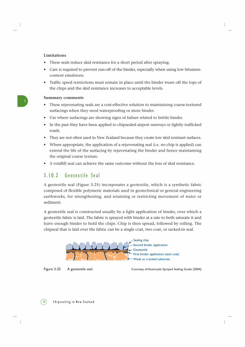
3 . 10 . 2 Geo t ex t i l e S e a l
A geotextile seal (Figure 3-25) incorporates a geotextile, which is a synthetic fabric
composed of flexible polymeric materials used in geotechnical or general engineering
earthworks, for strengthening, and retaining or restricting movement of water or
sediment.
A geotextile seal is constructed usually by a light application of binder, over which a
geotextile fabric is laid. The fabric is sprayed with binder at a rate to both saturate it and
leave enough binder to hold the chips. Chip is then spread, followed by rolling. The
chipseal that is laid over the fabric can be a single coat, two coat, or racked-in seal.
Figure 3-25 A geotextile seal. Courtesy of Austroads Sprayed Sealing Guide (2004)
Second binder applicationGeotextile
Weak or cracked substrate
First binder application (tack coat)
Sealing chip

3
75C h i p s e a l i n g i n N e w Z e a l a n d
Category
• First coat.
• Reseal.
When to use
• On soft, flushed or severely cracked pavements (Figure 3-26).
• To extend the life of a pavement by delaying the need for reconstruction.
• Used over a wet soft subgrade, such as a peat or sand.
• Also can be used to waterproof a bridge deck and restrict water from entering bridge
joints.
Existing surface condition required
• Used on a range of surface conditions.
• Designers use experience to determine the most appropriate chipseal type to use and
the construction method required.
Figure 3-26 Laying a geotextile on a cracked surface.Clockwise from top left: The cracked pavement to be treated. Top right: Laying the fabric over a bitumentack coat on the cracked pavement. Bottom right: the fabric in place. Bottom left: Saturating the fabricwith bitumen. The next step is to lay chip on top as for a conventional chipseal.
Photos courtesy of Julien van Dyk, The Isaac Construction Co. Ltd

3
76 C h i p s e a l i n g i n N e w Z e a l a n d
Advantages
• A strong, waterproof mat can be achieved which will cover cracked and stressed
surfaces.
• A geotextile seal has been shown in research by Towler & Ball (2001) to prevent future
flushing.
• Can be an economic alternative to reconstruction of a severely cracked pavement.
Limitations
• Geotextile seals can be costly in comparison to conventional seals.
• Success is very dependent on design and construction techniques. It is advisable to
follow the manufacturer’s recommendations.
• The seal can slide and move as a mat if not adhered to the underlying surface, especially
in situations of stresses caused by stopping and turning traffic.
• Geotextiles that incorporate a grid give limited strength benefit in surfacing applications.
• Geotextile seals of fabric-only type do not provide strength but do provide a medium
that allows increased binder thickness, suitable for repairing cracks and preventing
future flushing.
• When used on a flushed binder-rich surface, the fabric has the ability to absorb
binder. However, estimating the correct binder application rate so that the binder
is enough to hold the chipseal as well as saturate the fabric is very difficult.
Summary comments
• Geotextile seals incorporate the use of fabrics in the seal coat to enhance performance.
• They are used in specific circumstances and care is required in the surfacing design
and construction to ensure success.
• The fabric manufacturer’s instructions and industry best practice must be consulted
and followed in the construction of this type of seal.
• Applying the fabric evenly is difficult, with problems in areas that have many service
covers or corners. A specially built jig to hold and apply the fabric helps to alleviate
some of these problems, but these jigs are not common in New Zealand.
• Although some RCAs are reporting success with this technique, further research and
experience is required before it should be considered low risk.
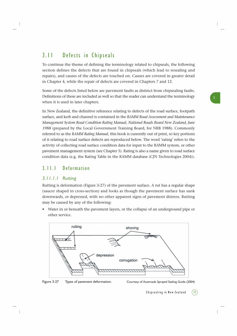
3
77C h i p s e a l i n g i n N e w Z e a l a n d
3 . 1 1 De f e c t s i n Ch i p s e a l sTo continue the theme of defining the terminology related to chipseals, the following
section defines the defects that are found in chipseals (which lead to resealing and
repairs), and causes of the defects are touched on. Causes are covered in greater detail
in Chapter 4, while the repair of defects are covered in Chapters 7 and 12.
Some of the defects listed below are pavement faults as distinct from chipsealing faults.
Definitions of these are included as well so that the reader can understand the terminology
when it is used in later chapters.
In New Zealand, the definitive reference relating to defects of the road surface, footpath
surface, and kerb and channel is contained in the RAMM Road Assessment and Maintenance
Management System Road Condition Rating Manual, National Roads Board New Zealand, June
1988 (prepared by the Local Government Training Board, for NRB 1988). Commonly
referred to as the RAMM Rating Manual, this book is currently out of print, so key portions
of it relating to road surface defects are reproduced below. The word ‘rating’ refers to the
activity of collecting road surface condition data for input to the RAMM system, or other
pavement management system (see Chapter 5). Rating is also a name given to road surface
condition data (e.g. the Rating Table in the RAMM database (CJN Technologies 2004)).
3 . 11 . 1 De f o rma t i o n
3.11.1.1 RuttingRutting is deformation (Figure 3-27) of the pavement surface. A rut has a regular shape
(saucer shaped in cross-section) and looks as though the pavement surface has sunk
downwards, or depressed, with no other apparent signs of pavement distress. Rutting
may be caused by any of the following:
• Water in or beneath the pavement layers, or the collapse of an underground pipe or
other service.
Figure 3-27 Types of pavement deformation. Courtesy of Austroads Sprayed Sealing Guide (2004)

3
78 C h i p s e a l i n g i n N e w Z e a l a n d
• Within-pavement densification, e.g. it can often be seen where excessive heavyvehicles have caused depressions in the wheelpaths. This would indicate pavementdeterioration and may be the normal end-of-design-life failure mode.
• As a result of construction faults, when it occurs in a relatively short time fromconstruction.
• Contamination or deterioration of the structural layer.
• As a result of subgrade deformation which is a structural weakness of the pavementlayer.
• When a deep layer of bitumen-rich surfacing has accumulated during the life of thepavement (although this usually results in shoving and shallow shear, see below).
To record the extent of rutting, the RAMM Rating Manual (NRB 1988) states:
the length of wheelpath which has rutted to a depth of 30 mm or greater as measuredfrom a 2 m straight edge placed across the wheelpath. If the whole carriageway area ora large part of it is shaped so it holds water then it is rated as if all the wheeltracks inthat area are rutted, e.g. for a two lane carriageway holding water over 20 m of theinspection length the rating for rutting would be 4 x 20 = 80 m.
Note that some RCAs require rating of ruts of as little as 20 mm depth.
The RAMM Rating Manual also states “Rutting has occurred when traffic has causedwheeltracks in the carriageway to be depressed with no bulging in the adjacent pavement.”
3.11.1.2 ShovingShoving, also called shallow shear, is deformation of the pavement surface where thepavement itself or just the surfacing layers have been deformed and misshapen, withaccompanying pavement distress such as alligator cracking, pumping or potholes.Figure 3-28 shows shoving, which may be caused by:
• water in or beneath the pavement layers;
• excessive shear stresses in the surfacing layers by heavy vehicles on corners;
• the disintegration of the granular basecourse layers of the pavement after excessiveand repetitive loading.
To record the extent of shoving, the RAMM Rating Manual states:
This rating records the length of wheelpath showing shoving in the inspection length.Where there are other defects in the length of shoving being rated, they are to be ignoredfor rating purposes; e.g. if both alligator cracking and potholes are present in a lengthof shoving, they would not be rated.
Shoving occurs when material is displaced to form a bulge or heave alongside the depressedarea… Shoving frequently occurs in the outside wheeltrack often as a result of poordrainage. It can also occur as the result of a poorly designed asphaltic concrete or as aresult of moisture entering the pavement through cracking.
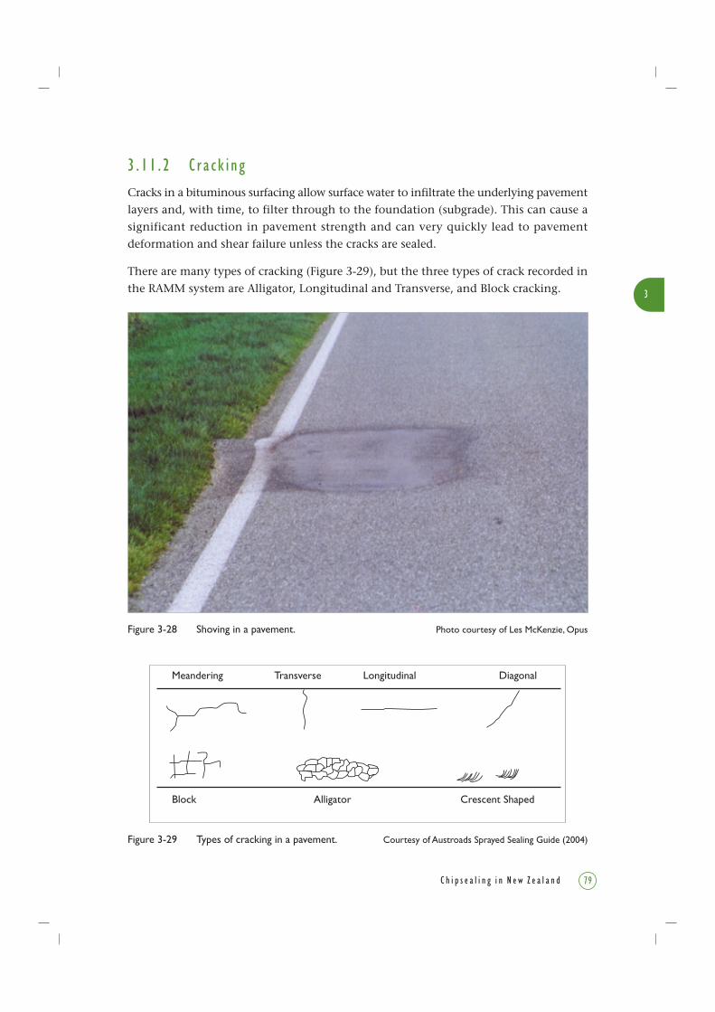
3
79C h i p s e a l i n g i n N e w Z e a l a n d
3 . 1 1 . 2 C r a c k i n g
Cracks in a bituminous surfacing allow surface water to infiltrate the underlying pavement
layers and, with time, to filter through to the foundation (subgrade). This can cause a
significant reduction in pavement strength and can very quickly lead to pavement
deformation and shear failure unless the cracks are sealed.
There are many types of cracking (Figure 3-29), but the three types of crack recorded in
the RAMM system are Alligator, Longitudinal and Transverse, and Block cracking.
Figure 3-28 Shoving in a pavement. Photo courtesy of Les McKenzie, Opus
Figure 3-29 Types of cracking in a pavement. Courtesy of Austroads Sprayed Sealing Guide (2004)
Meandering Transverse Longitudinal Diagonal
Block Alligator Crescent Shaped

3
80 C h i p s e a l i n g i n N e w Z e a l a n d
The crescent-shaped cracks in Figure 3-29 are caused by shear of the surfacing layers,
and the pavement would normally be rated as ‘shoved’ in New Zealand. The front of
the crack points in the direction of the traffic stream.
Alligator Cracking – so named for its semi-regular polyhedral shapes, reminiscent of the
pattern on an alligator’s skin (Figure 3-30). It is also know as chicken wire cracking as
it has the appearance of chicken wire mesh.
To record the extent of alligator cracking, the RAMM Rating Manual states:
This rating records the length of alligator (fatigue) cracking showing in the wheelpaths
of the carriageway…. Fine cracking often found at the edge of the seal is not to be rated
as alligator cracking. Alligator cracking is to include all polygon-shaped cracking irrespective
of the size of the polygons formed by the network of cracks.
Figure 3-30 Alligator cracking has a cracking pattern like an alligator skin.Photo courtesy of Les McKenzie, Opus

Figure 3-31 Longitudinal and transverse cracks run along or across the road.Photo courtesy of Les McKenzie, Opus
3
81C h i p s e a l i n g i n N e w Z e a l a n d
Alligator cracks are easiest to observe in the coldest months of the year as the surface
contracts and the cracks open up. After light rain the cracks are more obvious as the
surface dries leaving moisture in the cracks. If the rating survey is done over the summer
months then fine alligator cracks are much harder to see due to expansion of the
carriageway surface and glare off the surface. But looking into your shadow, cracks can
usually be observed.
Longitudinal and Transverse Cracks – long cracks that run along or across the road (also
includes diagonal and meandering cracks). This type of cracking (Figure 3-31) can occur
in overlays over cement-stabilised bases, and also in overlays over bituminous bases
wherever cracks in the old pavement have not been properly repaired, and this is known
as reflective cracking.
To record the extent of longitudinal and transverse cracking, the RAMM Rating Manual
states:
The rating for longitudinal and transverse cracks records the length of cracking in the
carriageway…. Large rectangular cracks are to be included as these are generally a more
severe form of longitudinal and transverse cracks which have extended sufficiently to
form a network.

3
82 C h i p s e a l i n g i n N e w Z e a l a n d
Block Cracking – cracks found, for example, around service covers (service holes, etc.)
where the rigid concrete mounting ends and the chipseal begins. Block cracking in thin
surfacing mixes may lead to alligator cracking. Block cracks are often caused by the
reflection of cracks in an underlying layer, e.g. from a cement-bound basecourse.
To record the extent of block cracking, the RAMM Rating Manual states:
This rating records the length of cracks present at joints in the surface of the pavement.
These cracks would typically be found at construction joints in asphaltic concrete or at
joints in the pavement surface where underground services have been laid.
Shrinkage Cracks – are not recorded in RAMM but can occur in very old bituminous
surfaces (especially in thin surfacing mixes) as a result of shrinkage. These shrinkage
cracks are not usually associated with pavement deterioration but, if left unsealed for
too long, moisture may filter through to the pavement foundation. This causes loss of
strength which may result in surface deformation. Shrinkage cracking can also occur
because tree roots have contracted, pulling the pavement during a drought, especially
alongside windbreaks.
3 . 11 . 3 Ch i p L o s s
3.11.3.1 ScabbingScabbing is chip loss from a chipseal. Chip loss may occur if there is not enough binder
or if the binder does not adhere to the chip (Figure 3-32) because the chip was wet, dirty,
or wetting and adhesion agents were not applied correctly. Chip loss can also occur on
older surfacing when the binder oxidises or becomes hard and looses its grip on the
chips. See Chapter 4 for discussion on causes of chip loss.
To record the extent of scabbing, the RAMM Rating Manual states:
This rating records the area of carriageway where the seal has lost more than 10% of
the sealing chip. In the case of asphaltic concrete surfaces, this is the area of pavement
showing signs of ravelling (surface attrition).
Scabbing occurs when sealing chips become separated from the bitumen in a chipseal.
In an asphaltic concrete pavement the aggregate loss from the mix is called ravelling and
is rated as scabbing.
3.11.3.2 RavellingRavelling is the loss of chip from an asphaltic concrete or a slurry surface. It occurs where
the binder has oxidised and is loosing its grip on the large- and small-sized aggregate of
the surfacing. In a way, the asphalt or slurry is unravelling. If it is not halted, ravelling
may cause deterioration to the extent that the surfacing mix no longer performs competently,
resulting in a lack of waterproofing, and it can cause an uncomfortable ride.

3
83C h i p s e a l i n g i n N e w Z e a l a n d
3 . 1 1 . 4 Po t h o l e s
Potholes are formed when the pavement surfacing is lost so that the underlying basecourse
is exposed (Figure 3-33). Often potholes become filled with water or even grass.
Figure 3-33 Potholes and cracks form where water gets under the pavement.Photo courtesy of Les McKenzie, Opus
Figure 3-32 Chip loss caused by dirty chip. Photo courtesy of Les McKenzie, Opus

3
84 C h i p s e a l i n g i n N e w Z e a l a n d
To record the extent of potholes, the RAMM Rating Manual states:
This rating records the number of potholes in the inspection length of carriageway.
A pothole is an area where the carriageway surface has deteriorated, resulting in the
cracking and eventual breaking up of the surface to form a cavity.
Pothole Repairs
These are small (usually asphaltic) patches over potholes that have been filled in (i.e.repaired) and are considered just as important an indication of pavement failure as thepotholes themselves. As repairs mean that the pavement surface has been compromised,the number of pothole repairs is counted along with potholes by the pavementmanagement system when determining the need for resurfacing.
To record the extent of pothole patches, the RAMM Rating Manual states:
The same criteria and ratings apply here as for potholes except that the holes have been
patched. A patch is to be rated as a pothole patch if it is less than 0.5 m2 in area. If a
patch is greater than 0.5 m2 it is to be considered part of the pavement.
3 . 11 . 5 Edg e B r e a k
Edge break is where the edge of the road has started to crack and fall away (especiallyon rural roads with unsealed shoulders). Edge break is defined when at least 100 mmof road edge has disappeared. It can leave a dangerous drop at the edge of the seal, andwheels of any vehicles that leave the road could become trapped over the side of theedge break, making it hard for the vehicle to easily make it back onto the carriageway.
To record the extent of edge break, the RAMM Rating Manual states:
This rating records the length of carriageway edge showing signs of edge break where
there is no surfaced channel. Edge break is the reduction of the seal coat by more than
100 mm from the original line of the seal edge. If a channel is present then any break
in the carriageway/channel boundary should be rated as ineffective surface water channel.
(Note: the topic of ‘ineffective surface water channel’ is not discussed in this book.)
Edge Break Repairs
To record the extent of edge break repair patches, the RAMM Rating Manual states:
… the same criteria and ratings apply here as for edge break except that the edge break
has been patched.
3 . 11 . 6 F l u s h i n g
Flushing creates a solid, smooth, black, slick surface caused by an excess of binder.Flushing may occur as the natural end-of-life condition of a well-designed chipseal, oras a seal design or construction fault. In hot weather a flushed surface may soften andbleed (Figure 3-34).
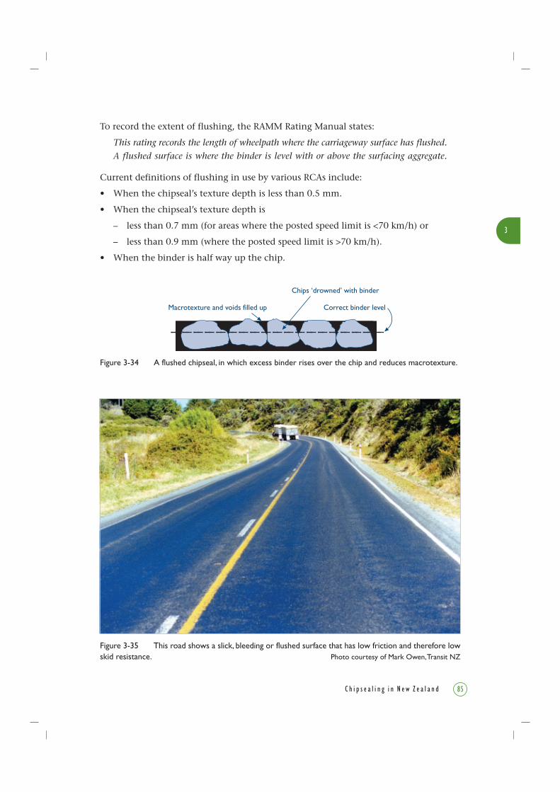
3
85C h i p s e a l i n g i n N e w Z e a l a n d
To record the extent of flushing, the RAMM Rating Manual states:
This rating records the length of wheelpath where the carriageway surface has flushed.
A flushed surface is where the binder is level with or above the surfacing aggregate.
Current definitions of flushing in use by various RCAs include:
• When the chipseal’s texture depth is less than 0.5 mm.
• When the chipseal’s texture depth is
– less than 0.7 mm (for areas where the posted speed limit is <70 km/h) or
– less than 0.9 mm (where the posted speed limit is >70 km/h).
• When the binder is half way up the chip.
Figure 3-34 A flushed chipseal, in which excess binder rises over the chip and reduces macrotexture.
Macrotexture and voids filled up
Chips ‘drowned’ with binder
Correct binder level
Figure 3-35 This road shows a slick, bleeding or flushed surface that has low friction and therefore lowskid resistance. Photo courtesy of Mark Owen, Transit NZ

3
86 C h i p s e a l i n g i n N e w Z e a l a n d
Figure 3-35 shows a slick bleeding or flushed surface that has low friction and therefore
low skid resistance. It is unacceptably slippery and unsafe as the tyres cannot grip the
sealing chip. Also the surface does not have any texture.
Insufficient binder causing areas of chip loss leads to exposed binder and thus to a slick
surface which is also classed as flushing.
3 . 11 . 7 B l e e d i n g
In hot weather when the binder is soft, it will adhere to the vehicle tyres and be spread
(tracked) over the surrounding road. This soft state is called bleeding and is undesirable
because the binder coats the microscopic surfaces of the chips (the microtexture), creating
a slick surface with a lowered skid resistance.
At a critical texture (which depends on chip size), the tyres can reach down into the
spaces between the chips and touch the surface of the binder. There is also a critical
viscosity (related to temperature and additives in the binder) at which the tyres are able
to adhere to the bitumen. Although tracked bleeding binder may eventually wear off
chips, it presents a hazard while it is present.
3 . 11 . 8 Roughn e s s
Roughness is a measure of the comfort of the ride (i.e. bumpiness of the road). Originally
it was measured with a ‘roughometer’ or NAASRA roughness response meter, which
literally counted the number of bumps recorded by a standard vehicle when it was
driven over a certain length of road. Today, roughness is more usually measured by a
set of lasers mounted on a vehicle, the data being analysed at the correct wavelength
to correspond to road bumps. (A different wavelength is analysed from the same data
to measure chip texture depth, and hence flushing.)
3 . 11 . 9 L o s s o f Tex t u r e
Loss of texture through flushing or other causes is measured by either sand circle
measurements (TNZ T/3:1981) or by High Speed Data (HSD) collection. The texture
output of HSD is the Mean Profile Depth (MPD). The principles of MPD measurement
are shown in Figure 3-36.
To remember the difference between flushing and bleeding, a flushed road surface
is solid in cold weather but may still bleed in hot weather.

3
87C h i p s e a l i n g i n N e w Z e a l a n d
3 . 1 1 . 10 Lo s s o f S k i d R e s i s t a n c eSkid resistance is measured as the wet-road skid resistance by the Sideway CoefficientRoutine Investigatory Machine (SCRIM). (SCRIM and skid resistance are explained inSection 4.9.) Low skid resistance recorded by SCRIM may have been caused by polishingof the chip or related to bleeding and flushing masking the microscopic surface of thechip (the microtexture).
3 . 1 1 . 1 1 C o n c l u s i o n
Shear failures (which cause shoving), depressions (rutting), and potholes form as a resultof pavement ageing and loss of waterproofing. As the pavement gets older, and weakeror softer because water is leaking into the underlying layers or is not draining away, itdeforms and the seal cracks, letting in more water which accelerates the damage.
Also the action of traffic causes pumping, which is the movement and ejection of fineparticles in suspension through joints or cracks. This removes fine particles from thebasecourse, which weakens it further, and the hydraulic pumping effect itself willeventually lift the seal.
To counter this natural deterioration, a well managed network will have a PavementManagement System in place for which the road condition rating data is collected andfed in, as described in Chapter 5. This means that the available budget is targeted toachieve the maximum return.
Figure 3-36 How the MPD (mean profile depth) is calculated from HSD (high speed data).
Peak level (1st)Mean Profile Depth (MPD)
Peak level (2nd)
Average level
(second half of baseline)(first half of baseline)
Baseline
Profile depth
Mean Profile Depth (MPD) = Peak level (1st) + Peak level (2nd)
– Average level2
3
88 C h i p s e a l i n g i n N e w Z e a l a n d
3 . 1 2 R e f e r e n c e s
Austroads. 2000. Guide to the selection of road surfacings. Austroads Publication
No. AP-63/00. 82pp. Austroads, Sydney, NSW.
Austroads. 2003. Guidelines and specification for bituminous slurry surfacing.
Austroads Publication No. AP-T26/03. 51pp. Austroads, Sydney, NSW.
Austroads. 2004. Pavement Design – A guide to the structural design of road
pavements. Austroads Publication No. AP-G17/04. Austroads, Sydney, NSW.
Austroads. 2004. Sprayed sealing guide. Austroads Publication No. AP-G76/04. 104pp.
Austroads, Sydney, NSW.
CJN Technologies. 2004. Software for RAMM. www.cjntech.co.nz
ISSA. 2004a. Recommended performance guidelines for emulsified asphalt slurry
seal. ISSA A105 (revised June 2004). International Slurry Surfacing Association,
Maryland, USA.
ISSA. 2004b. Recommended performance guidelines for micro-surfacing. ISSA A143
(revised June 2004). International Slurry Surfacing Association, Maryland, USA.
NZ PBCA (NZ Pavement & Bitumen Contractors’ Association Inc.). BCA E/2.
Specification for the performance of bitumen sprayers. NZ PBCA (now Roading NZ), PO
Box 12-412, Wellington.
NRB (National Roads Board). 1998. RAMM Road Assessment and Maintenance
Management System Road Condition Rating Manual. National Roads Board, June 1988.
Towler, J.I., Ball, G.F.A. 2001. Permeabilities of chipseals in New Zealand. Proceedings
of 20th ARRB Conference, Melbourne, 19-21 March 2001. 16pp.
Transit New Zealand. 1981. Standard test procedure for measurement of texture by
the sand circle method. TNZ T/3:1981.
Transit New Zealand. 1993. Bituminous sealing manual. 2nd edition. Transit NZ,
Wellington, New Zealand.

3
89C h i p s e a l i n g i n N e w Z e a l a n d
Transit New Zealand. 1997. Specification for general maintenance. TNZ C1 Addendum
No. 1:1997.
Transit New Zealand. 2002. Specification for sealing chip. TNZ M/6:2002.
Transit New Zealand. 2002. State Highway Maintenance Contract Proforma Manual
SMO32, Issue 2: March 2002.

90 C h i p s e a l i n g i n N e w Z e a l a n d