Embed Size (px)
Citation preview
© Parallax Inc. Rev 1.0
CHAPTER FIVE
Wrap Up And Near Space Qualifying "The good thing about standards
is there are so many to choose from." -Mark Caviezel and others
Chapter Objectives
1.0 Avionics Pallet ...................................................................................................... 1 2.0 Control Panel........................................................................................................ 5 3.0 Quad Panels and Booms........................................................................................ 9 4.0 Qualification Testing ........................................................................................... 23 5.0 Avoiding Problems .............................................................................................. 28 6.0 Failure Modes and Failure Analysis....................................................................... 32 Good to Know - The Flight of Explorer II (1935) ............................................................. 34
1.0 Avionics Pallet You can't just throw the Flight Computer along with the flight battery, radio, GPS, and TNC into a Styrofoam box and launch it. All avionics must be mounted securely inside the near space capsule so they are incapable of sliding around, bumping a switch, or pulling on a wire. Since avionics may need to be reorganized, do not permanently mount the avionics to the bottom of the near space capsule. Instead, mount the avionics to an avionics pallet and insert the pallet into the near spacecraft. A lightweight and easy to machine avionics pallet can be made from CoroplastA and StyrofoamB. For simple beacons and trackers, a single sheet of Coroplast is sufficient. When the avionics pallet incorporates multiple layers of electronics, use Styrofoam to add a third dimension to the pallet.
1.1. The Simple Avionics Pallet This pallet is designed for mounting the individual PCBs for trackers, beacons, or experiments to a durable, lightweight surface that prevents traces from being shorted out.
1.1.1. Parts List • Coroplast Sheet • Foamed Neoprene SheetC • Nylon Wire Ties (Zip ties)
1.1.2. Procedure The simple avionics pallet can mount a near space radio beacon to the back of an HT, or an entire flight computer into a near spacecraft. The construction method is identical, only the scale of the
Page 2 of 41 · Near Space Exploration with the BASIC Stamp by Paul Verhage
© Parallax Inc. Rev 1.0
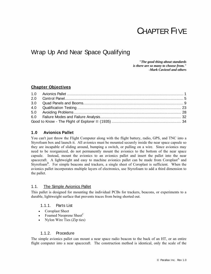
project changes. The neoprene foam cushions the PCB and fills gaps between the PCB and the Coroplast pallet. Nylon wire ties secure the PCB and neoprene to a sheet of Coroplast. This arrangement protects the underside of the PCB from shorts while still making it possible to get at the traces to fix a problem. Note: If the pallet is used to secure a near space beacon to an HT, then cut the Coroplast to fit the back of the HT and mount both the pallet and HT inside of a warm box. The warm box is primarily used to protect the HT buttons from being pushed during a mission. In this design, the beacon pallet can be rubber banded to the back of the HT. See Chapter Four, Section 4.2 for directions on making warm boxes.
Parts for an avionics pallet -Coroplast, neoprene foam, PCB, and nylon wire ties.
√ Cut a sheet of Coroplast to fit the airframe. √ Lay the foamed neoprene sheet under the PCB. √ Mark the size of the PCB and locations of its mounting holes. √ Carefully cut and punch holes into the neoprene. √ Lay the PCB on top of the Coroplast and mark the location of the mounting holes. √ Carefully punch the holes into the Coroplast (the sharp end of a file works well). √ Measure ½” away from the Coroplast holes and make a second set of holes that are outside
the edges of the PCB. √ Lay the PCB and neoprene on top of the Coroplast. √ Use nylon wire ties to tie the PCB down to the Coroplast. Orient the zip ties so that their
heads are above the Coroplast, and not beneath it. √ Lay the cables on the Coroplast and mark the location of holes for nylon wire tie strain
reliefs on the Coroplast. √ Carefully punch holes in the Coroplast and tie the cables down to the Coroplast as a strain
relief.

Chapter Five: Wrap Up And Near Space Qualifying · Page 3 of 41
© Parallax Inc. Rev 1.0
PBC on Coroplast – Zip ties hold the PCB to the Coroplast.
1.2. The Advanced Avionics Pallet When adding a larger board to the pallet, it may be advantageous to make the pallet in two layers. A large PCB, like a KPC 3+ TNC, is mounted to the bottom layer and a smaller PCB, like a flight computer, is mounted to the top layer. Make sure the bottom mounted item is a device seldom needing access. Keep frequently accessed boards on the top surface of the pallet.
Advanced Avionics Pallet - The completed two-layer avionics pallet.
1.2.1. Parts List Same as a simple Avionics Pallet, plus:
Page 4 of 41 · Near Space Exploration with the BASIC Stamp by Paul Verhage
© Parallax Inc. Rev 1.0
• #6-32 mounting hardware (nuts, bolts, washers) • Blue or Pink Styrofoam • Hot glue
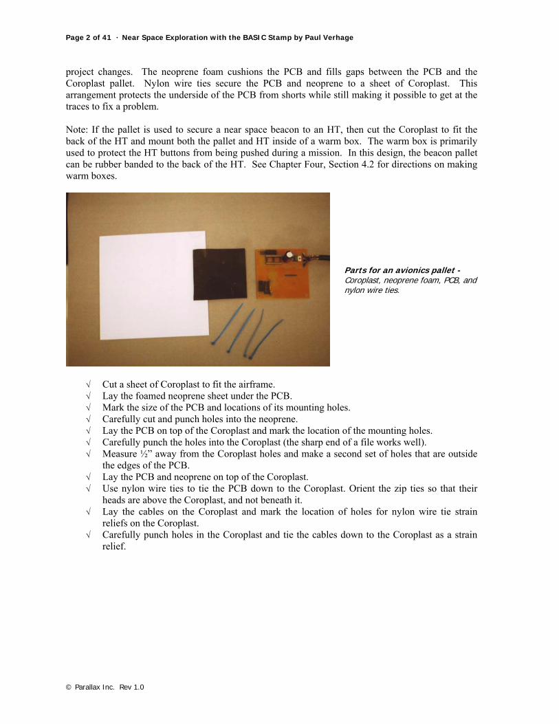
1.2.2. Procedure √ Begin by determining which boards will be mounted to the top and bottom layers of the
avionics pallet. Be sure to place boards that need infrequent access on the bottom layer. √ Position and orient boards for the bottom layer. √ Cut Styrofoam to form a wall around the border of the bottom layer. Note: make the border
thick enough that #6 mounting hardware can pass through it and high enough to raise the top layer above the board.
√ Use hot glue to adhere the Styrofoam wall to the bottom layer of Coroplast. √ Place the top Coroplast layer on top of the bottom layer and drill holes for the #6 bolts. √ Bolt the top of the pallet to the bottom to test the fit (use washers under the bolt head and
nut). √ Separate the two layers if they fit properly.
Completed pallet - The two layer avionics pallet, opened.
√ Lay foamed neoprene sheet under the bottom PCB. √ Mark the size of the PCB and locations of its mounting holes. √ Carefully cut and punch holes into the neoprene. √ Lay the bottom PCB on top of the bottom Coroplast and mark the location of the mounting
holes. √ Carefully punch the holes into the bottom Coroplast (the sharp end of a file works well). √ Measure ½” away from the bottom Coroplast holes and make a second set of holes that are
outside the edges of the PCB. √ Lay the PCB and neoprene on top of the bottom Coroplast. √ Use nylon wire ties to tie the PCB down to the bottom Coroplast. √ Orient the zip ties so that their heads are above the bottom Coroplast, and not beneath it. √ Lay the cables on the bottom Coroplast and mark the location of holes for nylon wire tie
strain reliefs on the Coroplast. √ Cut channels into the Styrofoam wall to pass the bottom PCB cables through. √ Repeat the same process for the top PCB(s) and the top Coroplast.
Chapter Five: Wrap Up And Near Space Qualifying · Page 5 of 41
© Parallax Inc. Rev 1.0
2.0 Control Panel
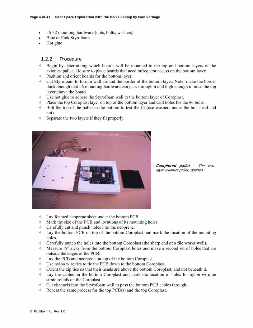
Completed control panel – shown with avionics pallet.
The airframe’s Control Panel (which is mounted to the P3 port of the airframe) provides central access to all programming and power functions of the avionics pallet. Each avionics pallet has its own Control Panel and they move as a unit from airframe to airframe. The Control Panel is mounted to the inside surface of the airframe and a polystyrene frame is mounted to the outside, sandwiching the airframe foam between them. The polystyrene frame acts a washer, keeping the airframe foam from being crushed by the nut and washer of the #6 hardware.
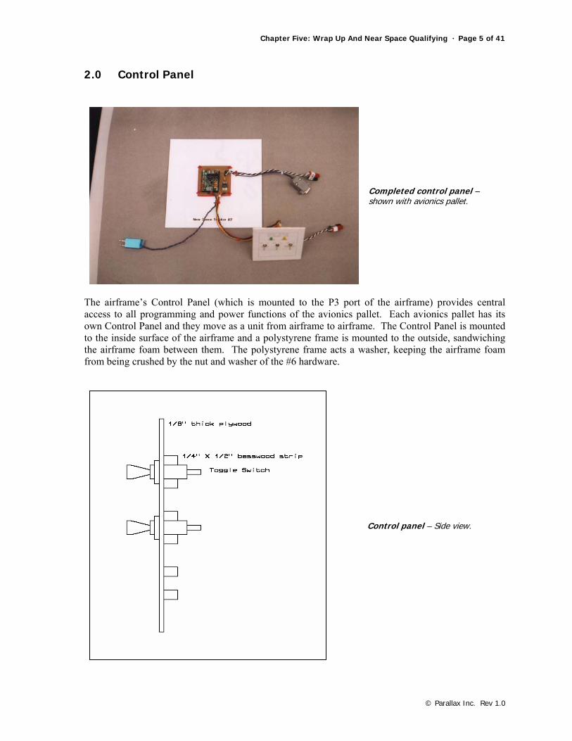
Control panel – Side view.
Page 6 of 41 · Near Space Exploration with the BASIC Stamp by Paul Verhage
© Parallax Inc. Rev 1.0
[side diagram of control panel]
2.1. Materials • 1/8” or 1/16” plywood • 30-mil thick polystyrene • Paper Label * • ¼” square basswood dowel • Spiral wire wrap • Two toggle switches (used as spacers when assembling the Control Panel) • #6 mounting hardware (nuts, bolts, and washers) • #1 mounting hardware (nuts, bolts, and washers) to fit DB-9 connector • Model Paint and Sticky Colored Dots ** • White glue • Wood glue • Hot glue • Clear paint (dull coat)
* Print a label with a word processor. Organize switch functions, programming headers, and power-on LEDs and then surround the text in the appropriate size box. A set of sample labels is included in the appendix. When designing the paper label, make the ON and OFF directions consistent for all Control Panels and clearly label the ON and OFF directions. There’s almost nothing worse than going to launch only to find the batteries were discharged the night before because someone left the NEAR SPACECRAFT on all night. See Appendix D for examples of Control Panel faces. ** This is optional. The paint is applied to the top ¼” rail of the Control Panel and the sticky dots are applied to one side of the toggle switches. Make the paint and sticky dots the same color. If used, by aligning the paint and dots, the toggle switches are aligned properly in their rails to match the ON and OFF directions indicated on the Control Panel.
2.1.1. Procedure √ Cut a piece of 1/8" or 1/16” plywood to cover the P3 Port with enough border to attach the
plate with four #6 bolts (1/2” border all the way around). √ Cut a square out of the polystyrene to dimensions that match the Control Panel.
Chapter Five: Wrap Up And Near Space Qualifying · Page 7 of 41
© Parallax Inc. Rev 1.0
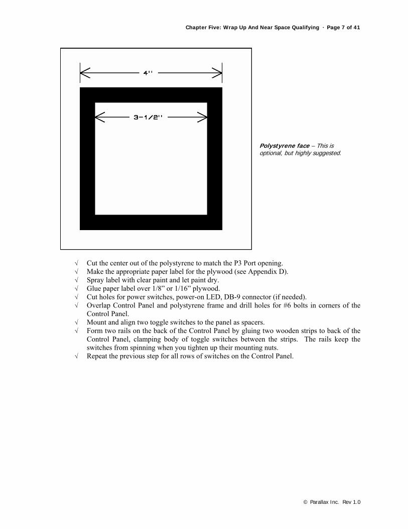
Polystyrene face – This is optional, but highly suggested.
√ Cut the center out of the polystyrene to match the P3 Port opening. √ Make the appropriate paper label for the plywood (see Appendix D). √ Spray label with clear paint and let paint dry. √ Glue paper label over 1/8” or 1/16” plywood. √ Cut holes for power switches, power-on LED, DB-9 connector (if needed). √ Overlap Control Panel and polystyrene frame and drill holes for #6 bolts in corners of the
Control Panel. √ Mount and align two toggle switches to the panel as spacers. √ Form two rails on the back of the Control Panel by gluing two wooden strips to back of the
Control Panel, clamping body of toggle switches between the strips. The rails keep the switches from spinning when you tighten up their mounting nuts.
√ Repeat the previous step for all rows of switches on the Control Panel.
Page 8 of 41 · Near Space Exploration with the BASIC Stamp by Paul Verhage
© Parallax Inc. Rev 1.0
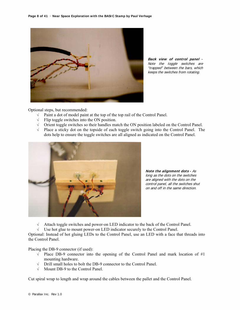
Back view of control panel - Note the toggle switches are “trapped” between the bars, which keeps the switches from rotating.
Optional steps, but recommended:
√ Paint a dot of model paint at the top of the top rail of the Control Panel. √ Flip toggle switches into the ON position. √ Orient toggle switches so their handles match the ON position labeled on the Control Panel. √ Place a sticky dot on the topside of each toggle switch going into the Control Panel. The
dots help to ensure the toggle switches are all aligned as indicated on the Control Panel.
Note the alignment dots - As long as the dots on the switches are aligned with the dots on the control panel, all the switches shut on and off in the same direction.
√ Attach toggle switches and power-on LED indicator to the back of the Control Panel. √ Use hot glue to mount power-on LED indicator securely to the Control Panel.
Optional: Instead of hot gluing LEDs to the Control Panel, use an LED with a face that threads into the Control Panel. Placing the DB-9 connector (if used):
√ Place DB-9 connector into the opening of the Control Panel and mark location of #1 mounting hardware.
√ Drill small holes to bolt the DB-9 connector to the Control Panel. √ Mount DB-9 to the Control Panel.
Cut spiral wrap to length and wrap around the cables between the pallet and the Control Panel.
Chapter Five: Wrap Up And Near Space Qualifying · Page 9 of 41
© Parallax Inc. Rev 1.0
3.0 Quad Panels and Booms
3.1. Quad Panels Quad panels cover the open quad ports of the airframe. Experiments or antenna booms are mounted to them. Together with a NearSys CC/PS, they form a modular near space system that can be moved from launch to launch, or module to module. Quad panels are mounted to the exterior of the airframe with #6 bolts, washers, and nuts. A polystyrene plate is mounted to the inside surface to act as a washer. The airframe side is sandwiched between the panel and plate.
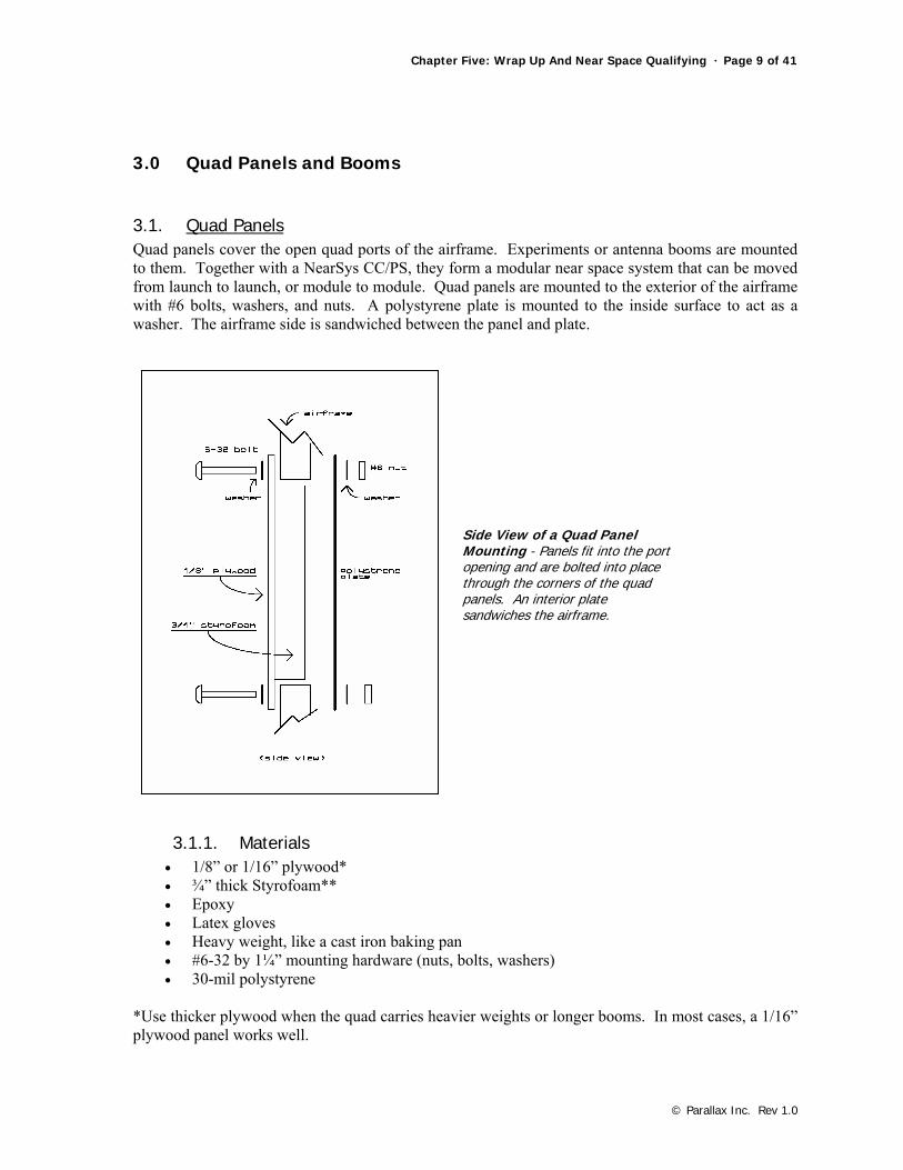
Side View of a Quad Panel Mounting - Panels fit into the port opening and are bolted into place through the corners of the quad panels. An interior plate sandwiches the airframe.
3.1.1. Materials • 1/8” or 1/16” plywood* • ¾” thick Styrofoam** • Epoxy • Latex gloves • Heavy weight, like a cast iron baking pan • #6-32 by 1¼” mounting hardware (nuts, bolts, washers) • 30-mil polystyrene
*Use thicker plywood when the quad carries heavier weights or longer booms. In most cases, a 1/16” plywood panel works well.
Page 10 of 41 · Near Space Exploration with the BASIC Stamp by Paul Verhage
© Parallax Inc. Rev 1.0
** You should have kept the Styrofoam panels you cut out of the airframe when you were constructing it.
3.1.2. Procedure These directions assume the airframe is designed as illustrated in Chapter One, Airframes. Note on cutting Styrofoam: Use a long-bladed Exacto knife and a straight edge. It’s time to replace the dull blade when your Styrofoam begins to chip, rather than cut cleanly.
√ Cut out a new Styrofoam panel or trim the one that was removed from the airframe during its construction. Cut or trim the panel to a dimension of 5-1/8” on a side.
√ Verify the Styrofoam panel easily slides in and out of the open quad port of the airframe. √ Cut the plywood into a square with sides 6” long. √ Lay the plywood panel smooth-face down, as you are going to epoxy on its rough face. √ Put on a pair of latex gloves. √ Mix up epoxy and apply to one face of the Styrofoam panel. √ Center the Styrofoam over the plywood and epoxy the two together. √ Apply masking tape between the Styrofoam and plywood to keep the Styrofoam from
sliding. √ Add weight on top and let sit for one hour.
√ Remove weight and tape. √ Test fit panel in airframe. √ Drill out 1/8” diameter holes through the plywood and in the corners of the Styrofoam. √ Test fit panel again, this time using #6 hardware to bolt the panel into the port.
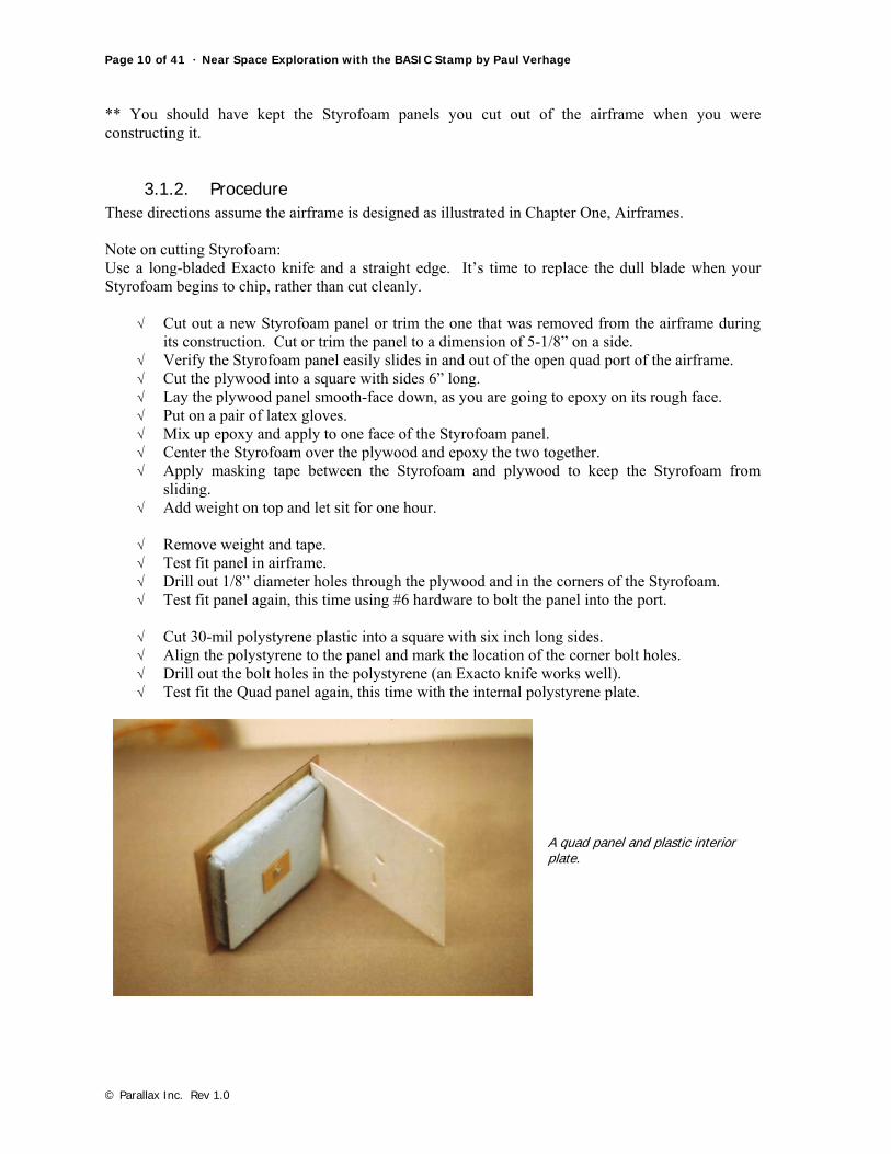
√ Cut 30-mil polystyrene plastic into a square with six inch long sides. √ Align the polystyrene to the panel and mark the location of the corner bolt holes. √ Drill out the bolt holes in the polystyrene (an Exacto knife works well). √ Test fit the Quad panel again, this time with the internal polystyrene plate.
A quad panel and plastic interior plate.

Chapter Five: Wrap Up And Near Space Qualifying · Page 11 of 41
© Parallax Inc. Rev 1.0
Usually a boom or other experiment is mounted to the Quad Panel. Often these require other openings through the Quad Panel for cables to pass through. The same size hole must be made in the plastic plate and in the same location. It would be a good idea to give this some thought and determine a single location and size for these pass-through holes. This allows any polystyrene plate to be used with any Quad Panel. If the location and size of pass-through holes is not standardized, then a new polystyrene plate must be made for each new Quad Panel (even with the adoption of a standard, there will be instances when a Quad Panel needs a specific plate). Do not drill the pass-through if the Quad Panel is to have a boom; instead wait until after the boom is epoxied to the Quad Panel. A CD holder and booms are examples of items added to a Quad Panel.
3.2. CD Holder
CD-ROM holder - Anyone remember Voyager I and II’s gold record?
Remember Voyager 1 and 2? How about Carl Sagan’s gold phonograph record? Amateur near space explorers can do a similar thing with CDs. A CD with text and images in web format carried on a near space flight is a wonderful way to commemorate an event or program. The directions below explain how to safely mount a CD to a Quad Port in a fashion that makes it visible on the near spacecraft.
3.2.1. Materials • Completed Quad Panel • 1/16” plywood • 1/8” plywood • #6 mounting hardware (nut bolt, and two washers) • Epoxy • Very thin plastic sheet
Page 12 of 41 · Near Space Exploration with the BASIC Stamp by Paul Verhage
© Parallax Inc. Rev 1.0
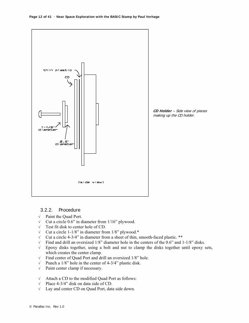
CD Holder – Side view of pieces making up the CD holder.
3.2.2. Procedure √ Paint the Quad Port. √ Cut a circle 0.6” in diameter from 1/16” plywood. √ Test fit disk to center hole of CD. √ Cut a circle 1-1/8” in diameter from 1/8” plywood.* √ Cut a circle 4-3/4” in diameter from a sheet of thin, smooth-faced plastic. ** √ Find and drill an oversized 1/8” diameter hole in the centers of the 0.6” and 1-1/8” disks. √ Epoxy disks together, using a bolt and nut to clamp the disks together until epoxy sets,
which creates the center clamp. √ Find center of Quad Port and drill an oversized 1/8” hole. √ Punch a 1/8” hole in the center of 4-3/4” plastic disk. √ Paint center clamp if necessary.
√ Attach a CD to the modified Quad Port as follows: √ Place 4-3/4” disk on data side of CD. √ Lay and center CD on Quad Port, data side down.
Chapter Five: Wrap Up And Near Space Qualifying · Page 13 of 41
© Parallax Inc. Rev 1.0
√ Insert center clamp into CD center, sandwiching CD between Quad Port and center clamp. The 4-3/4” disk protects the data surface of the CD from abrasion and exposure to UV in near space. CDs sent into near space in this fashion were unaffected by their trip. Note: A stack of CDs can be launched into near space if the center clamp is made deeper. * A plastic or metal disk is also appropriate. ** The diameter of a CD.
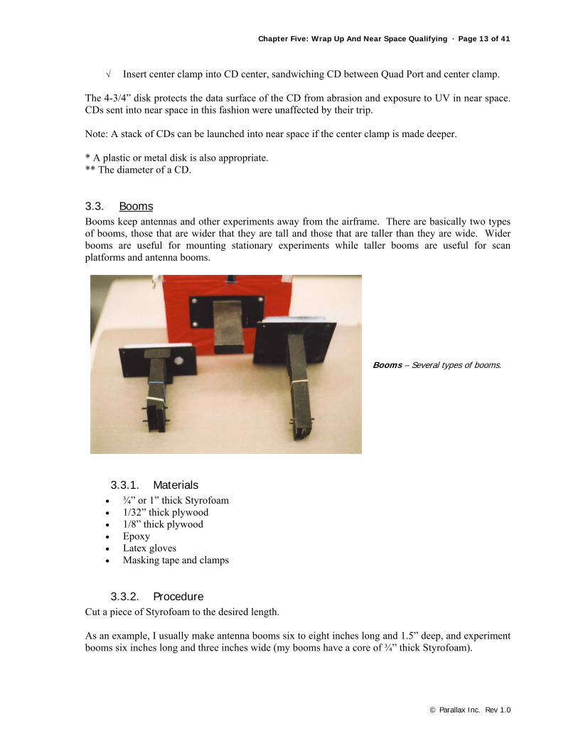
3.3. Booms Booms keep antennas and other experiments away from the airframe. There are basically two types of booms, those that are wider that they are tall and those that are taller than they are wide. Wider booms are useful for mounting stationary experiments while taller booms are useful for scan platforms and antenna booms.
Booms – Several types of booms.
3.3.1. Materials • ¾” or 1” thick Styrofoam • 1/32” thick plywood • 1/8” thick plywood • Epoxy • Latex gloves • Masking tape and clamps
3.3.2. Procedure Cut a piece of Styrofoam to the desired length. As an example, I usually make antenna booms six to eight inches long and 1.5” deep, and experiment booms six inches long and three inches wide (my booms have a core of ¾” thick Styrofoam).
Page 14 of 41 · Near Space Exploration with the BASIC Stamp by Paul Verhage
© Parallax Inc. Rev 1.0
√ Lay the largest side of the boom on a sheet of 1/32” plywood and draw two outlines of the boom.
√ Add a 1/8” border to the outline and cut the plywood with a knife of scissors.* √ Mark the rough side of each plywood piece with pencil (this side is epoxied) √ Put on a pair of latex gloves. √ Mix up epoxy and glue the plywood to two opposite sides of the boom. √ Use strips of tape and clamps to press the plywood to the boom until the epoxy sets
√ After the epoxy sets, remove the clamp and tape. √ Sand the Styrofoam and plywood to size on a sanding belt. √ Epoxy two more pieces to the bare sides of the boom by repeating the above steps. √ After the epoxy sets, sand the plywood faces to meet properly at their edges.
√ Epoxy 1/8” thick plywood to one end of the boom (do not epoxy plywood to the other end of
the boom). √ After the epoxy sets, sand the plywood face to meet properly at its edges
√ Cut “triangles” of 1/8” thick plywood to form braces for the boom √ Test fit the boom and braces √ Epoxy the open end of the boom to a Quad Panel; make sure the boom is perpendicular to
the Quad Panel. √ Use masking tape and a clamp to secure the boom and brace as the epoxy sets. √ Drill out the pass-through after the epoxy sets.
* Do not use your best scissors for this.
3.4. Modifications to Booms The following three modifications illustrate how antennas, servos, and long extensions are added to booms.
3.4.1. Modifications for Experiment Mounting Booms Wide booms are useful for mounting experiments outside the airframe. The experiment is either bolted or rubber banded to the boom. The following design is for a generic experiment boom, suitable for a wide variety of experiments.

Chapter Five: Wrap Up And Near Space Qualifying · Page 15 of 41
© Parallax Inc. Rev 1.0
Experiment Boom - A wide boom makes a convenient location to mount experiments. Secure experiments with bolts or rubber bands.
Materials
• 1/8” plywood • Two Popsicle sticks • Epoxy • #6 mounting hardware (nuts, bolts, and washers)
Procedure
√ Cut a doubler for the boom from 1/8” plywood, making its dimensions equal to the bottom surface of the boom.
√ Mark the 1/8” on its rough side, the side that will be epoxied to the boom. √ Epoxy the double to the bottom of the boom and clamp until the epoxy sets. √ Drill a set of two 1/8” holes the length of the boom, centered on the boom. √ Cut two Popsicle sticks to one inch longer than the width of the boom. √ Epoxy the sticks to the underside of the boom, between mounting holes. √ Paint the boom.
Future experiments are either bolted to the holes in the boom, or are rubber banded to the boom with the Popsicle sticks. Rubber bands start at the Popsicle sticks, around the experiment, then to the Popsicle stick on the other side of the boom.
3.4.2. Modification for an Antenna Boom The following steps complete a boom for a dipole antenna (as described in Chapter Four, Section Three).
Page 16 of 41 · Near Space Exploration with the BASIC Stamp by Paul Verhage
© Parallax Inc. Rev 1.0
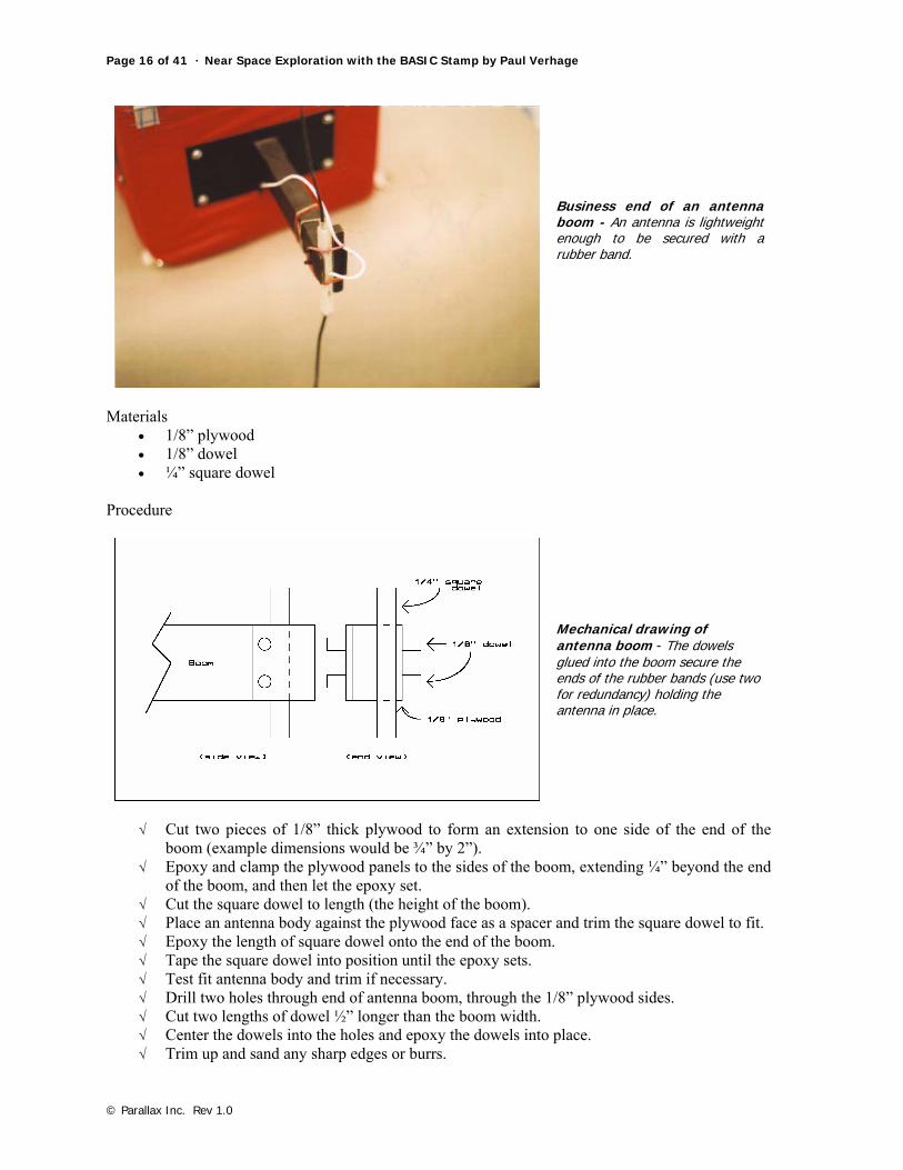
Business end of an antenna boom - An antenna is lightweight enough to be secured with a rubber band.
Materials
• 1/8” plywood • 1/8” dowel • ¼” square dowel
Procedure
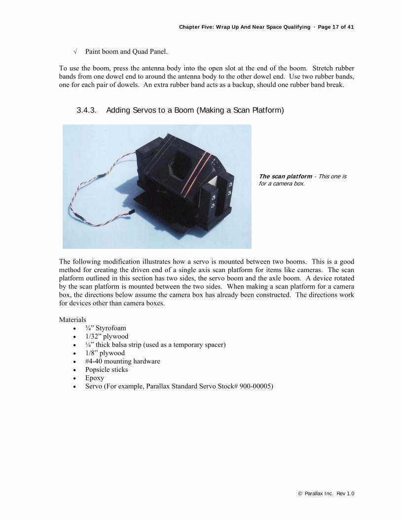
Mechanical drawing of antenna boom - The dowels glued into the boom secure the ends of the rubber bands (use two for redundancy) holding the antenna in place.
√ Cut two pieces of 1/8” thick plywood to form an extension to one side of the end of the boom (example dimensions would be ¾” by 2”).
√ Epoxy and clamp the plywood panels to the sides of the boom, extending ¼” beyond the end of the boom, and then let the epoxy set.
√ Cut the square dowel to length (the height of the boom). √ Place an antenna body against the plywood face as a spacer and trim the square dowel to fit. √ Epoxy the length of square dowel onto the end of the boom. √ Tape the square dowel into position until the epoxy sets. √ Test fit antenna body and trim if necessary. √ Drill two holes through end of antenna boom, through the 1/8” plywood sides. √ Cut two lengths of dowel ½” longer than the boom width. √ Center the dowels into the holes and epoxy the dowels into place. √ Trim up and sand any sharp edges or burrs.
Chapter Five: Wrap Up And Near Space Qualifying · Page 17 of 41
© Parallax Inc. Rev 1.0
√ Paint boom and Quad Panel. To use the boom, press the antenna body into the open slot at the end of the boom. Stretch rubber bands from one dowel end to around the antenna body to the other dowel end. Use two rubber bands, one for each pair of dowels. An extra rubber band acts as a backup, should one rubber band break.
3.4.3. Adding Servos to a Boom (Making a Scan Platform)
The scan platform - This one is for a camera box.
The following modification illustrates how a servo is mounted between two booms. This is a good method for creating the driven end of a single axis scan platform for items like cameras. The scan platform outlined in this section has two sides, the servo boom and the axle boom. A device rotated by the scan platform is mounted between the two sides. When making a scan platform for a camera box, the directions below assume the camera box has already been constructed. The directions work for devices other than camera boxes. Materials
• ¾” Styrofoam • 1/32” plywood • ¼” thick balsa strip (used as a temporary spacer) • 1/8” plywood • #4-40 mounting hardware • Popsicle sticks • Epoxy • Servo (For example, Parallax Standard Servo Stock# 900-00005)
Page 18 of 41 · Near Space Exploration with the BASIC Stamp by Paul Verhage
© Parallax Inc. Rev 1.0
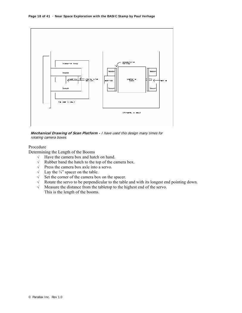
Mechanical Drawing of Scan Platform - I have used this design many times for rotating camera boxes.
Procedure Determining the Length of the Booms
√ Have the camera box and hatch on hand. √ Rubber band the hatch to the top of the camera box. √ Press the camera box axle into a servo. √ Lay the ¼” spacer on the table. √ Set the corner of the camera box on the spacer. √ Rotate the servo to be perpendicular to the table and with its longest end pointing down. √ Measure the distance from the tabletop to the highest end of the servo.
This is the length of the booms.
Chapter Five: Wrap Up And Near Space Qualifying · Page 19 of 41
© Parallax Inc. Rev 1.0
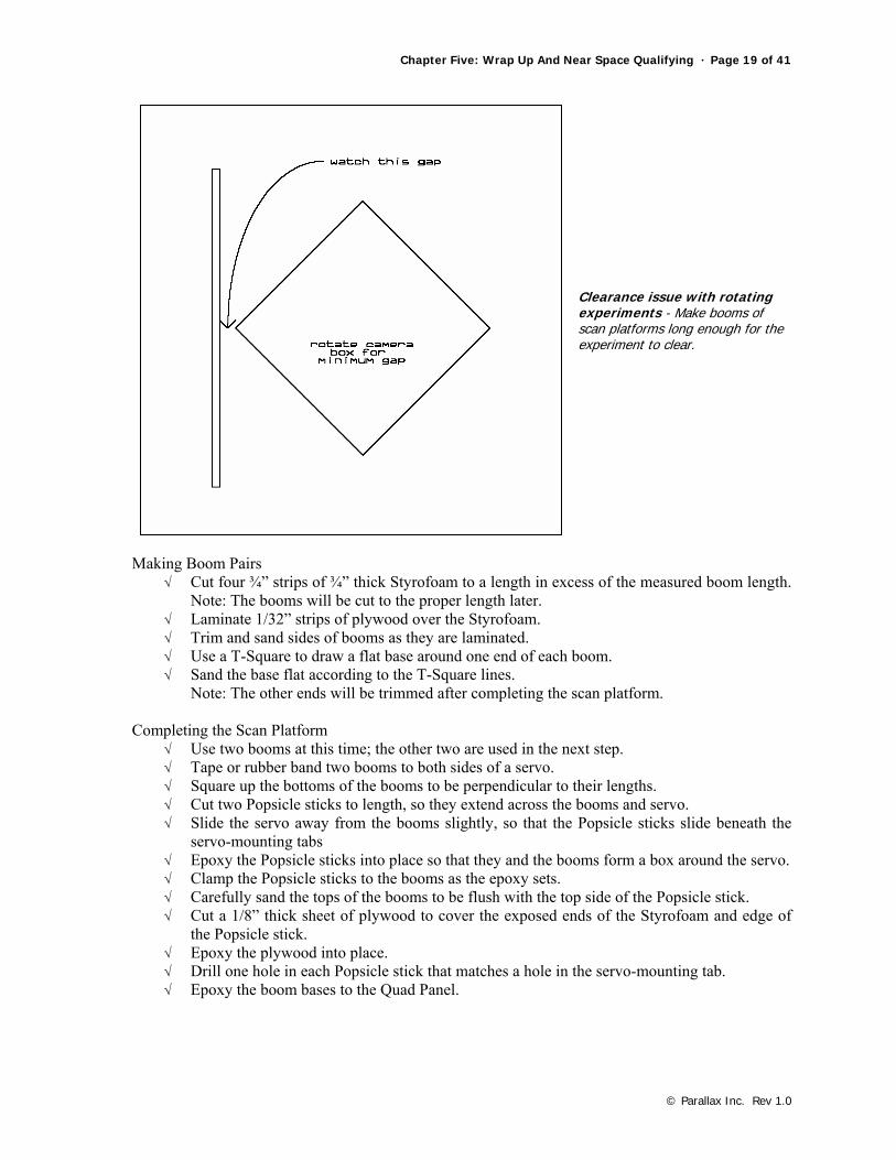
Clearance issue with rotating experiments - Make booms of scan platforms long enough for the experiment to clear.
Making Boom Pairs
√ Cut four ¾” strips of ¾” thick Styrofoam to a length in excess of the measured boom length. Note: The booms will be cut to the proper length later.
√ Laminate 1/32” strips of plywood over the Styrofoam. √ Trim and sand sides of booms as they are laminated. √ Use a T-Square to draw a flat base around one end of each boom. √ Sand the base flat according to the T-Square lines.
Note: The other ends will be trimmed after completing the scan platform. Completing the Scan Platform
√ Use two booms at this time; the other two are used in the next step. √ Tape or rubber band two booms to both sides of a servo. √ Square up the bottoms of the booms to be perpendicular to their lengths. √ Cut two Popsicle sticks to length, so they extend across the booms and servo. √ Slide the servo away from the booms slightly, so that the Popsicle sticks slide beneath the
servo-mounting tabs √ Epoxy the Popsicle sticks into place so that they and the booms form a box around the servo. √ Clamp the Popsicle sticks to the booms as the epoxy sets. √ Carefully sand the tops of the booms to be flush with the top side of the Popsicle stick. √ Cut a 1/8” thick sheet of plywood to cover the exposed ends of the Styrofoam and edge of
the Popsicle stick. √ Epoxy the plywood into place. √ Drill one hole in each Popsicle stick that matches a hole in the servo-mounting tab. √ Epoxy the boom bases to the Quad Panel.
Page 20 of 41 · Near Space Exploration with the BASIC Stamp by Paul Verhage
© Parallax Inc. Rev 1.0
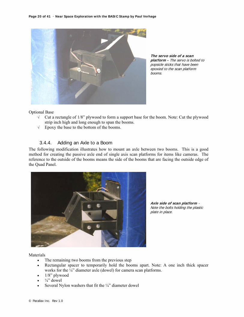
The servo side of a scan platform - The servo is bolted to popsicle sticks that have been epoxied to the scan platform booms.
Optional Base
√ Cut a rectangle of 1/8” plywood to form a support base for the boom. Note: Cut the plywood strip inch high and long enough to span the booms.
√ Epoxy the base to the bottom of the booms.
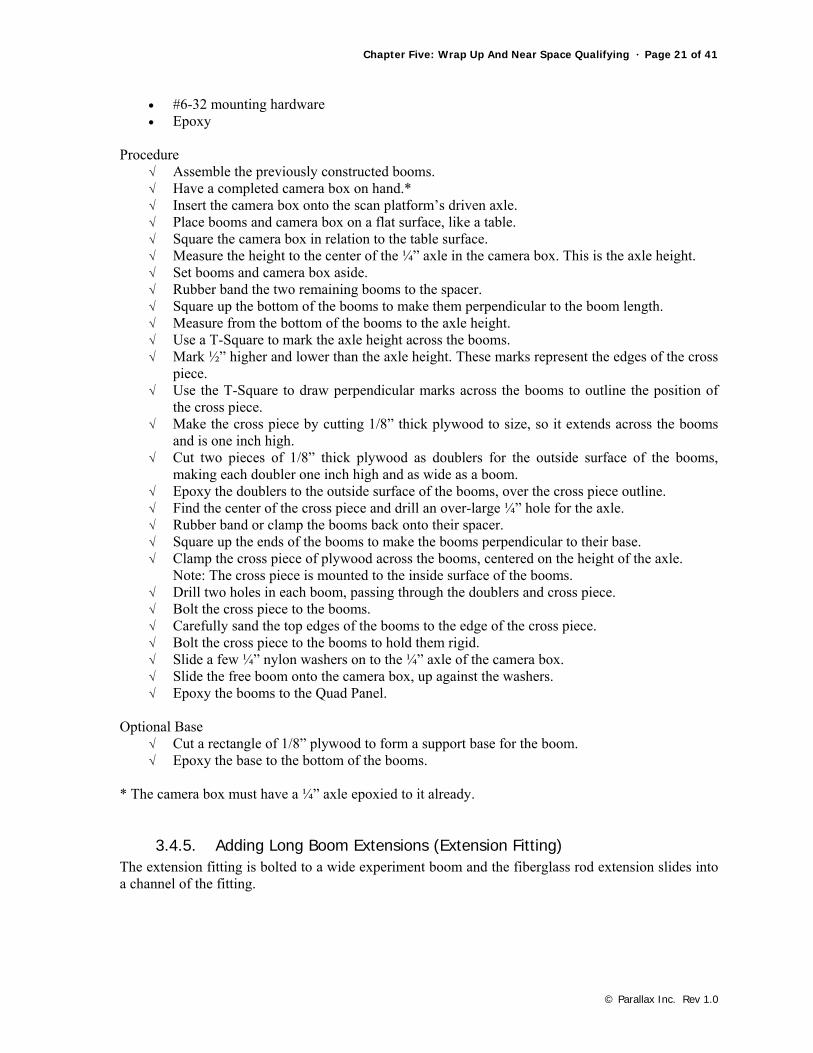
3.4.4. Adding an Axle to a Boom The following modification illustrates how to mount an axle between two booms. This is a good method for creating the passive axle end of single axis scan platforms for items like cameras. The reference to the outside of the booms means the side of the booms that are facing the outside edge of the Quad Panel.
Axle side of scan platform - Note the bolts holding the plastic plate in place.
Materials
• The remaining two booms from the previous step • Rectangular spacer to temporarily hold the booms apart. Note: A one inch thick spacer
works for the ¼” diameter axle (dowel) for camera scan platforms. • 1/8” plywood • ¼” dowel • Several Nylon washers that fit the ¼” diameter dowel
Chapter Five: Wrap Up And Near Space Qualifying · Page 21 of 41
© Parallax Inc. Rev 1.0
• #6-32 mounting hardware • Epoxy
Procedure
√ Assemble the previously constructed booms. √ Have a completed camera box on hand.* √ Insert the camera box onto the scan platform’s driven axle. √ Place booms and camera box on a flat surface, like a table. √ Square the camera box in relation to the table surface. √ Measure the height to the center of the ¼” axle in the camera box. This is the axle height. √ Set booms and camera box aside. √ Rubber band the two remaining booms to the spacer. √ Square up the bottom of the booms to make them perpendicular to the boom length. √ Measure from the bottom of the booms to the axle height. √ Use a T-Square to mark the axle height across the booms. √ Mark ½” higher and lower than the axle height. These marks represent the edges of the cross
piece. √ Use the T-Square to draw perpendicular marks across the booms to outline the position of
the cross piece. √ Make the cross piece by cutting 1/8” thick plywood to size, so it extends across the booms
and is one inch high. √ Cut two pieces of 1/8” thick plywood as doublers for the outside surface of the booms,
making each doubler one inch high and as wide as a boom. √ Epoxy the doublers to the outside surface of the booms, over the cross piece outline. √ Find the center of the cross piece and drill an over-large ¼” hole for the axle. √ Rubber band or clamp the booms back onto their spacer. √ Square up the ends of the booms to make the booms perpendicular to their base. √ Clamp the cross piece of plywood across the booms, centered on the height of the axle.
Note: The cross piece is mounted to the inside surface of the booms. √ Drill two holes in each boom, passing through the doublers and cross piece. √ Bolt the cross piece to the booms. √ Carefully sand the top edges of the booms to the edge of the cross piece. √ Bolt the cross piece to the booms to hold them rigid. √ Slide a few ¼” nylon washers on to the ¼” axle of the camera box. √ Slide the free boom onto the camera box, up against the washers. √ Epoxy the booms to the Quad Panel.
Optional Base
√ Cut a rectangle of 1/8” plywood to form a support base for the boom. √ Epoxy the base to the bottom of the booms.
* The camera box must have a ¼” axle epoxied to it already.
3.4.5. Adding Long Boom Extensions (Extension Fitting) The extension fitting is bolted to a wide experiment boom and the fiberglass rod extension slides into a channel of the fitting.

Page 22 of 41 · Near Space Exploration with the BASIC Stamp by Paul Verhage
© Parallax Inc. Rev 1.0
Extension Boom
Materials
• 1/8” plywood • ¼” square rod • Epoxy • #6 mounting hardware (nuts, bolts, and washers) • ¼” fiberglass dowel (the type used in kite spars)
Mechanical drawing of extension boom - Friction holds the boom in place.
Procedure
√ Cut a piece of 1/8” plywood to fit the width of the boom and a length of 4.5”. √ Cut a second piece of 1/8” plywood the same width and a length of 3”. √ Draw a line down the center of the 3” length of plywood. √ Cut four 3” lengths of ¼” square rods. √ Epoxy two of the square dowels centered and to the outside edges of the 4.5” length of
plywood and clamp until the epoxy sets. √ Place the fiberglass rod along the center of the 4.5” plywood as a spacer and epoxy the
remaining two square rods against the sides of the fiberglass rod. √ Remove the fiberglass spacer and clamp the square rods in place. √ Remove the clamps and test fit the fiberglass rod; it should slide in the center channel
formed by the inner two square rods. √ Apply epoxy to the tops of the square rods and clamp the 3” length of plywood on top. √ Drill 1/8” holes into the 4.5” plywood (bottom of extension fitting) to match four holes in
the experiment boom.
Chapter Five: Wrap Up And Near Space Qualifying · Page 23 of 41
© Parallax Inc. Rev 1.0
√ Test fit the extension fitting by bolting it to the experiment boom and sliding the fiberglass rod into the center channel.
√ Paint the extension fitting.
3.4.6. Notes on Using Extension Booms • Lightweight experiments are preferable for the ends of long booms. • Hot glue adheres Coroplast housing to fiberglass booms. • Do not let cables or wires dangle from the booms; tie the wires down to the boom for the
length of the boom. • Use wire zip ties or short lengths of heat shrink tubing to tie wires to booms. • Do not permanently glue fiberglass booms to extension fittings; the extension boom must be
free to pull out before breaking the experiment boom. • Leave a few inches of slack wire at the base of the boom and extension fitting to prevent
wires from breaking or binding if the boom extension pulls out.
4.0 Qualification Testing A new near spacecraft must be tested before its first launch. The cost of the flight and hardware is too great to risk sending a capsule that may fail thirty minutes into a three-hour flight. The goal of Qualification Testing (QT) is twofold: ● Ensure the capsule is reliable for a near space flight. ● Determine the nominal flight values and symptoms of failures. In the first case you are attempting to make sure the capsule will not fail during a typical flight (ensuring flight reliability), and in the second case you are determining the symptoms of an impending failure in flight (useful in failure analysis). To meet these two goals of QT I have designed three sets of tests. The first set of tests ensures the capsule is functioning properly and determines nominal values for avionics. The second set of tests ensures events during a flight will not lead to an in-flight failure. The third set of tests determines the symptoms of failure
4.1. Capsule Function, Nominal Values, and Calibration The five tests in this section check that the capsule powers up properly, determines a nominal value for current, calibrates the flight battery voltages, calibrates interior temperatures and determines the extent of self-heating inside the capsule, and determines the nominal percentage of dropped packets. I strongly encourage these tests be performed, especially if this is your first near spacecraft.
4.1.1. Proper Power Up and Function The first test determines that the avionics do not contain a short or open and that the BS2p in the flight computer is programmable in-circuit. Basically you cannot proceed to the next tests unless the first test is successful. Procedure Install a fully charged flight battery and power up the near space capsule. There should be no smoke, fire, or sparks emitted by the near space capsule. If testing the CC/PS, download a sample program and verify that the program downloaded properly and that debug data is being received.
Page 24 of 41 · Near Space Exploration with the BASIC Stamp by Paul Verhage
© Parallax Inc. Rev 1.0
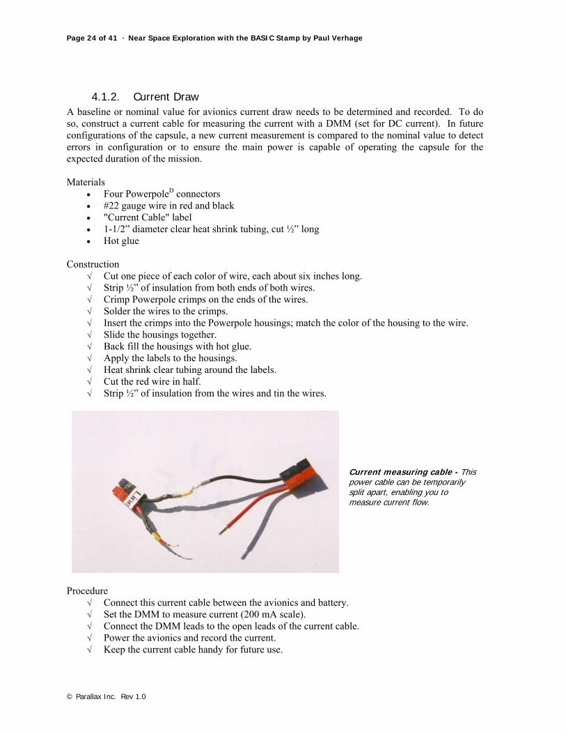
4.1.2. Current Draw A baseline or nominal value for avionics current draw needs to be determined and recorded. To do so, construct a current cable for measuring the current with a DMM (set for DC current). In future configurations of the capsule, a new current measurement is compared to the nominal value to detect errors in configuration or to ensure the main power is capable of operating the capsule for the expected duration of the mission. Materials
• Four PowerpoleD connectors • #22 gauge wire in red and black • "Current Cable" label • 1-1/2” diameter clear heat shrink tubing, cut ½” long • Hot glue
Construction
√ Cut one piece of each color of wire, each about six inches long. √ Strip ½” of insulation from both ends of both wires. √ Crimp Powerpole crimps on the ends of the wires. √ Solder the wires to the crimps. √ Insert the crimps into the Powerpole housings; match the color of the housing to the wire. √ Slide the housings together. √ Back fill the housings with hot glue. √ Apply the labels to the housings. √ Heat shrink clear tubing around the labels. √ Cut the red wire in half. √ Strip ½” of insulation from the wires and tin the wires.
Current measuring cable - This power cable can be temporarily split apart, enabling you to measure current flow.
Procedure
√ Connect this current cable between the avionics and battery. √ Set the DMM to measure current (200 mA scale). √ Connect the DMM leads to the open leads of the current cable. √ Power the avionics and record the current. √ Keep the current cable handy for future use.
Chapter Five: Wrap Up And Near Space Qualifying · Page 25 of 41
© Parallax Inc. Rev 1.0
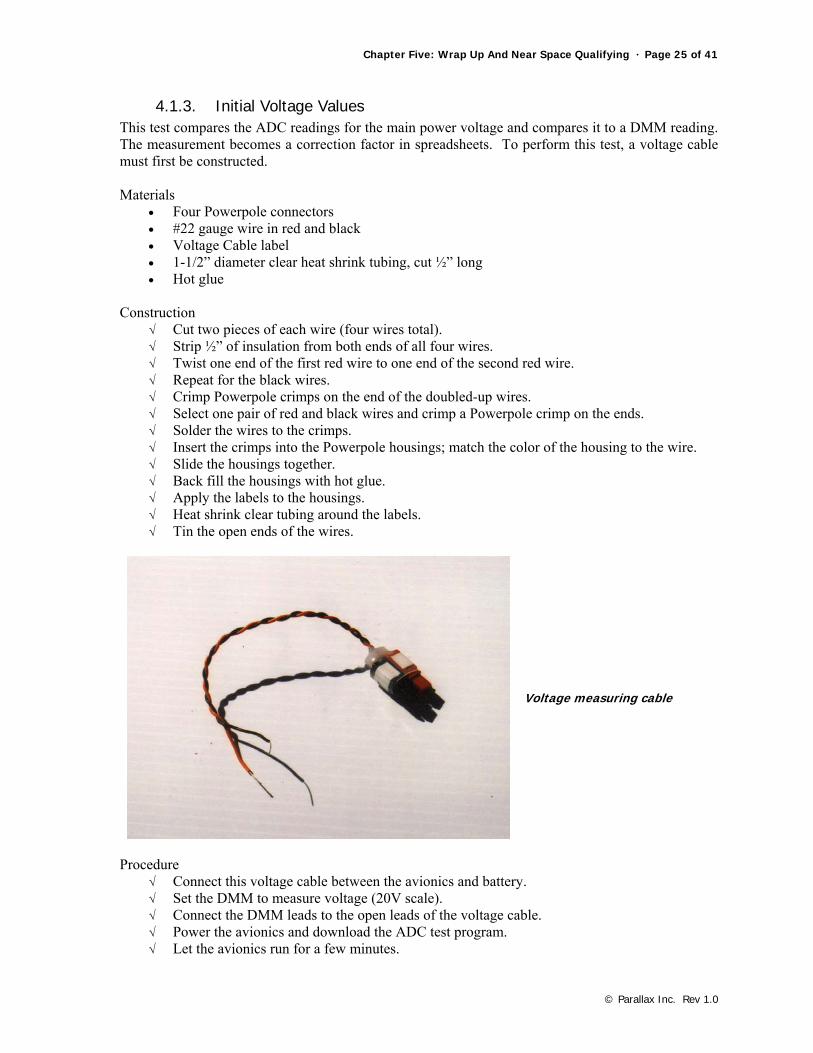
4.1.3. Initial Voltage Values This test compares the ADC readings for the main power voltage and compares it to a DMM reading. The measurement becomes a correction factor in spreadsheets. To perform this test, a voltage cable must first be constructed. Materials
• Four Powerpole connectors • #22 gauge wire in red and black • Voltage Cable label • 1-1/2” diameter clear heat shrink tubing, cut ½” long • Hot glue
Construction
√ Cut two pieces of each wire (four wires total). √ Strip ½” of insulation from both ends of all four wires. √ Twist one end of the first red wire to one end of the second red wire. √ Repeat for the black wires. √ Crimp Powerpole crimps on the end of the doubled-up wires. √ Select one pair of red and black wires and crimp a Powerpole crimp on the ends. √ Solder the wires to the crimps. √ Insert the crimps into the Powerpole housings; match the color of the housing to the wire. √ Slide the housings together. √ Back fill the housings with hot glue. √ Apply the labels to the housings. √ Heat shrink clear tubing around the labels. √ Tin the open ends of the wires.
Voltage measuring cable
Procedure
√ Connect this voltage cable between the avionics and battery. √ Set the DMM to measure voltage (20V scale). √ Connect the DMM leads to the open leads of the voltage cable. √ Power the avionics and download the ADC test program. √ Let the avionics run for a few minutes.
Page 26 of 41 · Near Space Exploration with the BASIC Stamp by Paul Verhage
© Parallax Inc. Rev 1.0
√ Record the voltage and ADC reading. √ Make measurements at several battery voltages and record the voltage and ADC reading.
Enter the recorded voltages and corresponding ADC values into a spreadsheet. A graph of the data should be linear. Calculate the slope of the line and the y-intercept of ADC values versus main power voltages for a spreadsheet formula. Keep the voltage cable handy for future use.
4.1.4. Internal Temperatures This test debugs the ADC value of the internal temperature for comparison to the measurements taken by a thermometer. After watching the temperature for an hour, any tendency of the capsule to self-heat is also determined (which is not as important as the initial calibration). Procedure Place a thermometer inside the airframe and seal the capsule. Power up the capsule and download the ADC test program. After several minutes open the airframe and measure the interior temperature with the thermometer and compare this measurement to the ADC value. Watch the temperature over one hour and record every few minutes. Determine the average temperature and whether the capsule self-heats.
4.1.5. Missed Packets The final test determines the percentage of skipped packets from the Flight Computer or Tracker that can be expected. This test involves sending telemetry from a flight computer or tracker and verifying that both that GPS sentences can be read and be telemetered. Take the near spacecraft outside where the GPS antenna can "see" satellites. Procedure If testing a flight computer, then download the telemetry test program. Otherwise, just attach the GPS to the tracker or TNC. Switch the HT frequency away from the national APRS frequency (144.390) so the test does not interfere with legitimate packet traffic. Power up the capsule outside where the GPS receiver can see satellites. Watch packet telemetry on a PC. You want to make sure the TNC is properly transmitting telemetry. Look at the raw GPS data; make sure a GPS fix exists and that the TNC is not reporting old data. Confirm that the GPS is reporting the correct altitude. Do not be alarmed when all TNC packets do not get through. Determine what is nominal for the capsule. You may want to take the capsule for a test drive and record its packets throughout the test.
4.2. Event Testing Now that the capsule is confirmed to operate and its nominal values and calibration data are recorded, test the capsule for its ability to function through the events of a near space flight. In some ways, these tests are less important that the previous tests, but should still be completed if this is your first near spacecraft.
4.2.1. Shake Test Burst is chaotic. The capsule shakes and bounces around during the descent. Pack a capsule as if it were going on a mission and give it good shake. The capsule’s avionics should function normally
Chapter Five: Wrap Up And Near Space Qualifying · Page 27 of 41
© Parallax Inc. Rev 1.0
during the test. During a typical landing, the capsule lands at a speed of about 1200 feet/minute or 20 feet/second. According to what we learned in high school physics, a speed of 20 feet/second is generated when an object falls for 0.6 seconds under the acceleration due to gravity. In a descent of 0.6 seconds, the same object falls five feet. Therefore a drop from five feet simulates a descent speed of 1200 feet/minute. If you want to simulate the landing of the capsule on the avionics, then drop the capsule from a height of five feet above the lawn (most flights recovery in open fields rather than cement sidewalks). Perform this test without booms in place, as they do not need to be tested. The capsule should not stop operating after landing. To be honest with you, I don’t have the nerve to attempt this test, but my near spacecraft experiences this on every flight.
4.2.2. Recovery Test Read Chapter Six, Section 5.1 for directions on testing near spacecraft (and parachutes) during recovery.
4.2.3. Thermal Testing Remove the avionics from the airframe and seal them (including the batteries) into a clear plastic bag along with a thermometer. The bag is to prevent condensation, which can foul the thermal test. The antenna is too large to seal inside, so tape around the opening in the bag for the antenna coax. Be sure to seal the bag in a dry environment. First refrigerate the sealed avionics for a couple of hours. Immediately after removing from the refrigerator, confirm the GPS is capable of achieving a satellite lock and the TNC and HT are transmitting. If the avionics are reporting the temperature, compare the ADC reading to the thermometer reading. Typically, the airframe interior temperature stays above freezing during a flight, except possibly during the early descent. The next test chills the avionics to a lower temperature and confirms it works at the worst expected temperature. Repeat sealing the avionics and batteries inside a clear plastic bag, along with a thermometer. Again, leave the antenna outside the bag. Place the sealed avionics inside the freezer compartment and chill for thirty minutes. Remove the avionics and confirm the GPS is able to get a satellite lock and the TNC and HT are transmitting telemetry. If the telemetry is sending the avionics temperature, compare the reading to that of the thermometer. It was during just such as test that Jeff Melanson (KD7INN) discovered a failure concerning the Etrex GPS receiver. When its batteries cool down too far, the Etrex shuts down.
4.3. Failure Symptoms The next three tests, a cold test, a brownout test, and a GPS test, will operate the avionics to more extreme conditions. A well-insulated airframe is unlikely to fail the cold test, so it can be skipped if desired. The brownout/blackout test is more important and yields important results. The final test, GPS lock failure, shouldn’t occur in near space, but it’s handy to have a record of the symptoms.
4.3.1. Chill to Kill Pack the airframe inside a plastic bag to avoid condensation problems (near space is very dry). Pack the airframe inside a large Styrofoam cooler with blocks of dry ice. Protect the capsule from direct contact with dry ice by wrapping the dry ice in a cloth towel. Telemetry from the capsule can be
Page 28 of 41 · Near Space Exploration with the BASIC Stamp by Paul Verhage
© Parallax Inc. Rev 1.0
received outside the Styrofoam box during this test. Monitor telemetry and determine if the ultra cold of dry ice causes a failure. These temperatures are about the most extreme you can expect for a flight.
4.3.2. Brown-outs And Black-outs This test runs the batteries down. The results from this test indicate two things: what events to expect as the avionics begin to fail, and an estimate of how long a near spacecraft is expected to function during a flight. One thing to notice is that when the voltage to the flight computer or tracker’s microcontroller drops too low, it undergoes a brownout. BASIC Stamp modules contain a brownout circuit which protects the microcontroller from behaving erratically or corrupting memory when the voltage drops too low. The last thing we want is for a flight computer to go on a rampage because of a low voltage condition (just imagine the results if this occurred in a Boe-Bot). When a brownout occurs, the BASIC Stamp module shuts down and reduces the load on the flight battery. With the reduced load, the flight battery voltage rises high enough to restart the module, which pulls the voltage back down to brownout conditions. This occurs until the flight battery is drained low enough that the voltage cannot rise high enough to restart the BASIC Stamp. Eventually the BASIC Stamp module experiences a blackout and shuts down completely. The occurrence of a brownout can be determined when a BASIC Stamp restarts several times in quick succession at the beginning of its stored program. Frequent resets during a flight are a bad sign. Begin this test with a fully charged set of batteries. Record the start time and record the telemetry log from the avionics. Record the time the first brownout occurs and the time the BASIC Stamp module shuts down with a blackout. Record the ADC voltage reading when brownouts begin. Multiply the measured current draw from test 4.1.2 by the time required to reach brownout. The result determines the capacity the batteries under that current load. Record this result, as it is needed in section 5.2.
4.3.3. Lost GPS Lock Cover the GPS antenna with a sheet of aluminum foil. Record the results in telemetry. The important field to look at is the number of satellites in the $GPGGA sentence. How does the calculated GPS position change as satellite locks are lost?
5.0 Avoiding Problems The following list of suggestions will reduce the chances of an in-flight failure. However, the list is not comprehensive. Experience will permit you to develop a more complete checklist.
5.1. Suspend Time with a Complete Near Spacecraft (sans balloon) Assemble the modules into a complete capsule, along with the recovery system. Suspend the near spacecraft from a tree or balcony by a strong cord. Power up the avionics and observe the telemetry. Verify there is no there a problem with clearance between the modules and their antennas. Also verify there is no problem with radio frequency interference (RFI) among the components.
Chapter Five: Wrap Up And Near Space Qualifying · Page 29 of 41
© Parallax Inc. Rev 1.0
5.2. Check the Current Again The nominal current for the avionics was determined and recorded during test 4.1.2. After the near spacecraft is configured for its next mission, measure the current again. Does the current seem excessive? Divide the capacity of the flight batteries (calculated in test 4.3.2) by the measured current to estimate how long the capsule can function under this configuration. If it won’t last the entire flight, then do not launch the near spacecraft. Reconfigure the flight or determine if there is a bad component.
5.3. Proper Treatment of Batteries Some cells must be stored in a charged state while others must be stored in a discharged state. Know the requirements of the chemistry of the flight batteries and store the cells properly. Keep cells from freezing or getting too hot before launch. The assembled capsule can be stored in a cold location the night before a launch, but the batteries need to be kept at home and brought to the launch that morning. Be sure to properly recharge flight cells. As an example, do not recharge NiCds unless they have been fully discharged. Also, do not discharge cells to a voltage lower than is recommended for their chemistry. Test the cell voltage after charging and again in the capsule once the capsule is powered up. If using rechargeable cells, bring an extra set of charged cells to the launch site as a backup.
5.4. Shielding and RF Problems The full-up test of Section 5.1 will ensure there is no RFI. To further guard against RFI, cover HTs with boxes covered in aluminum or copper tape. From the author’s experience, the DJ-S11 does not appear to create a RFI problem. To be safe, shield any untested transmitter (like an ATV transmitter). Various types of aluminum and copper tape are available for this purpose. Other options include physically moving the transmitter or its antenna to a new location (e.g. separate module) or reducing the transmitter power.
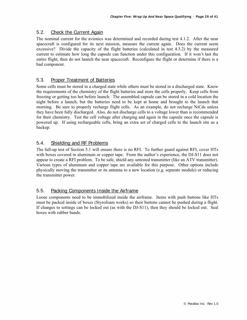
5.5. Packing Components Inside the Airframe Loose components need to be immobilized inside the airframe. Items with push buttons like HTs must be packed inside of boxes (Styrofoam works) so their buttons cannot be pushed during a flight. If changes to settings can be locked out (as with the DJ-S11), then they should be locked out. Seal boxes with rubber bands.
Page 30 of 41 · Near Space Exploration with the BASIC Stamp by Paul Verhage
© Parallax Inc. Rev 1.0
An HT and its warm box - More important than warmth, this box ensures HT buttons are not pressed during a mission.
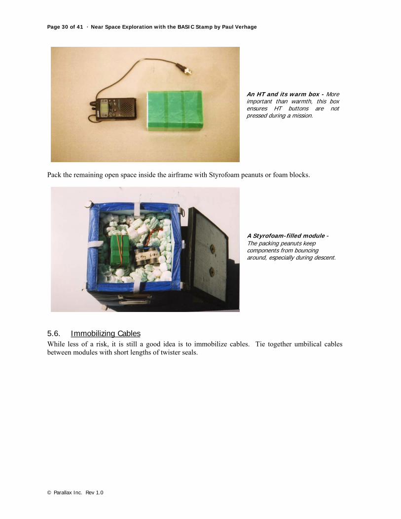
Pack the remaining open space inside the airframe with Styrofoam peanuts or foam blocks.
A Styrofoam-filled module - The packing peanuts keep components from bouncing around, especially during descent.
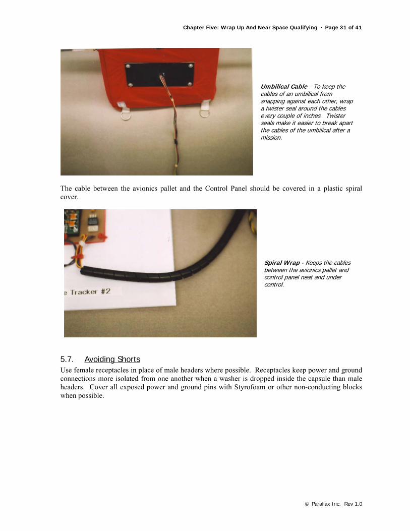
5.6. Immobilizing Cables While less of a risk, it is still a good idea is to immobilize cables. Tie together umbilical cables between modules with short lengths of twister seals.
Chapter Five: Wrap Up And Near Space Qualifying · Page 31 of 41
© Parallax Inc. Rev 1.0
Umbilical Cable - To keep the cables of an umbilical from snapping against each other, wrap a twister seal around the cables every couple of inches. Twister seals make it easier to break apart the cables of the umbilical after a mission.
The cable between the avionics pallet and the Control Panel should be covered in a plastic spiral cover.
Spiral Wrap - Keeps the cables between the avionics pallet and control panel neat and under control.
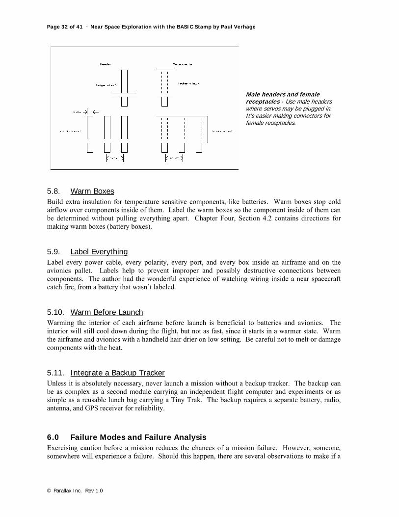
5.7. Avoiding Shorts Use female receptacles in place of male headers where possible. Receptacles keep power and ground connections more isolated from one another when a washer is dropped inside the capsule than male headers. Cover all exposed power and ground pins with Styrofoam or other non-conducting blocks when possible.
Page 32 of 41 · Near Space Exploration with the BASIC Stamp by Paul Verhage
© Parallax Inc. Rev 1.0
Male headers and female receptacles - Use male headers where servos may be plugged in. It’s easier making connectors for female receptacles.
5.8. Warm Boxes Build extra insulation for temperature sensitive components, like batteries. Warm boxes stop cold airflow over components inside of them. Label the warm boxes so the component inside of them can be determined without pulling everything apart. Chapter Four, Section 4.2 contains directions for making warm boxes (battery boxes).
5.9. Label Everything Label every power cable, every polarity, every port, and every box inside an airframe and on the avionics pallet. Labels help to prevent improper and possibly destructive connections between components. The author had the wonderful experience of watching wiring inside a near spacecraft catch fire, from a battery that wasn’t labeled.
5.10. Warm Before Launch Warming the interior of each airframe before launch is beneficial to batteries and avionics. The interior will still cool down during the flight, but not as fast, since it starts in a warmer state. Warm the airframe and avionics with a handheld hair drier on low setting. Be careful not to melt or damage components with the heat.
5.11. Integrate a Backup Tracker Unless it is absolutely necessary, never launch a mission without a backup tracker. The backup can be as complex as a second module carrying an independent flight computer and experiments or as simple as a reusable lunch bag carrying a Tiny Trak. The backup requires a separate battery, radio, antenna, and GPS receiver for reliability.
6.0 Failure Modes and Failure Analysis Exercising caution before a mission reduces the chances of a mission failure. However, someone, somewhere will experience a failure. Should this happen, there are several observations to make if a
Chapter Five: Wrap Up And Near Space Qualifying · Page 33 of 41
© Parallax Inc. Rev 1.0
mission should fail during a flight. The results are compared to the record from the previous tests performed in this chapter. Here are a couple of things to look for in a failure.
6.1. Cold Convert temperature ADC measurements into interior temperatures. Did the interior temperature drop lower than expected, or to the point of battery failure? The results of tests performed in sections 4.2.3 and 4.3.1 indicate the border between acceptable and unacceptable temperatures. If it appears lower temperatures are responsible for a flight failure, the avionics may restart after landing when the interior temperature comes back up. It’s important that someone drive back to the predicted recovery zone and listen for telemetry from the near spacecraft.
6.2. Dead Batteries Graph ADC voltage readings. Determine if the batteries discharged sooner than expected. This is a symptom of a short circuit or improperly recharged batteries. To reduce the chances of this occurring, measure the current draw of the assembled capsule and measure the voltage of the batteries under a load, once the capsule as been powered up. Look for evidence in the telemetry for the flight computer restarting itself as a result of a brownout. Compare main power voltage to interior temperature. As cells chill, their voltage drops. A drop in temperature may be the factor causing a drop in main power voltage.
6.3. Short Circuits Look for a dramatic rise in battery voltage and possibly a rise in the airframe’s interior temperature. A drop in voltage should follow the voltage spike. But the batteries may completely fail as their voltage drops, preventing the transmission of main power telemetry. Placing a temperature sensor inside the battery compartment is a good idea. If the cells shorted out, there may be a temperature spike in the cells that the temperature sensor can report.
6.4. Lost GPS Lock Become familiar with GPS sentences so you can read the TNC log in APRS. In fact, start doing this from the first flight, even if it does not fail. Evaluate the GPS sentences by looking at fields like number of satellites, or the time UTC. When a GPS receiver begins to lose a lock, the number of satellites drops and eventually the time UTC field is left blank. The GPS receiver requires the largest amount of current, so look at the ADC voltage reading. Because of its large current requirement, a GPS receiver may be the first to fail as the batteries discharge. If the ADC voltage reading isn’t dropping significantly, then the GPS may have failed internally, or by getting too cold. Again, placing a temperature sensor inside the battery compartment is a good idea.
6.5. Pulled Cables Look for a total loss of telemetry when previous battery voltages and interior temperatures are at acceptable values. A loss of telemetry at balloon burst is a good bet for a pulled cable or antenna. KNSP observed a total loss of telemetry on Flight 98B from pulled cables at balloon burst.
Page 34 of 41 · Near Space Exploration with the BASIC Stamp by Paul Verhage
© Parallax Inc. Rev 1.0
6.6. Document Events After a flight anomaly, save everyone’s flight log and construct the entire mission log by patching holes in one log with records from a second log. Have several people look at the reconstructed log looking for problems rather than depending on just one person to evaluate the reconstructed log during the failure analysis.
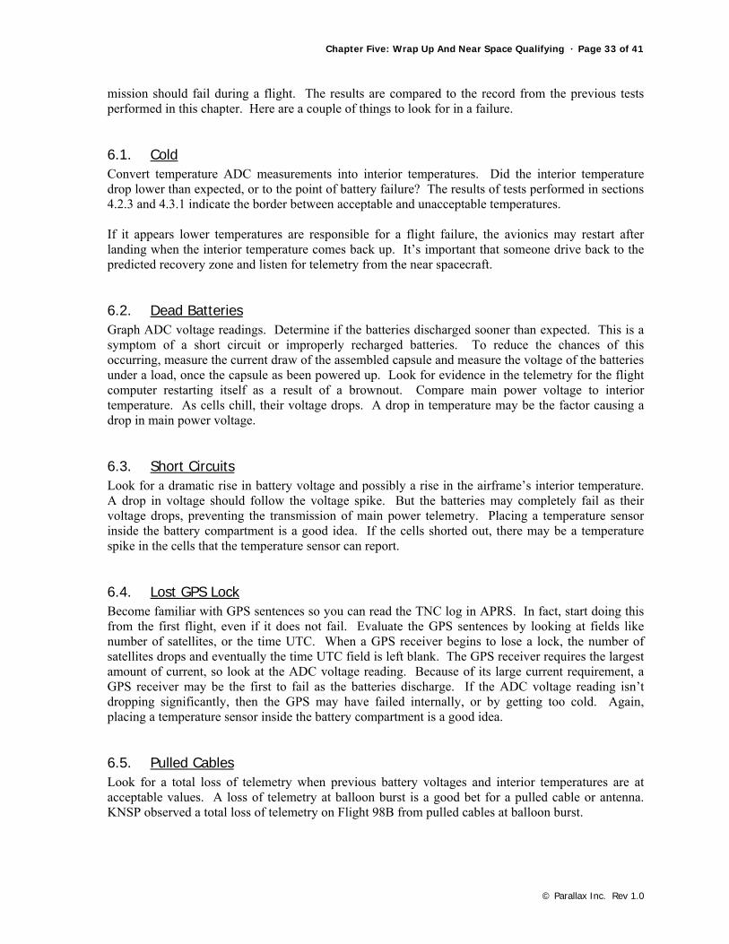
6.7. When Things Go Wrong, a Checklist Here is a list of items to look for during a failure analysis:
• Did the flight computer reset itself? • Did the main voltage drop too low? • Did the main voltage abruptly rise? • Did the interior temperature drop too low? • Were the GPS sentences incomplete? • Was there an unusual loss of packets? • Did anyone hear malformed packets at the time they were lost? • Did the failure appear to occur right after burst?
Good to Know - The Flight of Explorer II (1935) During my summer vacation in 2001, I made a visit to the geology museum of the South Dakota School of Mines and Technology in Rapid City. While there, I discovered a model of a gondola called Explorer II. The two aeronauts in this gondola created a new altitude record back in 1935 and became national heroes as result. The flight was launched nearby, in a location called Strato Bowl. This piqued my interested, so I did more research, which led me to the book The Pre-Astronauts, by Craig Ryan, published by The Naval Institute Press. With a little research I discovered the location of Strato Bowl. I made plans to visit it during my next summer vacation (being a teacher has its benefits). During the summer of 2002, I took a trip to Kansas for the Great Plains Super Launch (GPSL 2002). On the way I made several stops for hiking and camping in Yellowstone and the Black Hills. While in the Black Hills, I put a visit to Strato Bowl on my list of things to do. Strato Bowl is located at the end of a canyon in the Black Hills of South Dakota where it forms a hollow on one side of a “box canyon”. A large flat ground forms the base and there are and steep walls on three sides. The fourth side is open toward the north. There is an observation spot to the east, up on the rim of this open canyon. In January 1934, The National Geographic Society and the Army Air Corp (predecessor to the USAF) announced plans to loft a laboratory into the stratosphere. It was planned to set the balloon altitude record. As a result of this announcement, the Soviets made an attempt to beat the Americans with their own high altitude balloon flight. Three aeronauts rode inside a sealed and pressurized gondola to a new altitude record, 72,178 feet. During descent, the Soviet aeronauts released too much gas from their balloon. One by one the cables attaching their gondola to the balloon popped loose. It’s very likely the aeronauts were not aware of the cables coming off the balloon. At an altitude of 1,500 feet above the ground, the last cable popped loose, letting the gondola plummet earthward were the aeronauts were killed upon impact. A recording barometer however did survive, indicating their record altitude.
Chapter Five: Wrap Up And Near Space Qualifying · Page 35 of 41
© Parallax Inc. Rev 1.0
With this disaster fresh in their minds, the National Geographic Society and the Army Air Corp began constructing a balloon for their mission into the stratosphere. The balloon was constructed from three acres of rubberized cotton sheets glued together with rubber cement. This large balloon was named Explorer and hydrogen was used as its lifting gas. The pressurized gondola in which the aeronauts would ride into the stratosphere was 8.5 feet in diameter and welded together from a material called Dow metal. It was painted white on top and black on the bottom for thermal control reasons. From the announcement of the launch to the actual launch took only seven months. The first flight of the Explorer balloon was named Explorer I. It carried three aeronauts well into the stratosphere to perform experiments on cosmic rays, measure ozone, take air samples, and determine if bacteria or spores exit in the stratosphere. Almost 250,000 cubic feet of hydrogen was used to fill the Explorer balloon. The launch occurred from the Strato Bowl at 6:45 AM on July 28, 1934. The crew maintained constant radio contact with the ground station, W10FX. The gondola transmitted on a frequency of 13.05 MHz and was identified as station W10XFH. At 60,000 feet, the balloon began ripping apart. At that altitude the air was too thin to support life. Since the aeronauts did not carry partial pressure suits, they were forced to remain inside the sealed gondola until it had descended to below 20,000 feet where they could safely open the gondola’s hatch. During the descent, the aeronauts used their radio to report to listeners across the US the current status of their emergency. By the time the gondola had descended to 20,000 feet, the Explorer balloon was severely ripping apart. Sheets of rubberized cotton fell off the balloon, turning it into more of a parachute than a balloon. The aeronauts finally opened the hatch, donned warm clothes and parachutes, and prepared to jump. At an altitude of 5,000 feet above a farm field outside of Holdrege, Nebraska, the hydrogen remaining inside what was left of the balloon exploded, letting the Explorer I gondola free fall to the ground. The first aeronaut out of the gondola at 3,000 feet above the ground was Captain Anderson. The last one out of the gondola at 500 feet above the ground was Major Kepner. His altitude of 500 feet was just high enough for his parachute to open and safely land him on the ground. There’s a famous painting on the cover of a National Geographic Magazine of the time showing one of the aeronauts caught in the hatch while a second aeronaut is stepping on him to help push him out.
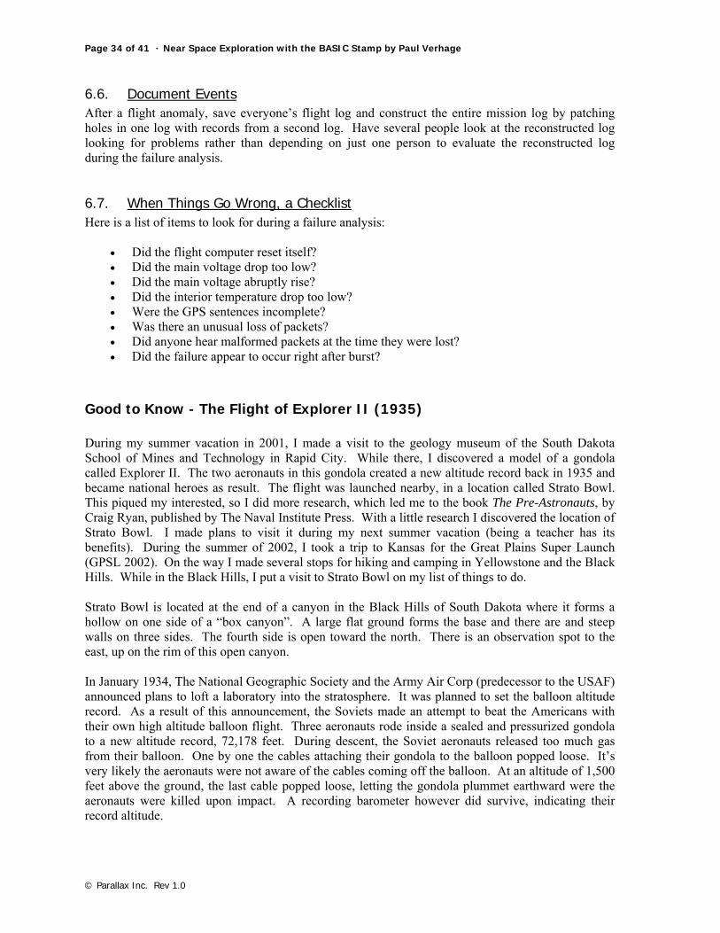
Escape Painting – In the back of the exhibit box.
The Explorer I crashed into a Nebraska cornfield and was crushed. The bail-out of the aeronauts and the impact of the gondola were recorded on film by aircraft. After all this, the Explorer I missed
Page 36 of 41 · Near Space Exploration with the BASIC Stamp by Paul Verhage
© Parallax Inc. Rev 1.0
making a new world altitude record by only 624 feet! The third aeronaut on the ill-fated flight of Explorer I was Captain Stevens. In 1924, Captain Stevens was the first person to take a photograph of the Moon’s shadow on Earth during an eclipse. He made this photograph from a balloon. It took another year to build a new balloon and gondola. The Explorer II balloon had a maximum volume of 3.7 million cubic feet, the largest balloon at that time. The combined weight of the balloon and gondola was nearly seven tons, about two tons less than the previous gondola and balloon. This time the balloon used helium gas for lift. 1685 tanks of helium were on hand at the Strato Bowl to fill the balloon. The first attempt to launch Explorer II ended on July 12, 1935, one hour before liftoff when the balloon collapsed, letting the helium escape. There was one other change. This time there were only two aeronauts in the gondola, Captain Orvil Anderson (Pilot) and Captain Albert Stevens (Commander, Scientific Observer, and Photographer). A crew of two was used on Explorer II for of two reasons: a crew of three was too cramped inside the gondola, and it appeared that a crew of three was bad luck. Filling the giant balloon with helium began the night before launch at 6:30 PM. A twenty-foot long panel in the balloon ripped during inflation, putting a hold in the filling. After making repairs to the balloon, filling restarted. The command “Up ship” was given and at 6:45 AM on November 11, 1935 as an estimated 21,000 people gathered on the rim to watch Explorer II lift off. Just after liftoff of the giant balloon, a downdraft threatened to push the balloon into the side of Strato Bowl. To prevent this, 75 pounds of fine lead shot was released from the gondola, increasing the ascent speed of Explorer II. The lead shot landed on the launch crew below and the gondola cleared the rim of Strato Bowl by fifty feet. At an altitude of 15,000 feet, Captain Anderson slowed the ascent of Explorer II so that instruments could be rigged and the ports sealed. Then the balloon began its ascent into the stratosphere at a rate of 400 feet per minute. Four hours after lift-off (about 10:55 AM), Captain Anderson slowed the balloon’s ascent to 200 feet per minute as the balloon reached its full volume. Explorer II had reached an altitude of 72,395 feet, the world’s record at that time. The aeronauts held their altitude for one hour and forty minutes. The aeronauts inside were the first humans to report seeing the earth’s curvature. A fan mounted to an arm mounted to the side of the gondola attempted to control the rotation and position of the gondola. However, the fan was ineffective in the stratosphere’s thin air. As a result, the Sun’s glare prevented the crew from making observations from all of the gondola’s view ports. Experiments on this flight included meteorological measurements of the stratosphere. The stratosphere’s electrical conductivity (ionization levels), air samples, cosmic ray measurements (researchers were trying to determine the direction rays entered the atmosphere), winds aloft, and effects of stratosphere and cosmic rays on molds were all observed and recorded. The first motion pictures taken in the stratosphere were made on this flight. Remember, at this time, the stratosphere was a great unknown. The crew of Explorer II maintained radio communications with the US, with Europe, where they gave a radio interview in London, and even with the pilot of an airplane flying over the Pacific Ocean. The air temperature inside the gondola dropped to –23 degrees F during the ascent, freezing food they brought along, like hard-boiled eggs. From the ground, people were able to watch the entire flight of Explorer II. At 12:30 PM, Explorer II began its descent. At an altitude of 1,000 feet, the aeronauts began tossing science instruments and air conditioning equipment out the gondola on their own parachutes. This protected equipment from a possible rough landing and kept chemicals in the air conditioning equipment from spilling and possibly harming the crew. Then they donned leather football helmets for additional protection. Explorer II landed at 3:10 PM in a prairie near the town White Lake, South
Chapter Five: Wrap Up And Near Space Qualifying · Page 37 of 41
© Parallax Inc. Rev 1.0
Dakota. The landing was so gentle that only a single bumper burst. Henry Ubel, a civilian, was the first person on the scene. He claimed the Explorer II landed like a feather and estimated the collapsed balloon covered one acre of ground. The entire flight had taken eight hours, thirteen minutes. The rubberized cotton envelope of Explorer II was cut into 1,000,000 bookmarks and given to members of the National Geographic Society. The outbreak of World War II prevented any more manned attempts for the next twenty years, until Project Strato-Lab and Man High were launched in the mid 1950’s. Visiting Sites Related To Explorer II Directions to the Strato Bowl If you wish to visit Strato Bowl and see more information on Explorer I and II, then you have to drive to the Black Hills of South Dakota. In this area I have found three places concerning Explorer I and II to visit. To get to Strato Bowl, follow these directions:
• Drive I-90 towards Rapid City. • Exit I-90 in Rapid City on Exit 57. • Go south on I-190. • I-190 ends on Route 44, also called Omaha Street. • Continue further south, two more blocks. • Make a left turn on Main Street. Note: Main Street is split into two roads of one-way traffic.
Take the road going to your left, or east. • Make the next right onto Mount Rushmore Road; you’re now going south. • Shortly afterwards, Mount Rushmore Road becomes Highway 16. • Eleven miles later is the town of Rockerville. Note: Highway 16 splits up and goes around
the town. • The two roads you want, Gondola Road and Strato Bowl Road, are located just before
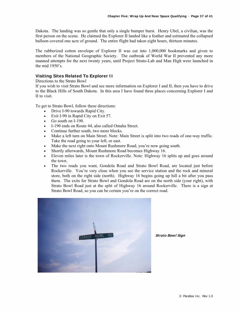
Rockerville. You’re very close when you see the service station and the rock and mineral store, both on the right side (north). Highway 16 begins going up hill a bit after you pass them. The exits for Strato Bowl and Gondola Road are on the north side (your right), with Strato Bowl Road just at the split of Highway 16 around Rockerville. There is a sign at Strato Bowl Road, so you can be certain you’re on the correct road.
Strato Bowl Sign

Page 38 of 41 · Near Space Exploration with the BASIC Stamp by Paul Verhage
© Parallax Inc. Rev 1.0
On to Strato Bowl Proper The Strato Bowl is located at the end of Strato Bowl Road, at GPS coordinates 43.97705 degrees north and 103.34658 degrees west. The road is winding and has plenty of trees on both sides. The road ends at a private drive and is surrounded with private homes. When I got there, I thought the gate was barring the rest of the way to Strato Bowl, so I didn’t try to get to the site. However, I did notice an area on my right, a very flat and open field with trimmed grass. So I drove back to Highway 16 in hopes of going to the Strato Bowl Observation Point.
Strato Bowl – Flat and open field.
To The Strato Bowl Viewing Area Go back to Highway 16 and drive away from Rockerville. About ½ mile away from Strato Bowl Road is the next exit, Gondola Road. The sign is on your right; there is no street sign for Gondola Road on the eastbound lane of Highway 16. Again, you want to go north on Gondola Road. The road ends in closed gate; there is enough room to park several cars off Highway 16. From here you hike the trail to the Observation Point. The hike is a very nice walk, about ½ mile long. Near the end the trail forks; take the left fork in the trail. As you approach the end of the trail you will see the guardrail and plaque of the Observation Point. From there you can look down into Strato Bowl.
Plaque – "From the floor of the Stratobowl below on November 11, 1935, The Stratoshere Balloon Explorer II rose to the world altitude record of 72,395 feet. The ascent was a made for scientific research under the joint auspices of the U.S. Army Air Corps and the National Geographic Society. Captain Albert W. Stevens, Air Corps commander and scientific observer. Captain Orvil A. Anderson, Air Corps Pilot."
Chapter Five: Wrap Up And Near Space Qualifying · Page 39 of 41
© Parallax Inc. Rev 1.0
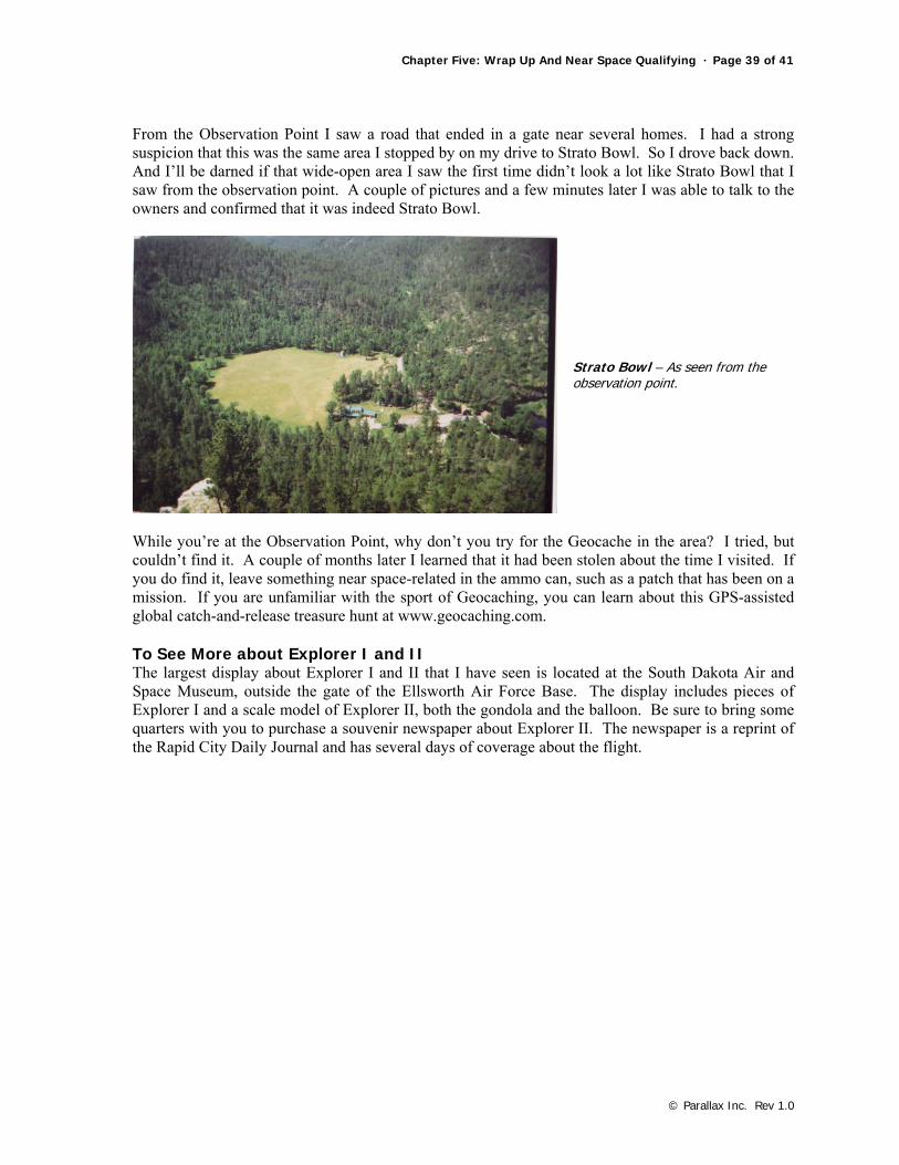
From the Observation Point I saw a road that ended in a gate near several homes. I had a strong suspicion that this was the same area I stopped by on my drive to Strato Bowl. So I drove back down. And I’ll be darned if that wide-open area I saw the first time didn’t look a lot like Strato Bowl that I saw from the observation point. A couple of pictures and a few minutes later I was able to talk to the owners and confirmed that it was indeed Strato Bowl.
Strato Bowl – As seen from the observation point.
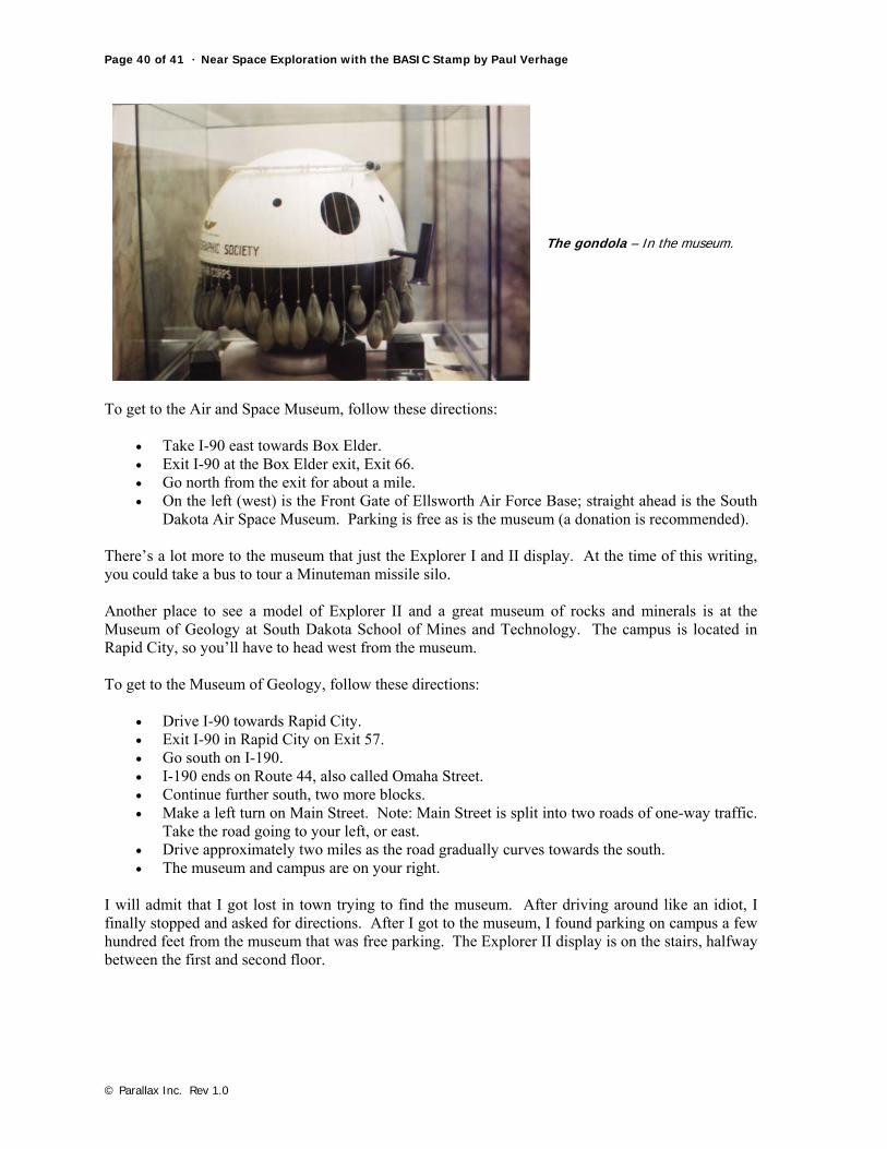
While you’re at the Observation Point, why don’t you try for the Geocache in the area? I tried, but couldn’t find it. A couple of months later I learned that it had been stolen about the time I visited. If you do find it, leave something near space-related in the ammo can, such as a patch that has been on a mission. If you are unfamiliar with the sport of Geocaching, you can learn about this GPS-assisted global catch-and-release treasure hunt at www.geocaching.com. To See More about Explorer I and II The largest display about Explorer I and II that I have seen is located at the South Dakota Air and Space Museum, outside the gate of the Ellsworth Air Force Base. The display includes pieces of Explorer I and a scale model of Explorer II, both the gondola and the balloon. Be sure to bring some quarters with you to purchase a souvenir newspaper about Explorer II. The newspaper is a reprint of the Rapid City Daily Journal and has several days of coverage about the flight.
Page 40 of 41 · Near Space Exploration with the BASIC Stamp by Paul Verhage
© Parallax Inc. Rev 1.0
The gondola – In the museum.
To get to the Air and Space Museum, follow these directions:
• Take I-90 east towards Box Elder. • Exit I-90 at the Box Elder exit, Exit 66. • Go north from the exit for about a mile. • On the left (west) is the Front Gate of Ellsworth Air Force Base; straight ahead is the South
Dakota Air Space Museum. Parking is free as is the museum (a donation is recommended). There’s a lot more to the museum that just the Explorer I and II display. At the time of this writing, you could take a bus to tour a Minuteman missile silo. Another place to see a model of Explorer II and a great museum of rocks and minerals is at the Museum of Geology at South Dakota School of Mines and Technology. The campus is located in Rapid City, so you’ll have to head west from the museum. To get to the Museum of Geology, follow these directions:
• Drive I-90 towards Rapid City. • Exit I-90 in Rapid City on Exit 57. • Go south on I-190. • I-190 ends on Route 44, also called Omaha Street. • Continue further south, two more blocks. • Make a left turn on Main Street. Note: Main Street is split into two roads of one-way traffic.
Take the road going to your left, or east. • Drive approximately two miles as the road gradually curves towards the south. • The museum and campus are on your right.
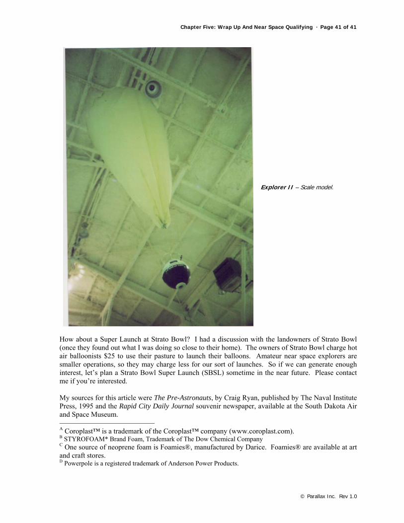
I will admit that I got lost in town trying to find the museum. After driving around like an idiot, I finally stopped and asked for directions. After I got to the museum, I found parking on campus a few hundred feet from the museum that was free parking. The Explorer II display is on the stairs, halfway between the first and second floor.
Chapter Five: Wrap Up And Near Space Qualifying · Page 41 of 41
© Parallax Inc. Rev 1.0
Explorer II – Scale model.
How about a Super Launch at Strato Bowl? I had a discussion with the landowners of Strato Bowl (once they found out what I was doing so close to their home). The owners of Strato Bowl charge hot air balloonists $25 to use their pasture to launch their balloons. Amateur near space explorers are smaller operations, so they may charge less for our sort of launches. So if we can generate enough interest, let’s plan a Strato Bowl Super Launch (SBSL) sometime in the near future. Please contact me if you’re interested. My sources for this article were The Pre-Astronauts, by Craig Ryan, published by The Naval Institute Press, 1995 and the Rapid City Daily Journal souvenir newspaper, available at the South Dakota Air and Space Museum. A Coroplast™ is a trademark of the Coroplast™ company (www.coroplast.com). B STYROFOAM* Brand Foam, Trademark of The Dow Chemical Company C One source of neoprene foam is Foamies®, manufactured by Darice. Foamies® are available at art and craft stores. D Powerpole is a registered trademark of Anderson Power Products.