Embed Size (px)
Citation preview

Chapter 9Chapter 9Capacitors

Basics of a Capacitor
• In its simplest form, a capacitor is an electrical
device constructed of two parallel plates separated
by an insulating material called the dielectric
• In the neutral state, both plates have an equal • In the neutral state, both plates have an equal
number of free electrons
• When a voltage source is connected to the
capacitor, electrons are removed from one plate and
an equal number are deposited on the other plate
• No electrons flow through the dielectric (insulator)

FIGURE 9-1 The basic capacitor.
Thomas L. Floyd
Electronics Fundamentals, 6e
Electric Circuit Fundamentals, 6e
Copyright ©2004 by Pearson Education, Inc.
Upper Saddle River, New Jersey 07458
All rights reserved.
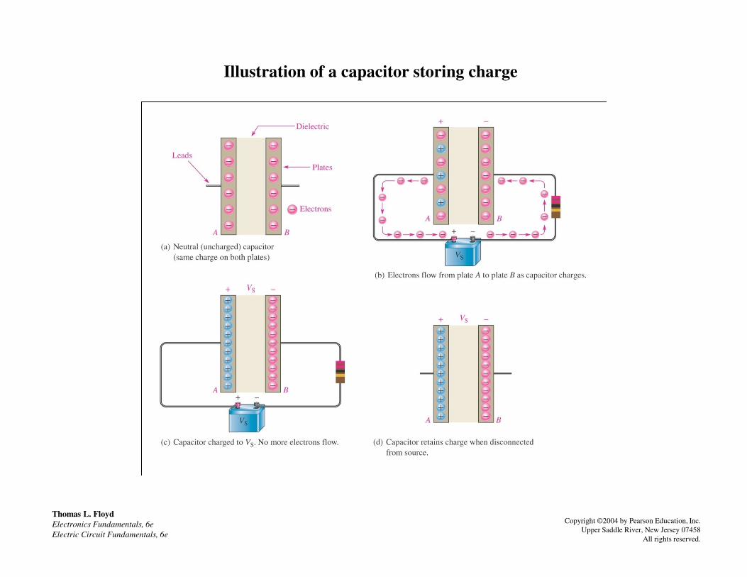
Illustration of a capacitor storing charge
Thomas L. Floyd
Electronics Fundamentals, 6e
Electric Circuit Fundamentals, 6e
Copyright ©2004 by Pearson Education, Inc.
Upper Saddle River, New Jersey 07458
All rights reserved.

Equivalent circuit for a no ideal capacitor
Thomas L. Floyd
Electronics Fundamentals, 6e
Electric Circuit Fundamentals, 6e
Copyright ©2004 by Pearson Education, Inc.
Upper Saddle River, New Jersey 07458
All rights reserved.
No Current flows through a capacitor except for undesired leakage current.

How a Capacitor Stores Energy
• A capacitor stores energy in the form of an
electric field that is established by the opposite
charges on the two plates
• A capacitor obeys Coulomb’s law:• A capacitor obeys Coulomb’s law:
A force exists between two point-source charges
that is directly proportional to the product of the
two charges and inversely proportional to the
square of the distance between the charges

The electric field stores energy in a capacitor. The beige area indicates the dielectric.
Thomas L. Floyd
Electronics Fundamentals, 6e
Electric Circuit Fundamentals, 6e
Copyright ©2004 by Pearson Education, Inc.
Upper Saddle River, New Jersey 07458
All rights reserved.

Lines of force are created by opposite charges
Thomas L. Floyd
Electronics Fundamentals, 6e
Electric Circuit Fundamentals, 6e
Copyright ©2004 by Pearson Education, Inc.
Upper Saddle River, New Jersey 07458
All rights reserved.
The unit for Capacitance is the Farad (F)
1 Farad = 1 Coloumb/1V
Usually specified un Micro-Farads (uF)

Characteristics of a Capacitor
• Capacitance is directly proportional to the physical size of the plates as determined by the plate area
• Capacitance is inversely proportional to the distance between the plates
• The measure of the dielectric material’s ability to establish • The measure of the dielectric material’s ability to establish an electric field is called the dielectric constant. Capacitance is directly proportional to the dielectric constant
• The measure of how much voltage a capacitor can handle across it’s plates is called dielectric strength or breakdown voltage. All capacitors specify a safe voltage at which to operate the capacitor.
• Most capacitors have a very thin dielectric and a very large plate area (often stacked or rolled up).

Capacitance is directly proportional to plate area (A)
Thomas L. Floyd
Electronics Fundamentals, 6e
Electric Circuit Fundamentals, 6e
Copyright ©2004 by Pearson Education, Inc.
Upper Saddle River, New Jersey 07458
All rights reserved.
Less plate area = Less Capacitance
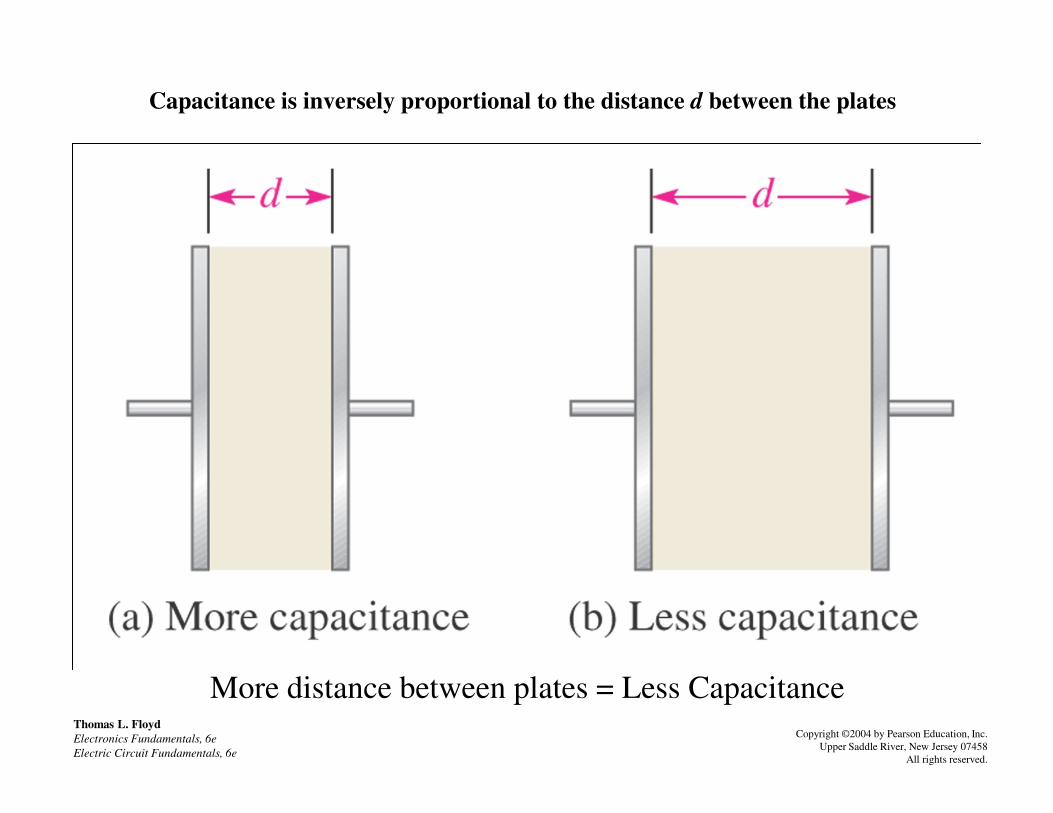
Capacitance is inversely proportional to the distance d between the plates
Thomas L. Floyd
Electronics Fundamentals, 6e
Electric Circuit Fundamentals, 6e
Copyright ©2004 by Pearson Education, Inc.
Upper Saddle River, New Jersey 07458
All rights reserved.
More distance between plates = Less Capacitance

Charging a capacitor
Thomas L. Floyd
Electronics Fundamentals, 6e
Electric Circuit Fundamentals, 6e
Copyright ©2004 by Pearson Education, Inc.
Upper Saddle River, New Jersey 07458
All rights reserved.
Uncharged Cap
Appears as a short
the instant the switch
is closed
Charging Cap
Current drops and
voltage across cap
rises
Charged Cap
Appears as an open
All current stops and
VC = VS
No current except for
leakage current and
capacitor stores the
charge

Discharging a Capacitor
Thomas L. Floyd
Electronics Fundamentals, 6e
Electric Circuit Fundamentals, 6e
Copyright ©2004 by Pearson Education, Inc.
Upper Saddle River, New Jersey 07458
All rights reserved.
Current reverses:
High at first then
drops as voltage
drops
Back to where it
started
•This phenomenon often makes it appear that current is passing through the cap
•It does not
•The reversing current goes back to the supply

Fixed Capacitors
• Stacked-foil mica capacitors are made of alternate layers of metal foil and thin
sheets of mica
• Silver mica are formed by stacking mica sheets with silver electrode material
screened on them
• Range from 1pF to 0.1 uF @ 2500V• Range from 1pF to 0.1 uF @ 2500V
Low Capacitance @ High Voltage

Fixed Capacitors
• Ceramic capacitors provide very high dielectric
constants, and relatively large capacitance in a
small physical size
• Capacitance ranges are from 1pF to 2.2µF @ • Capacitance ranges are from 1pF to 2.2µF @
2500V
Medium Capacitance @ High Voltage
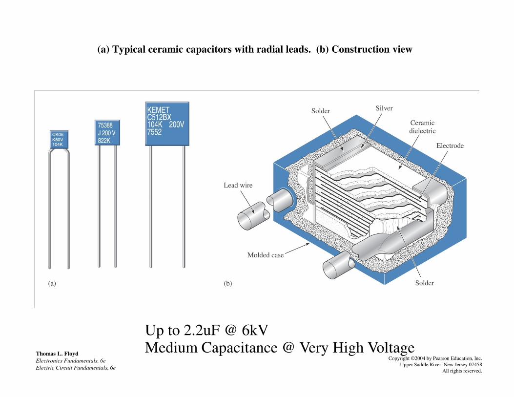
(a) Typical ceramic capacitors with radial leads. (b) Construction view
Thomas L. Floyd
Electronics Fundamentals, 6e
Electric Circuit Fundamentals, 6e
Copyright ©2004 by Pearson Education, Inc.
Upper Saddle River, New Jersey 07458
All rights reserved.
Up to 2.2uF @ 6kVMedium Capacitance @ Very High Voltage

Electrolytic Capacitors
• Two common types of electrolytic
capacitors are Aluminum and Tantalum
electrolyticselectrolytics
• Safety Warning: The voltage polarity of
these devices must be observed, as reversal
of polarity will usually result in complete
destruction of the capacitor

Electrolytic Capacitors
• Electrolytic capacitors have higher capacitance but
lower voltage ratings and higher leakage current
• They come in capacitance values from 1µF to
200,000 µF, with voltage ratings to 350 V200,000 µF, with voltage ratings to 350 V
High Capacitance @ Low (Polarized) Voltage

Basic construction of axial-lead tubular plastic-film dielectric capacitor.
Thomas L. Floyd
Electronics Fundamentals, 6e
Electric Circuit Fundamentals, 6e
Copyright ©2004 by Pearson Education, Inc.
Upper Saddle River, New Jersey 07458
All rights reserved.
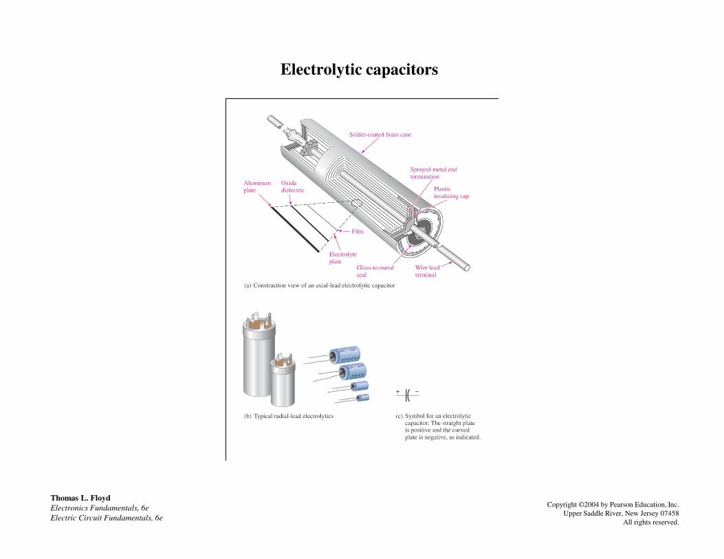
Electrolytic capacitors
Thomas L. Floyd
Electronics Fundamentals, 6e
Electric Circuit Fundamentals, 6e
Copyright ©2004 by Pearson Education, Inc.
Upper Saddle River, New Jersey 07458
All rights reserved.

Construction view of a typical “tear drop” shaped tantalum electrolytic capacitor
Thomas L. Floyd
Electronics Fundamentals, 6e
Electric Circuit Fundamentals, 6e
Copyright ©2004 by Pearson Education, Inc.
Upper Saddle River, New Jersey 07458
All rights reserved.
“Tear Drop” shaped tantalum electrolytic capacitor.
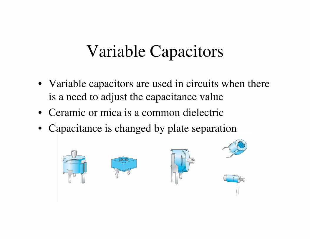
Variable Capacitors
• Variable capacitors are used in circuits when there
is a need to adjust the capacitance value
• Ceramic or mica is a common dielectric
• Capacitance is changed by plate separation

FIGURE 9-16 Schematic symbol for a variable capacitor.
Thomas L. Floyd
Electronics Fundamentals, 6e
Electric Circuit Fundamentals, 6e
Copyright ©2004 by Pearson Education, Inc.
Upper Saddle River, New Jersey 07458
All rights reserved.
Schematic symbol for a variable capacitor.

Variable Air Capacitor
•Air Capacitors are used in high frequency (RF)
applications
•The space between the plates (air) is the dielectric
•This is an example of a variable air capacitor probably
used in a radio tuner

Series Capacitors
• When capacitors are connected in series, the total capacitance is less than the smallest capacitance value
• This is because the effective plate separation increases
11
1/C1 + 1/C2 + 1/C3 + … + 1/Cn

Capacitors in series produce a total capacitance that is less than the smallest value
Thomas L. Floyd
Electronics Fundamentals, 6e
Electric Circuit Fundamentals, 6e
Copyright ©2004 by Pearson Education, Inc.
Upper Saddle River, New Jersey 07458
All rights reserved.
CT = 76.7pF

Thomas L. Floyd
Electronics Fundamentals, 6e
Electric Circuit Fundamentals, 6e
Copyright ©2004 by Pearson Education, Inc.
Upper Saddle River, New Jersey 07458
All rights reserved.
•In a DC Circuit, current stops flowing when the smallest cap is charged
•Vs = VC1 + VC2

FIGURE 9-22 P 406
Capacitor Voltages – The smallest cap holds the largest voltage
And versa visa (The smallest cap charges first halting all current flow)
Thomas L. Floyd
Electronics Fundamentals, 6e
Electric Circuit Fundamentals, 6e
Copyright ©2004 by Pearson Education, Inc.
Upper Saddle River, New Jersey 07458
All rights reserved.
V x = (CT/Cx)VS

Parallel Capacitors
• The total parallel capacitance is the sum of all
capacitors in parallel
CT = C1 + C2 + C3 + … + Cn
• This is because the effective plate area increases
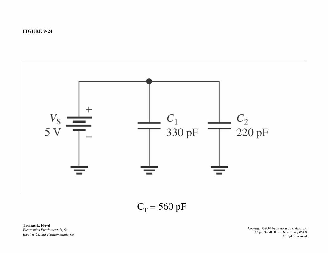
FIGURE 9-24
Thomas L. Floyd
Electronics Fundamentals, 6e
Electric Circuit Fundamentals, 6e
Copyright ©2004 by Pearson Education, Inc.
Upper Saddle River, New Jersey 07458
All rights reserved.
CT = 560 pF

FIGURE 9-26
Thomas L. Floyd
Electronics Fundamentals, 6e
Electric Circuit Fundamentals, 6e
Copyright ©2004 by Pearson Education, Inc.
Upper Saddle River, New Jersey 07458
All rights reserved.
CT = .133uF
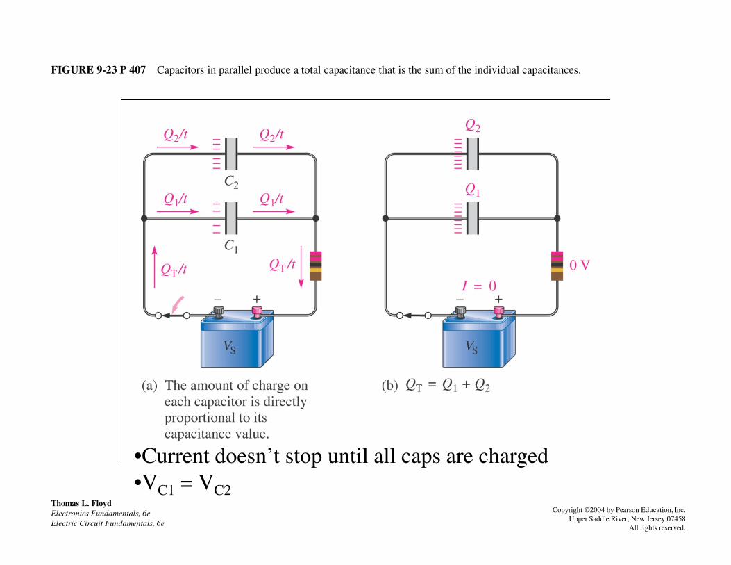
FIGURE 9-23 P 407 Capacitors in parallel produce a total capacitance that is the sum of the individual capacitances.
Thomas L. Floyd
Electronics Fundamentals, 6e
Electric Circuit Fundamentals, 6e
Copyright ©2004 by Pearson Education, Inc.
Upper Saddle River, New Jersey 07458
All rights reserved.
•Current doesn’t stop until all caps are charged
•VC1 = VC2
RC Time Constant
• The voltage across a capacitor cannot
change instantaneously because a finite time
is required to move charge from one point is required to move charge from one point
to another (limited by circuit resistance)
• The time constant of a series RC circuit is a
time interval that equals the product of the
resistance and the capacitance
ττττ = RC

Current and voltage in a charging and discharging capacitor
Thomas L. Floyd
Electronics Fundamentals, 6e
Electric Circuit Fundamentals, 6e
Copyright ©2004 by Pearson Education, Inc.
Upper Saddle River, New Jersey 07458
All rights reserved.

Charging and Discharging• The charging curve is an increasing exponential
• The discharging curve is a decreasing exponential
• It takes 5 time constants to change the voltage by
99% (charging or discharging), this is called the
transient timetransient time

Charge and discharge curves shown together
Charge v
Charge i
Discharge v & i
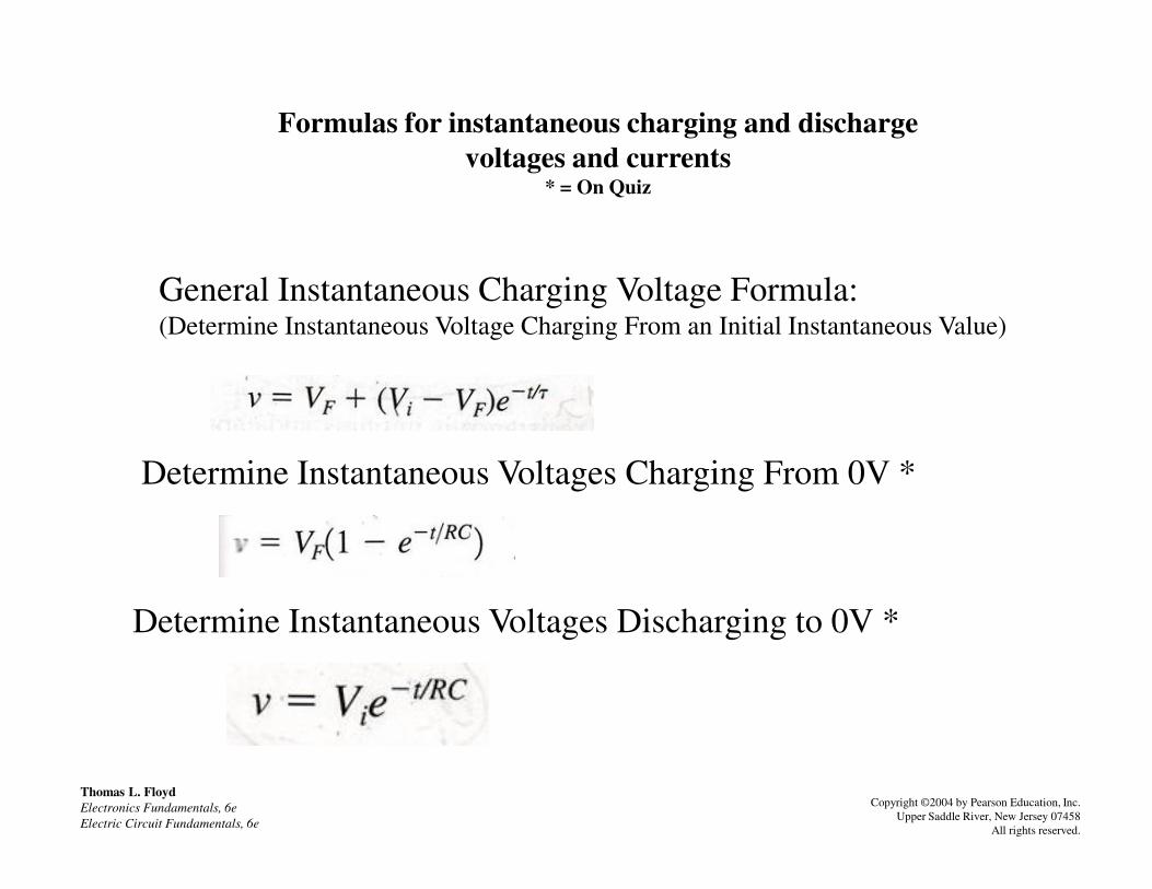
Formulas for instantaneous charging and discharge
voltages and currents* = On Quiz
General Instantaneous Charging Voltage Formula:(Determine Instantaneous Voltage Charging From an Initial Instantaneous Value)
Thomas L. Floyd
Electronics Fundamentals, 6e
Electric Circuit Fundamentals, 6e
Copyright ©2004 by Pearson Education, Inc.
Upper Saddle River, New Jersey 07458
All rights reserved.
Determine Instantaneous Voltages Charging From 0V *
Determine Instantaneous Voltages Discharging to 0V *
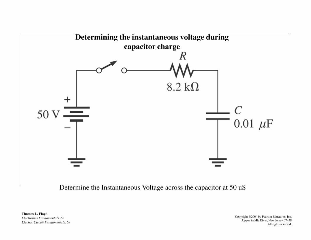
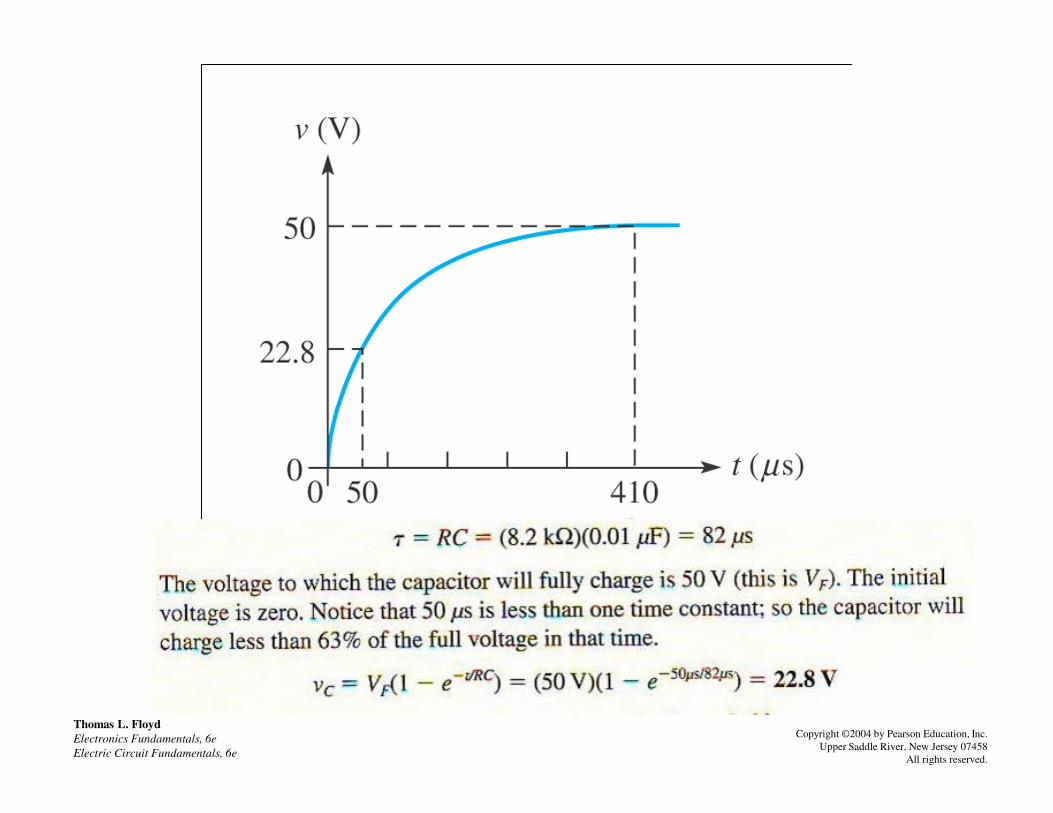
Determining the instantaneous voltage during
capacitor charge
Thomas L. Floyd
Electronics Fundamentals, 6e
Electric Circuit Fundamentals, 6e
Copyright ©2004 by Pearson Education, Inc.
Upper Saddle River, New Jersey 07458
All rights reserved.
Determine the Instantaneous Voltage across the capacitor at 50 uS
Thomas L. Floyd
Electronics Fundamentals, 6e
Electric Circuit Fundamentals, 6e
Copyright ©2004 by Pearson Education, Inc.
Upper Saddle River, New Jersey 07458
All rights reserved.

Determining the instantaneous voltage during capacitor
discharge
Thomas L. Floyd
Electronics Fundamentals, 6e
Electric Circuit Fundamentals, 6e
Copyright ©2004 by Pearson Education, Inc.
Upper Saddle River, New Jersey 07458
All rights reserved.
Determine the capacitor voltage 6 ms after the switch is closed
The capacitor is charged

Thomas L. Floyd
Electronics Fundamentals, 6e
Electric Circuit Fundamentals, 6e
Copyright ©2004 by Pearson Education, Inc.
Upper Saddle River, New Jersey 07458
All rights reserved.

Capacitive Reactance, XC
• Capacitive reactance (XC) is the opposition to
sinusoidal current, expressed in ohms
• The rate of change of voltage is directly related to
frequencyfrequency
• As the frequency increases, the rate of change of
voltage increases, and thus current ( i ) increases
• An increase in i means that there is less opposition
to current (XC is less)
• XC is inversely proportional to i and to frequency

The current in a capacitive circuit varies directly with the frequency of the source
voltage
Thomas L. Floyd
Electronics Fundamentals, 6e
Electric Circuit Fundamentals, 6e
Copyright ©2004 by Pearson Education, Inc.
Upper Saddle River, New Jersey 07458
All rights reserved.
Because the voltage rate of change is higher at higher frequencies,
the capacitive current increases proportionately with the frequency
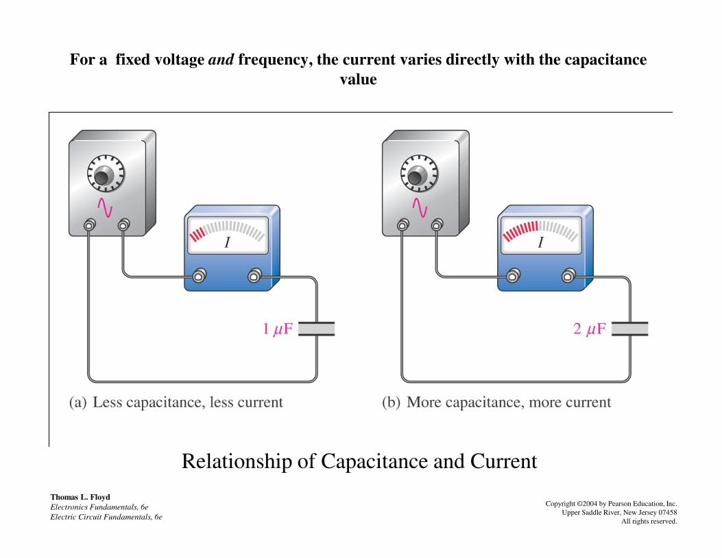
For a fixed voltage and frequency, the current varies directly with the capacitance
value
Thomas L. Floyd
Electronics Fundamentals, 6e
Electric Circuit Fundamentals, 6e
Copyright ©2004 by Pearson Education, Inc.
Upper Saddle River, New Jersey 07458
All rights reserved.
Relationship of Capacitance and Current

Formula for X
Rate of change of a sine wave increases when frequency increases
Thomas L. Floyd
Electronics Fundamentals, 6e
Electric Circuit Fundamentals, 6e
Copyright ©2004 by Pearson Education, Inc.
Upper Saddle River, New Jersey 07458
All rights reserved.
Formula for XC

FIGURE 9-41 P 418
Determine XC in the circuit below
1 kHz
Thomas L. Floyd
Electronics Fundamentals, 6e
Electric Circuit Fundamentals, 6e
Copyright ©2004 by Pearson Education, Inc.
Upper Saddle River, New Jersey 07458
All rights reserved.
1 kHz

Ohm’s Law for Capacitors
Vrms = I XC
Irms = Vrms/Xc
Xc = VrmsI
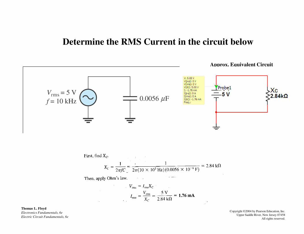
Determine the RMS Current in the circuit below
Approx. Equivalent Circuit
Thomas L. Floyd
Electronics Fundamentals, 6e
Electric Circuit Fundamentals, 6e
Copyright ©2004 by Pearson Education, Inc.
Upper Saddle River, New Jersey 07458
All rights reserved.

Capacitors in ac Circuits
• When a sine wave signal is applied to a capacitor,
the instantaneous capacitor current is equal to the
capacitance times the instantaneous rate of change
of the voltage across the capacitor of the voltage across the capacitor
• This rate of change is a maximum positive when
the rising sine wave crosses zero
• This rate of change is a maximum negative when
the falling sine wave crosses zero
• The rate of change is zero at the maximum and
minimum of the sine wave

The rates of change of a sine wave
Thomas L. Floyd
Electronics Fundamentals, 6e
Electric Circuit Fundamentals, 6e
Copyright ©2004 by Pearson Education, Inc.
Upper Saddle River, New Jersey 07458
All rights reserved.
The higher the rate of voltage change, the higher the capacitor current

Analysis of Capacitive ac Circuit
• The current leads the voltage by 90° in a purely capacitive ac circuit (ICE)
• This is because:
– Current in a capacitor is dependent upon the rate of voltage change
– The highest rate of change in voltage is when it crosses zero
VC ≈ VS
voltage is when it crosses zero volts.
• This is also when the capacitor is closer to being discharged and easily accepts higher current change.
– The least rate of change in voltage is near the peak voltage
– There is zero rate of change in voltage at peak.
• This is also when the capacitor is closest to being charged and doesn’t easily accept much current change.
Close
to
Charged
Close
to
Discharged
Close
to
Charged
Close
to
Discharged
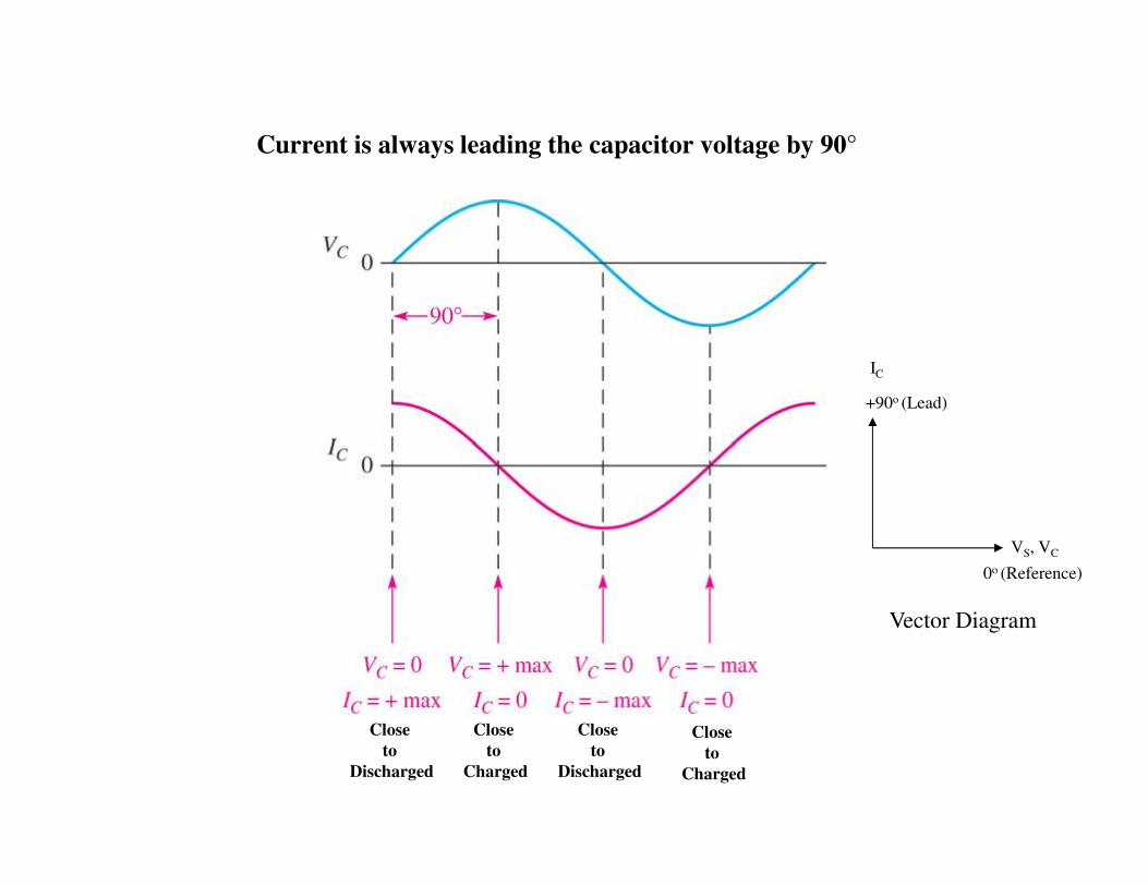
Current is always leading the capacitor voltage by 90°
IC
+90o (Lead)
VS, VC
0o (Reference)
Vector Diagram
Close
to
Charged
Close
to
Discharged
Close
to
Charged
Close
to
Discharged
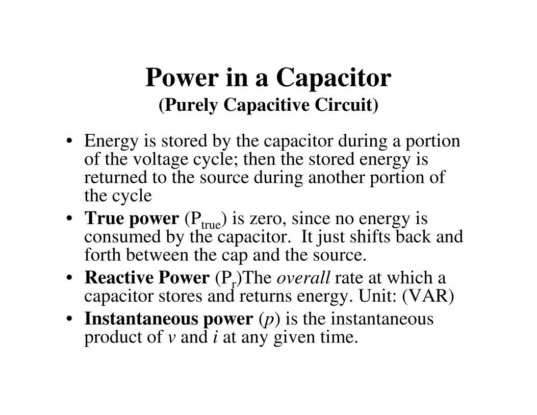
Power in a Capacitor(Purely Capacitive Circuit)
• Energy is stored by the capacitor during a portion of the voltage cycle; then the stored energy is returned to the source during another portion of the cycle
• True power (P ) is zero, since no energy is • True power (Ptrue) is zero, since no energy is consumed by the capacitor. It just shifts back and forth between the cap and the source.
• Reactive Power (Pr)The overall rate at which a capacitor stores and returns energy. Unit: (VAR)
• Instantaneous power (p) is the instantaneous product of v and i at any given time.
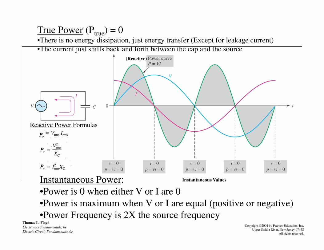
FIGURE 9-45 Power curve for a capacitor.
Reactive Power Formulas
True Power (Ptrue) = 0•There is no energy dissipation, just energy transfer (Except for leakage current)
•The current just shifts back and forth between the cap and the source
(Reactive)
Thomas L. Floyd
Electronics Fundamentals, 6e
Electric Circuit Fundamentals, 6e
Copyright ©2004 by Pearson Education, Inc.
Upper Saddle River, New Jersey 07458
All rights reserved.
Instantaneous Power:
•Power is 0 when either V or I are 0
•Power is maximum when V or I are equal (positive or negative)
•Power Frequency is 2X the source frequency
Reactive Power Formulas
Instantaneous Values

FIGURE 9-46Determine the true power and reactive power for the circuit below
Thomas L. Floyd
Electronics Fundamentals, 6e
Electric Circuit Fundamentals, 6e
Copyright ©2004 by Pearson Education, Inc.
Upper Saddle River, New Jersey 07458
All rights reserved.
Ptrue = 0
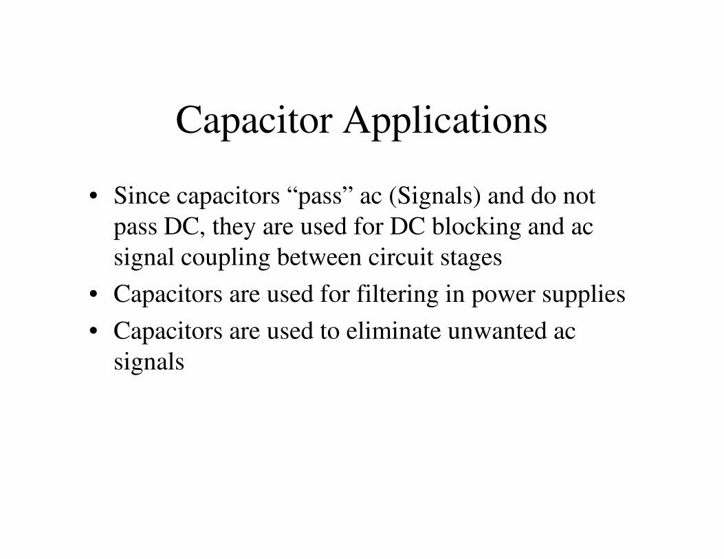
Capacitor Applications
• Since capacitors “pass” ac (Signals) and do not
pass DC, they are used for DC blocking and ac
signal coupling between circuit stages
• Capacitors are used for filtering in power supplies• Capacitors are used for filtering in power supplies
• Capacitors are used to eliminate unwanted ac
signals

An application of a capacitor used to block DC and couple ac in an amplifier
Thomas L. Floyd
Electronics Fundamentals, 6e
Electric Circuit Fundamentals, 6e
Copyright ©2004 by Pearson Education, Inc.
Upper Saddle River, New Jersey 07458
All rights reserved.
Capacitors “Pass AC and Block DC”
(Pass Signals/Changing Current and Block DC)
Biased SignalUn-Biased Signal

FIGURE 9-55 Capacitively coupled amplifier.
Thomas L. Floyd
Electronics Fundamentals, 6e
Electric Circuit Fundamentals, 6e
Copyright ©2004 by Pearson Education, Inc.
Upper Saddle River, New Jersey 07458
All rights reserved.
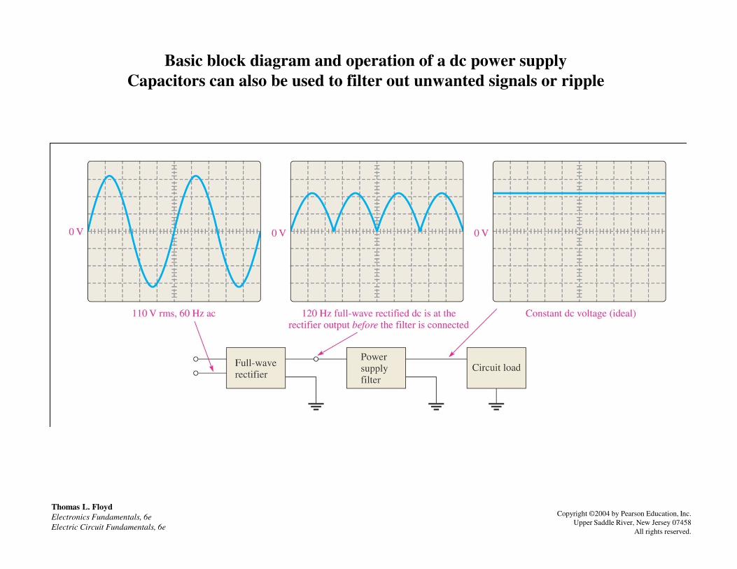
Basic block diagram and operation of a dc power supply
Capacitors can also be used to filter out unwanted signals or ripple
Thomas L. Floyd
Electronics Fundamentals, 6e
Electric Circuit Fundamentals, 6e
Copyright ©2004 by Pearson Education, Inc.
Upper Saddle River, New Jersey 07458
All rights reserved.
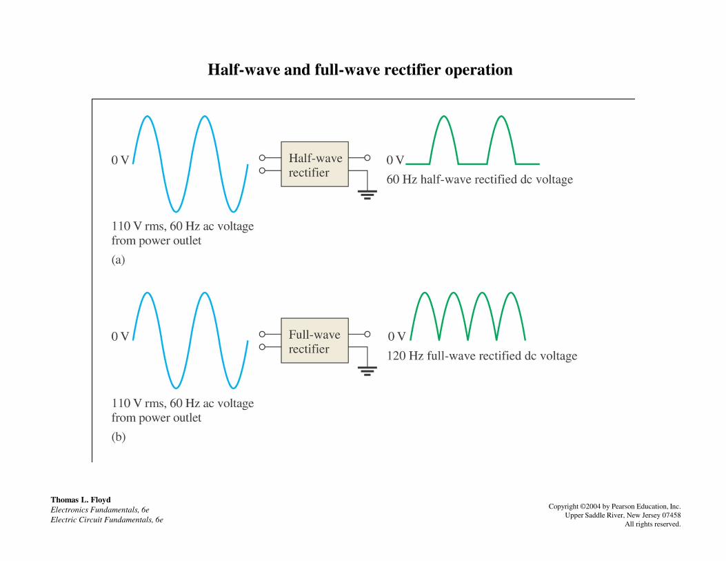
Half-wave and full-wave rectifier operation
Thomas L. Floyd
Electronics Fundamentals, 6e
Electric Circuit Fundamentals, 6e
Copyright ©2004 by Pearson Education, Inc.
Upper Saddle River, New Jersey 07458
All rights reserved.

Basic operation of a power supply filter capacitor
Thomas L. Floyd
Electronics Fundamentals, 6e
Electric Circuit Fundamentals, 6e
Copyright ©2004 by Pearson Education, Inc.
Upper Saddle River, New Jersey 07458
All rights reserved.
The capacitance of the filter capacitor(s) is usually fairly large

Example of the operation of a bypass capacitor
Thomas L. Floyd
Electronics Fundamentals, 6e
Electric Circuit Fundamentals, 6e
Copyright ©2004 by Pearson Education, Inc.
Upper Saddle River, New Jersey 07458
All rights reserved.
Unwanted Signal is “Passed” or”Shunted” to ground
Input
Output

More Capacitor Applications
• Capacitors are used in filters, to select one ac signal
with a certain specified frequency from a wide
range of signals with many different frequencies
– For example, the selection of one radio station and – For example, the selection of one radio station and
rejecting the others (High/Low/Bandpass Filters)
• Capacitors are used in timing circuits to generate
time delays, based on the RC time constant
• Dynamic memories used in computers are simply
very tiny capacitors used as a storage element

Checking a capacitor with an analog ohmmeter. This check shows a good capacitor.
Thomas L. Floyd
Electronics Fundamentals, 6e
Electric Circuit Fundamentals, 6e
Copyright ©2004 by Pearson Education, Inc.
Upper Saddle River, New Jersey 07458
All rights reserved.
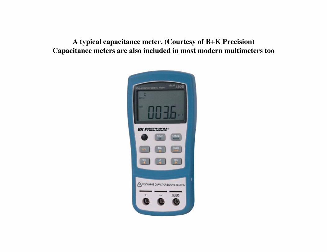
A typical capacitance meter. (Courtesy of B+K Precision)
Capacitance meters are also included in most modern multimeters too