Embed Size (px)
Citation preview

Bay Delta Conservation Plan/California WaterFix Final EIR/EIS
Administrative Final 9-1
2016 ICF 00139.14
Chapter 9 1
Geology and Seismicity 2
9.0 Summary Comparison of Alternatives 3
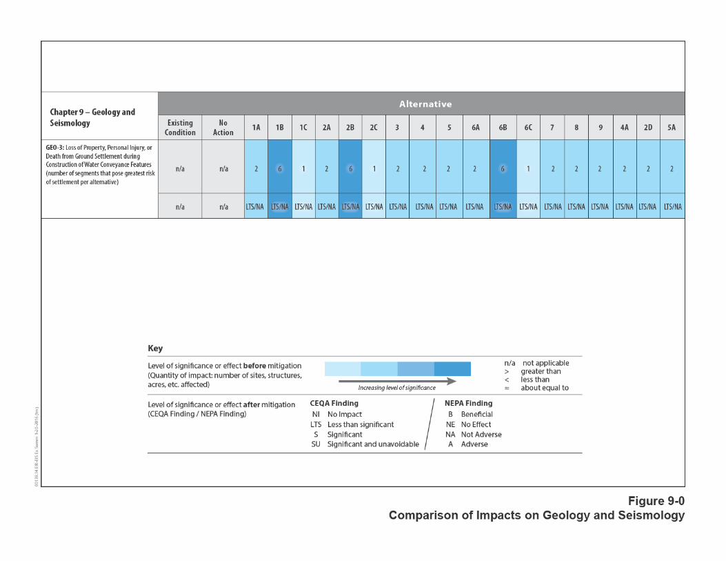
A summary comparison of important geologic impacts is provided in Figure 9-0. This figure provides 4 information on the magnitude of both adverse and beneficial geologic impacts that are expected to 5 result from implementation of the alternatives. Important impacts to consider include the loss of 6 property or likelihood of personal injury or death as a result of settlement caused by dewatering 7 during construction of water conveyance facilities. 8
Each alternative, with the exception of the No Action Alternative, would have conveyance segments 9 that pose a greater risk of settlement than do Existing Conditions. Six segments would be at risk 10 under Alternatives 1B, 2B, and 6B, whereas only one segment would be at risk under Alternatives 11 1C, 2C, and 6C. Alternative 4A would fall within this range, with two segments at risk. 12
Executive Summary Table ES-8 provides a summary of all impacts disclosed in this chapter. 13
9.1 Environmental Setting/Affected Environment 14
This section of Chapter 9 describes the existing geologic and seismologic conditions and the 15 associated potential geologic, seismic, and geotechnical hazards in the Sacramento–San Joaquin 16 Delta (Delta) and Suisun Marsh area (Figure 1-9 in Chapter 1, Introduction). The information 17 presented is based on existing information from published and unpublished sources. Specifically, the 18 regional and site information was compiled from maps and reports published by various agencies, 19 researchers, and consultants, including the California Department of Water Resources (DWR), 20 CALFED Bay-Delta Program (CALFED), U.S. Army Corps of Engineers (USACE), U.S. Geological Survey 21 (USGS), and California Geological Survey (CGS, formerly California Division of Mines and Geology). 22 This section describes the environmental setting for the following areas, each of which has the 23 potential to be affected by activities under the proposed project. 24
Geologic setting focuses on the subsurface soils and the underlying bedrock units, including 25 existing natural levee and channel deposits. Near-surface soils are fully discussed in Chapter 10, 26 Soils, which describes surface erosion, subsidence processes, and other soil hazards. Mineral 27 resources that could be affected by construction and operation of the action alternatives are 28 fully discussed in Chapter 26, Mineral Resources. 29
Seismologic setting describes historical seismic events and the ground shaking potential during 30 earthquakes. 31
Geologic and seismic hazards, including surface fault rupture, seismic-induced liquefaction, and 32 slope instability and ground failure, are identified. Potential levee instability and breaches 33 related to geologic processes that could result in flooding are also described. See Chapter 6, 34 Surface Water and Appendix 3E, Potential Seismic and Climate Change Risks to SWP/CVP Water 35 Supplies, for additional discussion of levee stability. 36
Geology and Seismicity
Bay Delta Conservation Plan/California WaterFix Final EIR/EIS
Administrative Final 9-2
2016 ICF 00139.14
Additionally, the federal and state regulatory settings for the identified geologic and seismic hazards 1 are presented with a listing of applicable design codes. 2
The setting information for geology and seismicity, except where otherwise noted, is derived from 3 the geology and seismicity appendix that was included in the conceptual engineering reports (CERs) 4 prepared for the BDCP/California WaterFix. 5
Conceptual Engineering Report—Isolated Conveyance Facility—All Tunnel Option (California 6 Department of Water Resources 2010a). 7
Conceptual Engineering Report—Isolated Conveyance Facility—Pipeline/Tunnel Option—8 Addendum (California Department of Water Resources 2010b). 9
Conceptual Engineering Report—Isolated Conveyance Facility—East Option (California 10 Department of Water Resources 2009a). 11
Conceptual Engineering Report—Isolated Conveyance Facility—East Option—Addendum 12 (California Department of Water Resources 2010c). 13
Conceptual Engineering Report—Isolated Conveyance Facility—West Option (California 14 Department of Water Resources 2009b). 15
Conceptual Engineering Report—Isolated Conveyance Facility—West Option—Addendum 16 (California Department of Water Resources 2010d). 17
Option Description Report—Separate Corridors Option (California Department of Water 18 Resources 2010e). 19
Conceptual Engineering Report—Dual Conveyance Facility Modified Pipeline/Tunnel Option—20 Clifton Court Forebay Pumping Plant (MPTO/CCO), Volume 1. (California Department of Water 21 Resources 2015). 22
9.1.1 Potential Environmental Effects Area 23
The Plan Area (the area covered by the proposed project) consists of the Delta and Suisun Marsh 24 which lie within California’s Central Valley, which is approximately 465 miles long and 40–60 miles 25 wide. The valley is bound by the Sierra Nevada on the east and the Coast Ranges on the west (Figure 26 9-1). Paleogeographic reconstructions of this region indicate that Miocene sedimentation was 27 similar to a modern fore-arc basin (a sea floor depression between a subduction zone and an 28 associated volcanic arc), shedding arkosic (granular quartz and feldspar or mica) and volcanoclastic 29 sediment westward from the continent. (Figure 9-2 presents a geologic time scale.) In the mid-30 Pliocene Epoch, a shift in plate tectonics triggered uplift of the Coast Ranges, which gradually closed 31 the southern marine outlet to the basin. By the late Pliocene, sub-aerial conditions prevailed 32 throughout the valley, resulting from marine regression (i.e., where shoreline shifts oceanward, 33 exposing formerly submerged areas) and sedimentation from the west. During Pleistocene Epoch, 34 the valley separated from the Pacific Ocean and developed internal drainage, the modern outlet 35 being the Carquinez Strait, through which the Sacramento River flows to the San Francisco Bay 36 (Lettis and Unruh 1991, pp. 164–176). 37
The historical Delta formed approximately 5,000 years ago at the inland margin of the San Francisco 38 Bay Estuary as two overlapping geomorphic units. The Sacramento River Delta comprises about 39 30% of the total area and was influenced by the interaction of rising sea level and river floods that 40 created channels, natural levees, and marsh plains. During large river flood events, silt and sand 41
Geology and Seismicity
Bay Delta Conservation Plan/California WaterFix Final EIR/EIS
Administrative Final 9-3
2016 ICF 00139.14
were deposited adjacent to the river channel, forming natural levees above the marsh plain. In 1 contrast, the larger San Joaquin River Delta, located in the central and southern portions of the Delta 2 and having relatively small flood flows and low sediment supply, formed as an extensive, levee free 3 freshwater tidal marsh dominated by tidal flows and organic soil (peat and muck) accretion 4 (Atwater and Belknap 1980). Because the San Joaquin River Delta had less well-defined levees, 5 sediment were deposited more uniformly across the floodplain during high water, creating an 6 extensive tule marsh with many small branching tributary channels. As a result of the different 7 amounts of inorganic sediment supply, the peat and muck of the San Joaquin River Delta grade 8 northward into peaty mud and then into mud as it approaches the natural levees and flood basins of 9 the Sacramento River Delta (Atwater and Belknap 1980). 10
9.1.1.1 Regional Geology 11
The Great Valley is a northwest-trending structural basin, separating the primarily granitic rock of 12 the Sierra Nevada from the primarily Franciscan Formation rock of the California Coastal Range 13 (Norris and Webb 1990). The basin is filled with an approximately 3- to 6-mile-thick layer of 14 sedimentary deposits deposited by streams originating in the Sierra Nevada, Coast Ranges, and 15 South Cascade Range, and flowing to the San Francisco Bay. Figure 9-3 is a geologic map of the Plan 16 Area and vicinity. (Detailed geologic mapping is not available for the entire Plan Area). Figure 9-3 is 17 primarily based on relatively detailed mapping derived from Atwater [1982] and covers most of the 18 Delta. The geology of the remaining areas [e.g., Suisun Marsh and southern end of the Delta] is based 19 on regional geologic mapping derived from the California Division of Mines and Geology.) Figure 9-3 20 also shows the primary conveyance alignments subdivided into segments; these segments provide 21 the basis for the discussion of potential effects in Section 9.3, Environmental Consequences. Figure 9-22 4, which is based on boring logs contained in the 2009 through 2012 DWR geotechnical data 23 reports, shows a cross-section of the stratigraphy of the sediments and peat (expressed as Unified 24 Soil Classification System abbreviations) generally oriented along the CCO alignment. 25
The Delta received thick accumulations of sediment from the Sierra Nevada to the east and the Coast 26 Ranges to the west after the Cretaceous and most of Tertiary Periods. The Delta has experienced 27 several cycles of deposition, nondeposition, and erosion that has resulted in the accumulation of 28 thick, poorly consolidated to unconsolidated sediment overlying the Cretaceous and Tertiary 29 formations since late Quaternary Period. Shlemon and Begg (1975) believe that the peat and muck 30 in the Delta began to form about 11,000 years ago at the start of the current phase of sea level rise, 31 which started at the beginning of the Holocene Epoch. This rise created tule marshes that covered 32 most of the Delta. These organic soils formed from the accumulated detritus of the tules and other 33 marsh vegetation. 34
As the Suisun Marsh formed, plant detritus slowly accumulated, compressing the saturated 35 underlying base material. Mineral sediment were added to the organic material by tidal action and 36 during floods. Generally, mineral sediment deposition decreased with distance from the sloughs and 37 channels (Miller et al. 1975). Suisun Marsh soils are termed “hydric” because they formed under 38 prolonged saturated soil conditions. The soil adjacent to the sloughs is mineral soil with less than 39 15% organic matter content, and although classified as “poorly drained,” they are better drained 40 than the more organic soil situated farther from the sloughs. 41
Suisun Marsh organic soil is found farthest from the sloughs and at the lowest elevations. They have 42 greater than 50% organic matter content. Other common soils in the Suisun Marsh belong to the 43
Geology and Seismicity
Bay Delta Conservation Plan/California WaterFix Final EIR/EIS
Administrative Final 9-4
2016 ICF 00139.14
Valdez series, which formed on alluvial fans and contain very low amounts of organic matter. Valdez 1 series soils are found primarily on Grizzly Island (Miller et al. 1975). 2
Suisun Marsh is bordered by upland soil that is non-hydric and contains very little organic matter. 3 The marsh was originally formed by the deposition of silty alluvium from floodwaters of Suisun 4 Slough, Montezuma Slough, and the Sacramento–San Joaquin Rivers network. The top layer in the 5 Suisun Marsh area is mainly peat, muck, and young bay mud, underlain by a sand aquifer. The sand 6 is a windblown dune deposit. 7
The surface geologic units over the Delta, Suisun Marsh, and adjoining areas include peaty and other 8 organic soils, alluvium, levee and channel deposits, dune sand, older alluvium, and bedrock 9 (Figure 9-3). 10
9.1.1.2 Local Geology 11
A geologic map of the Plan Area is provided in Figure 9-3. It was necessary to use different sources 12 to compile the geologic map and descriptions of the geologic map units (Tables 9-1 through 9-5) 13 presented in this report. The primary map used in Figure 9-3 is the geologic map created by Atwater 14 (1982), which provides the greater detail but does not cover the entire Plan Area. Regional geologic 15 maps (Wagner et al. 1981; Wagner and Bortugno 1982; Wagner et al. 1991) were therefore used to 16 fill in the remaining parts of the Plan Area. Except where noted, the text descriptions provided in 17 Tables 9-1 through 9-4 are taken directly (i.e., verbatim) from the work done by Graymer et al. 18 (2002) because this work, although it did not cover as much of the Plan Area as Atwater, provides 19 the most recent and relevant general descriptions of the geologic units that occur in the Plan Area. 20 Because Graymer et al. and Atwater used different names for geologic units, Tables 9-1 through 9-4 21 include approximate correlations between the terminology in Graymer’s et al. and Atwater’s maps. 22
Peat and Organic Soils 23
The tule marshes created by sea level rise covered most of the Delta and led to the formation of peat 24 and muck. The thickness of organic soils in the Delta generally ranges from about 55 feet near 25 Sherman Island to almost nonexistent toward the southern part of the Delta (Real and 26 Knudsen 2009). The Suisun Marsh area is generally underlain by thick organic soils and peat (more 27 than 40 feet thick in some places near Grizzly Bay). 28
Over the years, these soils have been given various designations. For example, in 1935 the 29 University of California Agricultural Experiment Station mapped the surface soils using such names 30 as Staten peaty muck, Egbert muck, or Sacramento mucky loam. More recently, these organic and 31 high organic matter mineral soils were labeled on geologic maps as peaty muds and were mapped 32 by the USGS (Graymer et al. 2002) as Holocene Bay mud deposits and Delta mud deposits, as 33 described in Table 9-1. Atwater mapped the Delta mud deposits as “Peat and Mud of Delta Wetlands 34 and Waterways” (map symbol Qpm). Bay mud deposits do not appear within the limits of the 35 Atwater map (Atwater 1982) (Figure 9-3). 36

Geology and Seismicity
Bay Delta Conservation Plan/California WaterFix Final EIR/EIS
Administrative Final 9-5
2016 ICF 00139.14
Table 9-1. Mapped Peaty Mud 1
Map Unit Name
Map Symbol Descriptiona
Approximate Correlation to Atwaterb
Bay mud deposits (Holocene)
Qhbm Water-saturated estuarine mud, predominantly gray, green, blue, and black clay and silty clay underlying marshlands and tidal mud flats of San Francisco Bay and Carquinez Strait. The mud also contains lenses of well-sorted, fine sand and silt, a few shelly layers (oysters), and peat. The mud interfingers with and grades into fine-grained fan deposits at the distal edge of Holocene fans. This unit is time-transgressive and generally occupies the area between the modern shoreline and the historical limits of tidal marsh
Not applicable
Delta mud deposits (Holocene)
Qhdm Mud and peat with minor silt and sand deposited at or near sea level in the Sacramento/San Joaquin River Delta. Much of the area underlain by this unit is now dry because of construction of dikes and levees and below sea level due to compaction and deflation of the now unsaturated delta sediment.
Qpm
Source: Graymer et al. 2002. a Descriptions are taken directly from Graymer et al. 2002. b This correlation is only an approximation provided by the chapter author to aid the reader. It is not a
scientific or peer-reviewed analysis. 2
Alluvium 3
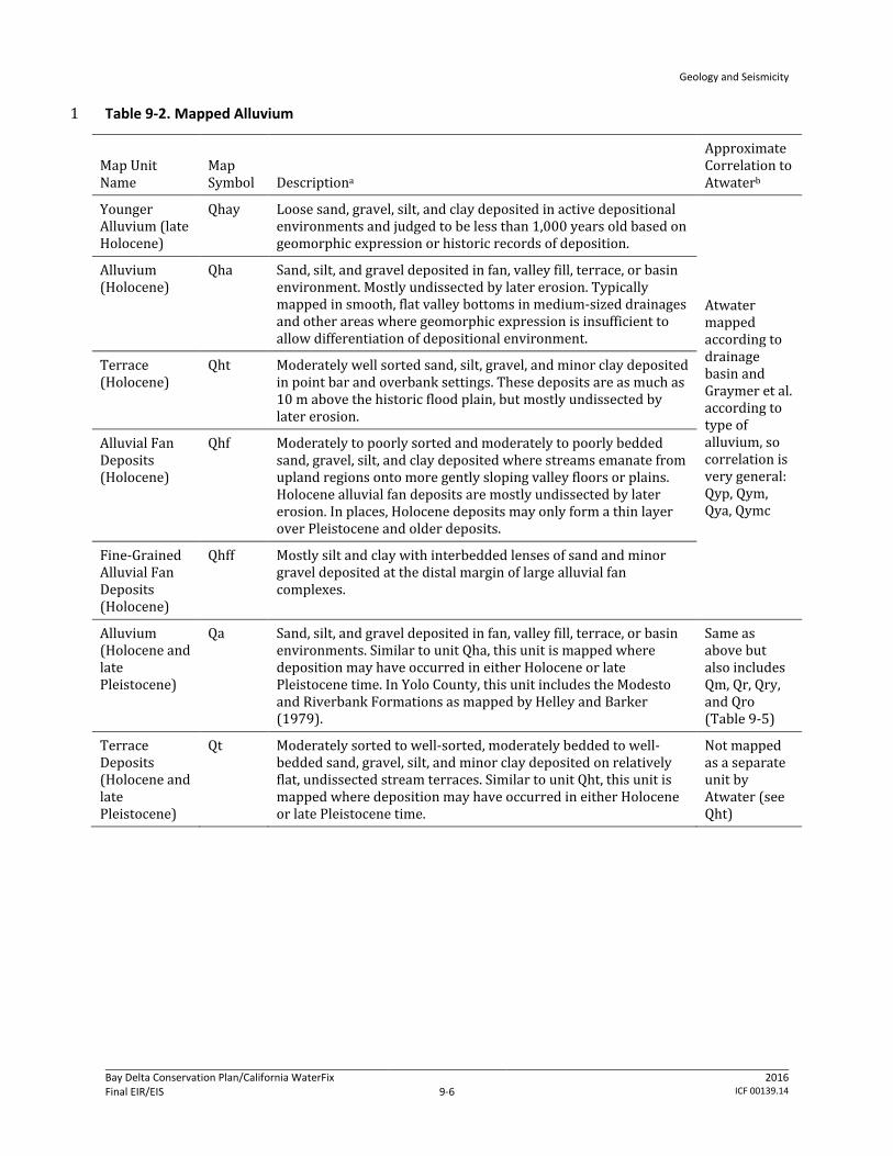
Alluvium is sediment deposited by a river or other running water, and is typically composed of a 4 variety of materials, including fine particles of silt and clay and larger particles of sand and gravel. 5 A river continually picks up and drops solid particles of rock and soil from its bed throughout its 6 length. Where river flow is fast, more particles are picked up than dropped. Where the river flow is 7 slow, more particles are dropped than are picked up. Areas where more particles are dropped are 8 called alluvial plains or floodplains, and the dropped particles are called alluvium. Even small 9 streams make alluvial deposits, but it is in the floodplains and deltas of large rivers where large, 10 geologically substantial alluvial deposits are found. The mapped Holocene alluvial deposits found in 11 the Delta and Suisun Marsh are described in Table 9-2. 12
Geology and Seismicity
Bay Delta Conservation Plan/California WaterFix Final EIR/EIS
Administrative Final 9-6
2016 ICF 00139.14
Table 9-2. Mapped Alluvium 1
Map Unit Name
Map Symbol Descriptiona
Approximate Correlation to Atwaterb
Younger Alluvium (late Holocene)
Qhay Loose sand, gravel, silt, and clay deposited in active depositional environments and judged to be less than 1,000 years old based on geomorphic expression or historic records of deposition.
Atwater mapped according to drainage basin and Graymer et al. according to type of alluvium, so correlation is very general: Qyp, Qym, Qya, Qymc
Alluvium (Holocene)
Qha Sand, silt, and gravel deposited in fan, valley fill, terrace, or basin environment. Mostly undissected by later erosion. Typically mapped in smooth, flat valley bottoms in medium-sized drainages and other areas where geomorphic expression is insufficient to allow differentiation of depositional environment.
Terrace (Holocene)
Qht Moderately well sorted sand, silt, gravel, and minor clay deposited in point bar and overbank settings. These deposits are as much as 10 m above the historic flood plain, but mostly undissected by later erosion.
Alluvial Fan Deposits (Holocene)
Qhf Moderately to poorly sorted and moderately to poorly bedded sand, gravel, silt, and clay deposited where streams emanate from upland regions onto more gently sloping valley floors or plains. Holocene alluvial fan deposits are mostly undissected by later erosion. In places, Holocene deposits may only form a thin layer over Pleistocene and older deposits.
Fine-Grained Alluvial Fan Deposits (Holocene)
Qhff Mostly silt and clay with interbedded lenses of sand and minor gravel deposited at the distal margin of large alluvial fan complexes.
Alluvium (Holocene and late Pleistocene)
Qa Sand, silt, and gravel deposited in fan, valley fill, terrace, or basin environments. Similar to unit Qha, this unit is mapped where deposition may have occurred in either Holocene or late Pleistocene time. In Yolo County, this unit includes the Modesto and Riverbank Formations as mapped by Helley and Barker (1979).
Same as above but also includes Qm, Qr, Qry, and Qro (Table 9-5)
Terrace Deposits (Holocene and late Pleistocene)
Qt Moderately sorted to well-sorted, moderately bedded to well-bedded sand, gravel, silt, and minor clay deposited on relatively flat, undissected stream terraces. Similar to unit Qht, this unit is mapped where deposition may have occurred in either Holocene or late Pleistocene time.
Not mapped as a separate unit by Atwater (see Qht)
Geology and Seismicity
Bay Delta Conservation Plan/California WaterFix Final EIR/EIS
Administrative Final 9-7
2016 ICF 00139.14
Map Unit Name
Map Symbol Descriptiona
Approximate Correlation to Atwaterb
Alluvial Fan Deposits (Holocene and late Pleistocene)
Qf Poorly sorted, moderately to poorly bedded sand, gravel, silt, and clay deposited in gently sloping alluvial fans. Similar to unit Qhf, this unit is mapped where deposition may have occurred in either Holocene or late Pleistocene time.
Atwater mapped according to drainage basin and Graymer et al. according to type of alluvium, so correlation is very general: Qo, Qom, Qoa, Qomc
Alluvium (late Pleistocene)
Qpa Poorly to moderately sorted sand, silt, and gravel in the Capay area (Esparto quadrangle). This unit is mapped on gently sloping to level alluvial fan or terrace surfaces where separate fan, terrace, and basin deposits could not be delineated. Late Pleistocene age is indicated by depth of stream incision, development of alfisols and lack of historical flooding.
Alluvial Fan Deposits (late Pleistocene)
Qpf Poorly sorted, moderately to poorly bedded sand, gravel, silt, and clay deposited in gently sloping alluvial fans. Late Pleistocene age is indicated by erosional dissection and development of alfisols. These deposits are about 10% denser and have 50% greater penetration resistance than unit Qhf (California Department of Conservation 2000).
Basin Deposits (late Pleistocene)
Qpb As mapped by Atwater (1982), older alluvium widely but sparsely exposed at the toe of the Putah Creek fan (Dozier quadrangle), most commonly in basins between stream-built ridges of younger alluvium.
Pediment Deposits (late and early Pleistocene)
Qop Thin deposits of sand, silt, clay, and gravel on broad, planar erosional surfaces. These deposits are extremely dissected, have well-developed soils, and are mostly tens or hundreds of meters above the current depositional surface.
Alluvium (late and early Pleistocene)
Qoa Sand, silt, clay, and gravel deposits with little or none of the original geomorphic expression preserved. Moderately to extremely dissected, in places tens or hundreds of meters above the current depositional surface, and capped by well-developed soils. In Yolo County, this unit includes the Red Bluff Formation as mapped by Helley and Barker (1979).
Source: Graymer et al. 2002. Note: Geologic units are listed in order of age (youngest to oldest). a Descriptions are taken directly from Graymer et al. 2002. b This correlation is only an approximation provided by the chapter author to aid the reader. It is not a
scientific or peer-reviewed analysis. 1
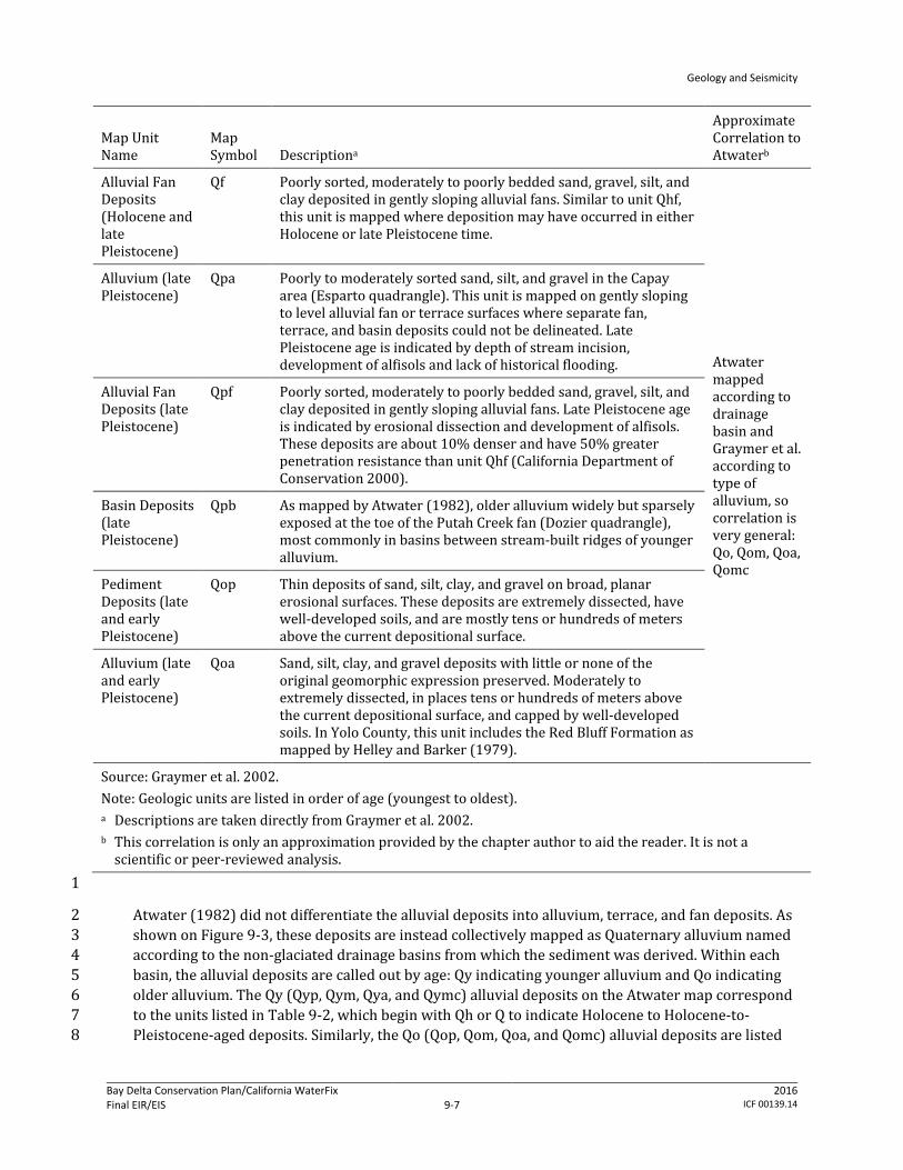
Atwater (1982) did not differentiate the alluvial deposits into alluvium, terrace, and fan deposits. As 2 shown on Figure 9-3, these deposits are instead collectively mapped as Quaternary alluvium named 3 according to the non-glaciated drainage basins from which the sediment was derived. Within each 4 basin, the alluvial deposits are called out by age: Qy indicating younger alluvium and Qo indicating 5 older alluvium. The Qy (Qyp, Qym, Qya, and Qymc) alluvial deposits on the Atwater map correspond 6 to the units listed in Table 9-2, which begin with Qh or Q to indicate Holocene to Holocene-to-7 Pleistocene-aged deposits. Similarly, the Qo (Qop, Qom, Qoa, and Qomc) alluvial deposits are listed 8

Geology and Seismicity
Bay Delta Conservation Plan/California WaterFix Final EIR/EIS
Administrative Final 9-8
2016 ICF 00139.14
in Table 9-2, with Qp indicating Pleistocene-aged alluvial deposits. Qch and Qcr, as mapped on the 1 Atwater map, consist of alluvial deposits from the Corral Hollow and Calaveras creek drainage 2 basins, respectively, and they are not broken out by age of deposits (Atwater 1982). 3
Levee and Channel Deposits 4
The ability of a river to carry sediment varies greatly with its flow volume and velocity. When a river 5 floods over its banks, the water spreads out, slows down, and deposits its load of suspended 6 sediment. Fine-grained sediment are deposited further from the channel, where coarser sediment 7 are deposited nearer the channel. Over time, the river’s banks are built up above the level of the rest 8 of the floodplain. The resulting low ridges are called natural levees. Artificial, or human-made, levees 9 are built to prevent flooding of lands along the river; these confine flow, resulting in higher and 10 faster water flow than would occur naturally. Artificial levees impact sedimentation in the modern 11 Delta. Natural and artificial levee deposits have been mapped and are described in Table 9-3. 12 Atwater did not separately map artificial channel, levee, and stream deposits. The natural levee, 13 floodplain, and flood basin deposits listed in Table 9-3 are designated as Ql, Qfp, and Qb, 14 respectively, on the Atwater map (Atwater 1982). 15
Table 9-3. Mapped Levee and Channel Deposits 16
Map Unit Name
Map Symbol Descriptiona
Approximate Correlation to Atwaterb
Artificial Channel Deposits (Historic)
ac Modified stream channels, usually where streams have been straightened and realigned. Deposits in artificial channels range from concrete in lined channels to sand and gravel similar to natural stream channel deposits (Qhc).
Not applicable
Artificial Levee Fill (Historic)
alf Man-made deposit of various materials and ages, forming artificial levees as much as 20 ft (6.5 m) high. Some are compacted and quite firm, but fills made before 1965 are almost everywhere not compacted and consist simply of dumped materials. Levees bordering waterways of the Sacramento/San Joaquin Delta, mudflats, and large streams were first emplaced as much as 150 years ago. The distribution of levee fill conforms to levees shown on the most recent U.S. Geological Survey 7.5-minute quadrangle maps
Not applicable
Stream Channel Deposits (Holocene)
Qhc Loose sand, gravel, and cobbles with minor clay and silt deposited within active, natural stream channels.
Not mapped as a separate unit by Atwater.
Natural Levee Deposits (Holocene)
Qhl Moderately to well-sorted sand with some silt and clay deposited by streams that overtop their banks during flooding. Natural levees are often identified by their low, channel-parallel ridge geomorphology.
Ql
Floodplain Deposits (Holocene)
Qhfp Medium- to dark-gray, dense, sandy to silty clay. Lenses of coarser material (silt, sand, and pebbles) may be locally present. Flood plain deposits usually occur between levee deposits (Qhl) and basin deposits (Qhb) and are prevalent in the Walnut Creek-Concord Valley, much of which is south of the map area.
Qfp

Geology and Seismicity
Bay Delta Conservation Plan/California WaterFix Final EIR/EIS
Administrative Final 9-9
2016 ICF 00139.14
Map Unit Name
Map Symbol Descriptiona
Approximate Correlation to Atwaterb
Floodbasin Deposits (Holocene)
Qhfb Firm to stiff silty clay, clayey silt, and silt, commonly with carbonate nodules and locally with black spherules (Mn and (or) Fe oxides). The deposits laterally grade into peaty mud and mud of tidal wetlands (unit Qhdm). Locally, the deposits are veneered with silty, reddish-brown alluvium of historic age, some of which may have resulted from hydraulic mining in the Sierra Nevada during the late 1800s.
Qb
Source: Graymer et al. 2002. Note: Geologic units are listed in order of age (youngest to oldest). a Descriptions are taken directly from Graymer et al. 2002. b This correlation is only an approximation provided by the chapter author to aid the reader. It is not a
scientific or peer-reviewed analysis. 1
Dune Sand Deposits 2
Dune sand deposits consist of very well-sorted fine to medium grained eolian (wind deposited) 3 sand. Holocene sand may discontinuously overlie the latest Pleistocene sand, both of which may 4 form a mantle of varying thicknesses over older materials. Most of the deposits are thought to be 5 associated with the latest Pleistocene to early Holocene periods of low sea level, during which large 6 volumes of fluvial (i.e., pertaining to a river or stream) and glacially derived sediment from the 7 Sierra were blown into the dunes. Dune sand deposits are described in Table 9-4. The Atwater map 8 refers to these dune sand as eolian deposits (Qe, Qm2e, and Qoe) (Atwater 1982). 9
Table 9-4. Mapped Dune Sand Deposits 10
Map Unit Name
Map Symbol Descriptiona
Approximate Correlation to Atwaterb
Dune Sand (early Holocene and latest Pleistocene)
Qds Very well sorted fine- to medium-grained eolian sand. They occur mainly in two large northwest-southeast trending sheets, as well as many small hills, most displaying Barchan morphology. Dunes display as much as 30 m of erosional relief and are presently being buried by basin deposits (Qhb) and delta mud (Qhdm). They probably began accumulating after the last interglacial high stand of sea level began to recede about 79 ka (Imbrie et al., 1984; Martinson et al., 1987; Hendy and Kennett, 2000), continued to form when sea level dropped to its Wisconsin minimum about 18 ka, and probably ceased to accumulate after sea level reached its present elevation (about 6 ka). Atwater (1982) recognized buried paleosols in the dunes, indicating periods of nondeposition.
Qe, Qm2e, Qoe
Source: Graymer et al. 2002. ka = thousand years. a Descriptions are taken directly from Graymer et al. 2002. b This correlation is only an approximation provided by the chapter author to aid the reader. It is not a
scientific or peer-reviewed analysis. 11
Geology and Seismicity
Bay Delta Conservation Plan/California WaterFix Final EIR/EIS
Administrative Final 9-10
2016 ICF 00139.14
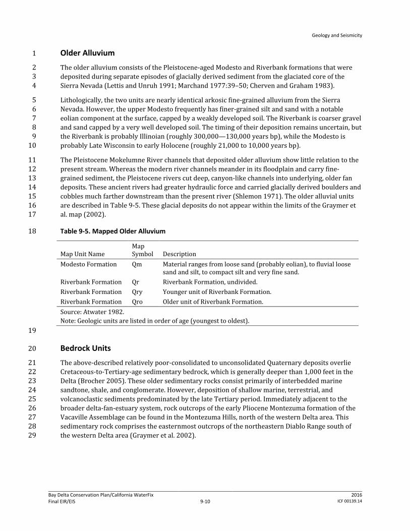
Older Alluvium 1
The older alluvium consists of the Pleistocene-aged Modesto and Riverbank formations that were 2 deposited during separate episodes of glacially derived sediment from the glaciated core of the 3 Sierra Nevada (Lettis and Unruh 1991; Marchand 1977:39–50; Cherven and Graham 1983). 4
Lithologically, the two units are nearly identical arkosic fine-grained alluvium from the Sierra 5 Nevada. However, the upper Modesto frequently has finer-grained silt and sand with a notable 6 eolian component at the surface, capped by a weakly developed soil. The Riverbank is coarser gravel 7 and sand capped by a very well developed soil. The timing of their deposition remains uncertain, but 8 the Riverbank is probably Illinoian (roughly 300,000—130,000 years bp), while the Modesto is 9 probably Late Wisconsin to early Holocene (roughly 21,000 to 10,000 years bp). 10
The Pleistocene Mokelumne River channels that deposited older alluvium show little relation to the 11 present stream. Whereas the modern river channels meander in its floodplain and carry fine-12 grained sediment, the Pleistocene rivers cut deep, canyon-like channels into underlying, older fan 13 deposits. These ancient rivers had greater hydraulic force and carried glacially derived boulders and 14 cobbles much farther downstream than the present river (Shlemon 1971). The older alluvial units 15 are described in Table 9-5. These glacial deposits do not appear within the limits of the Graymer et 16 al. map (2002). 17
Table 9-5. Mapped Older Alluvium 18
Map Unit Name Map Symbol Description
Modesto Formation Qm Material ranges from loose sand (probably eolian), to fluvial loose sand and silt, to compact silt and very fine sand.
Riverbank Formation Qr Riverbank Formation, undivided. Riverbank Formation Qry Younger unit of Riverbank Formation. Riverbank Formation Qro Older unit of Riverbank Formation. Source: Atwater 1982. Note: Geologic units are listed in order of age (youngest to oldest).
19
Bedrock Units 20
The above-described relatively poor-consolidated to unconsolidated Quaternary deposits overlie 21 Cretaceous-to-Tertiary-age sedimentary bedrock, which is generally deeper than 1,000 feet in the 22 Delta (Brocher 2005). These older sedimentary rocks consist primarily of interbedded marine 23 sandtone, shale, and conglomerate. However, deposition of shallow marine, terrestrial, and 24 volcanoclastic sediments predominated by the late Tertiary period. Immediately adjacent to the 25 broader delta-fan-estuary system, rock outcrops of the early Pliocene Montezuma formation of the 26 Vacaville Assemblage can be found in the Montezuma Hills, north of the western Delta area. This 27 sedimentary rock comprises the easternmost outcrops of the northeastern Diablo Range south of 28 the western Delta area (Graymer et al. 2002). 29

Geology and Seismicity
Bay Delta Conservation Plan/California WaterFix Final EIR/EIS
Administrative Final 9-11
2016 ICF 00139.14
9.1.1.3 Regional and Local Seismicity 1
The California Coast Ranges physiographic province lies along the complex boundary between two 2 tectonic plates: the North American Plate and the Pacific Plate. The geologic and tectonic conditions 3 in the Delta and Suisun Marsh have been, and continue to be, controlled primarily by the interaction 4 of these two massive blocks of the Earth’s crust. Under the current tectonic regime, the Pacific Plate 5 moves northwestward relative to the North American Plate at a rate of about 1.57 inches (40 6 millimeters) per year (Working Group on California Earthquake Probabilities 2003). Although 7 relative motion between these two plates is predominantly lateral (strike-slip), an increase in 8 convergent motion along the plate boundary within the past few million years has resulted in the 9 formation of mountain ranges and structural valleys of the Coast Ranges province (DeCourten 10 2008). 11
The San Andreas fault system dominates the seismicity of the region, and it comprises several major 12 faults including the San Andreas, Hayward–Rodgers Creek, Calaveras, Concord–Green Valley, and 13 Greenville faults. In addition to these major faults, many other named and unnamed regional faults 14 accommodate relative motion between the plates and relieve compressional stresses that also act 15 along the plate boundary. 16
The Delta and Suisun Marsh are in the eastern portion of the greater San Francisco Bay region, one 17 of the most seismically active areas in the United States. Since 1800, several earthquakes with 18 magnitudes greater than 6.5 have occurred in the immediate San Francisco Bay Area, including the 19 1868 magnitude 6.8 earthquake on the Hayward fault, the 1906 magnitude 7.9 San Francisco 20 earthquake on the San Andreas fault, and the more recent 1989 magnitude 6.9 Loma Prieta 21 earthquake that occurred in the Santa Cruz Mountains. Figure 9-5 depicts the recorded historical 22 seismicity in the San Francisco Bay region from 1800 to 2006. 23
Delta 24
Figure 9-5 indicates that the San Francisco Bay Area and Delta region have generally experienced 25 low-level seismicity since 1800. No earthquakes with magnitude greater than 5.0 have been 26 observed in the Delta. Buildings constructed in accordance with the California Building Code (CBC) 27 are not expected to experience major damage caused by an earthquake with a magnitude smaller 28 than 5.0. 29
As discussed in the following sections, the known active seismic sources located within the Delta 30 area are mostly blind thrust faults (described below). 31
Suisun Marsh 32
Similar to the Delta, Suisun Marsh has experienced low-level seismicity since 1800. A few 33 earthquakes with magnitudes between 3.0 and 4.9 were recorded in the proximity of the 34 Pittsburgh–Kirby Hills fault (Figure 9-5). Some of these seismic events may have occurred on the 35 fault. 36
Two earthquakes (the 1892 Vacaville-Winters and the 1983 Coalinga earthquakes) have been 37 associated with the Coast Ranges-Sierran Block (CRSB) seismic zone, a complex-dipping thrust fault 38 zone that goes through the Delta and Suisun Marsh area. The epicenter of the 1892 Vacaville-39 Winters earthquake was approximately 8 miles west of the Delta and Suisun Marsh. The epicenter of 40
Geology and Seismicity
Bay Delta Conservation Plan/California WaterFix Final EIR/EIS
Administrative Final 9-12
2016 ICF 00139.14
the 1983 Coalinga earthquake was approximately 110 miles south of the Delta. Both of these seismic 1 events had a magnitude greater than 6.5. 2
In 2003, the Working Group on California Earthquake Probabilities (WGCEP) calculated a 62% 3 probability for one or more large earthquakes (magnitude 6.7 or greater) to occur in the San 4 Francisco Bay region between 2002 and 2032). This estimate includes a 27% probability for one or 5 more earthquakes of magnitude 6.7 or greater to take place along the nearby Hayward–Rodgers 6 Creek fault over the same period. Because no major earthquakes have occurred in the San Francisco 7 Bay region over the last several years, this probability will increase with time because of the strain that 8 builds up along the faults (Working Group on California Earthquake Probabilities 2003). 9
The earthquake source model adopted by WGCEP in the 2003 study includes both the major 10 regional faults and the background seismicity. Because of uncertainties associated with the source 11 data, multiple earthquake source models were considered, and weights were assigned to these 12 models based on expert opinion. 13
Past Earthquake Ground Motion Intensity and Damage 14
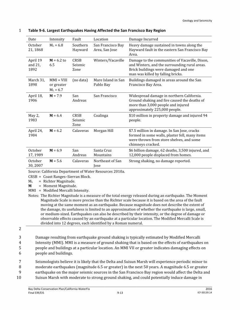
The San Francisco Bay region has been subjected to damaging ground shaking during past 15 earthquakes. Table 9-6 lists the largest earthquakes that have affected the San Francisco Bay region 16 since 1868 and the damage caused by these earthquakes, as described in the seismic study 17 (California Department of Water Resources 2007a). 18
Geology and Seismicity
Bay Delta Conservation Plan/California WaterFix Final EIR/EIS
Administrative Final 9-13
2016 ICF 00139.14
Table 9-6. Largest Earthquakes Having Affected the San Francisco Bay Region 1
Date Intensity Fault Location Damage Incurred October 21, 1868
ML = 6.8 Southern Hayward
San Francisco Bay Area, San Jose
Heavy damage sustained in towns along the Hayward fault in the eastern San Francisco Bay Area.
April 19 and 21, 1892
M = 6.2 to 6.5
CRSB Seismic Zone
Winters/Vacaville Damage to the communities of Vacaville, Dixon, and Winters, and the surrounding rural areas. Brick buildings were damaged and one man was killed by falling bricks.
March 31, 1898
MMI = VIII or greater ML = 6.7
(no data) Mare Island in San Pablo Bay
Buildings damaged in areas around the San Francisco Bay Area.
April 18, 1906
M = 7.9 San Andreas
San Francisco Widespread damage in northern California. Ground shaking and fire caused the deaths of more than 3,000 people and injured approximately 225,000 people.
May 2, 1983
M = 6.4 CRSB Seismic Zone
Coalinga $10 million in property damage and injured 94 people.
April 24, 1984
M = 6.2 Calaveras Morgan Hill $7.5 million in damage. In San Jose, cracks formed in some walls, plaster fell, many items were thrown from store shelves, and some chimneys cracked.
October 17, 1989
M = 6.9 San Andreas
Santa Cruz Mountains
$6 billion damage, 62 deaths, 3,500 injured, and 12,000 people displaced from homes.
October 30, 2007
M = 5.6 Calaveras Northeast of San Jose
Strong shaking, no damage reported.
Source: California Department of Water Resources 2010a. CRSB = Coast Ranges–Sierran Block. ML = Richter Magnitude. M = Moment Magnitude. MMI = Modified Mercalli Intensity. Notes: The Richter Magnitude is a measure of the total energy released during an earthquake. The Moment
Magnitude Scale is more precise than the Richter scale because it is based on the area of the fault moving at the same moment as an earthquake. Because magnitude does not describe the extent of the damage, its usefulness is limited to an approximation of whether the earthquake is large, small, or medium-sized. Earthquakes can also be described by their intensity, or the degree of damage or observable effects caused by an earthquake at a particular location. The Modified Mercalli Scale is divided into 12 degrees, each identified by a Roman numeral.
2
Damage resulting from earthquake ground shaking is typically estimated by Modified Mercalli 3 Intensity (MMI). MMI is a measure of ground shaking that is based on the effects of earthquakes on 4 people and buildings at a particular location. An MMI VII or greater indicates damaging effects on 5 people and buildings. 6
Seismologists believe it is likely that the Delta and Suisun Marsh will experience periodic minor to 7 moderate earthquakes (magnitude 6.5 or greater) in the next 50 years. A magnitude 6.5 or greater 8 earthquake on the major seismic sources in the San Francisco Bay region would affect the Delta and 9 Suisun Marsh with moderate to strong ground shaking, and could potentially induce damage in 10
Geology and Seismicity
Bay Delta Conservation Plan/California WaterFix Final EIR/EIS
Administrative Final 9-14
2016 ICF 00139.14
these areas. Strong ground shaking is typically expressed in terms of high peak ground accelerations 1 (the maximum acceleration by a soil particle at the ground surface during an earthquake). 2
Active Seismic Sources 3
Seismic sources or faults can generally be described by one of three activity classes as defined by 4 CGS: active, potentially active, or inactive. Active describes historical and Holocene faults that have 5 had displacements within the past 11,000 years. Potentially active describes faults showing 6 evidence of displacements during Quaternary time (the past 1.6 million years). Pre-Quaternary age 7 faults with no subsequent offset are classified as inactive. An inactive classification by CGS does not 8 mean that a fault will not rupture in the future, but only that it has not been shown to have ruptured 9 within the past 1.6 million years. Seismologists assume that the probability of fault rupture by 10 inactive faults is low. For this reason, only the potential seismic impacts from active or potentially 11 active faults are discussed in this chapter. 12
A recent seismic study (California Department of Water Resources 2007a) considered four 13 categories of active and potentially active seismic sources. 14
Crustal fault 15
Thrust fault 16
Seismic zone 17
Subduction zone 18
The characterization of these seismic sources is based on the latest geologic, seismologic, and 19 paleoseismic data, and the current understanding of fault behaviors is based mainly on the works of 20 the Working Group on Northern California Earthquake Potential (WGNCEP), WGCEP, and CGS 21 seismic source model used in the USGS National Seismic Hazard Maps (Working Group on Northern 22 California Earthquake Potential 1996; Working Group on California Earthquake Probabilities 2003; 23 Cao et al. 2003). 24
Key characteristics of the seismic sources important to the Delta and Suisun Marsh earthquake 25 hazard potential are summarized as follows: 26
Crustal Faults 27
The time-independent and time-dependent source models of active and potentially active seismic 28 sources in the San Francisco Bay region were considered in the seismic study (California 29 Department of Water Resources 2007a). The time-independent model assumes a Poissonian process 30 (i.e., a statistical probability distribution that characterizes discrete events occurring independently 31 of one another in time) for earthquake occurrence that is independent of the time since the last 32 earthquake. In contrast, in a time-dependent model, the likelihood of having an earthquake at a 33 specific future time depends on the elapsed time since the last earthquake; the longer the elapsed 34 time is, the greater the likelihood will be. In this study, the time-dependent source models were 35 applied to only seven major faults based on the rates of characteristic (maximum) events developed 36 by WGCEP (2003). These seven faults are the San Andreas, Hayward–Rodgers Creek, Calaveras, 37 Concord–Green Valley, San Gregorio, Greenville, and Mt. Diablo Thrust. 38
The approximate locations of the active and potentially active seismic sources in the San Francisco 39 Bay region and the Delta and Suisun Marsh are plotted in Figure 9-5. The surficial crustal faults 40
Geology and Seismicity
Bay Delta Conservation Plan/California WaterFix Final EIR/EIS
Administrative Final 9-15
2016 ICF 00139.14
known to cross the Delta and Suisun Marsh are the Pittsburgh–Kirby Hills and the Concord–Green 1 Valley faults. The Pittsburgh–Kirby Hills fault is mapped crossing the Suisun Marsh from near the 2 Fairfield at the north to the Pittsburg at the south. The Concord–Green Valley fault crosses along the 3 western part of Suisun Marsh. The Cordelia fault terminates close to the northern boundary of the 4 Suisun Marsh. 5
Other major crustal faults in the San Francisco Bay region that have the potential for generating 6 substantial earthquake ground shaking in the Delta and Suisun Marsh include the San Andreas, 7 Hayward–Rodgers Creek, Calaveras, Concord–Green Valley, and Greenville. The San Andreas, 8 Hayward–Rodgers Creek, and Calaveras faults are regional seismic sources that, although large 9 distances away from the Delta and Suisun Marsh, can induce considerable ground shaking because 10 of their potential for generating large-magnitude earthquakes. 11
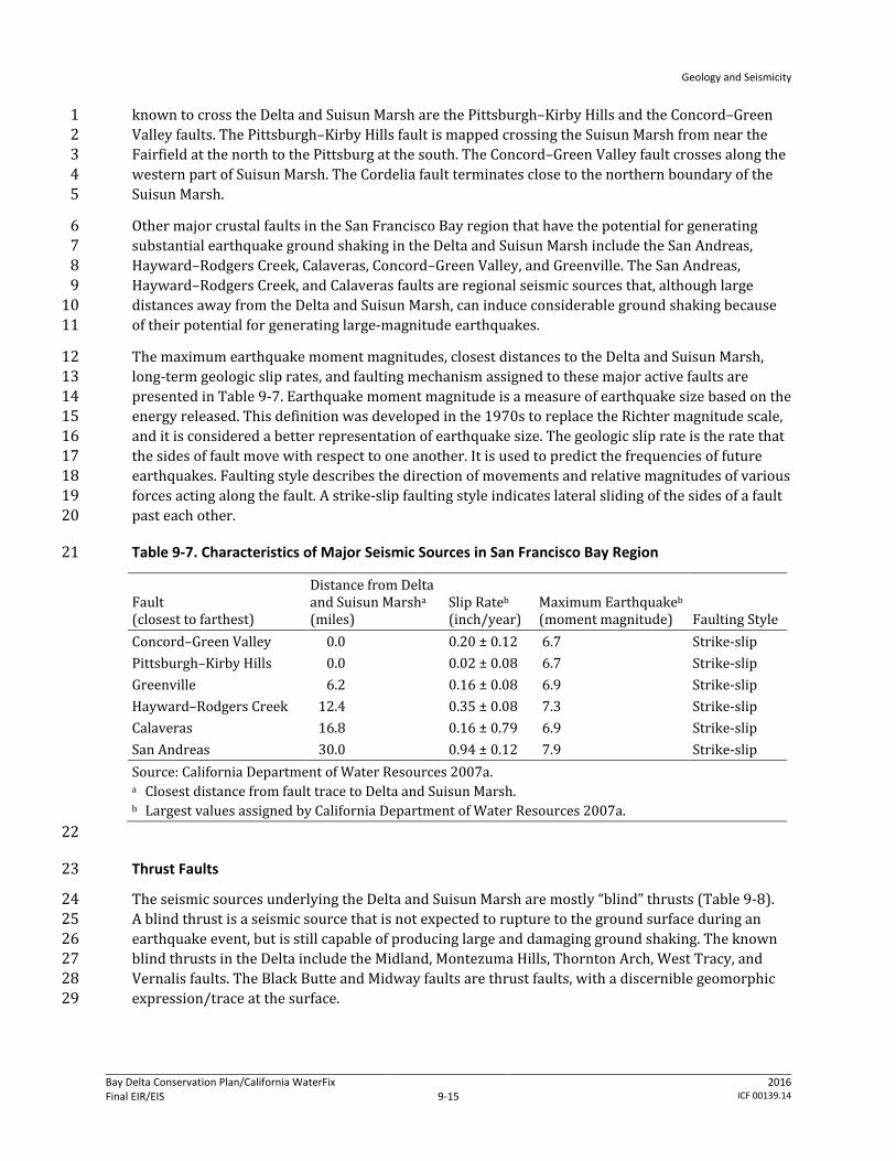
The maximum earthquake moment magnitudes, closest distances to the Delta and Suisun Marsh, 12 long-term geologic slip rates, and faulting mechanism assigned to these major active faults are 13 presented in Table 9-7. Earthquake moment magnitude is a measure of earthquake size based on the 14 energy released. This definition was developed in the 1970s to replace the Richter magnitude scale, 15 and it is considered a better representation of earthquake size. The geologic slip rate is the rate that 16 the sides of fault move with respect to one another. It is used to predict the frequencies of future 17 earthquakes. Faulting style describes the direction of movements and relative magnitudes of various 18 forces acting along the fault. A strike-slip faulting style indicates lateral sliding of the sides of a fault 19 past each other. 20
Table 9-7. Characteristics of Major Seismic Sources in San Francisco Bay Region 21
Fault (closest to farthest)
Distance from Delta and Suisun Marsha
(miles) Slip Rateb
(inch/year) Maximum Earthquakeb (moment magnitude) Faulting Style
Concord–Green Valley 0.0 0.20 ± 0.12 6.7 Strike-slip Pittsburgh–Kirby Hills 0.0 0.02 ± 0.08 6.7 Strike-slip Greenville 6.2 0.16 ± 0.08 6.9 Strike-slip Hayward–Rodgers Creek 12.4 0.35 ± 0.08 7.3 Strike-slip Calaveras 16.8 0.16 ± 0.79 6.9 Strike-slip San Andreas 30.0 0.94 ± 0.12 7.9 Strike-slip Source: California Department of Water Resources 2007a. a Closest distance from fault trace to Delta and Suisun Marsh. b Largest values assigned by California Department of Water Resources 2007a.
22
Thrust Faults 23
The seismic sources underlying the Delta and Suisun Marsh are mostly “blind” thrusts (Table 9-8). 24 A blind thrust is a seismic source that is not expected to rupture to the ground surface during an 25 earthquake event, but is still capable of producing large and damaging ground shaking. The known 26 blind thrusts in the Delta include the Midland, Montezuma Hills, Thornton Arch, West Tracy, and 27 Vernalis faults. The Black Butte and Midway faults are thrust faults, with a discernible geomorphic 28 expression/trace at the surface. 29

Geology and Seismicity
Bay Delta Conservation Plan/California WaterFix Final EIR/EIS
Administrative Final 9-16
2016 ICF 00139.14
Table 9-8. Characteristics of Thrust Faults in the Delta and Suisun Marsh 1
Fault (closest to farthest)
Probability of Activity
Slip Rate
(inch/year) Maximum Earthquake (moment magnitude) Faulting Style
Thornton Arch 0.2 0.002–0.006 6.0–6.5 Reverse-oblique* Montezuma Hills 0.5 0.002–0.02 6.0–6.5 Reverse-oblique Vernalis 0.8 0.003–0.02 6.25–6.75 Reverse-oblique Southern Midland 0.8 0.004–0.04 6.6 Reverse-oblique West Tracy 0.9 0.07–0.5 6.25–6.5 Reverse-oblique Black Butte and Midway 1.0 0.004–0.04 6.25–6.75 Reverse-oblique Northern Midland 1.0 0.004–0.04 6.0–6.5 Reverse-oblique Sources: California Department of Water Resources 2007a; Fugro Consultants 2011. * A reverse-oblique faulting style describes fault movements where one side of a fault moves upward
relative to the other side (up-dipping) with some components of lateral movement as a result of compression in the crust.
2
The Midland fault is an approximately north-striking fault that dips to the west and underlies the 3 central region of the Delta area. The fault is at least 37 miles long, and gas explorations conducted in 4 the area indicate that it is not exposed at the ground surface (California Division of Oil and Gas 5 1982). The Midland fault is divided into a Northern Midland fault zone, which characterizes the 6 northwest-striking fault splays north of Rio Vista, and a Southern Midland fault, which extends 7 southward to near Clifton Court Forebay. (The area (rather than a defined trace) referred to as the 8 Northern Midland fault zone is so-named because it encompasses numerous right-stepping 9 northwest-striking splays of the Midland fault.) 10
The Montezuma Hills seismic source is modeled as a source zone between the Delta and Suisun 11 Marsh near Rio Vista. The zone extends southward to the Sherman Island area and has been defined 12 to capture the potential active structures that may be responsible for the uplift of the Montezuma 13 Hills (California Department of Water Resources 2007a). 14
The Thornton Arch seismic zone has been defined to represent the possible existence of active 15 buried structures near the Thornton and West Thornton-Walnut Grove gas field near the Delta Cross 16 Channel area. After considering the best available evidence to date, the seismic study adopted a low 17 probability of activity and a low slip rate for this zone. The probability of activity is a measure of 18 certainty, based on the available data, that a seismic source is active (California Department of 19 Water Resources 2007a). The probability scale ranges from 0 to 1.0, with a probability of 1.0 20 strongly suggesting an active fault. 21
The West Tracy, Vernalis, Black Butte, and Midway faults are parts of the CRSB seismic zone 22 (California Department of Water Resources 2007a). As described previously in this section, the 23 CRSB is a complex zone of thrust faulting that defines the boundary between the Coast Ranges block 24 to the west and the Sierran basement rocks of the Sacramento and San Joaquin Valleys. The West 25 Tracy fault is mapped beneath the southwestern part of the Clifton Court Forebay and western part 26 of the Byron Tract Forebay. It has a total length of about 9.5 miles. Multiple east-dipping splays of 27 the fault may exist in the hanging wall (i.e., upthrown block) west of the Clifton Court Forebay, some 28 of which are underneath the intake channel to the Banks Pumping Plant (Fugro Consultants 2011). 29 The fault strikes in a northwest–southeast direction and dips westward moderately to steeply to the 30 west. The Vernalis fault is mapped at the southern end of the Delta area, extending between Tracy 31

Geology and Seismicity
Bay Delta Conservation Plan/California WaterFix Final EIR/EIS
Administrative Final 9-17
2016 ICF 00139.14
and Patterson, at a minimum length of about 19.2 miles. Similar to the West Tracy fault, the Vernalis 1 fault is a moderately to steeply west-dipping fault (California Department of Water Resources 2 2007a). The Black Butte fault is a northwest–southeast striking fault approximately 6 miles 3 southeast of Tracy. It dips moderately to steeply to the west. The Midway fault similarly strikes 4 northwest–southeast and is separated from the northwest end of the Black Butte fault by an en 5 echelon step across a small west–northwest-trending anticline. The seismic study (California 6 Department of Water Resources 2007a) characterized the Black Butte and Midway faults as a single 7 structure. 8
The probabilities of activity, maximum earthquake magnitudes, and long-term geologic slip rates 9 assigned to these blind thrusts are presented in Table 9-8. 10
Seismic Zones 11
To account for seismicity not associated with known faults, such as random or floating earthquakes, 12 two regional seismic zones—the Coast Ranges and Central Valley seismic zones—were developed 13 for the seismic study. The maximum earthquake magnitudes assigned to these seismic zones are 14 6.5 ± 0.3 moment magnitude. The recurrences of various earthquake magnitudes were estimated 15 using the historical seismicity recorded in each of the two seismic zones after removing events 16 within 10-kilometer-wide corridors along known faults (to avoid double counting seismic events 17 that occurred on the faults). Both the uniform and gridded seismicity source models were used to 18 model the uncertainty associated with earthquake location. In the uniform model, earthquakes are 19 assumed to occur everywhere within the zone with equal probability. For the gridded seismicity 20 model, the rates of earthquakes at a particular location within the zone are estimated using the 21 seismicity recorded around the location. A Gaussian (normal) filter was used to “smooth” the data 22 and to assign greater weights to nearby seismicity (California Department of Water Resources 23 2007a). 24
Subduction Zone 25
A subduction zone consists of interface and intraslab seismic sources. The interface seismic source is 26 along the convergent plate boundary, while the intraslab is a deeper seismic source on the 27 subducting plate. 28
The Cascadia subduction zone extends from Cape Mendocino, California, to Vancouver Island, British 29 Columbia. Although this seismic zone is a large distance from the Delta and Suisun Marsh, 30 its contributions to the ground shaking cannot be ignored because of its potential for generating 31 very large-magnitude earthquakes (earthquakes with moment magnitudes of about 9.0). 32
A large-magnitude earthquake tends to produce strong, long-period motions even at large distances 33 from the energy source. Long-period ground motions are important for assessments of linear 34 structures, such as tunnels and levee deformations. 35
Because of the distances from the Delta and Suisun Marsh, only the very large (megathrust) events 36 of the interface were considered in the seismic study (California Department of Water Resources 37 2007a). The Wong and Dober (2007) megathrust model was adopted, with a maximum moment 38 magnitude of 9 ± 0.5 and a recurrence interval of 450 ± 150 years. An alternative model was 39 considered by USGS for the Cascadia interface (Peterson et al. 2008). The 2007 USGS model 40 considers two weighted fault rupture scenarios. 41

Geology and Seismicity
Bay Delta Conservation Plan/California WaterFix Final EIR/EIS
Administrative Final 9-18
2016 ICF 00139.14
Megathrust events (magnitude 9.0 ± 0.2) that rupture the entire interface zone every 500 years 1 (weight of 0.67). 2
Smaller events (magnitude 8.0 to 8.7) that float over the interface zone and rupture the entire 3 zone over a period of about 500 years (weight of 0.33). 4
9.1.1.4 Geologic and Seismic Hazards 5
The geologic and seismic hazards discussed in this section include surface fault rupture, earthquake 6 ground shaking, seismic-induced liquefaction and its related soil instability, and slope instability. 7
Surface Fault Ruptures 8
Fault Trace and Rupture Zones 9
The Alquist-Priolo (AP) Earthquake Fault Zoning Act, passed in 1972, required the establishment of 10 earthquake fault zones (known as Special Studies Zones prior to January 1, 1994) along known active 11 faults in California. The state guidelines for assessing fault rupture hazards are explained in CGS 12 Special Publication 42, which is discussed in detail under Section 9.2, Regulatory Setting. Strict 13 regulations for development in these fault zones are enforced to reduce the potential for damage 14 resulting from fault displacement. 15
Special Publication 42 shows that the only AP fault zones occurring in the Plan Area are those for the 16 Green Valley and Cordelia faults. The active Green Valley fault crosses the southwestern corner of 17 the Suisun Marsh Restoration Opportunity Area (ROA) and the active Cordelia fault extends 18 approximately 1 mile into the northwestern corner of the Suisun Marsh ROA. 19
As discussed previously, the Delta is underlain by blind thrusts that are considered active or 20 potentially active, but they are not expected to rupture to the ground surface. Blind thrust fault 21 ruptures generally terminate before they reach the surface. They may produce ground 22 manifestations (i.e., below ground shear zone and/or ground surface bulging) during breaking, but 23 in most cases, no clear surface ruptures. 24
Those faults that could cause ground deformation at the surface but not surface rupture are 25 discussed in the following section. 26
Fault Offsets 27
An estimate of fault offset (displacement during a seismic event) is important for assessing possible 28 future effects. The amount of fault offset depends mainly on earthquake magnitude and location 29 along the fault trace. Fault offset can take place on a single fault plane, or displacements can be 30 distributed over a narrow zone. Fault rupture can also be caused by rupture on a neighboring fault 31 (secondary fault rupture). 32
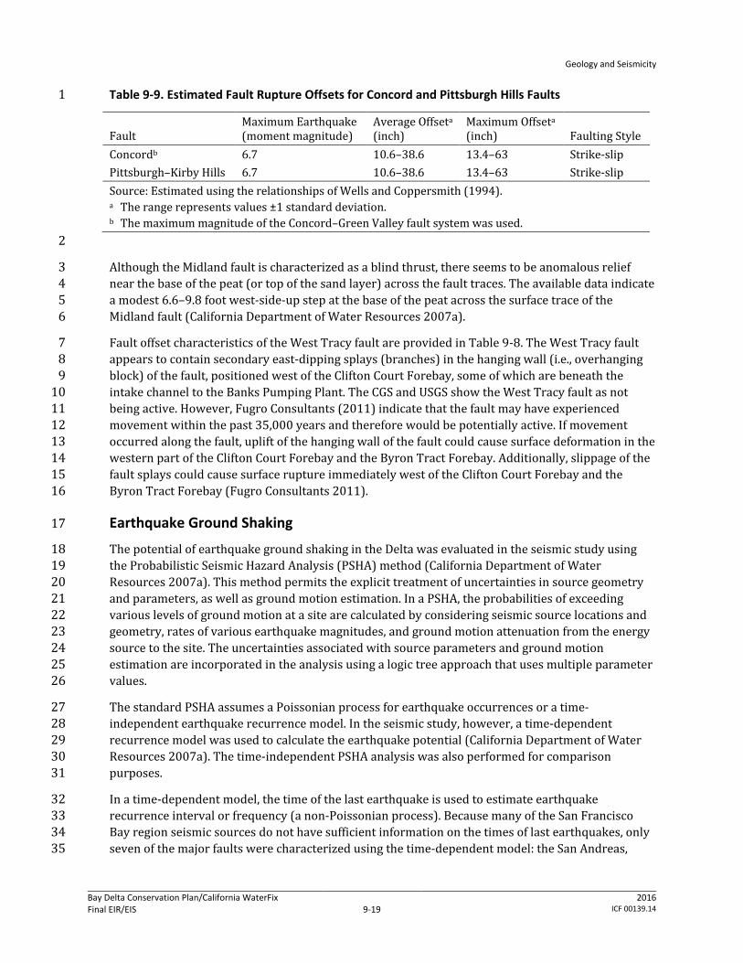
Empirical relationships are typically used to estimate fault offsets. The relationships provide 33 estimates of fault displacements, such as average and maximum offsets, as a function of fault 34 parameters. The average and maximum fault offsets for the Concord and Pittsburgh–Kirby Hills 35 faults (Table 9-9) were estimated using the relationships of Wells and Coppersmith (1994). 36
Geology and Seismicity
Bay Delta Conservation Plan/California WaterFix Final EIR/EIS
Administrative Final 9-19
2016 ICF 00139.14
Table 9-9. Estimated Fault Rupture Offsets for Concord and Pittsburgh Hills Faults 1
Fault Maximum Earthquake (moment magnitude)
Average Offseta (inch)
Maximum Offseta (inch) Faulting Style
Concordb 6.7 10.6–38.6 13.4–63 Strike-slip Pittsburgh–Kirby Hills 6.7 10.6–38.6 13.4–63 Strike-slip Source: Estimated using the relationships of Wells and Coppersmith (1994). a The range represents values ±1 standard deviation. b The maximum magnitude of the Concord–Green Valley fault system was used.
2
Although the Midland fault is characterized as a blind thrust, there seems to be anomalous relief 3 near the base of the peat (or top of the sand layer) across the fault traces. The available data indicate 4 a modest 6.6–9.8 foot west-side-up step at the base of the peat across the surface trace of the 5 Midland fault (California Department of Water Resources 2007a). 6
Fault offset characteristics of the West Tracy fault are provided in Table 9-8. The West Tracy fault 7 appears to contain secondary east-dipping splays (branches) in the hanging wall (i.e., overhanging 8 block) of the fault, positioned west of the Clifton Court Forebay, some of which are beneath the 9 intake channel to the Banks Pumping Plant. The CGS and USGS show the West Tracy fault as not 10 being active. However, Fugro Consultants (2011) indicate that the fault may have experienced 11 movement within the past 35,000 years and therefore would be potentially active. If movement 12 occurred along the fault, uplift of the hanging wall of the fault could cause surface deformation in the 13 western part of the Clifton Court Forebay and the Byron Tract Forebay. Additionally, slippage of the 14 fault splays could cause surface rupture immediately west of the Clifton Court Forebay and the 15 Byron Tract Forebay (Fugro Consultants 2011). 16
Earthquake Ground Shaking 17
The potential of earthquake ground shaking in the Delta was evaluated in the seismic study using 18 the Probabilistic Seismic Hazard Analysis (PSHA) method (California Department of Water 19 Resources 2007a). This method permits the explicit treatment of uncertainties in source geometry 20 and parameters, as well as ground motion estimation. In a PSHA, the probabilities of exceeding 21 various levels of ground motion at a site are calculated by considering seismic source locations and 22 geometry, rates of various earthquake magnitudes, and ground motion attenuation from the energy 23 source to the site. The uncertainties associated with source parameters and ground motion 24 estimation are incorporated in the analysis using a logic tree approach that uses multiple parameter 25 values. 26
The standard PSHA assumes a Poissonian process for earthquake occurrences or a time-27 independent earthquake recurrence model. In the seismic study, however, a time-dependent 28 recurrence model was used to calculate the earthquake potential (California Department of Water 29 Resources 2007a). The time-independent PSHA analysis was also performed for comparison 30 purposes. 31
In a time-dependent model, the time of the last earthquake is used to estimate earthquake 32 recurrence interval or frequency (a non-Poissonian process). Because many of the San Francisco 33 Bay region seismic sources do not have sufficient information on the times of last earthquakes, only 34 seven of the major faults were characterized using the time-dependent model: the San Andreas, 35

Geology and Seismicity
Bay Delta Conservation Plan/California WaterFix Final EIR/EIS
Administrative Final 9-20
2016 ICF 00139.14
Hayward–Rodgers Creek, Calaveras, Concord–Green Valley, San Gregorio, Greenville, and Mt. Diablo 1 Thrust. Therefore, the overall model used in the seismic study is not a pure time-dependent model. 2
Empirical earthquake ground motion attenuation relationship is used to estimate the horizontal 3 Peak Ground Acceleration (PGA) and the 5% damped spectral accelerations. The ground motion 4 attenuation relationship describes the attenuation of seismic waves with distance to the source as a 5 function of source parameters such as magnitude, rupture width, faulting style, and site condition. 6 Multiple relationships are commonly used to account for the uncertainty associated with ground 7 motion predictions. The PGA and spectral accelerations are engineering parameters representing 8 the intensity of seismic waves (ground motion) at various frequencies. 9
The seismic study used the Next Generation Attenuation (NGA) relationships developed for western 10 United States earthquakes for the crustal faults, blind thrusts, and seismic zones discussed 11 previously (California Department of Water Resources 2007a). At the time of the seismic study, only 12 three of the NGA relationship models were available, and these were used with equal weights (Chiou 13 and Youngs 2006; Campbell and Bozorgnia 2007; Boore and Atkinson 2007). For the Cascadia 14 subduction zone, the seismic study used the relationships of Youngs et al. (1997) and Atkinson and 15 Boore (2003). 16
The PSHA was conducted at six selected locations in the Delta area (Clifton Court, Delta Cross 17 Channel, Montezuma Slough, Sacramento, Sherman Island, and Stockton) for four different years: 18 2005, 2050, 2100, and 2200. The selected sites represent the north, south, east, west and central 19 regions of the Delta and the western-most section of the Plan Area. The results are expressed in 20 terms of hazard curves that relate the intensity of ground motion (PGA and response spectral 21 accelerations) to annual exceedance probability (probability that a specific value of ground motion 22 intensity will be exceeded). The distributions of hazard curve (the 5th, 15th, mean, median [50th], 23 85th, and 95th percentile hazard curves) were calculated at the six selected locations for PGA and 24 1.0-second spectral acceleration. The seismic hazard analysis was performed for a stiff soil site 25 condition, with an average shear-wave velocity of 1,000 feet per second (ft/sec) in the top 100 feet, 26 or 30 meters (Vs100ft). 27
The results of PSHA indicate that ground shaking hazards in the Delta area are not sensitive to the 28 assumed recurrence model (whether a time-dependent or time-independent model is used). This is 29 true because the hazards are dominated by the nearby Delta seismic sources (time-independent 30 sources), and not by the time-dependent major seismic source in the region. 31
Controlling Seismic Sources 32
The seismic sources expected to dominate the ground motions at a specific location (known as 33 controlling seismic sources) vary depending on the location, ground motion probability level (or 34 return period), and ground motion frequency (or period). Table 9-10 summarizes the controlling 35 seismic sources at the six selected sites in 2005 for PGA and 1.0-second spectral acceleration at 36 ground motion return periods of 100 and 2,475 years. 37

Geology and Seismicity
Bay Delta Conservation Plan/California WaterFix Final EIR/EIS
Administrative Final 9-21
2016 ICF 00139.14
Table 9-10. Controlling Seismic Sources in 2005 1
Location PGA 1.0-Second Spectral Acceleration 100-Year Return Period Clifton Court Southern Midland
Mt. Diablo Mt. Diablo Hayward–Rodgers Creek
Delta Cross Channel Southern Midland Northern Midland Zone
Mt. Diablo
Montezuma Slough Concord–Green Valley Concord–Green Valley Sacramento Northern Midland Zone Mt. Diablo
San Andreas Sherman Island Southern Midland Southern Midland
Hayward–Rodgers Creek San Andreas
Stockton Southern Midland Hayward–Rodgers Creek Calaveras
Hayward–Rodgers Creek San Andreas
2,475-Year Return Period Clifton Court Southern Midland Southern Midland Delta Cross Channel Southern Midland
Northern Midland Zone Cascadia Subduction Zone Southern Midland
Montezuma Slough Pittsburg-Kirby Hills Pittsburg-Kirby Hills Sacramento Northern Midland Zone Cascadia Subduction Zone Sherman Island Southern Midland
Montezuma Hills Zone Southern Midland
Stockton Southern Midland Cascadia Subduction Zone Source: California Department of Water Resources 2007a. PGA = Peak Ground Acceleration.
2
Additionally, the controlling seismic sources in 2200 are similar to those in 2005 except for the 1.0-3 second spectral acceleration; the San Andreas fault becomes a major contributor to the site hazards 4 because of the high potential for a repeat of a 1906-type major earthquake event. The controlling 5 seismic sources in 2050 and 2100 are similar to the sources identified for 2005 and 2200. 6
Site Soil Amplifications 7
Thick deposits of peaty and soft soil tend to amplify earthquake ground motions, especially for the 8 long-period motions such as the 1.0-second spectral acceleration. The earthquake ground motions 9 developed for the Delta and Suisun Marsh as part of the seismic study are applicable for a stiff soil 10 site condition. Therefore, these motions are expected to change as they propagate upward through 11 the peaty and soft soil from the stiffer alluvium underlying the Delta and Suisun Marsh. Based on 12 CALFED Bay-Delta Program (2000), the acceleration amplification factor from the stiff base layer to 13 the levee crown is in the order of 1 to 2. 14
72-Year Return Period Peak Ground Motion 15
The calculated mean PGA and 1.0-second spectral acceleration values for a 72-year ground motion 16 return period (or an annual frequency of 0.01388) in 2005 and 2200 are presented in Table 9-11. 17
Geology and Seismicity
Bay Delta Conservation Plan/California WaterFix Final EIR/EIS
Administrative Final 9-22
2016 ICF 00139.14
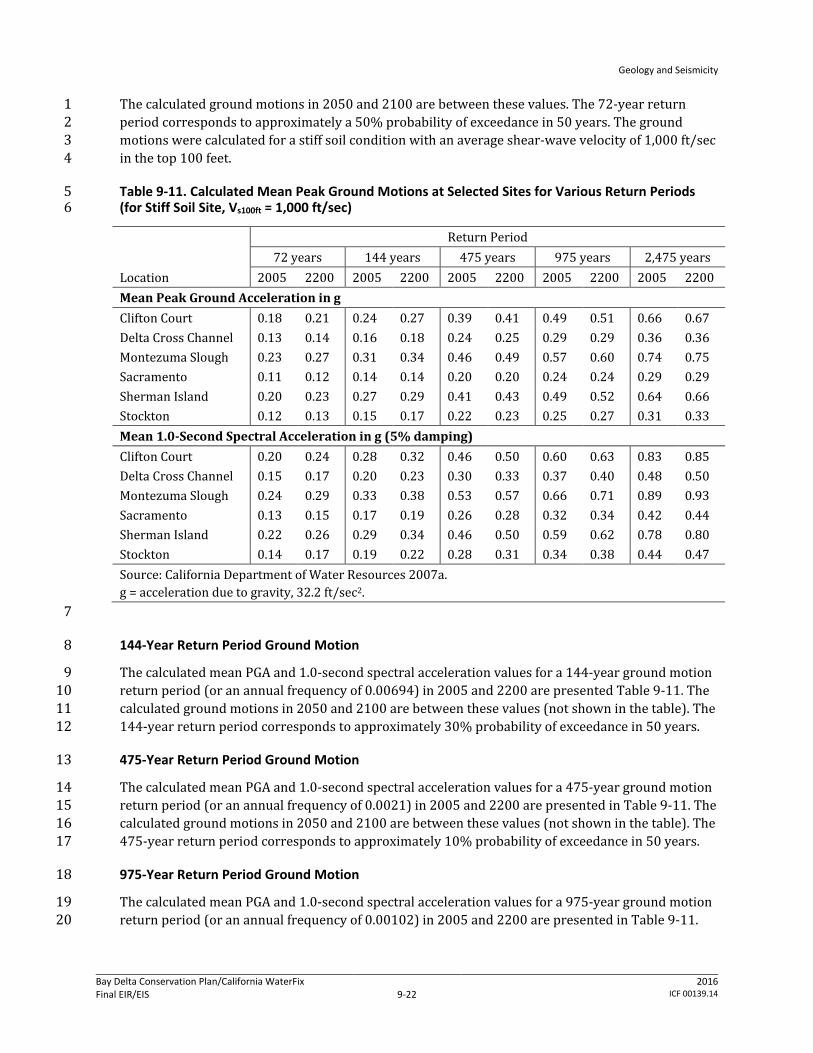
The calculated ground motions in 2050 and 2100 are between these values. The 72-year return 1 period corresponds to approximately a 50% probability of exceedance in 50 years. The ground 2 motions were calculated for a stiff soil condition with an average shear-wave velocity of 1,000 ft/sec 3 in the top 100 feet. 4
Table 9-11. Calculated Mean Peak Ground Motions at Selected Sites for Various Return Periods 5 (for Stiff Soil Site, Vs100ft = 1,000 ft/sec) 6
Location
Return Period 72 years 144 years 475 years 975 years 2,475 years
2005 2200 2005 2200 2005 2200 2005 2200 2005 2200 Mean Peak Ground Acceleration in g Clifton Court 0.18 0.21 0.24 0.27 0.39 0.41 0.49 0.51 0.66 0.67 Delta Cross Channel 0.13 0.14 0.16 0.18 0.24 0.25 0.29 0.29 0.36 0.36 Montezuma Slough 0.23 0.27 0.31 0.34 0.46 0.49 0.57 0.60 0.74 0.75 Sacramento 0.11 0.12 0.14 0.14 0.20 0.20 0.24 0.24 0.29 0.29 Sherman Island 0.20 0.23 0.27 0.29 0.41 0.43 0.49 0.52 0.64 0.66 Stockton 0.12 0.13 0.15 0.17 0.22 0.23 0.25 0.27 0.31 0.33 Mean 1.0-Second Spectral Acceleration in g (5% damping) Clifton Court 0.20 0.24 0.28 0.32 0.46 0.50 0.60 0.63 0.83 0.85 Delta Cross Channel 0.15 0.17 0.20 0.23 0.30 0.33 0.37 0.40 0.48 0.50 Montezuma Slough 0.24 0.29 0.33 0.38 0.53 0.57 0.66 0.71 0.89 0.93 Sacramento 0.13 0.15 0.17 0.19 0.26 0.28 0.32 0.34 0.42 0.44 Sherman Island 0.22 0.26 0.29 0.34 0.46 0.50 0.59 0.62 0.78 0.80 Stockton 0.14 0.17 0.19 0.22 0.28 0.31 0.34 0.38 0.44 0.47 Source: California Department of Water Resources 2007a. g = acceleration due to gravity, 32.2 ft/sec2.
7
144-Year Return Period Ground Motion 8
The calculated mean PGA and 1.0-second spectral acceleration values for a 144-year ground motion 9 return period (or an annual frequency of 0.00694) in 2005 and 2200 are presented Table 9-11. The 10 calculated ground motions in 2050 and 2100 are between these values (not shown in the table). The 11 144-year return period corresponds to approximately 30% probability of exceedance in 50 years. 12
475-Year Return Period Ground Motion 13
The calculated mean PGA and 1.0-second spectral acceleration values for a 475-year ground motion 14 return period (or an annual frequency of 0.0021) in 2005 and 2200 are presented in Table 9-11. The 15 calculated ground motions in 2050 and 2100 are between these values (not shown in the table). The 16 475-year return period corresponds to approximately 10% probability of exceedance in 50 years. 17
975-Year Return Period Ground Motion 18
The calculated mean PGA and 1.0-second spectral acceleration values for a 975-year ground motion 19 return period (or an annual frequency of 0.00102) in 2005 and 2200 are presented in Table 9-11. 20
Geology and Seismicity
Bay Delta Conservation Plan/California WaterFix Final EIR/EIS
Administrative Final 9-23
2016 ICF 00139.14
The calculated ground motions in 2050 and 2100 are between these values (not shown in the table). 1 The 975-year return period corresponds to approximately 5% probability of exceedance in 50 years. 2
2,475-Year Return Period Ground Motion 3
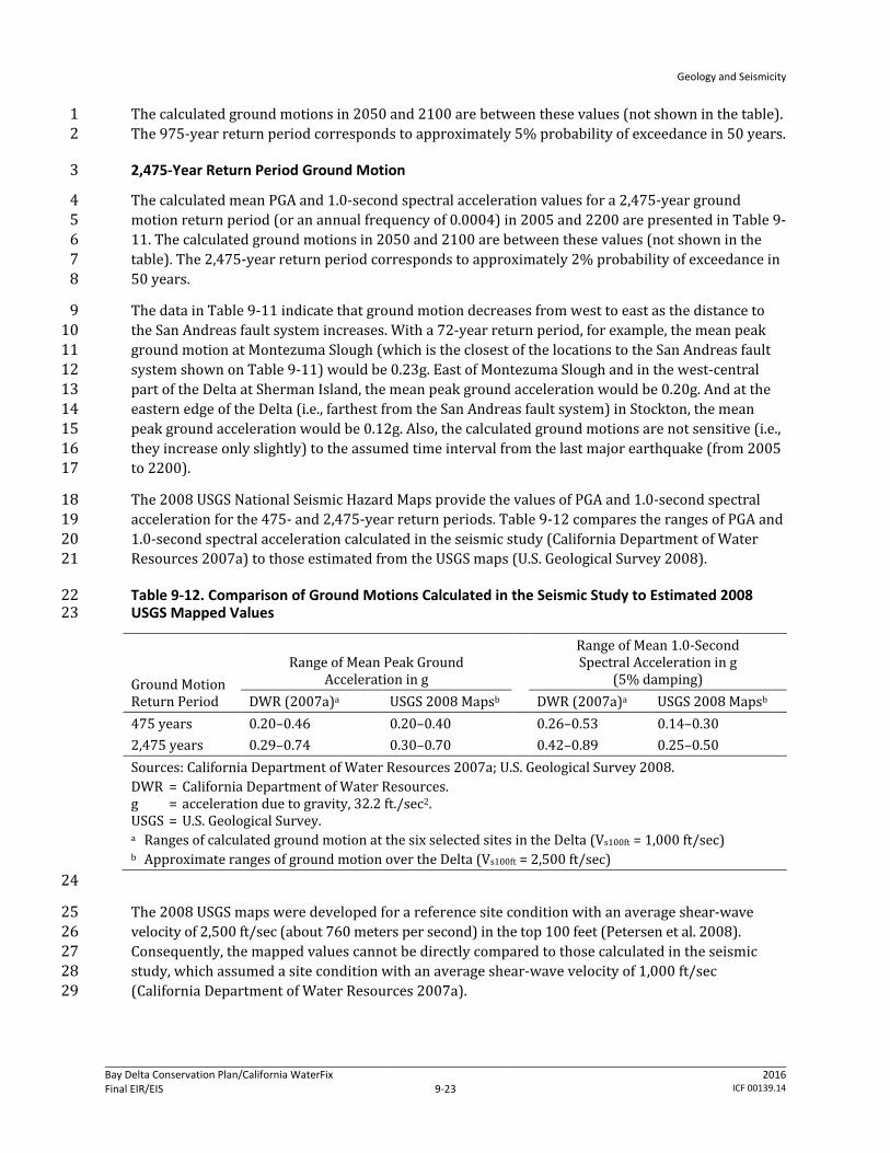
The calculated mean PGA and 1.0-second spectral acceleration values for a 2,475-year ground 4 motion return period (or an annual frequency of 0.0004) in 2005 and 2200 are presented in Table 9-5 11. The calculated ground motions in 2050 and 2100 are between these values (not shown in the 6 table). The 2,475-year return period corresponds to approximately 2% probability of exceedance in 7 50 years. 8
The data in Table 9-11 indicate that ground motion decreases from west to east as the distance to 9 the San Andreas fault system increases. With a 72-year return period, for example, the mean peak 10 ground motion at Montezuma Slough (which is the closest of the locations to the San Andreas fault 11 system shown on Table 9-11) would be 0.23g. East of Montezuma Slough and in the west-central 12 part of the Delta at Sherman Island, the mean peak ground acceleration would be 0.20g. And at the 13 eastern edge of the Delta (i.e., farthest from the San Andreas fault system) in Stockton, the mean 14 peak ground acceleration would be 0.12g. Also, the calculated ground motions are not sensitive (i.e., 15 they increase only slightly) to the assumed time interval from the last major earthquake (from 2005 16 to 2200). 17
The 2008 USGS National Seismic Hazard Maps provide the values of PGA and 1.0-second spectral 18 acceleration for the 475- and 2,475-year return periods. Table 9-12 compares the ranges of PGA and 19 1.0-second spectral acceleration calculated in the seismic study (California Department of Water 20 Resources 2007a) to those estimated from the USGS maps (U.S. Geological Survey 2008). 21
Table 9-12. Comparison of Ground Motions Calculated in the Seismic Study to Estimated 2008 22 USGS Mapped Values 23
Ground Motion Return Period
Range of Mean Peak Ground Acceleration in g
Range of Mean 1.0-Second Spectral Acceleration in g
(5% damping) DWR (2007a)a USGS 2008 Mapsb DWR (2007a)a USGS 2008 Mapsb
475 years 0.20–0.46 0.20–0.40 0.26–0.53 0.14–0.30 2,475 years 0.29–0.74 0.30–0.70 0.42–0.89 0.25–0.50 Sources: California Department of Water Resources 2007a; U.S. Geological Survey 2008. DWR = California Department of Water Resources. g = acceleration due to gravity, 32.2 ft./sec2. USGS = U.S. Geological Survey. a Ranges of calculated ground motion at the six selected sites in the Delta (Vs100ft = 1,000 ft/sec) b Approximate ranges of ground motion over the Delta (Vs100ft = 2,500 ft/sec)
24
The 2008 USGS maps were developed for a reference site condition with an average shear-wave 25 velocity of 2,500 ft/sec (about 760 meters per second) in the top 100 feet (Petersen et al. 2008). 26 Consequently, the mapped values cannot be directly compared to those calculated in the seismic 27 study, which assumed a site condition with an average shear-wave velocity of 1,000 ft/sec 28 (California Department of Water Resources 2007a). 29

Geology and Seismicity
Bay Delta Conservation Plan/California WaterFix Final EIR/EIS
Administrative Final 9-24
2016 ICF 00139.14
Liquefaction 1
Liquefaction is a process whereby strong ground shaking causes loose and saturated soil sediment 2 to lose strength and to behave as a viscous fluid. This process can cause excessive ground 3 deformations, failures, and temporary loss of soil bearing capacity, resulting in damage to structures 4 and levees. Ground failures can take the forms of lateral spreading, excessive differential and/or 5 total compaction or settlement, and slope failure. Liquefaction can also increase the potential for 6 buoyancy to buried structures (causing them to float toward the ground surface) and cause an 7 increase in lateral earth pressure. The Delta and Suisun Marsh are underlain at shallow depths by 8 various channel deposits and recent silty and sandy alluvium. Some of the existing levee materials 9 also consist of loose, silty, and sandy soil. Where saturated, the soil of the levee embankment and the 10 soil of the levee foundations locally may be susceptible to liquefaction during earthquakes. 11
Soil liquefaction is also a function of ground motion intensity and shaking duration. Longer ground 12 shaking, even at a lower intensity, may cause liquefaction as the soil is subject to more repeated 13 cycles of loading. Longer duration shaking is typically associated with larger magnitude 14 earthquakes, such as earthquakes that occur on the San Andreas, Hayward, and Calaveras faults. 15
Historical Occurrences of Liquefaction 16
Ground manifestation associated with liquefaction during the 1906 San Francisco earthquake was 17 reported in three locations within and in the vicinity of the Plan Area. Youd and Hoose (1978) 18 reported settlements up to 11 feet, south of Fairfield along the Southern Pacific Railway through the 19 Suisun Marsh; ground settlement of several inches was reported at the Southern Pacific Bridge 20 Crossing over the San Joaquin River in Stockton; and settlement of 3 feet was reported at a bridge 21 crossing over Middle River approximately 10 miles west of Stockton (Youd and Hoose 1978). No 22 ground manifestations were reported in the Delta and Suisun Marsh during the more recent 1989 23 Loma Prieta earthquake (Knudsen et al. 2000). 24
Conditions Susceptible to Liquefaction 25
Along the Delta and Suisun Marsh levees, loose silty and sandy soils are present in some of the levee 26 embankments and in the underlying foundation soil. When saturated, such soils are susceptible to 27 liquefaction during earthquake events. Since the levees are constructed (not naturally occurring), 28 the loose, silty and sandy soils comprising some of the levees are likely to be more continuous than 29 those present in the foundation of the levee (CALFED Bay-Delta Program 2000). Areas with larger 30 lateral continuity of liquefied soil are expected to experience more ground failure. The available data 31 also indicate that the levees protecting Sherman Island have extensive layers of liquefiable sandy 32 soil, more so than other levees in the Delta and Suisun Marsh (CALFED Bay-Delta Program 2000). 33 See Chapter 6, Surface Water, for more information. 34
Liquefaction Hazard Mapping 35
No official Seismic Hazard Zone maps for liquefaction potential have been developed by CGS or the 36 USGS for the soils of the entire Plan Area. Also, maps of liquefaction hazard (i.e., the susceptibility of 37 the geologic or soil materials and ground water levels to liquefaction combined with shaking levels 38 anticipated for a given earthquake scenario) have not been prepared for the entire Plan Area. 39 However, the vulnerability of Delta and Suisun Marsh levees to failure caused by seismic shaking 40 alone and by seismically induced liquefaction was analyzed in two Delta Risk Management Strategy 41 reports (California Department of Water Resources 2008a, b). These analyses recognized the 42

Geology and Seismicity
Bay Delta Conservation Plan/California WaterFix Final EIR/EIS
Administrative Final 9-25
2016 ICF 00139.14
following modes of seismically induced levee failure: 1) water overtopping a levee as a result of 1 levee crest slumping and settlement, 2) internal soil piping and erosion caused by earthquake-2 induced differential levee deformations, 3) sliding blocks and lateral spreading resulting in 3 transverse cracking, and 4) exacerbation of existing seepage problems due to levee deformations 4 and cracking. 5
The analyses grouped levees in the Delta and Suisun Marsh that are below the mean higher high 6 water floodplain into 22 failure vulnerability classes based on results from standard penetration test 7 blow count and cone penetration test blow count data, thickness of peat/organic soils underlying 8 the levees, and the steepness of the waterside of the levee slope. The 22 vulnerability classes were 9 then combined into three vulnerability groups: low, medium, and high, which are shown in Figure 9-10 6. The figure shows that many of the Delta levees are in the “high” vulnerability group and smaller 11 proportions of Delta levee are in the “low” and “medium” vulnerability groups. All of the Suisun 12 Marsh levees are in the “medium” vulnerability group. 13
Areas Susceptible to Slope Instability 14
A landslide is a mass of rock, soil, and/or debris that has been displaced downslope by sliding, 15 flowing, or falling. Landslides include cohesive block glides and disrupted slumps that have formed 16 by the translation or rotation of slope materials along one or more planar or curve-planar surfaces. 17 Soil creep is the slow, imperceptible downslope movement of weak soil and soft rock under the 18 force of gravity. 19
Landslides occur when shear stresses within a soil or rock mass exceed the available shear strength 20 of the mass. Failure may occur when stresses that act on a slope increase, internal strength of a slope 21 decreases, or a combination of both. Increased stresses can be caused by an increase in weight of the 22 overlying slope materials (by saturation), addition of material (surcharge) to the slope, application 23 of external loads (foundation loads, for example), or seismic loading (application of an earthquake-24 generated agitation to a structure). 25
Slope soil shear strength (the internal resistance of a soil to shear stress) can be reduced through 26 erosion and/or undercutting or removal of supporting materials at the slope toe as a result of 27 scouring (concentrated erosion by streamflow), increased pore water pressure within the slope, and 28 weathering or decomposition of supporting soil. Zones of low shear strength within the slope are 29 generally associated with the presence of certain clay, bedding, or fracture surfaces. The various 30 factors and processes that contribute to an unstable slope or levee in the Delta and Suisun Marsh are 31 explained in Chapter 6, Surface Water. 32
Strong earthquake ground shaking often causes landslides, particularly in areas already susceptible 33 to landslides because of other non-seismic factors, including the presence of existing landslide 34 deposits and water-saturated slope materials. Failure of steep slopes, collapse of natural 35 streambanks, and reactivation of existing landslides may occur extensively during a major 36 earthquake. 37
Historical Occurrences of Landslides and Levee Failure 38
Since 1900, at least 158 levee failures or breaches have been reported that resulted in flooding the 39 Delta and Suisun Marsh islands and tracts. (California Department of Water Resources 2010f) 40 Earthquake ground shaking is not linked to any of these levee breaches. The dominant causes of the 41 levee breaches are believed to have been water overtopping levees during high tides, erosion, piping 42
Geology and Seismicity
Bay Delta Conservation Plan/California WaterFix Final EIR/EIS
Administrative Final 9-26
2016 ICF 00139.14
and seepage though the levee embankment and foundation soil, and burrowing animals. (California 1 Department of Water Resources 2007b) 2
Because the topography of the Delta and Suisun Marsh is nearly level, the potential of landslides at 3 locations outside the levees is considered low. No maps or records on the historical occurrences of 4 slope failure are readily available for areas outside the levees. 5
Areas Susceptible to Landslides and Debris Flows 6
The known areas susceptible to slope failure within the Delta and Suisun Marsh primarily are along 7 the levee system and channel banks. Maps of those levees and channel banks that are particularly 8 subject to mass failure have not been prepared. 9
Because of their steep slopes, the Potrero Hills, the area west of Interstate I-680, and the western 10 slopes of the Montezuma Hills within the Suisun Marsh ROA likely have a greater relative potential 11 for landslides and debris flows (a shallow, moving mass of rock fragments, soil, and mud) than the 12 remainder of the Plan Area, although it is not known if any significant landslides or debris flows 13 have occurred in these areas. 14
A map in the Solano County General Plan, Public Health and Safety Element (Solano County 2008) 15 shows landslide susceptibility for the western part of the county. The landslide susceptibility ranges 16 from “least susceptible” to “most susceptible” in the part of the Plan Area west of I-680. The area 17 east of I-680 in the northwestern part of the Suisun Marsh is rated as “least susceptible”. The other 18 parts of the county, including the Montezuma Hills and Potrero Hills, appear not to have been 19 evaluated for landslide susceptibility. 20
Existing landslides (but not landslide susceptibility/hazard) have been mapped for all of Alameda 21 County (Roberts et al. 1999). Within and adjoining the Plan Area, the map shows one relatively small 22 landslide located east of the Delta Mendota Canal and southwest of Mountain House Creek. 23
In San Joaquin County, the sloping areas in the vicinity of the Plan Area exist southwest of the Plan 24 Area. The San Joaquin County General Plan (San Joaquin County 1992) shows no areas that are 25 subject to landslides within the Plan Area. 26
Landslide Hazard Maps Prepared by California Geological Survey 27
No official Seismic Hazard Zone maps for earthquake-induced landslide potential have been 28 developed by CGS for the Delta and Suisun Marsh. The closest available maps are those for the Las 29 Trampas Ridge USGS 7.5’ quadrangle, southwest of the Delta and Suisun Marsh, and the Livermore 30 and Altamont USGS 7.5’ quadrangles, south of the Delta and Suisun Marsh. The coverage areas of 31 these maps are outside of the Plan Area. 32
Ground Failure and Seismic-Induced Soil Instability 33
Compaction and Settlement 34
Earthquake ground motions can cause compaction and settlement of soil deposits because of 35 rearrangement of soil particles during shaking. The amount of settlement depends on ground 36 motion intensity and duration and degree of soil compaction; looser soil subjected to higher ground 37 shaking will settle more. Empirical relationships are commonly used to provide estimates of 38 seismic-induced settlement. In these relationships, ground shaking can be represented by PGA and 39
Geology and Seismicity
Bay Delta Conservation Plan/California WaterFix Final EIR/EIS
Administrative Final 9-27
2016 ICF 00139.14
magnitude, and soil compaction is typically measured by Standard Penetration Test (SPT) (i.e., an in-1 situ dynamic penetration test that measures the density of granular soil) blow-counts or N-values. 2 Excessive total and differential settlements can cause damage to buried structures, including 3 utilities, which in turn may initiate larger failure to levees and other above-ground facilities. 4
Loss of Bearing Capacity 5
Liquefaction can also result in temporary loss of bearing capacity in foundation soil, which has the 6 potential to cause foundation, pipeline, and tunnel failures during and immediately after an 7 earthquake event. 8
Lateral Spreading 9
Soil lateral spreading, or horizontal movement, can be initiated during an earthquake event. 10 Liquefaction-induced lateral spreading could occur even on gently sloping grounds or flat ground 11 with a nearby free face (e.g., a steep stream bank or other slope) when the underlying soil liquefies. 12 The amount of horizontal movement depends on ground motion intensity, the ground’s slope, soil 13 properties, and conditions of lateral constraint (free-face or non-free-face condition). 14
Increased Lateral Pressures 15
Liquefaction can increase lateral earth pressures on walls and buried structures. As soil liquefies, 16 earth lateral pressure will approach that of a fluid-like material. 17
Buoyancy 18
Liquefaction can cause buried pipes and structures to become buoyant. The potential for buoyancy 19 caused by liquefaction is typically determined using site-specific data at the planned locations of 20 buried pipes and structures. 21
Tsunami and Seiche 22
No known maps of tsunami hazard are available for the Delta or Suisun Marsh areas. Tsunami 23 hazard mapping closest to the Plan Area appears to be the tsunami inundation maps prepared by 24 the California Department of Conservation (2009) that extend east to about the Benicia Bridge. That 25 mapping shows at tsunami inundation area on the shores of the Sacramento River, extending east of 26 the Benicia Bridge to the edge of the base map (i.e., the Benicia 7.5’ quadrangle). The hazard maps 27 show the “maximum considered tsunami runup from a number of extreme, yet realistic tsunami 28 sources”. On the Benicia quadrangle, the inundation areas extend over mud flats and tidal marshes, 29 which are presumed to have an elevation at or within approximately 3 feet above sea level. Because 30 the inundation zone is close to sea level, it appears that substantial tsunami effects extending into 31 the Suisun Marsh and Delta are mostly attenuated in the San Francisco Bay. Tsunami effects to the 32 east of the Benicia Bridge are presumed to be further attenuated in the Suisun and Grizzly bays. 33
Historic records of the Bay Area indicate that 19 tsunamis were recorded in San Francisco Bay 34 during the period of 1868 to 1968. The maximum wave height recorded at the Golden Gate tide gage 35 was 7.4 feet (Contra Costa County 2009). 36
Based on a tsunami wave runup of 20 feet at the Golden Gate, the 2009 (Contra Costa) Countywide 37 Comprehensive Transportation Plan indicates that tsunami attenuation in the San Francisco Bay 38 would diminish the height of the wave to approximately 10 feet along the Richmond shoreline. East 39
Geology and Seismicity
Bay Delta Conservation Plan/California WaterFix Final EIR/EIS
Administrative Final 9-28
2016 ICF 00139.14
of Point Pinole, the wave height would diminish to approximately one-tenth of that (i.e., 2 feet) at 1 the Golden Gate (Contra Costa Transportation Agency 2009). 2
Based on the above information and on professional judgment, the effects of a tsunami in the Suisun 3 Marsh and Delta are expected to be minimal. 4
A seismically induced seiche is a rhythmic standing wave in a partly or fully enclosed body of water 5 caused by seismic waves generated by a landslide, earthquake-induced ground acceleration, or 6 ground offset. Elongate and deep (relative to width) bodies of water seem most likely to be subject 7 to seiches, and earthquake wave orientation may also play a role in seiche formation. The “sloshing” 8 waves generated can reach tens of feet high and have devastating effects on people and property. 9 Seiches can temporarily flood a shoreline in a manner similar to tsunami; however, their destructive 10 capacity is not as great. Seiches may cause overtopping of impoundments such as dams, particularly 11 when the impoundment is in a near-filled condition, releasing flow downstream. Earthquakes 12 occurring miles away can produce seiches in local bodies of water which could overtop and damage 13 levees and dams and cause water to inundate surroundings (Contra Costa County 2009). In 1868, an 14 earthquake along the Hayward fault in the San Francisco Bay Area generated a seiche along the 15 Sacramento River (County of Sacramento 1993). 16
Based on professional judgment, with the exception of the Clifton Court Forebay and the Byron Tract 17 Forebay, the hazard of a seiche occurring in the Plan Area is expected to be low because of the lack 18 of existing and proposed (e.g., intermediate forebay) deep, narrow, and enclosed water bodies and 19 distance from seismic sources capable of generating strong ground motions. 20
Fugro Consultants, Inc. (2011) identified the potential for strong ground motions along the West 21 Tracy fault to cause a seiche of an unspecified wave height to occur in the Clifton Court Forebay, 22 assuming that this fault is potentially active. Since the fault also extends under the Byron Tract 23 Forebay, a seiche could also potentially occur in the Byron Tract Forebay. 24
9.2 Regulatory Setting 25
9.2.1 Federal Plans, Policies, and Regulations 26
9.2.1.1 U.S. Geological Survey Quaternary Faults 27
USGS maintains the database of Quaternary fault and fold parameters (U.S. Geological Survey 2008). 28 The database is periodically updated to reflect the latest data available and current understanding of 29 fault behaviors. These parameters were used to develop the National Seismic Hazard Maps. 30
9.2.1.2 U.S. Geological Survey National Seismic Hazard Maps 31
USGS provides probabilistic seismic hazard maps for the 48 conterminous states, including the 32 Delta and Suisun Marsh area (U.S. Geological Survey 2008). These maps depict contour plots of PGA 33 and spectral accelerations at selected frequencies for various ground motion return periods. The 34 USGS National Seismic Hazard Maps are updated periodically and have been adopted by many 35 building and highway codes as the minimum design requirements. 36
Geology and Seismicity
Bay Delta Conservation Plan/California WaterFix Final EIR/EIS
Administrative Final 9-29
2016 ICF 00139.14
9.2.1.3 U.S. Geological Survey Landslide Hazard Program 1
USGS provides information regarding the causes of ground failure and mitigation strategies to 2 reduce long-term losses from landslide hazards. The information is useful for understanding the 3 nature and scope of ground failures and improving the mitigation strategies. 4
9.2.1.4 U.S. Army Corps of Engineers EC 1165-2-211 5
In July 2009, USACE issued EC 1165-2-211, a water resource policy mandating that every USACE 6 coastal activity influenced by tidal waters include potential relative sea level change in the starting 7 water surface elevation, where appropriate. To conform, projects must determine how sensitive 8 plans and designs are to rates of future local mean sea level change, how this sensitivity affects 9 calculated risk, and what design or operations and maintenance measures should be implemented 10 to minimize adverse consequences while maximizing beneficial effects. 11
The project is not a USACE activity subject to EC 1165-2-211; however, the project would include 12 maintenance operations that would require placement of levee materials as necessary to maintain 13 freeboard in response to actual sea level rise rates. 14
9.2.2 State Plans, Policies, and Regulations 15
9.2.2.1 Delta Plan 16
The Delta Reform Act requires that the Delta Plan promote effective emergency response and 17 emergency preparedness and promote appropriate land use to attempt to reduce risks to people, 18 property, and State interest in the Delta (Water Code Section 85305). The Delta Reform Act requires 19 the Delta Plan to recommend priorities for State investments in Delta levees. In response, the Delta 20 Plan has adopted policy RR P1, Prioritization of Statement Investments in Delta Levees and Risk 21 Reduction. 22
The hope is that implementation of Policy RR P1 will provide adequate protection to freshwater 23 aqueducts passing through the Delta and the primary freshwater channel pathways through the 24 Delta against floods and other risks of failures as well as prevent water deliveries to East Bay 25 Municipal Utilities District (EBMUD), Contract Costa Water District, the CVP and the SWP from being 26 interrupted by floods or earthquakes. 27
9.2.2.2 California Division of Safety of Dams 28
The DSOD has oversight and approval authority for structures that are considered dams under the 29 Water Code. Some levees are “dams” as defined by California Water Code Section 6002, and as such, 30 are required to meet DSOD’s standards and design review requirements. Dams under DSOD 31 jurisdiction are artificial barriers that are at least 25 feet high or have an impounding capacity of at 32 least 50 acre feet. Water Code Section 6004(c) specifically excludes structures in the Sacramento-33 San Joaquin Delta “…if the maximum possible water storage elevation of the impounded water does 34 not exceed four feet above mean sea level, as established by the United States Geological Survey 35 1929 Datum.” 36
Certain elements of various action alternatives could be subject to DSOD jurisdiction depending on 37 the size and volume of water stored (i.e., the intermediate forebay, the Byron Tract Forebay, repairs 38 or alterations to certain levees that might fall within DSOD jurisdiction). 39
Geology and Seismicity
Bay Delta Conservation Plan/California WaterFix Final EIR/EIS
Administrative Final 9-30
2016 ICF 00139.14
9.2.2.3 Liquefaction and Landslide Hazard Maps 1 (Seismic Hazards Mapping Act) 2
The Seismic Hazards Mapping Act of 1990 (California Public Resources Code Sections 2690 to 3 2699.6) was passed following the Loma Prieta earthquake to reduce threats to public health and 4 safety by identifying and mapping known seismic hazard zones in California. The act directs the CGS 5 of the Department of Conservation to identify and map areas prone to earthquake hazards of 6 liquefaction, earthquake-induced landslides, and amplified ground shaking. The purpose of the maps 7 is to assist cities and counties in fulfilling their responsibilities for protecting public health and 8 safety. The Act requires site-specific geotechnical investigations be conducted identifying the 9 seismic hazard and formulating mitigation measures prior to permitting most developments 10 designed for human occupancy within areas prone to liquefaction and earthquake-induced 11 landslides (also known as a Zone of Required Investigation). Cities and counties are required to 12 incorporate the Seismic Hazard Zone Maps into their Safety Elements and the Act requires sellers of 13 real property to disclose to buyers if property is in a seismic hazard Zone of Required Investigation. 14
As of January 2012, 119 official seismic hazard zone maps showing areas prone to liquefaction and 15 earthquake-induced landslides had been published in California, and more are scheduled. Most of 16 the mapping has been performed in southern California and the San Francisco Bay Area. Twenty-17 nine official maps for the San Francisco Bay Area have been released, with preparation of 10 18 additional maps for San Mateo, Santa Clara, Alameda, and Contra Costa Counties planned or in 19 progress. None of these planned or in-progress maps will cover the Plan Area. Accordingly, the 20 Seismic Hazards Mapping Act requirements will not affect the project unless and until the area is 21 mapped. 22
Review by the local agency is required for proposed construction sites located in the mapped 23 seismic hazard zones. Site-specific geologic investigations and evaluations are carried out to identify 24 the extent of hazards, and appropriate mitigation measures are incorporated in the development 25 plans to reduce potential damage. 26
9.2.2.4 Alquist-Priolo Earthquake Fault Zones 27
The AP Earthquake Fault Zoning Act was passed in 1972 (California Public Resources Code 28 Section 2621 et seq.). Similar to the Seismic Hazards Mapping Act, its main purposes are to identify 29 known active faults in California and to prevent the construction of buildings used for human 30 occupancy on the surface trace of active faults. For the purpose of this act, a fault is considered 31 active if it displays evidence of surface displacement during Holocene time (approximately during 32 the last 11,000 years). 33
The act directs CGS to establish the regulatory zones, called AP Earthquake Fault Zones, around the 34 known surface traces of active faults and to publish maps showing these zones. Each fault zone 35 extends approximately 200 to 500 feet on each side of the mapped fault trace to account for 36 potential branches of active faults. 37
CGS Special Publication 42 (Bryant and Hart 2007) states that in the absence of a site-specific 38 faulting study, the areas within 50 feet of the mapped fault should be considered to have the 39 potential for surface faulting and, therefore, no structure for human occupancy should be in these 40 areas. Construction of buildings intended for human occupancy within the fault zone boundaries is 41 strictly regulated, and site-specific faulting investigations are required. 42
Geology and Seismicity
Bay Delta Conservation Plan/California WaterFix Final EIR/EIS
Administrative Final 9-31
2016 ICF 00139.14
Title 14 of the California Code of Regulations (CCR), Section 3601(e), defines buildings intended for 1 human occupancy as those that would be inhabited for more than 2,000 hours per year. If none of 2 the facilities included within the proposed project design meet this definition, this act would not 3 apply. 4
9.2.2.5 Assembly Bill 1200 (Chapter 573, Statutes of 2005) 5
Assembly Bill 1200 directed DWR and the California Department of Fish and Wildlife to prepare a 6 report on evaluating the potential effects on water supplies derived from the Delta from a variety of 7 stressors, including continuous land subsidence, earthquakes, floods, and climate change,. The bill 8 also requires the studies of possible improvements and options (ranking of possible options) for the 9 water-related issues in the next 50, 100, and 200 years when determining effects on the Delta. 10
In response to the bill, DWR and the California Department of Fish and Wildlife have issued a report, 11 Risks and Options to Reduce Risks to Fishery and Water Supply Uses of the Sacramento/San Joaquin 12 Delta, dated January 2008. This report summarizes the potential risks to water supplies in the 13 Sacramento and San Joaquin Delta attributable to future subsidence, earthquakes, floods and climate 14 change, and identifies improvements to reduce the effects and options to deliver water. 15
9.2.2.6 Regulatory Design Codes and Standards for Project Structures 16
State and federal design codes and standards will regulate construction of the many structures that 17 are part of the proposed project. These codes and standards establish minimum design and 18 construction requirements, including design and construction of concrete and steel structures, 19 levees, tunnels, pipelines, canals, buildings, bridges and pumping stations. They also establish 20 construction requirements for temporary activities such as shoring of excavations and site grading. 21 The codes and standards are intended to ensure structural integrity and to protect public health and 22 safety. The codes and standards are developed by federal and state agencies with the participation 23 of engineering boards or associations, and professional engineering societies. They are based on the 24 performance history of structures under real conditions, including surface and subsurface geologic 25 conditions and variable regional conditions such as flooding and seismic events. The following state 26 and federal codes and standards will dictate the minimum design and construction requirements for 27 the various elements of the water conveyance facilities and the structural aspects of other 28 restoration actions. The minimum design and construction requirements act as performance 29 standards for engineers and construction contractors. Because the design and construction 30 parameters of these codes and standards are intended to reduce the potential for structural damage 31 or risks to human health due to the geologic and seismic conditions that exist within the Plan Area 32 and the surrounding region, their use is considered an environmental commitment of the agencies 33 implementing the proposed project. This commitment is discussed further in Appendix 3B, 34 Environmental Commitments, AMMs, and CMs. 35
American Association of State Highway and Transportation Officials (AASHTO) Guide 36 Specifications for LRFD [load and resistance factor] Seismic Bridge Design, 1st Edition, 2009. 37
Geotechnical seismic design guidelines are consistent with the philosophy for structure 38 design that loss of life and serious injury due to structure collapse are minimized, to the 39 extent possible and economically feasible. 40
These guide specifications adopt: 41
Geology and Seismicity
Bay Delta Conservation Plan/California WaterFix Final EIR/EIS
Administrative Final 9-32
2016 ICF 00139.14
7 percent probability of exceedance in 75 years (i.e., the same as 5 percent probability of 1 exceedance in 50 years and an approximately 1,000 year recurrence interval) for 2 development of a design spectrum. 3
the NEHRP Site Classification system and include site factors in determining response 4 spectrum ordinates. 5
a 1.5 safety factor (how much extra load beyond what is intended a structure will 6 actually take or be required to withstand) for minimum support length requirement to 7 ensure sufficient conservatism. 8
American Railway Engineering and Maintenance-of-Way Association Manual for Railway 9 Engineering, Volume 2, Chapter 9, Seismic Design for Railway Structures, 2008. 10
Provides recommended practices and guidelines for railway design in seismically active 11 areas as well as recommended practices for post-earthquake response, including 12 inspections. 13
Three performance limit states are given for seismic design of railroad bridges. 14
The serviceability limit state requires that the structure remain elastic during Level 1 15 ground motion (motion that has a reasonable probability of being exceeded during the 16 life of the bridge). Only moderate damage and no permanent deformations are 17 acceptable. 18
The ultimate limit state requires that the structure suffer only readily detectable and 19 repairable damage during Level 2 ground motion (motion that has a low probability of 20 being exceeded during the life of the bridge). 21
The survivability limit state requires that the bridge not collapse during Level 3 ground 22 motion (motion for a rare, intense earthquake). Extensive damage may be allowed. For 23 some structures, the railroad may elect to allow for irreparable damage, and plan to 24 replace the bridges following a Level 3 event. 25
No seismic analysis is necessary for locations where a base acceleration of 0.1 g or less is 26 expected with a 475-year return period. However, it is good practice to detail structures for 27 seismic resistance if they are in potentially active areas. 28
Structures classified as “important” (discussed in Section 1.3.3) should be designed to resist 29 higher seismic loads than nonimportant structures. 30
American Society of Civil Engineers Minimum Design Loads for Buildings and Other Structures, 31 ASCE/SEI 7-10, 2010. 32
Provides requirements for general structural design and includes means for determining 33 dead, live, soil, flood, wind, snow, rain, atmospheric ice, and earthquake loads, and their 34 combinations that are suitable for inclusion in building codes and other documents. 35
The intent of the seismic provisions in ASCE/SEI 7-10 is to provide a low probability of 36 collapse for buildings experiencing the Maximum Considered Earthquake (MCE) shaking. 37 MCE shaking is defined either as that shaking having a 2% probability of exceedance in 50 38 years (2,475 year mean recurrence interval) or at sites near major active fault, 150% of the 39 median shaking resulting from a characteristic magnitude earthquake on that fault, 40 whichever is less. 41
Geology and Seismicity
Bay Delta Conservation Plan/California WaterFix Final EIR/EIS
Administrative Final 9-33
2016 ICF 00139.14
Nonstructural components (including architectural, mechanical, electrical, and plumbing 1 equipment) and their supports and attachments that are permanently attached to a 2 structure must be designed and constructed to resist the effects of the earthquakes motions 3 in accordance with the code. 4
Provides Seismic Hazards Maps developed by USGS. Section 13.2.1 requires that mechanical 5 and electrical equipment manufacturers provide certification that components are 6 seismically qualified. Section 13.3.1 determines the magnitudes of horizontal and vertical 7 seismic forces. Use Ip = 1.5 for mechanical equipment and 1.75 for electrical equipment in 8 Occupancy Category IV for critical facilities as discussed in Section 4.3.5 9
California Building Standards Code, 2010 (Title 24 California Code of Regulations). 10
Provides seismic design requirements in the design and construction of buildings, 11 associated facilities and equipment. This code applies to all building occupancies, and 12 related features and equipment throughout the state, and contains requirements to the 13 structural, mechanical, electrical, and plumbing systems, and requires measures for energy 14 conservation, green design, construction and maintenance, fire and life safety, and 15 accessibility. 16
Caltrans (California Department of Transportation) Seismic Design Criteria (SDC), Version 1.6, 17 Nov 2010. 18
The SDC is a compilation of new and existing seismic design criteria for Ordinary bridges (a 19 bridge that spans less than 300 feet and is built on soil that is not susceptible to liquefaction, 20 lateral spreading, or scour. The document is an update of all the Structure Design (SD) 21 design manuals on a period basis to reflect the current state of practice for seismic bridge 22 design. 23
These specifications are meant to guarantee that an Ordinary bridge will remain 24 standing but may suffer significant damage requiring closure when ground shaking 25 (defined as ground motion time histories or response spectrum), liquefaction, lateral 26 spreading, surface fault rupture, and tsunami occur. 27
The criteria contained within the SDC are the minimum requirements for seismic design. 28
California Code of Regulations, Title 8. 29
Section 3203 (Cal/OSHA Workplace Injury and Illness Prevention Program) states that a 30 workplace or construction site must devise and implement an Injury and Illness Prevention 31 Program (IIPP) for all employees within the organization. The 8 required IIPP elements are: 32
Responsibility (e.g., supervisors are responsible for all accidents on their job or under 33 their supervision, supervisors are responsible for the inspection of work areas, 34 equipment and other potential accident producing conditions daily, employees are 35 responsible for ensuring that machine guards are used and maintained in good 36 condition and reporting to the supervisor if a guard is in questionable condition, etc.) 37
Compliance (e.g., supervisors must take disciplinary action when necessary to enforce 38 safety rules and practices, etc.) 39
Communication (e.g., company policy to maintain open communication between 40 management and employees on matters pertaining to safety, company will provide 41

Geology and Seismicity
Bay Delta Conservation Plan/California WaterFix Final EIR/EIS
Administrative Final 9-34
2016 ICF 00139.14
current safety news and activities, safety reading materials, signs, posters, and/or a 1 bulletin board and will hold regular safety meetings) 2
Hazard Assessment (e.g., managers, supervisors, and employees will report any 3 hazardous conditions or activities noted as a result of a formal weekly and/or monthly 4 inspections or during daily routine operations to the appropriate job site foreman or 5 superintendent) 6
Accident/Exposure Investigation (e.g., each supervisor/foreman has a prominent role in 7 promptly conducting an accident investigation and must collect the facts, determine the 8 sequence of events that resulted in the accident, identify action to prevent recurrence, 9 and provide follow-up to ensure that corrective action was effective) 10
Hazard Correction (e.g., all hazards will be corrected as soon as identified and a record 11 of hazard abatement will be kept in the main office to track the steps taken to correct 12 the hazardous condition) 13
Training and Instruction (e.g., all new employees must undergo an initial orientation on 14 job site safety rules and code of safe work practices. All employees must participate in 15 scheduled safety meetings which are conducted weekly by the site foreman on all job 16 sites and additional training as job duties or work assignments are expanded or 17 changed) 18
Recordkeeping (e.g., hazard reports, employee-training records, etc. will be kept at the 19 main office) 20
Section 1509 requires that every employer shall adopt a written Code of Safe Practices (8 21 CCR 1938, Appendix A) which related to the employer’s operations. Also, supervisory 22 employees must conduct Toolbox or Tailgate safety meetings, or equivalent, with their 23 crews at least every 10 working days to emphasize safety. 24
DWR (California Department of Water Resources) Division of Safety of Dams (DSOD) Guidelines 25 for Use of the Consequence-Hazard Matrix and Selection of Ground Motion Parameters, 2002. 26
The loading criteria for jurisdictional dam facilities are determined using the DSOD criteria 27 as follows: 28
The statistical level of ground motion for design (50th- or 84th-percentile) is determined 29 from the DSOD Consequence-Hazard Matrix based upon the consequence of failure 30 (Total Class Weight obtained from DSOD) and the slip rate of the causative fault 31 (obtained from a Seismic Hazard Assessment). 32
The Minimum Earthquake PGA parameter of 0.15g to 0.25g now applies to all new and 33 existing jurisdictional dams undergoing re-evaluation in California (new and existing 34 dams undergoing re-evaluation must resist a horizontal force of 0.15g to 0.25g). 35
DWR Division of Flood Management FloodSAFE Urban Levee Design Criteria, May 2012. 36
Provides engineering criteria and guidance for the design, evaluation, operation, and 37 maintenance of levees and floodwalls that provide an urban level of flood protection (i.e., 38 200-year level of flood protection) in California, as well as for determining design water 39 surface elevations (DWSE) along leveed and unleveed streams. Flood Safety Plan is required 40 for all agencies working at or near levee 41
Geology and Seismicity
Bay Delta Conservation Plan/California WaterFix Final EIR/EIS
Administrative Final 9-35
2016 ICF 00139.14
Requires analysis of seismic vulnerability of the levee system for 200-year return period 1 ground motions to meet the urban level of flood protection. 2
Frequently loaded levees (and floodwalls), such as many levees in the Sacramento-San 3 Joaquin Delta, are required to have seismic stability sufficient to maintain the integrity of the 4 levee and its internal structures without significant deformation. In most cases, for 5 frequently loaded levees with less than 5 feet of freeboard, earthquake-induced 6 deformations should be limited to less than 3 feet of total deformation and about 1 foot of 7 vertical displacement. 8
For intermittently loaded levees (and floodwalls), if seismic damage from 200-year-return-9 period ground motions is expected after the urban level of flood protection is achieved, a 10 post-earthquake remediation plan is required as part of a flood safety plan that is developed 11 in coordination with pertinent local, State, and federal agencies. 12
DWR Division of Engineering State Water Project—Seismic Loading Criteria Report, September 13 2012. 14
Provides DWR design guidelines in selecting appropriate seismic loading criteria for a wide 15 variety of SWP facilities including dams, canals, pipelines, tunnels, check structures, bridges, 16 buildings, pumping and power plants, and utility overcrossings. The seismic design load 17 shall be selected based on the criticality of a facility and consequences of failure. Most 18 critical facilities are expected to be functional immediately after an earthquake and thereby 19 should experience very limited damage. Other facilities may be considered less critical such 20 that they are designed to incur some damage but still return to some level of function in a 21 specified timeframe. 22
DWR Delta Seismic Design, June 2012. 23
This report serves to provide literature search of Delta specific design criteria and 24 application of load to structures. It’s a compilation of existing state of practice for the 25 seismic design of the type of hydraulic structures as well as recommended guidelines for 26 design criteria associated with future hydraulic structures in the Delta. 27
Federal Highway Administration Seismic Retrofitting Manual for Highway Structures, Parts 1 28 and 2, 2006. 29
The manual recommends a performance-based methodology for retrofitting highway 30 bridges. It defines different performance expectations for bridges of varying importance 31 while subject to four different levels of seismic hazard. The manual goes on and provides 32 more details for defining minimal, significant, and sustained damages. It is worth noting that 33 the performance levels are varying with level of earthquake ground motion, bridge 34 importance and anticipated service life (ASL). Two ground motion levels (lower level – 100 35 year return period and upper level – 975 year return period), two importance classifications 36 (Standard and Essential), and three service life categories (ASL l, 2, and 3) are defined. 37
Minimum performance levels for retrofitted bridges: 38

Geology and Seismicity
Bay Delta Conservation Plan/California WaterFix Final EIR/EIS
Administrative Final 9-36
2016 ICF 00139.14
Earthquake Ground Motion
Bridge Importance and Service Life Category Standard Essential
ASL1 ASL2 ASL3 ASL1 ASL2 ASL3 Lower Level Ground Motion 50 percent probability of exceedance in 75 years; return period is about 100 years.
PL0 PL3 PL3 PL0 PL3 PL3
Upper Level Ground Motion 7 percent probability of exceedance in 75 years; return period is about 1,000 years.
PL0 PL1 PL1 PL0 PL1 PL2
1. Anticipated Service Life categories are: a. ASL 1: 0-15 years b. ASL 2: 16-50 years c. ASL 3: greater than 50 years
2. Performance Levels are: a. PL0 – No minimum level of performance is recommended. b. PL1 – Life safety. Significant damage is sustained during an earthquake and service is significantly disrupted,
but life safety is assured. The bridge may need to be replaced after a large earthquake. c. PL2 – Operational. Damage sustained is minimal and full service for emergency vehicles should be available
after inspection and clearance of debris. Bridge should be reparable with or without restrictions on traffic flow.
d. PL3 – Fully operational. Damage sustained is negligible and full service is available for all vehicles after inspection and clearance of debris. Any damage is repairable without interruption to traffic.
3. Earthquake ground motion levels a. The “lower level” earthquake ground motion is one that has a reasonable likelihood of occurrence within the
life of the bridge (assume to be 75 years) (i.e., it represents a relatively small but likely ground motion) b. The “upper level” earthquake ground motion has a finite, but remote, probability of occurrence within the life
of the bridge; i.e., it represents a large but unlikely ground motion. 4. An “essential” bridge is one that satisfies one or more of the following conditions:
a. Required to provide secondary life safety (provides access to local emergency services such as hospitals or cross routes that provide secondary life safety.)
b. Loss of the bridge would create a major economic impact c. Formally defined by a local emergency plan as critical (enables civil defense, fire departments, and public
health agencies to respond immediately to disaster situations) d. Serves as a critical link in the security and/or defense roadway network. e. A “standard” bridge is everything not “essential”
1
State of California Sea-Level Rise Task Force of the Coastal and Ocean Working Group of the 2 California Climate Action Team (CO-CAT), Sea-Level Rise Interim Guidance Document, 2010. 3
This document provides guidance for incorporating sea level rise projections into planning 4 and decision making for projects in California. Using Year 2000 as a baseline, the sea level 5 rise projections in California range between 10 and 17 inches by year 2050 and between 18 6 and 29 inches by year 2070. 7
Underestimating sea level rise in the project design will result in harmful realized impacts 8 such as flooding. Harmful impacts are more likely to occur if the project design is based 9 upon a low projection of sea level rise and less likely if higher estimates of sea level rise are 10 used. In situations with high consequences (high impacts and/or low adaptive capacity), 11 using a low sea level rise value involves a higher degree of risk. (Examples of harmful 12 impacts that might result from underestimating sea level rise include damage to 13 infrastructure, contamination of water supplies due to saltwater intrusion, and inundation 14 of marsh restoration projects located too low relative to the tides). 15
Geology and Seismicity
Bay Delta Conservation Plan/California WaterFix Final EIR/EIS
Administrative Final 9-37
2016 ICF 00139.14
As of the date of the guidance document, the State Coastal Conservancy (SCC) and the State 1 Lands Commission (SLC) have adopted, and the Delta Vision Blue Ribbon Task Force 2 Independent Science Board has recommended, the use of 55 inches (140 cm) of sea level 3 rise for 2100. The SCC and the SLC also adopted a policy of using 16 inches (41 cm) as the 4 estimate of sea level rise for 2050. Agencies may select other values depending on their 5 particular guiding policies and considerations related to risk, ability to incorporate phased 6 adaptation into design and other factors. 7
USACE (CESPK-ED-G), Geotechnical Levee Practice, SOP EDG-03, 2004. 8
This procedure covers the geotechnical practice for levee evaluation, analysis, design, 9 construction and maintenance of levees in accordance with Sacramento District and USACE 10 guidance and regulation. Sacramento District standard practice may differ from published 11 USACE guidance. 12
Standard Levee Geometry – The minimum levee section should have a 3H:1V waterside 13 slope, a minimum 20 ft. wide crown for main line levees, major tributary levees, and bypass 14 levees, a minimum 12 ft. wide crown for minor tributary levees, a 3H:1V landside slope, a 15 minimum 20 ft. wide landside easement, and a minimum 15 ft. waterside easement. Existing 16 levees with landside slopes as steep as 2H:1V may be used in rehabilitation projects if 17 landside slope performance has been good. Easements are necessary for maintenance, 18 inspection, and floodfight access. 19
Typically a seepage berm should be designed as a semipervious berm with a drainage layer. 20 Seepage berms should have a minimum width of 4 times the maximum levee height in a 21 reach. The maximum seepage berm width should typically be 300 ft. A seepage berm will 22 typically vary from about 5 ft. thick at the levee toe to about 3 ft. thick at the berm toe. 23
USACE Design and Construction of Levees, EM 1110-2-1913, 2000. 24
This document provides guidelines or methodology for the design and construction of earth 25 levees. 26
The manual is general in nature and not intended to supplant the judgment of the design 27 engineer on a particular project. 28
USACE Engineering and Design—Earthquake Design and Evaluation for Civil Works Projects, 29 ER 1110-2-1806, 1995. 30
The manual provides guidance in evaluating and assessing the ground motions, site 31 characterization, structural response, functional consequences, and potential hazards in the 32 design and construction of Civil Work projects including dams and levees. 33
The seismic design for new projects and the seismic evaluation or reevaluation for existing 34 projects should be accomplished in accordance with this regulation. This regulation applies 35 to all projects which have the potential to malfunction or fail during major seismic events 36 and cause hazardous conditions related to loss of human life, appreciable property damage, 37 disruption of lifeline services, or unacceptable environmental consequences. The scope of 38 each seismic study should be aimed at assessing the ground motions, site characterization, 39 structural response, functional consequences, and potential hazards in a consistent, well-40 integrated, and cost-effective effort that will provide a high degree of confidence in the final 41 conclusions. 42

Geology and Seismicity
Bay Delta Conservation Plan/California WaterFix Final EIR/EIS
Administrative Final 9-38
2016 ICF 00139.14
Survival of operating equipment and utility lines is as essential as survival of the structural 1 and geotechnical features of the project. 2
USACE Engineering and Design – Earthquake Design and Evaluation of Concrete Hydraulic 3 Structures, EM 1110-2-6053, 2007. 4
This manual provides guidance for performance-based design and evaluation of concrete 5 hydraulic structures (CHS). It introduces procedures that show how to design or evaluate a 6 hydraulic structure to have a predictable performance for specified levels of seismic hazard. 7 Traditional design and evaluation procedures may still be used for feasibility and screening 8 purposes. However, for critical facilities, they should be followed by the procedures of this 9 manual to prevent sudden collapse even though the structure may suffer severe damage, to 10 limit damage to a repairable level, or to maintain functionality immediately after the 11 earthquake. 12
This manual contains mandatory requirements at the end of each chapter. These 13 requirements usually pertain to critical elements of the design and evaluation, such as loads 14 and load combinations, to analytical procedures used to determine force and displacement 15 demands, and to methods used to determine member strength and displacement capacities. 16 The purpose of the mandatory requirements is to assure that the structure meets minimum 17 safety and performance objectives. 18
Performance requirements for stability shall be in accordance with EM 1110-2-2100, 19 Stability Analysis of Concrete Structures. 20
USACE Engineering and Design—General Design and Construction Considerations for Earth and 21 Rock-Fill Dams, EM 1110-2-2300, 2004. 22
This manual provides guidance on the design and construction, and performance 23 monitoring of and modifications to embankment dams. The manual presents general 24 guidance and is not intended to supplant the creative thinking and judgment of the designer 25 for a particular project. 26
To meet the dam safety requirements, the design, construction, operation, and modification 27 of an embankment dam must comply with the following technical and administrative 28 requirements: 29
Technical requirements 30
The dam, foundation, and abutments must be stable under all static and dynamic 31 loading conditions 32
Seepage through the foundation, abutments, and embankment must be controlled 33 and collected to ensure safe operation. The intent is to prevent excessive uplift 34 pressures, piping of materials, sloughing, removal of material by solution, or erosion 35 of this material into cracks, joints, and cavities. In addition, the project purpose may 36 impose a limitation on allowable quantity of seepage. The design should include 37 seepage control measures such a foundation cutoffs, adequate and nonbrittle 38 impervious zones, transition zones, drainage material and blankets, upstream 39 impervious blankets, adequate core contact area, and relief wells. 40
The freeboard must be sufficient to prevent overtopping by waves and include an 41 allowance for settlement of the foundation and embankment. 42

Geology and Seismicity
Bay Delta Conservation Plan/California WaterFix Final EIR/EIS
Administrative Final 9-39
2016 ICF 00139.14
The spillway and outlet capacity must be sufficient to prevent over-topping of the 1 embankment by the reservoir. 2
Administrative requirements 3
Environmental responsibility 4
Operation and maintenance manual 5
Monitoring and surveillance plan 6
Adequate instrumentation to monitor performance 7
Documentation of all the design, construction, and operational records 8
Emergency Action Plan: Identification, notification, and response subplan 9
Schedule for periodic inspections, comprehensive review, evaluation, and 10 modifications as appropriate. 11
The following criteria must be met to ensure satisfactory earth and rock-fill structures: 12
Technical requirements 13
The embankment, foundation, and abutments must be stable under all conditions of 14 construction and reservoir operation including seismic loading conditions. 15
Seepage through the embankment, foundation and abutments must be controlled 16 and collected to prevent excessive uplift pressures, piping, sloughing, removal of 17 material by solution, or erosion of this material into cracks, joints, and cavities. In 18 addition, the project purpose may impose a limitation on allowable quantity of 19 seepage. The design should include seepage control measures such a foundation 20 cutoffs, adequate and nonbrittle impervious zones, transition zones, drainage 21 blankets, upstream impervious blankets, and relief wells. 22
The freeboard must be sufficient to prevent overtopping by waves and include an 23 allowance for settlement of the foundation and embankment as well as for seismic 24 effects where applicable. 25
The spillway and outlet capacity must be sufficient to prevent over-topping of the 26 embankment. 27
USACE Engineering and Design—Response Spectra and Seismic Analysis for Concrete Hydraulic 28 Structures, EM 1110-2-6050, 1999. 29
This manual describes the development and use of response spectra for the seismic analysis 30 of concrete hydraulic structures. The manual provides guidance regarding how earthquake 31 ground motions are characterized as design response spectra and how they are then used in 32 the process of seismic structural analysis and design. The manual is intended to be an 33 introduction to the seismic analysis of concrete hydraulic structures. 34
The design and evaluation of hydraulic structures for earthquake loading must be based on 35 appropriate criteria that reflect both the desired level of safety and the nature of the design 36 and evaluation procedures (ER 1110-2-1806). The first requirement is to establish 37 earthquake ground motions to be used as the seismic input by considering safety, 38 economics, and the designated operational functions. The second involves evaluating the 39
Geology and Seismicity
Bay Delta Conservation Plan/California WaterFix Final EIR/EIS
Administrative Final 9-40
2016 ICF 00139.14
earthquake performance of the structure to this input by performing a linear elastic 1 dynamic analysis based on a realistic idealization of the structure, foundation, and water. 2
For an operating basis earthquake (OBE) that can reasonably be expected to occur 3 within the service life of the project (that is, with a 50 percent probability of exceedance 4 during the service life), structures located in regions of high seismicity should 5 essentially respond elastically to the event with no disruption to services, but limited 6 localized damage is permissible and should be repairable. In such cases, a low to 7 moderate level of damage can be expected. 8
For a maximum design earthquake (MDE) which is a maximum level of ground motion 9 for which a structure is designed or evaluated, the associated performance requirement 10 is the that the project performs without catastrophic failure, such as uncontrolled 11 release of a reservoir, although severe damage or economic loss may be tolerated. The 12 damage during an MDE event could be substantial, but should not be catastrophic in 13 terms of loss of life, economics, and social and environmental impacts. 14
For critical structures (structures of high downstream hazard whose failure during or 15 immediately following an earthquake could result in loss of life), the MDE is set equal to 16 the MCE (the greatest earthquake that can reasonably be expected to be generated by a 17 specific source on the basis of seismological and geological evidence). For other than 18 critical structures, the MDE is selected as a lesser earthquake than the MCE. 19
USACE Engineering and Design—Stability Analysis of Concrete Structures, EM 1110-2-2100, 2005. 20
This manual establishes and standardizes stability criteria for use in the design and 21 evaluation of the many various types of concrete structures common to USACE civil works 22 projects. As used in this manual, the term “stability” applies to external global stability 23 (sliding, rotation, flotation and bearing), not to internal stability failures such as sliding on 24 lift surfaces or exceedance of allowable material strengths. The manual prescribes the safety 25 factors, which govern stability requirements for the structure for various load combinations. 26
USACE Engineering and Design—Structural Design and Evaluation of Outlet Works, 27 EM 1110-2-2400, 2003. 28
This manual provides guidance for the planning and structural design and analysis of intake 29 structures and other outlet works features used on USACE projects for the purpose of flood 30 control, water supply, water quality and temperature control, recreation, or hydropower. 31
The following are minimum required safety factors for seismic sliding analysis: 32
OBE = 1.7 for critical structures, and 1.3 for other structures 33
MDE = 1.3 for critical structures, and 1.1 for other structures 34
The associated performance level with the OBE is the requirement that the structure will 35 function within the elastic range with little or no damage and without interruption of 36 function. 37
The MDE is the maximum level of ground motion for which the structure is designed or 38 evaluated. The tower may be damaged but retains its integrity. The purpose of the MDE is to 39 protect against economic losses from damage or loss of services. Ordinarily the MDE is 40 defined for intake towers as a ground motion having a 10 percent probability of exceedance 41 during the service life of 100 years. 42
Geology and Seismicity
Bay Delta Conservation Plan/California WaterFix Final EIR/EIS
Administrative Final 9-41
2016 ICF 00139.14
USACE Engineering and Design—Structural Design and Evaluation of Outlet Works, EM 1110-2-1 2400, 2003. 2
This manual provides guidance for the planning and structural design and analysis of intake 3 structures and other outlet works features used on USACE projects for the purpose of flood 4 control, water supply, water quality and temperature control, recreation, or hydropower. 5
Seismic design for new towers and the evaluation of existing towers must demonstrate that 6 the tower has adequate strength, ductility, and stability to resist the specified earthquake 7 ground motions. The ultimate strength or capacity of new and existing towers will be 8 determined using the principles and procedures described in EM 1110-2-2104. Capacities 9 are based on ultimate strength, or the nominal strength multiplied by a capacity reduction 10 factor. Intake tower sections shall have the strength to resist load combinations involving 11 dead load, live load, and earthquake load. 12
USACE Engineering and Design—Time-History Dynamic Analysis of Concrete Hydraulic Structures, 13 EM 1110-2-6051, 2003. 14
This manual describes the procedures for the linear-elastic time-history dynamic analysis and 15 development of acceleration time-histories for seismic design and evaluation of concrete 16 hydraulic structures. It provides guidance on the formulation and performance of the linear-17 elastic time-history dynamic analyses and how the earthquake input time-histories are 18 developed and applied. 19
Design and safety evaluation earthquakes for concrete hydraulic structures are the OBE and 20 the MDE as required by ER 1110-2-1806. 21
The OBE is defined in ER 1110-2-1806 as an earthquake that can reasonably be expected 22 to occur within the service life of the project, that is, with a 50 percent probability of 23 exceedance during the service life. The associated performance requirement is that the 24 project function with little or no damage, and without interruption of function. The 25 purpose of the OBE is to protect against economic losses from damage or loss of service. 26
The MDE is defined in ER 1110-2-1806 as the maximum level of ground motion for which 27 a structure is designed or evaluated. The associated performance requirement is that the 28 project performs without catastrophic failure, such as uncontrolled release of a reservoir, 29 although severe damage or economic loss may be tolerated. 30
For critical structures, ER 1110-2-1806 requires the MDE to be set equal to the MCE. 31 Critical structures are defined as structures whose failure during or immediately following 32 an earthquake could result in loss of life. The MCE is defined as the greatest earthquake 33 that can reasonably be expected to be generated by a specific source on the basis of 34 seismological and geological evidence (ER 1110-2-1806) 35
For other than critical structures the MDE is selected as a less severe earthquake than the 36 MCE, which provides for an economical design meeting specified safety standards. In 37 these cases, the MDE is defined as that level of ground motion having as a minimum a 10 38 percent probability in exceedance in 100 years. 39
USACE Slope Stability, EM 1110-2-1902, 2003. 40
This engineer manual (EM) provides guidance for analyzing the static stability of slopes of 41 earth and rock-fill dams, slopes of other types of embankments, excavated slopes, and 42 natural slopes in soil and soft rock. Methods for analysis of slope stability are described and 43
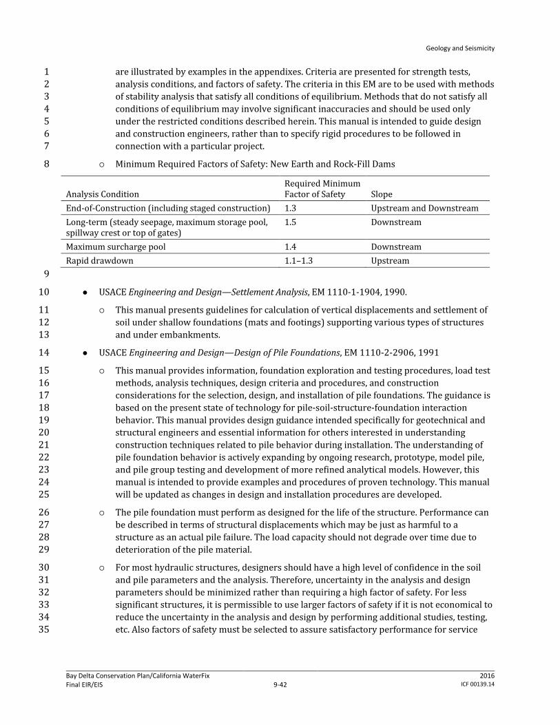
Geology and Seismicity
Bay Delta Conservation Plan/California WaterFix Final EIR/EIS
Administrative Final 9-42
2016 ICF 00139.14
are illustrated by examples in the appendixes. Criteria are presented for strength tests, 1 analysis conditions, and factors of safety. The criteria in this EM are to be used with methods 2 of stability analysis that satisfy all conditions of equilibrium. Methods that do not satisfy all 3 conditions of equilibrium may involve significant inaccuracies and should be used only 4 under the restricted conditions described herein. This manual is intended to guide design 5 and construction engineers, rather than to specify rigid procedures to be followed in 6 connection with a particular project. 7
Minimum Required Factors of Safety: New Earth and Rock-Fill Dams 8
Analysis Condition Required Minimum Factor of Safety Slope
End-of-Construction (including staged construction) 1.3 Upstream and Downstream Long-term (steady seepage, maximum storage pool, spillway crest or top of gates)
1.5 Downstream
Maximum surcharge pool 1.4 Downstream Rapid drawdown 1.1–1.3 Upstream 9
USACE Engineering and Design—Settlement Analysis, EM 1110-1-1904, 1990. 10
This manual presents guidelines for calculation of vertical displacements and settlement of 11 soil under shallow foundations (mats and footings) supporting various types of structures 12 and under embankments. 13
USACE Engineering and Design—Design of Pile Foundations, EM 1110-2-2906, 1991 14
This manual provides information, foundation exploration and testing procedures, load test 15 methods, analysis techniques, design criteria and procedures, and construction 16 considerations for the selection, design, and installation of pile foundations. The guidance is 17 based on the present state of technology for pile-soil-structure-foundation interaction 18 behavior. This manual provides design guidance intended specifically for geotechnical and 19 structural engineers and essential information for others interested in understanding 20 construction techniques related to pile behavior during installation. The understanding of 21 pile foundation behavior is actively expanding by ongoing research, prototype, model pile, 22 and pile group testing and development of more refined analytical models. However, this 23 manual is intended to provide examples and procedures of proven technology. This manual 24 will be updated as changes in design and installation procedures are developed. 25
The pile foundation must perform as designed for the life of the structure. Performance can 26 be described in terms of structural displacements which may be just as harmful to a 27 structure as an actual pile failure. The load capacity should not degrade over time due to 28 deterioration of the pile material. 29
For most hydraulic structures, designers should have a high level of confidence in the soil 30 and pile parameters and the analysis. Therefore, uncertainty in the analysis and design 31 parameters should be minimized rather than requiring a high factor of safety. For less 32 significant structures, it is permissible to use larger factors of safety if it is not economical to 33 reduce the uncertainty in the analysis and design by performing additional studies, testing, 34 etc. Also factors of safety must be selected to assure satisfactory performance for service 35
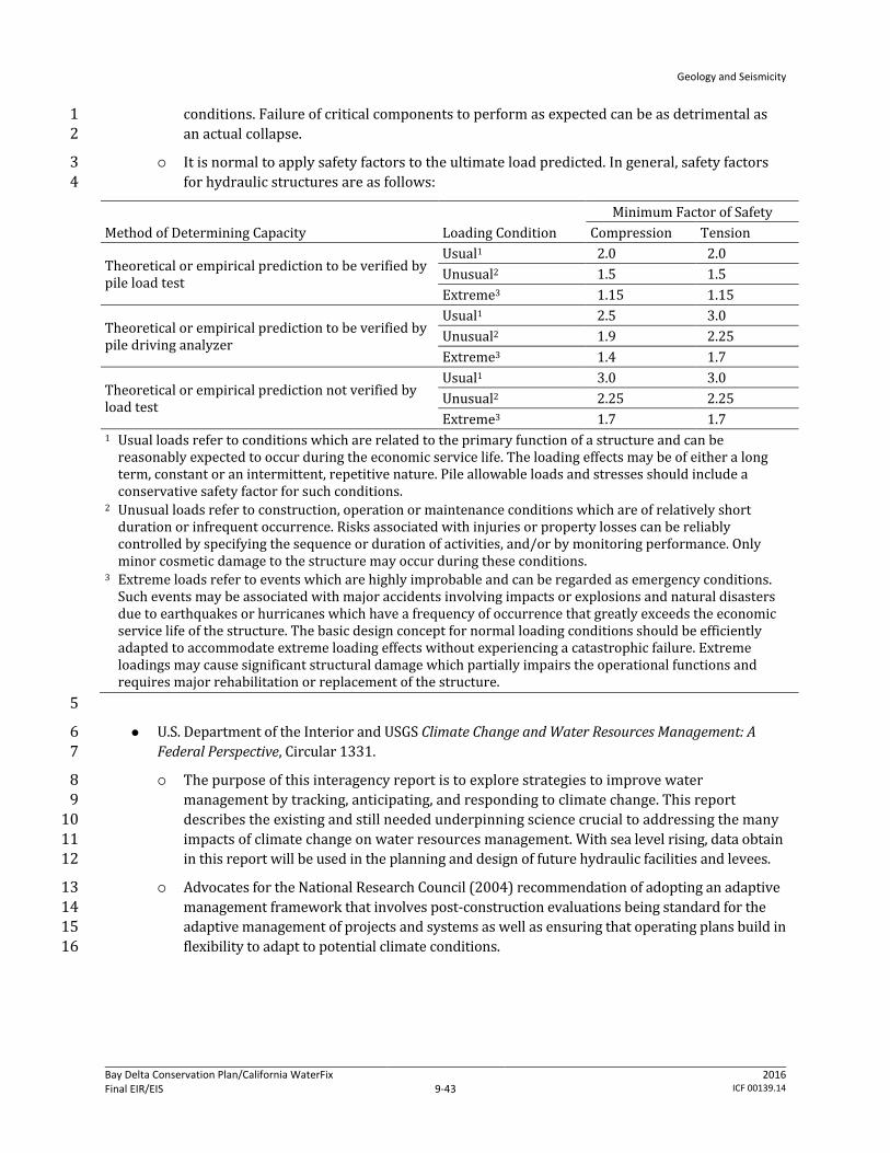
Geology and Seismicity
Bay Delta Conservation Plan/California WaterFix Final EIR/EIS
Administrative Final 9-43
2016 ICF 00139.14
conditions. Failure of critical components to perform as expected can be as detrimental as 1 an actual collapse. 2
It is normal to apply safety factors to the ultimate load predicted. In general, safety factors 3 for hydraulic structures are as follows: 4
Method of Determining Capacity Loading Condition Minimum Factor of Safety
Compression Tension
Theoretical or empirical prediction to be verified by pile load test
Usual1 2.0 2.0 Unusual2 1.5 1.5 Extreme3 1.15 1.15
Theoretical or empirical prediction to be verified by pile driving analyzer
Usual1 2.5 3.0 Unusual2 1.9 2.25 Extreme3 1.4 1.7
Theoretical or empirical prediction not verified by load test
Usual1 3.0 3.0 Unusual2 2.25 2.25 Extreme3 1.7 1.7
1 Usual loads refer to conditions which are related to the primary function of a structure and can be reasonably expected to occur during the economic service life. The loading effects may be of either a long term, constant or an intermittent, repetitive nature. Pile allowable loads and stresses should include a conservative safety factor for such conditions.
2 Unusual loads refer to construction, operation or maintenance conditions which are of relatively short duration or infrequent occurrence. Risks associated with injuries or property losses can be reliably controlled by specifying the sequence or duration of activities, and/or by monitoring performance. Only minor cosmetic damage to the structure may occur during these conditions.
3 Extreme loads refer to events which are highly improbable and can be regarded as emergency conditions. Such events may be associated with major accidents involving impacts or explosions and natural disasters due to earthquakes or hurricanes which have a frequency of occurrence that greatly exceeds the economic service life of the structure. The basic design concept for normal loading conditions should be efficiently adapted to accommodate extreme loading effects without experiencing a catastrophic failure. Extreme loadings may cause significant structural damage which partially impairs the operational functions and requires major rehabilitation or replacement of the structure.
5
U.S. Department of the Interior and USGS Climate Change and Water Resources Management: A 6 Federal Perspective, Circular 1331. 7
The purpose of this interagency report is to explore strategies to improve water 8 management by tracking, anticipating, and responding to climate change. This report 9 describes the existing and still needed underpinning science crucial to addressing the many 10 impacts of climate change on water resources management. With sea level rising, data obtain 11 in this report will be used in the planning and design of future hydraulic facilities and levees. 12
Advocates for the National Research Council (2004) recommendation of adopting an adaptive 13 management framework that involves post-construction evaluations being standard for the 14 adaptive management of projects and systems as well as ensuring that operating plans build in 15 flexibility to adapt to potential climate conditions. 16

Geology and Seismicity
Bay Delta Conservation Plan/California WaterFix Final EIR/EIS
Administrative Final 9-44
2016 ICF 00139.14
9.3 Environmental Consequences 1
This section describes the potential effects that could result from project construction, operation 2 and maintenance, and restoration due to geologic and seismic-related conditions and hazards. The 3 types of effects that are evaluated include the following. 4
Exposure of people or structures to potential substantial adverse effects, including the risk of 5 loss of property, personal injury, or death, involving the below. 6
Rupture of a known earthquake fault, as delineated on the most recent AP Earthquake Fault 7 Zoning Map issued by the state geologist for the area or based on other substantial evidence 8 of a known fault. 9
Strong seismic ground shaking. 10
Liquefaction. 11
Seismic-related ground failure. 12
Slope instability. 13
Soft, loose, and compressible soils. 14
Seiche, tsunami, or mudflow. 15
Location relative to geologic units or soils that are unstable or that would become unstable as a 16 result of the project and potentially result in on- or off-site landslide, lateral spreading, 17 subsidence, liquefaction, or collapse. 18
Geologic and seismic effects on structures and construction activities associated with the proposed 19 project would be restricted to the Plan Area, but the Plan Area could be affected by seismic 20 conditions well outside the Plan Area. Because all conveyance and restoration activities related to 21 the project would occur within the Plan Area, geologic and seismic conditions Upstream of the Delta 22 and within the SWP and CVP Export Service Areas would not be affected by construction, operation, 23 maintenance, or restoration activities. Therefore, this section does not evaluate effects in those 24 geographic areas. 25
Potential adverse effects associated with near-surface soils, including erosion; subsidence caused by 26 oxidation of organic matter; and expansive, corrosive, and compressible soils, are assessed in 27 Chapter 10, Soils. Further discussion of levee stability and flooding is provided in Chapter 6, Surface 28 Water. Potential effects of irrigation-induced salt loading to soils are addressed in Chapter 8, Water 29 Quality, and Chapter 14, Agricultural Resources. Potential effects on mineral resources are fully 30 discussed in Chapter 26, Mineral Resources. 31
9.3.1 Methods for Analysis 32
This section describes the methods used to evaluate the potential for geologic and seismic hazards 33 to affect the constructed and operational elements of the alternatives and the potential for the 34 elements of the alternatives to increase human health risk and loss of property or other associated 35 risks. Some of these effects would be temporary, associated with construction activities within the 36 geographic footprint of disturbance of new facilities in the Plan Area. Other effects would be more 37 regional in nature, associated with the presence of new structures and water operations throughout 38 the Plan Area. Lands outside of the Plan Area are not being considered because there are no 39

Geology and Seismicity
Bay Delta Conservation Plan/California WaterFix Final EIR/EIS
Administrative Final 9-45
2016 ICF 00139.14
structures being proposed and because changed operations upstream and within the water user 1 service areas do not increase geologic or seismic hazards in those areas. Both quantitative and 2 qualitative methods were used to evaluate these effects, depending on the availability of data. 3 Conservation and restoration activities were evaluated on a programmatic level using qualitative 4 methods to estimate potential effects. 5
The impact analysis for geology and seismicity was performed primarily using information on soils 6 and stratigraphy, area topography, subsurface conditions, and potential earthquake hazards 7 developed for the CERs and Geotechnical Data Reports, as listed below. 8
Conceptual Engineering Report—Isolated Conveyance Facility—All Tunnel Option (California 9 Department of Water Resources 2010a). 10
Conceptual Engineering Report—Isolated Conveyance Facility—Pipeline/Tunnel Option—11 Addendum (California Department of Water Resources 2010b). 12
Conceptual Engineering Report—Isolated Conveyance Facility—East Option (California 13 Department of Water Resources 2009a). 14
Conceptual Engineering Report—Isolated Conveyance Facility—East Option—Addendum 15 (California Department of Water Resources 2010c). 16
Conceptual Engineering Report—Isolated Conveyance Facility—West Option (California 17 Department of Water Resources 2009b). 18
Conceptual Engineering Report—Isolated Conveyance Facility—West Option—Addendum 19 (California Department of Water Resources 2010d). 20
Conceptual Engineering Report—Dual Conveyance Facility Modified Pipeline/Tunnel Option —21 Clifton Court Forebay Pumping Plant (MPTO/CCO), Volume 1. (California Department of Water 22 Resources 2015) 23
Option Description Report—Separate Corridors Option (California Department of Water 24 Resources 2010e). 25
Draft Phase II Geotechnical Investigation—Geotechnical Data Report—Pipeline/Tunnel Option 26 (California Department of Water Resources 2011). 27
Draft Phase I Geotechnical Investigation—Geotechnical Data Report—Isolated Conveyance Facility 28 West (California Department of Water Resources 2010g). 29
Draft Phase I Geotechnical Investigation—Geotechnical Data Report—Isolated Conveyance Facility 30 East (California Department of Water Resources 2010h). 31
Other study results and applicable maps and information published by various regulatory agencies, 32 researchers and consultants were also used (e.g., California Department of Water Resources 1992; 33 CALFED Bay-Delta Program 2000; California Department of Water Resources and California 34 Department of Fish and Wildlife 2008, Shlemon and Begg 1975; Fugro Consultants 2011). The 35 emphasis in the impact analysis has been to identify where the existing data suggest that geologic or 36 seismic conditions pose a potentially serious threat to structural integrity. The analysis determines 37 whether these conditions and associated risk can be reduced to less than significant by conformance 38 with existing codes, standards and the application of accepted, proven construction engineering 39 practices. A range of specific design and construction approaches are normally available to address a 40 specific circumstance. For example, the potential for liquefaction to affect structural integrity could 41

Geology and Seismicity
Bay Delta Conservation Plan/California WaterFix Final EIR/EIS
Administrative Final 9-46
2016 ICF 00139.14
be controlled using a range of engineering approaches, such as by removal and replacement of the 1 liquefiable soil with engineered fill and construction of the structure on pilings founded on non-2 liquefiable material. Specific control measures have not been developed for all site conditions at this 3 point in the BDCP/California WaterFix planning process. Regardless of the control method used, the 4 same stability criteria must be met to conform to code and standards requirements. Design solutions 5 would be guided by relevant building codes and state and federal standards for constructing 6 foundations, bridges, tunnels, earthworks, and all other project facilities, listed in Section 9.2.2.6, 7 Regulatory Design Codes and Standards for Project Structures. This evaluation process is described in 8 more detail below in Section 9.3.1.1. Methodologies for evaluating specific geologic and seismic 9 hazards are further defined in Section 9.3.1.3, Evaluation of Operations. 10
Indirect environmental effects related to levee failure and breaches that could result in flooding are 11 described in Chapter 6, Surface Water. Other resources that may be affected by the geologic and 12 seismic conditions of the Plan Area are addressed in Chapter 7, Groundwater, and Chapter 10, Soils. 13 Potential effects on mineral resources are discussed in Chapter 26, Mineral Resources. 14
9.3.1.1 Process and Methods of Review for Geologic and Seismic 15 Hazards 16
This section describes the sequence of planning, evaluation, review and design activities that 17 identify geologic and seismic hazards and establish approaches to avoiding or minimizing those 18 hazards. This is the process being implemented to avoid significant hazards to structures and human 19 health associated with the project. The description of the process and methods is intended to make 20 it clear how site-specific hazard conditions are identified and fully addressed through data 21 collection, analysis and conformance with existing design and construction requirements. 22
As the proposed project has been developed by DWR in anticipation of agency and public review 23 through the CEQA/NEPA processes, the agency has developed geologic and geotechnical information 24 for all of the conveyance alignment alternatives. This information has been developed under the 25 supervision of professional engineers and documented in the geotechnical data reports prepared by 26 DWR for the project. As is appropriate for a project of this scale, these documents show project and 27 alternative feasibility by identifying site geotechnical conditions along with associated constraints 28 and opportunities. The geology and seismicity analyses in this chapter include review of the 29 geotechnical data reports and other existing reports and data to determine whether significant risks 30 might occur from implementing the proposed project. 31
Seismic and geologic hazards are determined to be adverse under NEPA or significant under CEQA if 32 their related effects pose a substantial risk of damage to structures or pose a substantial human 33 health threat. The criteria used to evaluate significance do not require the elimination of the 34 potential for structural damage from the site’s geologic and seismic conditions. Rather, the criteria 35 require evaluation of whether site conditions can be overcome through engineering design solutions 36 that reduce the substantial risk to people and structures. The codes and design standards referred to 37 above ensure that buildings and structures are designed and constructed so that, while they may 38 sustain damage during a major earthquake, the substantial risk of loss of property, personal injury 39 or death due to structure failure or collapse is reduced. The CEQA/NEPA evaluation considers 40 whether conformance with existing codes and standards, and application of accepted, proven 41 construction engineering practices, would reduce the substantial risk to people and structures. 42

Geology and Seismicity
Bay Delta Conservation Plan/California WaterFix Final EIR/EIS
Administrative Final 9-47
2016 ICF 00139.14
Configuration of the proposed action alternatives will be determined when the CEQA/NEPA review 1 is completed. Development of final-level design and inclusion of more detailed information would 2 not be likely to substantially modify any CEQA/NEPA conclusions. After CEQA/NEPA document 3 certification, the final design of structures will be developed; this will require additional subsurface 4 geotechnical investigations to identify very localized conditions that must be reflected in the final 5 engineering design. DWR has developed a Draft Geotechnical Exploration Plan (Phase 2) for the 6 Alternative 4 conveyance alignment (MPTO), which will support the final engineering design. The 7 Geotechnical Exploration Plan provides additional details regarding the rationale, investigation 8 methods and locations, and criteria for obtaining subsurface soil information and laboratory test 9 data (California Department of Water Resources 2014). The proposed exploration is designed as a 10 two-part program (Phases 2a and 2b) to collect geotechnical data. The two-part program will allow 11 refinement of the second part of the program (Phase 2b) to respond to findings from the first part 12 (Phase 2a). The proposed subsurface exploration will focus on geotechnical considerations of the 13 following aspects of water conveyance facility development: engineering considerations, 14 construction-related considerations, permitting and regulatory requirements, and seismic 15 characterization considerations. These geotechnical investigation will characterize, log, and test 16 soils and bedrock at selected construction sites to further refine anticipated site responses to 17 seismic activity and the various loads created by structures. They will also refine the design 18 parameters that must be met. The geotechnical investigations and their recommendations will be 19 presented in a report that is reviewed and approved by a California-registered civil engineer or a 20 certified engineering geologist who is competent in the field of seismic hazard evaluation and 21 mitigation. The requirements for evaluating seismic hazards other than surface fault rupture and for 22 recommending mitigation measures that the California-registered civil engineer or certified 23 engineering geologist or geologist must follow are specified in Guidelines for Evaluating and 24 Mitigating Seismic Hazards in California (California Geological Survey 2008). The project proponents 25 have made an environmental commitment that final design of all constructed components will meet 26 the standards listed in Section 9.2.2.6, Regulatory Design Codes and Standards for Project Structures 27 and contained in Appendix 3B, Environmental Commitments, AMMs, and CMs. The constructed 28 components may include canals, tunnels, intake structures, pipelines, transmission lines, levees, 29 temporary and permanent access roads, bridges, borrow areas, and spoils storage sites. 30
Based on the final geotechnical reports and code and standards requirements, the final design of 31 structures will be developed by the aforementioned California-registered civil engineer or 32 California-certified engineering geologist with participation and review by the project proponents, 33 and in some cases county building departments, to ensure that design standards are met. The design 34 and construction specifications will then be incorporated into a construction contract for 35 implementation and required to be implemented. During project construction, new or unexpected 36 conditions may be found that are different than shown in the detailed, site-specific geotechnical 37 report that guides the final design. Under these circumstances, the new condition will be evaluated 38 and an appropriate method to meet the design specification will be determined by the project’s 39 California-registered civil engineer or California-certified engineering geologist and approved by the 40 project proponents. Although new or unexpected conditions may be found, the design standards will 41 not change. 42
9.3.1.2 Evaluation of Construction Activities 43
Construction activities for the water conveyance facilities as they are currently defined, were 44 evaluated on a project level for potential effects relating to existing geologic hazards and to conform 45

Geology and Seismicity
Bay Delta Conservation Plan/California WaterFix Final EIR/EIS
Administrative Final 9-48
2016 ICF 00139.14
to federal and state regulations and guidance pertaining to geologic hazard mitigation. Construction 1 activities in the ROAs were evaluated on a programmatic level for potential effects relating to 2 existing geologic hazards. These effects will need to be discussed in greater detail in subsequent 3 project-level environmental documentation after specific restoration activities are finalized. 4
Geologic and seismic analysis of construction-related effects included these methodologies and 5 approaches. 6
Review of conveyance alternatives and construction methods and sequences. The available 7 design drawings, reports, and memoranda were reviewed, including construction methods, 8 borrow areas, and dewatering systems. 9
Review of available site topography and conditions and soil and groundwater data. The 10 available data within the Plan Area, as presented in the CERs and the Geotechnical Data Reports 11 (see list at the beginning of Section 9.3.1), were compiled and reviewed. Available soil boring 12 logs, subsurface cross sections, soil stratigraphy, and groundwater data from the CER were used. 13 Geology and soil maps (from the U.S. Geological Survey and Natural Resources Conservation 14 Service) for the Plan Area were also used, with particular focus on areas where soft, loose, and 15 compressible soils are present. 16
Evaluation of potential effects caused by geologic conditions. Potential effects of 17 construction activities from geologic hazards and the potential for increased risk were 18 evaluated. Engineering design criteria were reviewed and assessed to evaluate how substantial 19 effects were addressed. 20
Surface Fault Rupture 21
Two types of surface fault rupture were addressed: sudden rupture and offset during an earthquake 22 event, and slow offset caused by long-term fault creep in the absence of an earthquake. The potential 23 for near-surface ground disturbance was assessed for blind thrust faults because they are not 24 expected to rupture to the ground surface as a result of fault creep or sudden offset. 25
The methodology for assessing surface fault rupture was based primarily on the available AP Fault 26 Zone Maps. Additional information provided in the CERs and the available published information on 27 fault rupture risks were also used. Areas within the footprints of each alternative located within the 28 AP fault zones or having the potential of experiencing ground ruptures during future earthquakes 29 were identified. For each area having fault rupture potential, the median (50th percentile) and 84th 30 percentile fault offsets during earthquakes were determined using published empirical 31 relationships. The long-term offset attributable to fault creep was also estimated using fault slip rate 32 and time frame considered. 33
Earthquake Ground Shaking 34
For engineering design purposes, ground shaking is commonly quantified by a response spectrum, 35 which is a plot of peak responses (acceleration, velocity, or displacement) of a single-degree-of-36 freedom oscillator of varying natural frequency or period. Peak acceleration response at a period of 37 zero seconds or PGA is also widely used to characterize the level of ground motion. Earthquake 38 ground shaking is influenced by local site topography and soil conditions. Thick deposits of soft soils 39 (such as peaty mud) tend to amplify long-period motions, such as the response at a period of 1.0 40 second. 41

Geology and Seismicity
Bay Delta Conservation Plan/California WaterFix Final EIR/EIS
Administrative Final 9-49
2016 ICF 00139.14
The potential exposure to ground shaking during future earthquakes and the effects to facilities 1 within all Build Alternative footprints was evaluated using the results of the CERs. Specifically, the 2 effects of ground motions predicted for various probabilities of exceedance during the design life of 3 the project were addressed. Seismic study results were interpolated and extrapolated to estimate 4 ground shaking for time periods not presented in the CERs; no new seismic ground motion 5 calculations were performed. Comparisons to previous studies were also made to validate the 6 ground motion estimates. 7
Liquefaction 8
Regional variations in the seismic vulnerability of existing levees in the Delta and Suisun Marsh to 9 failure caused by seismic shaking alone and by seismically induced liquefaction were assessed based 10 on two Delta Risk Management Strategy reports (California Department of Water Resources 2008a, 11 b). See the Liquefaction section under Section 9.1.1.4, Geological and Seismic Hazards, for a more 12 detailed discussion. 13
Liquefaction hazard for specific conveyance facility locations was assessed using the available soil 14 data from the CERs. The assessment was performed primarily through correlations with basic soil 15 characteristics (soil type, water content, depositional environment, and age). For areas where 16 adequate soil engineering data were not available, additional analyses were performed, including 17 assessments based on SPT sampler penetration blow-counts (SPT blow-counts), Cone Penetration 18 Test (CPT) measurements, and shear-wave velocity of the soil. The liquefaction analysis (for areas 19 where adequate soil engineering data were available) was performed for earthquake ground 20 motions with return periods of 475 years and 975 years, corresponding to 10% and 5% 21 probabilities of being exceeded in 50 years, respectively. The controlling earthquake magnitudes 22 were determined from the results of the seismic study (California Department of Water Resources 23 2007a) and/or the U.S. Geological Survey National Seismic Hazard Mapping Program. 24
Ground Failure and Seismic-Induced Soil Instability 25
Compaction and Settlement 26
Seismic-induced ground compaction and settlements are caused by the rearrangement of soil 27 particles during an earthquake. Soil experiencing liquefaction tends to produce an increased amount 28 of compaction and settlement. Excessive ground compaction may lead to large differential and/or 29 total settlement and cause damage to facilities, lifelines, and other utilities. 30
A study of the characteristics of the soil found along the footprint of the proposed project was 31 performed to give a qualitative assessment as to the potential for seismic-induced soil compaction 32 and settlement. 33
Loss of Bearing Capacity 34
Loss of soil bearing capacity results mainly from significant reduction in soil effective stresses 35 during an earthquake. In the case of liquefaction, soil effective stresses drop to almost zero, and soil 36 strength reaches its residual value (soil residual strength). When soil strength is not sufficient to 37 maintain stability, large deformation occurs, leading to foundation failure and excessive soil 38 settlements and lateral movements. 39

Geology and Seismicity
Bay Delta Conservation Plan/California WaterFix Final EIR/EIS
Administrative Final 9-50
2016 ICF 00139.14
A study of the type of the soil found along the footprint of the proposed project was performed to 1 give a qualitative assessment as to the potential for substantial loss of bearing capacity during 2 earthquakes. 3
Lateral Spreading 4
Lateral spreading typically occurs when the soil underlying an earth slope or near a free face 5 liquefies during an earthquake. It can occur on gently sloping ground and extend large distances 6 from the slope’s open face. 7
A study of the characteristics of the soil/sediment and site topography found along the footprint of 8 the proposed project was performed to give a qualitative assessment as to the potential for soil 9 lateral movement. 10
Increased Lateral Soil Pressure 11
When soil liquefies, it behaves as a heavy liquid and may induce increased soil lateral pressure to 12 walls or buried pipes and tunnels. The increased soil lateral pressure was estimated using liquefied 13 soil unit weight, which is roughly twice the unit weight of water. Even when a soil does not liquefy 14 during a seismic event, lateral earth pressures will increase mainly because of inertia earthquake 15 forces. 16
Buoyancy 17
As soil liquefies, it causes an increase in buoyancy pressure on buried structures or parts of facilities 18 below the ground, similar to increased soil lateral pressure. The buoyancy forces were estimated 19 using liquefied soil unit weight. 20
Slope Instability 21
Slope instability (e.g., landslides, soil creep, and debris flow) can occur as a result of gravity loads or 22 in combination with earthquake loads. Analysis focused on areas where past instability had 23 occurred or where water saturates slope materials to estimate the potential for slope instability. In 24 areas where facilities may be built, new cut-and-fill slopes were identified and evaluated for 25 stability. 26
A qualitative slope stability evaluation was performed based on slope inclination, soil type, and 27 groundwater conditions. For areas where adequate soil and site data were available, slope stability 28 was evaluated using a two-dimensional slope model and the limit-equilibrium method. Impact 29 assessments for the existing levees are described in Chapter 6, Surface Water. 30
Soft, Loose, and Compressible Soils 31
The team used both geographic information system (GIS) data and available geology and soil maps 32 to identify areas with soft, loose, and compressible soil within the footprints of each of the 33 alternatives. The thicknesses of these soils were estimated using available geotechnical exploration 34 data. 35
Seismic-Induced Seiche and Tsunami 36
The basis for determining the hazard for seismically induced seiche and tsunami is discussed 37 Section 9.1.1.3, Regional and Local Seismicity. 38
Geology and Seismicity
Bay Delta Conservation Plan/California WaterFix Final EIR/EIS
Administrative Final 9-51
2016 ICF 00139.14
9.3.1.3 Evaluation of Operations 1
The potential for operation of the proposed facilities to directly or indirectly affect geologic hazards 2 or increase risks associated with geologic hazards was evaluated. The potential for adverse effects 3 caused by operation of the conveyance facilities was identified, and maintenance plans to address 4 the effects were evaluated. 5
Analysis methodologies and approaches for operation-related effects include review of the facilities 6 and their operations and evaluation of effects (including erosion, soil/slope instability, groundwater 7 fluctuation, and facility failures) caused by operation. 8
9.3.2 Determination of Effects 9
The effects of the action alternatives on geologic and seismic risks may result from both 10 construction and operation of project features. This effects analysis assumes that an action 11 alternative would result in an adverse effect (under NEPA) or a significant impact (under CEQA) if it 12 exposes people or structures to a substantially greater potential for loss of property, personal injury 13 or death from the following effects. 14
Earthquake fault rupture. 15
Strong seismic ground shaking. 16
Liquefaction. 17
Seismic-related ground failure. 18
Slope instability (landslides). 19
Soft, loose and compressible soils. 20
Seiche, tsunami, or mudflow. 21
For the purposes of this analysis, “substantially greater potential for loss, injury or death” is defined 22 as any circumstance in which construction or operational activities have an increased likelihood of 23 resulting in direct property loss, personal injury or death of individuals. Potential effects caused by 24 subsidence, expansive and corrosive soils, and other such hazards are described in Chapter 10, Soils. 25 Potential flooding effects are described in Chapter 6, Surface Water. 26
9.3.2.1 Compatibility with Plans and Policies 27
Constructing the proposed water conveyance facility and implementing CM2–CM21, or 28 Environmental Commitments 3, 4, 6-12, 15 and 16 under the non-HCP alternatives, could potentially 29 result in incompatibilities with plans and policies related to geologic/seismic hazards. Section 9.2, 30 Regulatory Setting, provides an overview of federal, state, regional and agency-specific plans and 31 policies applicable to seismic safety and levee stability. This section summarizes ways in which the 32 proposed project is compatible or incompatible with those plans and policies. Potential 33 incompatibilities with local plans or policies do not necessarily translate into adverse environmental 34 effects under NEPA or CEQA. Even where an incompatibility “on paper” exists, it does not by itself 35 constitute an adverse physical effect on the environment, but rather may indicate the potential for a 36 proposed activity to have a physical effect on the environment. The relationship between plans, 37 policies, and regulations and impacts on the physical environment is discussed in Chapter 13, Land 38 Use, Section 13.2.3. 39

Geology and Seismicity
Bay Delta Conservation Plan/California WaterFix Final EIR/EIS
Administrative Final 9-52
2016 ICF 00139.14
Government Code Section 65302(g)(1) requires a seismic safety and safety element in all city and 1 county general plans. The effect of this section is to require cities and counties to take seismic and 2 safety hazards into account in their planning programs. The basic objective is to reduce loss of life, 3 injuries, damage to property, and economic and social dislocations resulting from future 4 earthquakes or other natural disasters. Generally, these local plans require mitigation of potential 5 impacts of geologic hazards through development and building review, maintaining compatible land 6 uses and appropriate construction techniques. Additionally, development projects are to conform to 7 state seismic and building standards in the design and siting of critical facilities. Implementing a 8 selected alternative could require construction of structures on or near blind faults. However, as 9 discussed below under Impacts GEO-1 through GEO-16, construction and operation of the 10 alternatives are not expected to create any additional seismic or geologic risk to lives or property. 11 The project proponents would implement an environmental commitment to conform to relevant 12 state codes and standards to avoid creating any additional impacts from geologic/seismic hazards. 13 Additionally, prior to construction, a California-registered civil engineer or California-certified 14 engineering geologist would conduct site-specific evaluation for potential hazards and recommend 15 measures in a geotechnical report to address hazards such as ground settlement or collapse from 16 dewatering and potential liquefaction. These environmental commitments ensure the proposed 17 project is compatible with the mission and goals of relevant general plans. 18
The Delta Plan, discussed generally in Section 9.2.2.1, has adopted policy RR P1, Prioritization of 19 Statement Investments in Delta Levees and Risk Reduction. This policy covers any proposed action 20 that involves discretionary State investments in Delta flood risk management, including levee 21 operations, maintenance, and improvements, such as the proposed project. The Delta Stewardship 22 Council, in consultation with DWR, the Central Valley Flood Protection Board, and the California 23 Water Commission, developed priorities for interim funding that include emergency preparedness, 24 response, and recovery, as well as Delta levees funding. This policy prioritizes localized flood 25 protection for existing urban areas by providing 200-year flood protection; protecting water quality 26 and water supply conveyance in the Delta, especially levees that protect freshwater aqueducts and 27 the primary channels that carry fresh water through the Delta; and protecting existing and 28 providing for a net increase in channel-margin habitat. All of the levee alterations required by the 29 project alternatives meet this description. Therefore, the alternatives are compatible with the Delta 30 Plan policies relevant to this resource area. 31
9.3.3 Effects and Mitigation Approaches 32
9.3.3.1 No Action Alternative 33
The No Action Alternative is the future condition at 2060 that would occur if none of the action 34 alternatives were approved and if no change from current management direction or the level of 35 management intensity of existing programs by federal, state, and local agencies occurred. The No 36 Action Alternative considers changes in risk from geology and seismicity that would take place as a 37 result of the continuation of existing plans, policies, and operations, as described in Chapter 3, 38 Description of Alternatives. The No Action Alternative includes projects and programs with defined 39 management or operational plans, including facilities under construction as of February 13, 2009, 40 because those actions would be consistent with the continuation of existing management direction 41 or level of management for plans, policies, and operations by the project proponents and other 42 agencies. The No Action Alternative assumptions also include projects and programs that are 43
Geology and Seismicity
Bay Delta Conservation Plan/California WaterFix Final EIR/EIS
Administrative Final 9-53
2016 ICF 00139.14
permitted or are assumed to be constructed by 2060. The No Action Alternative would result in the 1 following effects on geology and seismicity. 2
Earthquake-Induced Ground Shaking, Liquefaction, and Slope Instability 3
Under the No Action Alternative, it is anticipated that the current hazard resulting from earthquake-4 induced ground shaking from regional and local faults would persist. This would continue to present 5 a risk of levee failure and subsequent flooding of Delta islands, with a concomitant influx of seawater 6 into the Delta, thereby adversely affecting water quality and water supply. The effects of flooding of 7 Delta islands and consequently on water quality and supply are described in Appendix 3E, Potential 8 Seismicity and Climate Change Risks to SWP/CVP Water Supplies and Chapter 6, Surface Water. 9
It is also anticipated that the current hazard of earthquake-induced liquefaction triggered by 10 regional and local faults would persist. Liquefaction would continue to present a risk of levee failure 11 and subsequent flooding of Delta islands, with concomitant water quality and water supply effects 12 from seawater intrusion as described in Appendix 3E, Potential Seismicity and Climate Change Risks 13 to SWP/CVP Water Supplies. 14
The current hazard of earthquake-induced slope instability (e.g., levee failure) triggered by regional 15 and local faults would continue under the No Action Alternative. Slope instability associated with 16 non-engineered levees would continue to present a risk of levee failure and subsequent flooding of 17 Delta islands. Ongoing and reasonably foreseeable future projects in parts of the Delta are expected 18 to upgrade the levees to a “flood-safe” condition under the 100-year return flood elevation. 19 However, these projects would provide very little levee foundation strengthening and 20 improvements directed at improving the stability of the levees to better withstand ground shaking, 21 liquefaction, and slope instability. 22
Tsunami and Seiche 23
Under the No Action Alternative, it is anticipated that the current hazard resulting from tsunami and 24 seismically induced seiche on Delta and Suisun Marsh levees would continue. As reported above, the 25 hazard of a substantial tsunami affecting the Delta and the Suisun Marsh appears to be minor 26 because of their distance from the Pacific Ocean and the attenuating effect of San Francisco and 27 Suisun bays. With respect to the hazard of a seiche, the existing water bodies in the Delta and Suisun 28 Marsh tend to be wide and shallow. This geometry and distance to seismic sources generally are not 29 conducive to the occurrence of a substantial seismically induced seiche, as described in Section 30 9.1.1.3, Regional and Local Seismicity. However, because of its proximity to the potentially active 31 West Tracy fault, there is a potential hazard for a seiche to occur in the Clifton Court Forebay (Fugro 32 Consultants 2011). 33
Ongoing Plans, Policies, and Programs 34
The programs, plans, and projects included under the No Action Alternative are summarized in 35 Table 9-13, along with their anticipated effects on geology and seismicity. Although not specifically 36 directed at mitigating potential damage to levees caused by a tsunami and seiche, the ongoing and 37 reasonably foreseeable future projects directed to upgrade levees to a “flood-safe” condition under 38 the 100-year return flood elevation or projects involving other similar levee improvements 39 identified in Table 9-13 below may provide some benefit to withstanding the potential effect of a 40 tsunami and seiche. 41

Geology and Seismicity
Bay Delta Conservation Plan/California WaterFix Final EIR/EIS
Administrative Final 9-54
2016 ICF 00139.14
In total, the plans and programs would result in a beneficial effect on an undetermined extent of 1 levees in the Delta. Under the No Action Alternative, these plans, policies, and programs would be 2 deemed to have an indirect and beneficial effect upon the potential hazard of tsunami and seiche in 3 the Delta due to improvements in levee infrastructure as a part of implementation of these projects 4 or programs. 5
Climate Change and Catastrophic Seismic Risks 6
The Delta and vicinity is within a highly active seismic area, with a generally high potential for major 7 future earthquake events along nearby and/or regional faults, and with the probability for such 8 events increasing over time. Based on the location, extent and non-engineered nature of many 9 existing levee structures in the Delta area, the potential for significant damage to, or failure of, these 10 structures during a major local seismic event is generally moderate to high. In the instance of a large 11 seismic event, levees constructed on liquefiable foundations are expected to experience large 12 deformations (in excess of 10 feet) under a moderate to large earthquake in the region. There would 13 potentially be loss, injury or death resulting from ground rupture, ground shaking and liquefaction, 14 (See Appendix 3E, Potential Seismic and Climate Change Risks to SWP/CVP Water Supplies, for more 15 detailed discussion). 16
CEQA Conclusion: In total, the plans and programs would result in a beneficial effect on an 17 undetermined extent of levees in the Delta. Under the No Action Alternative, these plans, policies, 18 and programs would be deemed to have an indirect and beneficial effect upon the potential hazard 19 of tsunami and seiche in the Delta. These plans and programs, however, would not decrease the 20 risks associated with climate change or a catastrophic seismic event, as discussed above and more 21 thoroughly in Appendix 3E, Seismic and Climate Change Risks to SWP/CVP Water Supplies. Given that 22 construction and operation of any new water facilities and habitat restoration would be undertaken 23 following appropriate state codes and standards, there would be no impact of the No Action 24 Alternative related to geology and seismicity (i.e., Impacts GEO-1 to GEO-15). 25
Table 9-13. Effects on Geology and Seismicity from the Plans, Policies, and Programs for the No Action 26 Alternative 27
Agency Program/Project Status Description of Program/Project Effects on Geology and Seismicity
U.S. Army Corps of Engineers
Delta Dredged Sediment Long-Term Management Strategy
Ongoing Maintaining and improving channel function, levee rehabilitation, and ecosystem restoration.
No direct effect on eliminating risks from earthquakes, groundshaking, liquefaction and slope instability. Indirect effect of improving resistance to tsunami and seiche.
California Department of Water Resources
In-Delta Storage Project
Planning phase
Strengthening of existing levees and construction of embankments inside levees.
No direct effect on eliminating risks from earthquakes, groundshaking, liquefaction and slope instability. Indirect effect of improving resistance to tsunami and seiche.
West Sacramento Area Flood Control Agency and U.S. Army Corps of Engineers
West Sacramento Levee Improvements Program
Planning phase
Improvements to levees protecting West Sacramento to meet local and federal flood protection criteria.
No direct effect on eliminating risks from earthquakes, groundshaking, liquefaction and slope instability. Indirect effect of improving resistance to tsunami and seiche.

Geology and Seismicity
Bay Delta Conservation Plan/California WaterFix Final EIR/EIS
Administrative Final 9-55
2016 ICF 00139.14
Agency Program/Project Status Description of Program/Project Effects on Geology and Seismicity
California Department of Water Resources
Levee Repair-Levee Evaluation Program
Ongoing Repair of state and federal project levees.
No direct effect on eliminating risks from earthquakes, groundshaking, liquefaction and slope instability. Indirect effect of improving resistance to tsunami and seiche.
California Department of Water Resources
Delta Levees Flood Protection Program
Ongoing Levee rehabilitation projects in the Delta.
No direct effect on eliminating risks from earthquakes, groundshaking, liquefaction and slope instability. Indirect effect of improving resistance to tsunami and seiche.
California Department of Water Resources
Central Valley Flood Management Planning Program
Planning phase
Among other management actions, involves levee raising and construction of new levees for flood control purposes.
No direct effect on eliminating risks from earthquakes, groundshaking, liquefaction and slope instability. Indirect effect of improving resistance to tsunami and seiche.
Sacramento Area Flood Control Agency, Central Valley Flood Protection Board, U.S. Army Corps of Engineers
Flood Management Program
Ongoing South Sacramento Streams Project component consists of levee, floodwall, and channel improvements.
No direct effect on eliminating risks from earthquakes, groundshaking, liquefaction and slope instability. Indirect effect of improving resistance to tsunami and seiche.
NMFS/USFWS 2008 and 2009 Biological Opinion
Ongoing The Biological Opinions issued by NMFS and USFWS establish certain RPAs and RPMs to be implemented. Some of the RPAs require habitat restoration which may require changes to existing levees and channel improvements.
No direct effect on eliminating risks from earthquakes, groundshaking, liquefaction and slope instability. Indirect effect of improving resistance to tsunami and seiche.
1
9.3.3.2 Alternative 1A—Dual Conveyance with Pipeline/Tunnel and 2 Intakes 1–5 (15,000 cfs; Operational Scenario A) 3
Impact GEO-1: Loss of Property, Personal Injury, or Death from Structural Failure Resulting 4 from Strong Seismic Shaking of Water Conveyance Features during Construction 5
Earthquakes could be generated from local and regional seismic sources during construction of the 6 Alternative 1A water conveyance facilities. Seismically induced ground shaking could cause collapse 7 of facilities at the construction sites. 8
The potential for experiencing earthquake ground shaking during construction in 2020 (during the 9 project’s near-term implementation stage) was estimated using the results of the seismic study 10 (California Department of Water Resources 2007a). The seismic study also computed seismic 11 ground shaking hazards at six locations in the Delta for 2005, 2050, 2100, and 2200. The results of 12 these analyses show that the ground shakings in the Delta are not sensitive to the elapsed time since 13 the last major earthquake (i.e., the projected shaking hazard results for 2005, 2050, 2100, and 2200 14 are similar). 15

Geology and Seismicity
Bay Delta Conservation Plan/California WaterFix Final EIR/EIS
Administrative Final 9-56
2016 ICF 00139.14
Table 9-14 lists the expected PGA and 1.0-second spectral acceleration (Sa) values in 2020 at 1 selected facility locations along the Alternative 1A alignment. For the construction period, a ground 2 motion return period of 72 years was assumed, corresponding to approximately 50% probability of 3 being exceeded in 50 years. Values were estimated for a stiff soil site, as predicted in the seismic 4 study (California Department of Water Resources 2007a), and for the anticipated soil conditions at 5 the facility locations. No computational modeling was conducted for 2020 in the seismic study, so 6 the ground shaking that was computed for 2005 was used to represent the construction near-term 7 period (i.e., 2020). 8
Table 9-14. Expected Earthquake Ground Motions at Locations of Selected Major Facilities during 9 Construction (2020)—Alternative 1A 10
Major Facilities
72-Year Return Period Ground Motions (during construction)
Peak Ground Acceleration (g) 1.0-Sec Sa (g) Stiff Soila Local Soilb Stiff Soila Local Soilb
Intake Locationsc 0.11 0.14 0.13 0.21 Tunnel Location near Venice Islandd 0.20 0.26 0.22 0.35 Clifton Court Forebay/Byron Tract Forebay 0.18 0.23 0.20 0.32 g = gravity. Sa = second spectral acceleration.
a Stiff soil site, with a Vs100ft value of 1,000 ft/s. b Site-adjusted factors of 1.3 and 1.6 were applied to PGA and 1.0-sec Sa values, respectively (adjustments
from a stiff soil site to a soft soil site). c The results of California Department of Water Resources 2007a for the Sacramento site were used. d The results of California Department of Water Resources 2007a for the Sherman Island site were used.
11
NEPA Effects: The seismic study employed time-dependent seismic source models for several major 12 faults in the region. These models were characterized based on the elapsed times since the last 13 major seismic events on the faults. Therefore, the exposure risks predicted in the seismic study 14 would increase if no major events take place on these faults through 2020. The effect could be 15 substantial because seismically induced ground shaking could cause loss of property or personal 16 injury at the Alternative 1A construction sites (including intake locations, pipelines from intakes to 17 the intermediate forebay, the tunnel, and the Byron Tract Forebay) as a result of collapse of 18 facilities. For example, facilities lying directly on or near active blind faults, such as the concrete 19 batch plant and fuel station on Tyler Island and Byron Tract Forebay for Alternative 1A may have an 20 increased likelihood of loss of property or personal injury at these sites in the event of seismically 21 induced ground shaking. Although these blind thrusts are not expected to rupture to the ground 22 surface under the forebays during earthquake events, they may produce ground or near-ground 23 shear zones, bulging, or both (California Department of Water Resources 2007a). For a map of all 24 permanent facilities and temporary work areas associated with this conveyance alignment, see 25 Figure M3-1 in the Mapbook Volume. 26
However, during construction, all active construction sites would be designed and managed to meet 27 the safety and collapse-prevention requirements of the relevant state codes and standards listed 28 earlier in this chapter and expanded upon in Appendix 3B, Environmental Commitments, AMMs, and 29 CMs, for the above-anticipated seismic loads. In particular, conformance with the following codes 30 and standards would reduce the potential risk for increased likelihood of loss of property or 31
Geology and Seismicity
Bay Delta Conservation Plan/California WaterFix Final EIR/EIS
Administrative Final 9-57
2016 ICF 00139.14
personal injury from structural failure resulting from strong seismic shaking of water conveyance 1 features during construction. 2
DWR Division of Engineering State Water Project—Seismic Loading Criteria Report, September 3 2012. 4
USACE Engineering and Design—Earthquake Design and Evaluation for Civil Works Projects, 5 ER 1110-2-1806, 1995. 6
USACE Engineering and Design—Earthquake Design and Evaluation of Concrete Hydraulic 7 Structures, EM 1110-2-6053, 2007. 8
USACE Engineering and Design—Response Spectra and Seismic Analysis for Concrete Hydraulic 9 Structures, EM 1110-2-6050, 1999. 10
USACE Engineering and Design—Stability Analysis of Concrete Structures, EM 1110-2-2100, 2005. 11
8 CCR Sections 1509 and 3203. 12
Generally, the applicable codes require that facilities be built so that they incur minimal damage in 13 the event of a foreseeable seismic event and that they remain functional following such an event and 14 that the facility is able to perform without catastrophic failure in the event of a maximum design 15 earthquake (the greatest earthquake reasonably expected to be generated by a specific source on 16 the basis of seismological and geological evidence). The safety requirements could include shoring, 17 specified slope angles, excavation depth restrictions for workers, lighting and other similar controls. 18 Conformance with these standards and codes are an environmental commitment of the project (see 19 Appendix 3B, Environmental Commitments, AMMs, and CMs). The worker safety codes and standards 20 specify protective measures that must be taken at construction sites to minimize the risk of injury or 21 death from structural or earth failure (e.g., utilizing personal protective equipment, practicing crane 22 and scaffold safety measures). The relevant codes and standards represent performance standards 23 that must be met by contractors and these measures are subject to monitoring by state and local 24 agencies. The California Department of Industrial Relations Division of Operational Safety and 25 Health (Cal-OSHA) requirements for an IIPP and the terms of the IIPP to protect worker safety are 26 the principal measures that would be enforced at construction sites. Conformance with these health 27 and safety requirements and the application of accepted, proven construction engineering practices 28 would reduce any potential risk such that construction of Alternative 1A would not create an 29 increased likelihood of loss of property, personal injury or death of individuals. Therefore, there 30 would be no adverse effect. 31
CEQA Conclusion: Seismically induced ground shaking that is estimated to occur and the resultant 32 ground motion anticipated at Alternative 1A construction sites, including the intake locations, the 33 tunnel, the pipelines and the forebays, could cause collapse or other failure of project facilities while 34 under construction. For example, facilities lying directly on or near active blind faults, such as the 35 concrete batch plant and fuel station on Tyler Island and the Byron Tract Forebay for Alternative 1A 36 may have an increased likelihood of loss of property or personal injury at these sites in the event of 37 seismically induced ground shaking. However, DWR would conform to Cal-OSHA and other state 38 code requirements, such as shoring, bracing, lighting, excavation depth restrictions, required slope 39 angles, and other measures, to protect worker safety. Conforming to these standards and codes is an 40 environmental commitment of the project (see Appendix 3B, Environmental Commitments, AMMs, 41 and CMs). Conforming to these health and safety requirements and the application of accepted, 42 proven construction engineering practices would reduce any potential risk such that construction of 43

Geology and Seismicity
Bay Delta Conservation Plan/California WaterFix Final EIR/EIS
Administrative Final 9-58
2016 ICF 00139.14
Alternative 1A would not create an increased likelihood of loss of property, personal injury or death 1 of individuals. This risk would be less than significant. No mitigation is required. 2
Impact GEO-2: Loss of Property, Personal Injury, or Death from Settlement or Collapse 3 Caused by Dewatering during Construction of Water Conveyance Features 4
Settlement of excavations could occur as a result of dewatering at Alternative 1A construction sites 5 with shallow groundwater. Soil excavation in areas with shallow or perched groundwater levels 6 would require the pumping of groundwater from excavations to allow for construction of facilities. 7 This can be anticipated at all intake locations (Sites 1–5) and pumping plant sites adjacent to the 8 Sacramento River, where 70% of the dewatering for Alternative 1A would take place. All of the 9 intake locations and adjacent pumping plants for Alternative 1A are located on alluvial floodbasin 10 deposits, alluvial floodplain deposits and natural levee deposits. Similar dewatering may be 11 necessary where intake and forebay pipelines cross waterways and major irrigation canals east of 12 the Sacramento River and north of the proposed intermediate forebay. The conveyance pipeline 13 between Intake 1 and tunnel 1 crosses three canals or ditches. Two of these would be a half mile 14 south of the facility grounds for Intake 1 (or nearer) and the other would be about 0.4 miles north 15 northwest of Scribner Road. The conveyance pipeline between Intake 3 and the intermediate 16 forebay crosses five canals or ditches. Three are 0.6 miles southeast of the facility grounds for Intake 17 3 (or nearer). The other two are both less than 0.25 miles north of the connection with the 18 intermediate forebay. Conveyance pipelines constructed for Intakes 2, 4, and 5 would not be 19 anticipated to intersect with waterways or major irrigation canals. 20
Dewatering can stimulate settlement in excavation and tunneling sites. The settlement could cause 21 the slopes of excavations to fail. This potential effect could be substantial because settlement or 22 collapse during dewatering could result in collapse of excavations at the construction sites. 23
NEPA Effects: The hazard of settlement and subsequent collapse of excavations would be evaluated 24 by assessing site-specific geotechnical and hydrological conditions at intake locations and adjacent 25 pumping plants, as well as where intake and forebay pipelines cross waterways and major irrigation 26 canals. A California-registered civil engineer or California-certified engineering geologist would 27 recommend measures in a geotechnical report to address these hazards, such as seepage cutoff 28 walls and barriers, shoring, grouting of the bottom of the excavation, and strengthening of nearby 29 structures, existing utilities, or buried structures. As described in Section 9.3.1, Methods for Analysis, 30 the measures would conform to applicable design and building codes, guidelines, and standards, 31 such as the California Building Code and USACE‘s Engineering and Design—Structural Design and 32 Evaluation of Outlet Works. See Appendix 3B, Environmental Commitments, AMMs, and CMs. In 33 particular, conformance with the following codes and standards would reduce the potential risk for 34 increased likelihood of loss of property or personal injury from structural failure resulting from 35 settlement or collapse at the construction site caused by dewatering during construction. 36
DWR Division of Flood Management FloodSAFE Urban Levee Design Criteria, May 2012. 37
USACE Engineering and Design—Settlement Analysis, EM 1110-1-1904, 1990. 38
8 CCR Sections 1509 and 3203. 39
Generally, the applicable codes require that facilities be built in such a way that settlement is 40 minimized. DWR would ensure that the geotechnical design recommendations are included in the 41 design of project facilities and construction specifications to minimize the potential effects from 42 settlement and failure of excavations. DWR would also ensure that the design specifications are 43

Geology and Seismicity
Bay Delta Conservation Plan/California WaterFix Final EIR/EIS
Administrative Final 9-59
2016 ICF 00139.14
properly executed during construction. DWR has made an environmental commitment to conform 1 to appropriate code and standard requirements to minimize potential risks (Appendix 3B, 2 Environmental Commitments, AMMs, and CMs). 3
The worker safety codes and standards specify protective measures that must be taken at 4 construction sites to minimize the risk of injury or death from structural or earth failure (e.g., 5 utilizing personal protective equipment, practicing crane and scaffold safety measures). The 6 relevant codes and standards represent performance standards that must be met by contractors and 7 these measures are subject to monitoring by state and local agencies. Cal-OSHA requirements for an 8 IIPP and the terms of the IIPP to protect worker safety are the principal measures that would be 9 enforced at construction sites. 10
Conformance with these health and safety requirements and the application of accepted, proven 11 construction engineering practices would reduce any potential risk such that construction of 12 Alternative 1A would not create an increased likelihood of loss of property, personal injury or death 13 of individuals from settlement or collapse caused by dewatering. Therefore, there would be no 14 adverse effect. 15
CEQA Conclusion: Settlement or failure of excavations during construction could result in 16 settlement or collapse caused by dewatering at construction sites. However, DWR would conform to 17 Cal-OSHA and other state code requirements, such as using seepage cutoff walls, shoring, and other 18 measures, to protect worker safety. DWR or their contractors would also ensure that the design 19 specifications are properly executed during construction. DWR has made an environmental 20 commitment to use the appropriate code and standard requirements to minimize potential risks 21 (see Appendix 3B, Environmental Commitments, AMMs, and CMs). Conforming to these requirements 22 and the application of accepted, proven construction engineering practices would reduce any 23 potential risk such that construction of Alternative 1A would not create an increased likelihood of 24 loss of property, personal injury or death of individuals from settlement or collapse caused by 25 dewatering. This risk would be less than significant. No mitigation is required. 26
Impact GEO-3: Loss of Property, Personal Injury, or Death from Ground Settlement during 27 Construction of Water Conveyance Features 28
Two types of ground settlement could be induced during tunneling operations: large settlement and 29 systematic settlement. Large settlement occurs primarily as a result of over-excavation by the 30 tunneling shield. The over-excavation is caused by failure of the tunnel boring machine to control 31 unexpected or adverse ground conditions (for example, running, raveling, squeezing, and flowing 32 ground) or operator error. Minor settlement occurrences may not be discernible while large 33 settlement can range from interruption of utilities to hindrance of road access. Below the surface, 34 large settlement can lead to the creation of voids and/or sinkholes above the tunnel. This settlement 35 can also affect the ground surface. While this could potentially cause property loss or personal 36 injury above the tunneling operation, instances of large settlement are extremely unlikely to occur 37 due to pre-construction measures and other protective strategies and safety practices during 38 construction. Site-specific geotechnical investigations are needed to design the extent and type of 39 ground improvement that may be required. Ground improvement would be required to facilitate 40 support of tunnel shafts, control groundwater at the locations of the shafts, prevent development of 41 undesired tunnel-induced surface settlements and provide pre-defined zones for tunnel boring 42 machines (TBM) maintenance interventions. The types of ground improvement that would be 43 considered include jet-grouting, permeation or compaction grouting, and ground freezing. The 44
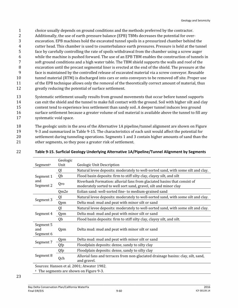
Geology and Seismicity
Bay Delta Conservation Plan/California WaterFix Final EIR/EIS
Administrative Final 9-60
2016 ICF 00139.14
choice usually depends on ground conditions and the methods preferred by the contractor. 1 Additionally, the use of earth pressure balance (EPB) TBMs decreases the potential for over-2 excavation. EPB machines hold the excavated tunnel spoils in a pressurized chamber behind the 3 cutter head. This chamber is used to counterbalance earth pressures. Pressure is held at the tunnel 4 face by carefully controlling the rate of spoils withdrawal from the chamber using a screw auger 5 while the machine is pushed forward. The use of an EPB TBM enables the construction of tunnels in 6 soft ground conditions and a high water table. The TBM shield supports the walls and roof of the 7 excavation until the precast segmental liner is erected at the end of the shield. The pressure at the 8 face is maintained by the controlled release of excavated material via a screw conveyor. Reusable 9 tunnel material (RTM) is discharged into cars or onto conveyors to be removed off site. Proper use 10 of the EPB technique allows only the removal of the theoretically correct amount of material, thus 11 greatly reducing the potential of surface settlement. 12
Systematic settlement usually results from ground movements that occur before tunnel supports 13 can exit the shield and the tunnel to make full contact with the ground. Soil with higher silt and clay 14 content tend to experience less settlement than sandy soil. A deeper tunnel induces less ground 15 surface settlement because a greater volume of soil material is available above the tunnel to fill any 16 systematic void space. 17
The geologic units in the area of the Alternative 1A pipeline/tunnel alignment are shown on Figure 18 9-3 and summarized in Table 9-15. The characteristics of each unit would affect the potential for 19 settlement during tunneling operations. Segments 1 and 3 contain higher amounts of sand than the 20 other segments, so they pose a greater risk of settlement. 21
Table 9-15. Surficial Geology Underlying Alternative 1A/Pipeline/Tunnel Alignment by Segments 22
Segmenta Geologic Unit Geologic Unit Description
Segment 1 and Segment 2
Ql Natural levee deposits: moderately to well-sorted sand, with some silt and clay. Qb Flood basin deposits: firm to stiff silty clay, clayey silt, and silt
Qro Riverbank Formation: alluvial fans from glaciated basins that consist of moderately sorted to well sort sand, gravel, silt and minor clay
Qm2e Eolian sand: well-sorted fine- to medium-grained sand
Segment 3 Ql Natural levee deposits: moderately to well-sorted sand, with some silt and clay. Qpm Delta mud: mud and peat with minor silt or sand
Segment 4 Ql Natural levee deposits: moderately to well-sorted sand, with some silt and clay. Qpm Delta mud: mud and peat with minor silt or sand Qb Flood basin deposits: firm to stiff silty clay, clayey silt, and silt.
Segment 5 and Segment 6
Qpm Delta mud: mud and peat with minor silt or sand
Segment 7 Qpm Delta mud: mud and peat with minor silt or sand Qfp Floodplain deposits: dense, sandy to silty clay
Segment 8 Qfp Floodplain deposits: dense, sandy to silty clay
Qch Alluvial fans and terraces from non-glaciated drainage basins: clay, silt, sand, and gravel.
Sources: Hansen et al. 2001; Atwater 1982. a The segments are shown on Figure 9-3.
23

Geology and Seismicity
Bay Delta Conservation Plan/California WaterFix Final EIR/EIS
Administrative Final 9-61
2016 ICF 00139.14
Operator errors or highly unfavorable/unexpected ground conditions could result in larger 1 settlement. Large ground settlements caused by tunnel construction are almost always the result of 2 using inappropriate tunneling equipment (incompatible with the ground conditions), improperly 3 operating the machine, or encountering sudden or unexpected changes in ground conditions. 4
Given the likely design depth of the tunnel, the amount of settlement beneath developed areas and 5 critical infrastructure (i.e., the village of Hood, SR 4 and SR 12, the EBMUD aqueduct, and a 6 potentially sensitive satellite dish facility) would be minor. At the evaluated infrastructure, the 7 predicted maximum ground surface settlement would range from 0.0 to 2.9 inches, with a change in 8 ground slope ratio ranging from 0 to 1:714 (the higher value corresponding to a 0.14% slope). The 9 width of the settlement “trough,” as a cross-section oriented perpendicular to the tunnel alignment, 10 would be 328 to 525 feet among the evaluated facilities. Other facilities that may be determined to 11 be critical infrastructure include natural gas pipelines, the proposed EBMUD tunnel, levees, and local 12 electrical distribution and communication lines. 13
NEPA Effects: Although the potential effect is expected to be minor, during detailed project design, a 14 site-specific subsurface geotechnical evaluation would be conducted along the pipeline/tunnel 15 alignment to verify or refine the findings of the preliminary geotechnical investigations. The 16 tunneling equipment and drilling methods would be reevaluated and refined based on the results of 17 the investigations, and field procedures for sudden changes in ground conditions (e.g., excavate and 18 replace soft soil; staged construction to allow soft soil to gain strength through consolidation) would 19 be implemented to minimize or avoid ground settlement. A California-registered civil engineer or 20 California-certified engineering geologist would recommend measures to address these hazards, 21 such as specifying the type of tunnel boring machine to be used in a given segment. The results of 22 the site-specific evaluation and the engineer’s recommendations would be documented in a detailed 23 geotechnical report, which will contain site-specific evaluations of the settlement hazard associated 24 with the site-specific soil conditions overlying the tunnel throughout the alignment. The report will 25 also contain recommendations for the type of tunnel boring machine to be used and the tunneling 26 techniques to be applied to avoid excessive settlement for specific critical assets, such as buildings, 27 major roads, natural gas pipelines, electrical and communication lines, aqueducts, bridges, levees, 28 and sensitive satellite dish facilities. Also included in the report will be recommendations for 29 geotechnical and structural instrumentation for monitoring of settlement. 30
As described in Section 9.3.1, Methods for Analysis, the measures would conform to applicable design 31 guidelines and standards, such as USACE design measures. See Appendix 3B, Environmental 32 Commitments, AMMs, and CMs. In particular, conformance with the following federal design manuals 33 and professional society and geotechnical literature would be used to predict the maximum amount 34 of settlement that could occur for site-specific conditions, to identify the maximum allowable 35 settlement for individual critical assests, and to develop recommendations for tunneling to avoid 36 excessive settlement, all to minimizethe likelihood of loss of property or personal injury from 37 ground settlement above the tunneling operation during construction. 38
Technical Design Manual for Design and Construction of Road Tunnels (U.S. Department of 39 Transportation, Federal Highway Administration 2009). 40
A Method of Estimating Surface Settlement above Tunnels Constructed in Soft Ground (National 41 Research Council of Canada 1983). 42
Predicting the Dynamics of Ground Settlement and its Derivatives Caused by Tunnelling in Soil 43 (Attewell and Woodman 1982). 44

Geology and Seismicity
Bay Delta Conservation Plan/California WaterFix Final EIR/EIS
Administrative Final 9-62
2016 ICF 00139.14
Predicting the Settlements above Twin Tunnels Constructed in Soft Ground (Chapman et al. 2004). 1
Report on Settlements Induced by Tunneling in Soft Ground (International Tunneling Association 2 2007). 3
Closed-Face Tunnelling Machines and Ground Stability: A Guideline for Best Practice (British 4 Tunnelling Society 2005). 5
As described in Impacts GEO-1 and GEO-2, DWR would ensure that the geotechnical design 6 recommendations are included in the design of project facilities and construction specifications to 7 minimize the potential effects from settlement. DWR would also ensure that the design 8 specifications are properly executed during construction. DWR has made this conformance and 9 monitoring process an environmental commitment of the BDCP (Appendix 3B, Environmental 10 Commitments, AMMs, and CMs). 11
Generally, the applicable codes require that facilities be built so that they are designed for slope 12 stability and seepage/underseepage factors of safety greater than 1.0 (i.e., stable) and would 13 therefore be less impacted in the event of ground settlement. The worker safety codes and 14 standards specify protective measures that must be taken at construction sites to minimize the risk 15 of injury or death from structural or earth failure. The relevant codes and standards represent 16 performance standards that must be met by contractors and these measures are subject to 17 monitoring by state and local agencies. Cal-OSHA requirements for an IIPP and the terms of the IIPP 18 to protect worker safety are the principal measures that would be enforced at construction sites. 19
Conformance to these and other applicable design specifications and standards would ensure that 20 construction of Alternative 1A would not create an increased likelihood of loss of property, personal 21 injury or death of individuals from ground settlement. Therefore, there would be no adverse effect. 22
CEQA Conclusion: Ground settlement above the tunneling operation could result in loss of property 23 or personal injury during construction. However, DWR would conform to Cal-OSHA, USACE, and 24 other design requirements to protect worker safety. DWR would also ensure that the design 25 specifications are properly executed during construction. DWR has made an environmental 26 commitment to use the appropriate code and standard requirements to minimize potential risks 27 (Appendix 3B, Environmental Commitments, AMMs, and CMs). Conformance with these requirements 28 and the application of accepted, proven construction engineering practices would reduce any 29 potential risk such that construction of Alternative 1A would not create an increased likelihood of 30 loss of property, personal injury or death of individuals from ground settlement. This risk would be 31 less than significant. No mitigation is required. 32
Impact GEO-4: Loss of Property, Personal Injury, or Death from Slope Failure during 33 Construction of Water Conveyance Features 34
Excavation of borrow material could result in failure of cut slopes and application of temporary 35 spoils and RTM at storage sites could cause excessive settlement in the spoils at the construction 36 sites leading to collapse of slopes. Soil and sediment, especially those consisting of loose alluvium 37 and soft peat or mud, would be particularly prone to failure and movement. Additionally, 38 groundwater is expected to be within a few feet of the ground surface in these areas; this may make 39 excavations more prone to failure. 40
Borrow and spoils areas for construction of intakes, sedimentation basins, pumping plants, forebays, 41 and other supporting facilities would be sited near the locations of these structures (generally 42
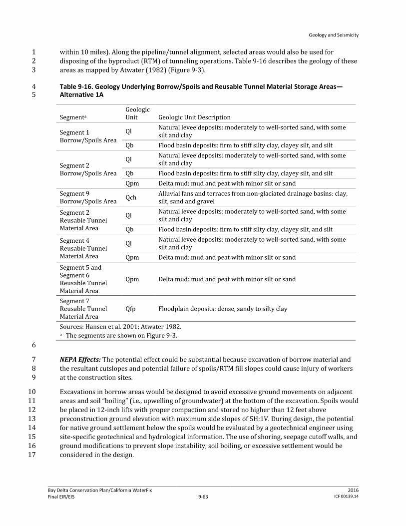
Geology and Seismicity
Bay Delta Conservation Plan/California WaterFix Final EIR/EIS
Administrative Final 9-63
2016 ICF 00139.14
within 10 miles). Along the pipeline/tunnel alignment, selected areas would also be used for 1 disposing of the byproduct (RTM) of tunneling operations. Table 9-16 describes the geology of these 2 areas as mapped by Atwater (1982) (Figure 9-3). 3
Table 9-16. Geology Underlying Borrow/Spoils and Reusable Tunnel Material Storage Areas—4 Alternative 1A 5
Segmenta Geologic Unit Geologic Unit Description
Segment 1 Borrow/Spoils Area
Ql Natural levee deposits: moderately to well-sorted sand, with some silt and clay
Qb Flood basin deposits: firm to stiff silty clay, clayey silt, and silt
Segment 2 Borrow/Spoils Area
Ql Natural levee deposits: moderately to well-sorted sand, with some silt and clay
Qb Flood basin deposits: firm to stiff silty clay, clayey silt, and silt Qpm Delta mud: mud and peat with minor silt or sand
Segment 9 Borrow/Spoils Area Qch Alluvial fans and terraces from non-glaciated drainage basins: clay,
silt, sand and gravel
Segment 2 Reusable Tunnel Material Area
Ql Natural levee deposits: moderately to well-sorted sand, with some silt and clay
Qb Flood basin deposits: firm to stiff silty clay, clayey silt, and silt
Segment 4 Reusable Tunnel Material Area
Ql Natural levee deposits: moderately to well-sorted sand, with some silt and clay
Qpm Delta mud: mud and peat with minor silt or sand Segment 5 and Segment 6 Reusable Tunnel Material Area
Qpm Delta mud: mud and peat with minor silt or sand
Segment 7 Reusable Tunnel Material Area
Qfp Floodplain deposits: dense, sandy to silty clay
Sources: Hansen et al. 2001; Atwater 1982. a The segments are shown on Figure 9-3.
6
NEPA Effects: The potential effect could be substantial because excavation of borrow material and 7 the resultant cutslopes and potential failure of spoils/RTM fill slopes could cause injury of workers 8 at the construction sites. 9
Excavations in borrow areas would be designed to avoid excessive ground movements on adjacent 10 areas and soil “boiling” (i.e., upwelling of groundwater) at the bottom of the excavation. Spoils would 11 be placed in 12-inch lifts with proper compaction and stored no higher than 12 feet above 12 preconstruction ground elevation with maximum side slopes of 5H:1V. During design, the potential 13 for native ground settlement below the spoils would be evaluated by a geotechnical engineer using 14 site-specific geotechnical and hydrological information. The use of shoring, seepage cutoff walls, and 15 ground modifications to prevent slope instability, soil boiling, or excessive settlement would be 16 considered in the design. 17
Geology and Seismicity
Bay Delta Conservation Plan/California WaterFix Final EIR/EIS
Administrative Final 9-64
2016 ICF 00139.14
In addition to the risk of slope failure at borrow sites and spoils and RTM sites, there are also 1 potential impacts on levee stability resulting from construction of Alternative 1A water conveyance 2 facilities. The intakes would be sited along the existing Sacramento River levee system, requiring 3 reconstruction of levees to provide continued flood management. At each intake pumping plant site, 4 a new setback levee (ring levee) would be constructed. The space enclosed by the setback levee 5 would be filled up to the elevation of the top of the setback levee, creating a building pad for the 6 adjacent pumping plant. 7
As discussed in Chapter 3, Description of the Alternatives, the new levees would be designed to 8 provide an adequate Sacramento River channel cross section and to provide the same level of flood 9 protection as the existing levee and would be constructed to geometries that exceed PL 84-99 10 standards. Transition levees would be constructed to connect the existing levees to the new setback 11 levees. A typical new levee would have a broad-based, generally asymmetrical triangular cross 12 section. The levee height considered wind and wave erosion. As measured from the adjacent ground 13 surface on the landside vertically up to the elevation of the levee crest, would range from 14 approximately 20 to 45 feet to provide adequate freeboard above anticipated water surface 15 elevations. The width of the levee (toe of levee to toe of levee) would range from approximately 180 16 to 360 feet. The minimum crest width of the levee would be 20 feet; however, in some places it 17 would be larger to accommodate roadways and other features. Cut-off walls would be constructed to 18 avoid seepage, and the minimum slope of levee walls would be three units horizontal to one unit 19 vertical. All levee reconstruction would conform to applicable state and federal flood management 20 engineering and permitting requirements. 21
Depending on foundation material, foundation improvements would require excavation and 22 replacement of soil below the new levee footprint and potential ground improvement. The levees 23 would be armored with riprap—small to large angular boulders—on the waterside. Intakes would 24 be constructed using a sheetpile cofferdam in the river to create a dewatered construction area that 25 would encompass the intake site. The cofferdam would lie approximately 10–35 feet from the 26 footprint of the intake and would be built from upstream to downstream, with the downstream end 27 closed last. The distance between the face of the intake and the face of the cofferdam would be 28 dependent on the foundation design and overall dimensions. The length of each temporary 29 cofferdam would vary by intake location, but would range from 740 to 2,440 feet. Cofferdams would 30 be supported by steel sheet piles and/or king piles (heavy H-section steel piles). Installation of these 31 piles may require both impact and vibratory pile drivers. Some clearing and grubbing of levees 32 would be required prior to installation of the sheet pile cofferdam, depending on site conditions. 33 Additionally, if stone bank protection, riprap, or mature vegetation is present at intake construction 34 site, it would be removed prior to sheet pile installation. 35
As described in Section 9.3.1, Methods for Analysis, the measures would conform to applicable 36 construction, design and building codes, guidelines, and standards, such as the California Building 37 Code and USACE‘s Engineering and Design—Structural Design and Evaluation of Outlet Works. DWR 38 has made the environmental commitment (see Appendix 3B, Environmental Commitments, AMMs, 39 and CMs) that the geotechnical design recommendations are included in the construction and design 40 of project facilities and construction specifications to minimize the potential effects from failure of 41 excavations and settlement. DWR also has committed to ensure that the design specifications are 42 properly executed during construction. In particular, conformance with the following codes and 43 standards would reduce the potential risk for increased likelihood of loss of property or personal 44 injury from settlement/failure of cutslopes of borrow sites and failure of soil or RTM fill slopes 45 during construction. 46
Geology and Seismicity
Bay Delta Conservation Plan/California WaterFix Final EIR/EIS
Administrative Final 9-65
2016 ICF 00139.14
DWR Division of Engineering State Water Project—Seismic Loading Criteria Report, September 1 2012. 2
DWR Division of Flood Management FloodSAFE Urban Levee Design Criteria, May 2012. 3
8 CCR Sections 1509 and 3203. 4
Generally, the applicable codes require that facilities be built to certain factors of safety in order to 5 ensure that facilities perform as designed for the life of the structure despite various soil 6 parameters. The worker safety codes and standards specify protective measures that must be taken 7 at construction sites to minimize the risk of injury or death from structural or earth failure (e.g., 8 utilizing personal protective equipment, practicing crane and scaffold safety measures). The 9 relevant codes and standards represent performance standards that must be met by contractors and 10 these measures are subject to monitoring by state and local agencies. Cal-OSHA requirements for an 11 IIPP and the terms of the IIPP to protect worker safety are the principal measures that would be 12 enforced at construction sites. 13
Conformance to these and other applicable design specifications and standards would ensure that 14 construction of Alternative 1A would not create an increased likelihood of loss of property or injury 15 of individuals from slope failure at borrow sites and spoils and RTM storage sites. The maintenance 16 and reconstruction of levees would improve levee stability over existing conditions due to improved 17 side slopes, erosion control measures (geotextile fabrics, rock revetments, or other material), 18 seepage reduction measures, and overall mass. Therefore, there would be no adverse effect. 19
CEQA Conclusion: Settlement/failure of cutslopes of borrow sites and failure of soil/RTM fill slopes 20 could result in loss of property or personal injury during construction. However, DWR would 21 conform to Cal-OSHA and other state code requirements and conform to applicable geotechnical 22 design guidelines and standards, such as USACE design measures. Conformance with these 23 requirements and the application of accepted, proven construction engineering practices would 24 reduce any potential risk such that construction of Alternative 1A would not create an increased 25 likelihood of loss of property, personal injury or death of individuals from slope failure at borrow 26 sites and spoils and RTM storage sites. The maintenance and reconstruction of levees would 27 improve levee stability over existing conditions due to improved side slopes, erosion control 28 measures, seepage reduction measures, and overall mass. The impact would be less than significant. 29 No mitigation is required. 30
Impact GEO-5: Loss of Property, Personal Injury, or Death from Structural Failure Resulting 31 from Construction-Related Ground Motions during Construction of Water Conveyance 32 Features 33
Pile driving and other heavy equipment operations would cause vibrations that could initiate 34 liquefaction and associated ground movements in places where soil and groundwater conditions are 35 present to allow liquefaction to occur. The consequences of liquefaction could be manifested in 36 terms of compaction or settlement, loss of bearing capacity, lateral spreading (horizontal soil 37 movement), increased lateral soil pressure, and buoyancy within zones of liquefaction. These 38 consequences could cause loss of property or personal injury and could damage nearby structures 39 and levees. 40
The lateral extent (or influenced distance) of damage potential caused by pile driving and heavy 41 equipment operations depends on many factors, including soil conditions, the piling hammer used, 42 frequency of piling, and the vibration tolerance of structures and levees. 43
Geology and Seismicity
Bay Delta Conservation Plan/California WaterFix Final EIR/EIS
Administrative Final 9-66
2016 ICF 00139.14
Pile driving would be conducted at the intakes, where, based on boring logs, soil materials subject to 1 liquefaction (e.g., saturated, poorly graded sand) are present. In addition to pile driving activities, 2 construction of the water conveyance facilities would require an increased volume of truck and 3 heavy equipment traffic that may occur at some of these locations. Although the trucks and heavy 4 equipment could generate vibrations in the levees, the severity of the vibrations is not expected to 5 be capable of initiating liquefaction. Construction related to conveyance facilities would also require 6 regular access to construction sites, extending the length of the project. Some of the existing public 7 roads would be used as haul routes for the construction of conveyance facilities. Use of the state 8 highway system as haul routes will be maximized where feasible because these roadways are rated 9 for truck traffic and would generally provide the most direct and easily maneuverable routes for 10 large loads. As part of future engineering phases, haul routes needed for the construction of the 11 approved project would be refined. Construction traffic may need to access levee roads at various 12 points along SR 160 and other state routes as shown in Figure 9-7, as well as at locations shown 13 along the Pipeline/Tunnel Alignment in Figure 9-8a. Because of the volume of truck traffic that may 14 occur at some of these locations, there is the potential for some effect on levee integrity at various 15 locations depending on the site specific levee conditions along access routes. 16
During project design, site-specific geotechnical and groundwater investigations would be 17 conducted to build upon existing data (e.g., California Department of Water Resources 2010a, 18 2010b, 2011) to identify and characterize the vertical (depth) and horizontal (spatial) variability in 19 soil bearing capacity and extent of liquefiable soil. Engineering soil parameters that could be used to 20 assess the liquefaction potential, such as (SPT) blow counts, (CPT) penetration tip 21 pressure/resistance, and gradation of soil, would also be obtained. SPT blow counts and CPT tip 22 pressure are used to estimate soil resistance to cyclic loadings by using empirical relationships that 23 were developed based on occurrences of liquefaction (or lack of them) during past earthquakes. 24 The resistance then can be compared to cyclic shear stress induced by the design earthquake (i.e., 25 the earthquake that is expected to produce the strongest level of ground shaking at a site to which it 26 is appropriate to design a structure to withstand). If soil resistance is less than induced stress, the 27 potential of having liquefaction during the design earthquakes is high. It is also known that soil with 28 high “fines” (i.e., silt- and clay-sized particles) content are less susceptible to liquefaction. 29
NEPA Effects: The potential effect could be substantial because construction-related ground motions 30 could initiate liquefaction, which could cause failure of structures during construction. Some of the 31 potential levee effects that could occur during the construction in the absence of corrective 32 measures may include rutting, settlement, and slope movement. 33
During design, the facility-specific potential for liquefaction would be investigated by a geotechnical 34 engineer. The potential effects of construction vibrations on nearby structures, levees, and utilities 35 would be evaluated using specific piling information (such as pile type, length, spacing, and pile-36 driving hammer to be used). In areas determined to have a potential for liquefaction, the California-37 registered civil engineer or California-certified engineering geologist would develop design 38 strategies and construction methods to ensure that pile driving and heavy equipment operations do 39 not damage facilities under construction and surrounding structures, and do not threaten the safety 40 of workers at the site (e.g., compaction grouting, which consists of pumping a thick grout mixture 41 into the soil under high pressure forming a grout bulb which compacts the surrounding soil by 42 displacement; removal and replacement of liquefaction susceptible soil; etc.). As shown in Figure 9-43 6, much of the pipeline/tunnel alignment beginning with the Pierson District and extending south to 44 Clifton Court Forebay is in the “high” seismic vulnerability group. Two fuel stations, a concrete batch 45 plant, as well as a barge unloading facility are located in this medium to medium-high potential for 46
Geology and Seismicity
Bay Delta Conservation Plan/California WaterFix Final EIR/EIS
Administrative Final 9-67
2016 ICF 00139.14
levee liquefaction damage area. Design strategies may include predrilling or jetting, using 1 open-ended pipe piles to reduce the energy needed for pile penetration, using 2 cast-in-place-drill-hole (CIDH) piles/piers that do not require driving, using pile jacking to press 3 piles into the ground by means of a hydraulic system, or driving piles during the drier summer 4 months. Field data collected during design also would be evaluated to determine the need for and 5 extent of strengthening levees, embankments, and structures to reduce the effect of vibrations. 6 These construction methods would conform to current seismic design codes and requirements, as 7 described in Appendix 3B, Environmental Commitments, AMMs, and CMs. Such design standards 8 include USACE‘s Engineering and Design—Stability Analysis of Concrete Structures and Soil 9 Liquefaction during Earthquakes, by the Earthquake Engineering Research Institute. 10
As with the effects related to design of conveyance facilities, potential construction traffic effects on 11 levees would be assessed prior to project construction to determine specific geotechnical issues 12 related to construction traffic loading. Based on the initial assessment from field reconnaissance, 13 geotechnical exploration and analyses would be performed for levee sections that need further 14 evaluations. Should the geotechnical evaluations indicate that certain segments of existing levee 15 roads need improvements to carry the expected construction truck traffic loads, DWR is committed 16 to carry out the necessary improvements to the affected levee sections or to find an alternative route 17 that would avoid the potential deficient levee sections (Mitigation Measures TRANS-2a through 2c). 18 As discussed in Chapter 19, Transportation, Mitigation Measure TRANS-2c, all affected roadways 19 would be returned to preconstruction condition or better following construction. Implementation of 20 this measure would ensure that construction activities would not worsen pavement and levee 21 conditions, relative to existing conditions. Prior to construction, DWR would make a good faith effort 22 to enter into mitigation agreements with or to obtain encroachment permits from affected agencies 23 to verify what the location, extent, timing, and fair share cost to be paid by the DWR for any 24 necessary pre- and post-construction physical improvements. Levee roads that are identified as 25 potential haul routes and expected to carry significant construction truck traffic would be monitored 26 to ensure that truck traffic is not adversely affecting the levee and to identify the need for corrective 27 action. 28
DWR has made the environmental commitment (see Appendix 3B, Environmental Commitments, 29 AMMs, and CMs) that the construction methods recommended by the geotechnical engineer are 30 included in the design of project facilities and construction specifications to minimize the potential 31 for construction-induced liquefaction. DWR also has committed to ensure that these methods are 32 followed during construction. 33
In particular, conformance with the following codes and standards would reduce the potential risk 34 for increased likelihood of loss of property or personal injury from structural failure resulting from 35 construction-related ground motions. 36
USACE Engineering and Design—Design of Pile Foundations, EM 1110-2-2906, 1991. 37
USACE Engineering and Design—Earthquake Design and Evaluation for Civil Works Projects, 38 ER 1110-2-1806, 1995. 39
8 CCR Sections 1509 and 3203. 40
Generally, the applicable codes require that facilities be built so that if soil in the foundation or 41 surrounding area are subject to liquefaction, the removal or densifaction of the liquefiable material 42 should be considered, along with alternative foundation designs. Additionally, any modification to a 43 federal levee system would require USACE approval under 33 USC 408 (a 408 Permit). 44
Geology and Seismicity
Bay Delta Conservation Plan/California WaterFix Final EIR/EIS
Administrative Final 9-68
2016 ICF 00139.14
The worker safety codes and standards specify protective measures that must be taken at 1 construction sites to minimize the risk of injury or death from structural or earth failure (e.g., 2 utilizing personal protective equipment, practicing crane and scaffold safety measures). The 3 relevant codes and standards represent performance standards that must be met by contractors and 4 these measures are subject to monitoring by state and local agencies. Cal-OSHA requirements for an 5 IIPP and the terms of the IIPP to protect worker safety are the principal measures that would be 6 enforced at construction sites. 7
Conformance to construction method recommendations and other applicable specifications, as well 8 as implementation of Mitigation Measures TRANS-2a through 2c, would ensure that construction of 9 Alternative 1A would not create an increased likelihood of loss of property, personal injury or death 10 of individuals due to construction- and traffic-related ground motions and resulting potential 11 liquefaction in the work area. Therefore, there would be no adverse effect. 12
CEQA Conclusion: Construction-related ground motions and traffic effects could initiate 13 liquefaction, which could cause failure of structures during construction and result in injury of 14 workers at the construction sites. The impact could be significant. However, DWR would conform to 15 Cal-OSHA and other state code requirements and conform to applicable design guidelines and 16 standards, such as USACE design measures. Conformance with these requirements and the 17 application of accepted, proven construction engineering practices, in addition to implementation of 18 Mitigation Measures TRANS-2a and TRANS-2b, as well as the maintenance and reconstruction of 19 levees through Mitigation Measure TRANS-2c, would reduce any potential risk such that 20 construction of Alternative 1A would not create an increased likelihood of loss of property, personal 21 injury or death of individuals from construction-related ground motion and resulting potential 22 liquefaction in the work area and the hazard would be controlled to a level that would protect 23 worker safety (see Appendix 3B, Environmental Commitments, AMMs, and CMs). The impact would 24 be less than significant. 25
Mitigation Measure TRANS-2a: Prohibit Construction Activity on Physically Deficient 26 Roadway Segments 27
Please refer to Mitigation Measure TRANS-2a in Alternative 1A, Impact TRANS-2, in Chapter 19, 28 Transportation. 29
Mitigation Measure TRANS-2b: Limit Construction Activity on Physically Deficient 30 Roadway Segments 31
Please refer to Mitigation Measure TRANS-2b in Alternative 1A, Impact TRANS-2, in Chapter 19, 32 Transportation. 33
Mitigation Measure TRANS-2c: Improve Physical Condition of Affected Roadway Segments 34 as Stipulated in Mitigation Agreements or Encroachment Permits 35
Please refer to Mitigation Measure TRANS-2c in Alternative 1A, Impact TRANS-2, in Chapter 19, 36 Transportation. 37

Geology and Seismicity
Bay Delta Conservation Plan/California WaterFix Final EIR/EIS
Administrative Final 9-69
2016 ICF 00139.14
Impact GEO-6: Loss of Property, Personal Injury, or Death from Structural Failure Resulting 1 from Rupture of a Known Earthquake Fault during Operation of Water Conveyance Features 2
According to the available AP Fault Zone Maps, none of the Alternative 1A facilities would cross or 3 be within any known active fault zones. However, numerous AP fault zones have been mapped west 4 of the conveyance alignment (Figure 9-5). The closest AP fault zone would be the Greenville fault, 5 located approximately 7.6 miles west of the conveyance facilities. Because none of the Alternative 6 1A constructed facilities would be within any of the fault zones (which include the area 7 approximately 200 to 500 feet on each side of the mapped surface trace to account for potential 8 branches of active faults), the potential that the facilities would be directly subject to fault offsets is 9 negligible. 10
In the Delta, active or potentially active blind thrust faults were identified in the seismic study. 11 Segments 3, 4, and 5 of the Alternative 1A conveyance alignment (Figure 9-5) would cross the 12 Thornton Arch fault zone. The western part of the proposed Byron Tract Forebay adjacent to the 13 Clifton Court Forebay is underlain by the West Tracy fault. Although these blind thrusts are not 14 expected to rupture to the ground surface under the forebays during earthquake events, they may 15 produce ground or near-ground shear zones, bulging, or both (California Department of Water 16 Resources 2007a). If the West Tracy fault is potentially active, it could cause surface deformation in 17 the western part of the Clifton Court Forebay. Because the western part of the Byron Tract Forebay 18 is also underlain by the hanging wall of the fault, this part of the forebay may also experience uplift 19 and resultant surface deformation (Fugro Consultants 2011). In the seismic study (California 20 Department of Water Resources 2007a), the Thornton Arch and West Tracy blind thrusts have been 21 assigned 20% and 90% probabilities of being active, respectively. The depth to the Thornton Arch 22 blind thrust is unknown. The seismic study indicates that the West Tracy fault dies out as a 23 discernible feature within approximately 3,000 to 6,000 feet below ground surface (bgs) [in the 24 upper 1- to 2-second depth two-way time, estimated to be approximately 3,000 to 6,000 feet using 25 the general velocity function as published in the Association of Petroleum Geologists Pacific Section 26 newsletter (Tolmachoff 1993)]. 27
It appears that the potential of having any shear zones, bulging, or both at the depths of the 28 pipeline/tunnel is low because the depth to the blind thrust faults is generally deep and there is no 29 credible evidence to indicate that the faults could experience displacement within the depth of the 30 pipeline/tunnel. 31
NEPA Effects: The effect would not be adverse because no active faults extend into the Alternative 32 1A alignment. Additionally, although the Thornton Arch and West Tracy blind thrusts occur beneath 33 the Alternative 1A alignment, they do not present a hazard of surface rupture based on available 34 information, including the AP Earthquake Fault Zone Map showing faults capable of surface rupture 35 (Figure 9-5). 36
However, because there is limited information regarding the depths of the Thornton Arch and West 37 Tracy blind thrusts, seismic surveys would be performed on the blind thrust during the design phase 38 to determine the depths to the top of the faults. More broadly, design-level geotechnical studies 39 would be prepared by a geotechnical engineer licensed in the state of California during project 40 design. The studies would further assess site-specific conditions at and near all the project facility 41 locations, including seismic activity, soil liquefaction, and other potential geologic and soil-related 42 hazards. This information would be used to verify assumptions and conclusions included in the 43 EIR/EIS. The geotechnical engineer’s recommended measures to address adverse conditions would 44

Geology and Seismicity
Bay Delta Conservation Plan/California WaterFix Final EIR/EIS
Administrative Final 9-70
2016 ICF 00139.14
conform to applicable design codes, guidelines, and standards. Potential design strategies or 1 conditions could include avoidance (deliberately positioning structures and lifelines to avoid 2 crossing identified shear rupture zones), geotechnical engineering (using the inherent capability of 3 unconsolidated geomaterials to “locally absorb” and distribute distinct bedrock fault movements) 4 and structural engineering (engineering the facility to undergo some limited amount of ground 5 deformation without collapse or significant damage). 6
As described in Section 9.3.1, Methods for Analysis, such design codes, guidelines, and standards are 7 environmental commitments by DWR (see also Appendix 3B, Environmental Commitments, AMMs, 8 and CMs). For construction of the water conveyance facilities, the codes and standards would 9 include the California Building Code and resource agency and professional engineering 10 specifications, such as the Division of Safety of Dams Guidelines for Use of the Consequence-Hazard 11 Matrix and Selection of Ground Motion Parameters, DWR’s Division of Flood Management FloodSAFE 12 Urban Levee Design Criteria, and USACE‘s Engineering and Design—Earthquake Design and 13 Evaluation for Civil Works Projects. These codes and standards include minimum performance 14 standards for structural design, given site-specific subsurface conditions. 15
DWR would ensure that the geotechnical design recommendations are included in the design of 16 project facilities and construction specifications to minimize the potential effects from seismic 17 events and the presence of adverse soil conditions. DWR would also ensure that the design 18 specifications are properly executed during construction. 19
In particular, conformance with the following codes and standards would reduce the potential risk 20 for increased likelihood of loss of property or personal injury from structural failure resulting from 21 surface rupture resulting from a seismic event during operation. 22
DWR Division of Engineering State Water Project—Seismic Loading Criteria Report, September 23 2012. 24
USACE Engineering and Design—Time-History Dynamic Analysis of Concrete Hydraulic Structures, 25 EM 1110-2-6051, 2003. 26
USACE Engineering and Design—Response Spectra and Seismic Analysis for Concrete Hydraulic 27 Structures, EM 1110-2-6050, 1999. 28
American Society of Civil Engineers Minimum Design Loads for Buildings and Other Structures, 29 ASCE/SEI 7-10, 2010. 30
California Code of Regulations, Title 8, Section 3203. 31
Generally, the applicable codes require that facilities be built so that they incur minimal damage in 32 the event of a foreseeable seismic event and that they remain functional following such an event and 33 that the facility is able to perform without catastrophic failure in the event of a maximum design 34 earthquake (the greatest earthquake reasonably expected to be generated by a specific source on 35 the basis of seismological and geological evidence). 36
The worker safety codes and standards specify protective measures that must be taken at 37 workplaces to minimize the risk of injury or death from structural or earth failure (e.g., utilizing 38 personal protective equipment). The relevant codes and standards represent performance 39 standards that must be met by employers and these measures are subject to monitoring by state and 40 local agencies. Cal-OSHA requirements for an IIPP and the terms of the IIPP to protect worker safety 41 are the principal measures that would be enforced at workplaces. 42
Geology and Seismicity
Bay Delta Conservation Plan/California WaterFix Final EIR/EIS
Administrative Final 9-71
2016 ICF 00139.14
Conformance to these and other applicable design specifications and standards would ensure that 1 operation of Alternative 1A would not create an increased likelihood of loss of property or injury in 2 the event of ground movement in the vicinity of the Thornton Arch fault zone and West Tracy blind 3 thrust and would not jeopardize the integrity of the surface and subsurface facilities along the 4 Alternative 1A conveyance alignment or the proposed forebay and associated facilities adjacent to 5 the Clifton Court Forebay. Therefore, there would be no adverse effect. 6
CEQA Conclusion: There are no active faults capable of surface rupture that extend into the 7 pipeline/tunnel alignment. Although the Thornton Arch and West Tracy blind thrusts occur beneath 8 the pipeline/tunnel alignment, they do not present a hazard of surface rupture based on available 9 information. Conformance to applicable design specifications and standards would ensure that 10 operation of Alternative 1A would not create an increased likelihood of loss of property or injury of 11 individuals in the event of ground movement in the vicinity of the Thornton Arch fault zone and 12 West Tracy blind thrusts. Therefore, such ground movements would not jeopardize the integrity of 13 the surface and subsurface facilities along the Alternative 1A conveyance alignment or the proposed 14 forebay and associated facilities adjacent to the Clifton Court Forebay. There would be no impact. No 15 mitigation is required. 16
Impact GEO-7: Loss of Property, Personal Injury, or Death from Structural Failure Resulting 17 from Strong Seismic Shaking during Operation of Water Conveyance Features 18
Earthquake events may occur on the local and regional seismic sources during operation of the 19 Alternative 1A water conveyance facilities. The ground shaking could damage pipelines, tunnels, 20 intakes, pumping plants, and other facilities, disrupting the water supply through the conveyance 21 system. Table 9-17 shows that the proposed facilities would be subject to moderate-to-high 22 earthquake ground shaking through 2025. All facilities would be designed and constructed in 23 accordance with the requirements of the design guidelines and building codes described in 24 Appendix 3B, Environmental Commitments, AMMs, and CMs. Site-specific geotechnical information 25 would be used to further assess the effects of local soil on the OBE and MDE ground shaking and to 26 develop design criteria that minimize damage potential facilities, pumping plants, and other 27 facilities disrupting the water supply through the conveyance system. In an extreme event of strong 28 seismic shaking, uncontrolled release of water from damaged pipelines, tunnels, intake facilities, 29 pumping plants, and other facilities could cause flooding, disruption of water supplies to the south, 30 inundation of structures, property loss, and injury. These effects are discussed more fully in 31 Appendix 3E, Potential Seismicity and Climate Change Risks to SWP/CVP Water Supplies. 32
Table 9-17 lists the expected PGA and 1.0-Sa values in 2025 at selected facility locations. For early 33 long-term, earthquake ground motions with return periods of 144 years and 975 years were 34 estimated from the results presented in the seismic study (California Department of Water 35 Resources 2007a). The 144-year and 975-year ground motions correspond to the OBE (i.e., an 36 earthquake that has a 50% probability of exceedance in a 100-year period (which is equivalent to a 37 144-year return period event) and the MDE (i.e., an earthquake that causes ground motions that 38 have a 10% chance of being exceeded in 100 years) design ground motions, respectively. Values 39 were estimated for a stiff soil site (as predicted in the seismic study), and for the anticipated soil 40 conditions at the facility locations. No seismic study results exist for 2025, so the ground shaking 41 estimated for the 2050 were used for Early Long-term (2025). 42
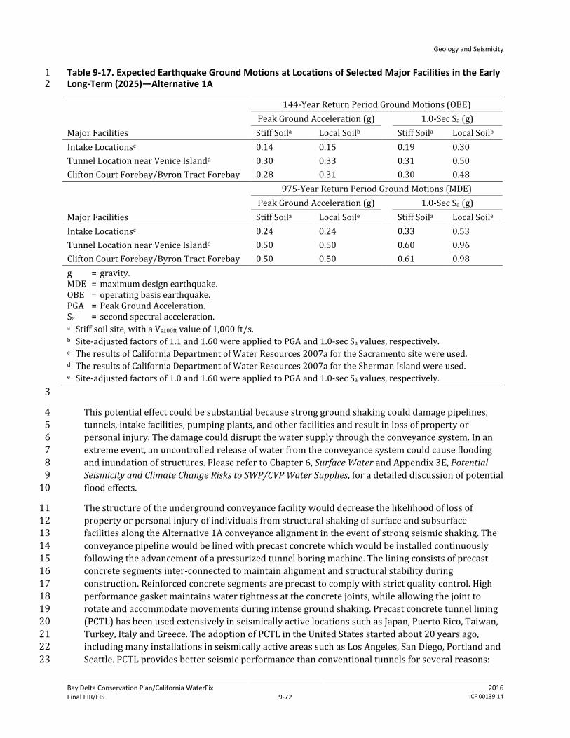
Geology and Seismicity
Bay Delta Conservation Plan/California WaterFix Final EIR/EIS
Administrative Final 9-72
2016 ICF 00139.14
Table 9-17. Expected Earthquake Ground Motions at Locations of Selected Major Facilities in the Early 1 Long-Term (2025)—Alternative 1A 2
Major Facilities
144-Year Return Period Ground Motions (OBE) Peak Ground Acceleration (g)
1.0-Sec Sa (g)
Stiff Soila Local Soilb Stiff Soila Local Soilb Intake Locationsc 0.14 0.15 0.19 0.30 Tunnel Location near Venice Islandd 0.30 0.33 0.31 0.50 Clifton Court Forebay/Byron Tract Forebay 0.28 0.31 0.30 0.48
Major Facilities
975-Year Return Period Ground Motions (MDE) Peak Ground Acceleration (g)
1.0-Sec Sa (g)
Stiff Soila Local Soile Stiff Soila Local Soile Intake Locationsc 0.24 0.24 0.33 0.53 Tunnel Location near Venice Islandd 0.50 0.50 0.60 0.96 Clifton Court Forebay/Byron Tract Forebay 0.50 0.50 0.61 0.98 g = gravity. MDE = maximum design earthquake. OBE = operating basis earthquake. PGA = Peak Ground Acceleration. Sa = second spectral acceleration. a Stiff soil site, with a Vs100ft value of 1,000 ft/s. b Site-adjusted factors of 1.1 and 1.60 were applied to PGA and 1.0-sec Sa values, respectively. c The results of California Department of Water Resources 2007a for the Sacramento site were used. d The results of California Department of Water Resources 2007a for the Sherman Island were used. e Site-adjusted factors of 1.0 and 1.60 were applied to PGA and 1.0-sec Sa values, respectively. 3
This potential effect could be substantial because strong ground shaking could damage pipelines, 4 tunnels, intake facilities, pumping plants, and other facilities and result in loss of property or 5 personal injury. The damage could disrupt the water supply through the conveyance system. In an 6 extreme event, an uncontrolled release of water from the conveyance system could cause flooding 7 and inundation of structures. Please refer to Chapter 6, Surface Water and Appendix 3E, Potential 8 Seismicity and Climate Change Risks to SWP/CVP Water Supplies, for a detailed discussion of potential 9 flood effects. 10
The structure of the underground conveyance facility would decrease the likelihood of loss of 11 property or personal injury of individuals from structural shaking of surface and subsurface 12 facilities along the Alternative 1A conveyance alignment in the event of strong seismic shaking. The 13 conveyance pipeline would be lined with precast concrete which would be installed continuously 14 following the advancement of a pressurized tunnel boring machine. The lining consists of precast 15 concrete segments inter-connected to maintain alignment and structural stability during 16 construction. Reinforced concrete segments are precast to comply with strict quality control. High 17 performance gasket maintains water tightness at the concrete joints, while allowing the joint to 18 rotate and accommodate movements during intense ground shaking. Precast concrete tunnel lining 19 (PCTL) has been used extensively in seismically active locations such as Japan, Puerto Rico, Taiwan, 20 Turkey, Italy and Greece. The adoption of PCTL in the United States started about 20 years ago, 21 including many installations in seismically active areas such as Los Angeles, San Diego, Portland and 22 Seattle. PCTL provides better seismic performance than conventional tunnels for several reasons: 23

Geology and Seismicity
Bay Delta Conservation Plan/California WaterFix Final EIR/EIS
Administrative Final 9-73
2016 ICF 00139.14
higher quality control using precast concrete 1
better ring-build precision with alignment connectors 2
backfill grouting for continuous ground to tunnel support 3
segment joints provide flexibility and accommodate deformation during earthquakes 4
high performance gasket to maintain water tightness during and after seismic movement 5
Reviewing the last 20 years of PCTL seismic performance histories, it can be concluded that little or 6 no damage to PCTL was observed for major earthquakes around the world. Case studies of the 7 response of PCTL to large seismic events have shown that PCTL should not experience significant 8 damage for ground acceleration less than 0.5g (Dean et al. 2006). The design PGA for a 975-year 9 return period is 0.49g (California Department of Water Resources 2010i: Table 4-4). Based on this 10 preliminary data, the Delta tunnels can be designed to withstand the anticipated seismic loads. 11
Design-level geotechnical studies would be conducted by a licensed civil engineer who practices in 12 geotechnical engineering. The studies would assess site-specific conditions at and near all the 13 project facility locations and provide the basis for designing the conveyance features to withstand 14 the peak ground acceleration caused by fault movement in the region. The geotechnical report will 15 contain site-specific evaluations of the seismic hazard affecting the project, and will identify portions 16 of the project site containing seismic hazards. The report will also identify any known off-site 17 seismic hazards that could adversely affect the site in the event of an earthquake and make 18 recommendations for appropriate mitigation as required by 14 CCR 3724(a). The California-19 registered civil engineer or California-certified engineering geologist’s recommended measures to 20 address this hazard would conform to applicable design codes, guidelines, and standards. Design 21 strategies could include measures such as slope stabilization and removing or replacing 22 liquefaction-prone soil during grading, site strengthening through dynamic compaction methods, 23 deep densification of the soil through blasting, or other site improvement methods. 24
As described in Section 9.3.1, Methods for Analysis, and in Appendix 3B, Environmental Commitments, 25 AMMs, and CMs, such design codes, guidelines, and standards include the California Building Code 26 and resource agency and professional engineering specifications, such as the Division of Safety of 27 Dams Guidelines for Use of the Consequence-Hazard Matrix and Selection of Ground Motion 28 Parameters, DWR‘s Division of Flood Management FloodSAFE Urban Levee Design Criteria, and 29 USACE‘s Engineering and Design—Earthquake Design and Evaluation for Civil Works Projects. 30 Conformance with these codes and standards are an environmental commitment by DWR to ensure 31 that ground shaking risks are minimized as the water conveyance features are operated. 32
DWR would ensure that the geotechnical design recommendations are included in the design of 33 project facilities and construction specifications to minimize the potential effects from seismic 34 events and the presence of adverse soil conditions. DWR would also ensure that the design 35 specifications are properly executed during construction. See Appendix 3B, Environmental 36 Commitments, AMMs, and CMs. 37
In particular, conformance with the following codes and standards would reduce the potential risk 38 for increased likelihood of loss of property or personal injury from structural failure resulting from 39 strong seismic shaking of water conveyance features during operations. 40
DWR Division of Engineering State Water Project—Seismic Loading Criteria Report, September 41 2012. 42
Geology and Seismicity
Bay Delta Conservation Plan/California WaterFix Final EIR/EIS
Administrative Final 9-74
2016 ICF 00139.14
USACE Engineering and Design—Time-History Dynamic Analysis of Concrete Hydraulic Structures, 1 EM 1110-2-6051, 2003. 2
USACE Engineering and Design—Response Spectra and Seismic Analysis for Concrete Hydraulic 3 Structures, EM 1110-2-6050, 1999. 4
American Society of Civil Engineers Minimum Design Loads for Buildings and Other Structures, 5 ASCE/SEI 7-10, 2010. 6
8 CCR 3203. 7
Generally, the applicable codes require that facilities be built so that they incur minimal damage in 8 the event of a foreseeable seismic event and that they remain functional following such an event and 9 that the facility is able to perform without catastrophic failure in the event of a maximum design 10 earthquake (the greatest earthquake reasonably expected to be generated by a specific source on 11 the basis of seismological and geological evidence). 12
NEPA Effects: Conformance with the aforementioned standards and codes are an environmental 13 commitment of the project (see Appendix 3B, Environmental Commitments, AMMs, and CMs). The 14 worker safety codes and standards specify protective measures that must be taken at workplaces to 15 minimize the risk of injury or death from structural or earth failure (e.g., utilizing personal 16 protective equipment). The relevant codes and standards represent performance standards that 17 must be met by employers and these measures are subject to monitoring by state and local agencies. 18 Cal-OSHA requirements for an IIPP and the terms of the IIPP to protect worker safety are the 19 principal measures that would be enforced at workplaces during operations. 20
Conformance to these and other applicable design specifications and standards would ensure that 21 operation of Alternative 1A would not create an increased likelihood of loss of property, personal 22 injury or death of individuals from structural shaking of surface and subsurface facilities along the 23 Alternative 1A conveyance alignment in the event of strong seismic shaking. Therefore, there would 24 be no adverse effect. 25
CEQA Conclusion: Seismically induced strong ground shaking could damage pipelines, tunnels, 26 intake facilities, pumping plants, and other facilities and result in loss of property or personal injury. 27 The damage could disrupt the water supply through the conveyance system. In an extreme event, an 28 uncontrolled release of water from the damaged conveyance system could cause flooding and 29 inundation of structures. However, through the final design process, measures to address this 30 hazard would be required to conform to applicable design codes, guidelines, and standards. As 31 described in Section 9.3.1, Methods for Analysis, and in Appendix 3B, Environmental Commitments, 32 AMMs, and CMs, such design codes, guidelines, and standards include the California Building Code 33 and resource agency and professional engineering specifications, such as the Division of Safety of 34 Dams Guidelines for Use of the Consequence-Hazard Matrix and Selection of Ground Motion 35 Parameters, DWR‘s Division of Flood Management FloodSAFE Urban Levee Design Criteria, and 36 USACE‘s Engineering and Design—Earthquake Design and Evaluation for Civil Works Projects. 37 Conformance with these codes and standards is an environmental commitment by DWR to ensure 38 that ground shaking risks are minimized as the Alternative 1A water conveyance features are 39 operated and there would be no increased likelihood of loss of property, personal injury or death of 40 individuals. The hazard would be controlled to a safe level. The impact would be less than 41 significant. No mitigation is required. 42

Geology and Seismicity
Bay Delta Conservation Plan/California WaterFix Final EIR/EIS
Administrative Final 9-75
2016 ICF 00139.14
Impact GEO-8: Loss of Property, Personal Injury, or Death from Structural Failure Resulting 1 from Seismic-Related Ground Failure (Including Liquefaction) during Operation of Water 2 Conveyance Features 3
Earthquake-induced ground shaking could cause liquefaction, resulting in soil slumping or lateral 4 spreading and subsequent damage to or breaching of water conveyance structures and facilities. The 5 consequences of liquefaction are manifested in terms of compaction or settlement, loss of bearing 6 capacity, lateral spreading (soil movement), increased lateral soil pressure, and buoyancy within 7 zones of liquefaction. Failure of tunnels, pipelines, levees, bridges, and other structures and facilities 8 could result in loss of property or personal injury, and disrupt SWP and CVP water supply deliveries. 9 The potential for adverse impacts from flooding as a result of levee or dam failure is also discussed 10 in Chapter 6, Surface Water. 11
The native soil underlying Alternative 1A facilities consist of various channel deposits and recent 12 silty and sandy alluvium at shallow depths. The available data along the southern portion of the 13 conveyance (from approximately Potato Slough to Clifton Court Forebay) show that the recent 14 alluvium overlies peaty or organic soil, which in turn is underlain by layers of mostly sandy and silty 15 soil (Real and Knudsen 2009). Soil borings advanced by DWR along the northern portion of the 16 conveyance (from approximately Potato Slough to Intake 1) show the surface soil as being similar to 17 the range reported for the southern portion, but locally containing strata of clayey silt and lean clay. 18 Because the borings were made over water, peat was usually absent from the boring logs (California 19 Department of Water Resources 2011). This may be because the peat had floated from the bottom of 20 the waterways over time, or may be because the absence of peat indicates that the watercourse’s 21 present course has not deviated greatly since the late Pleistocene. 22
The silty and sandy soil deposits underlying the peaty and organic soil over parts of the Delta are 23 late-Pleistocene age dune sand, which are liquefiable during major earthquakes. The tops of these 24 materials are exposed in some areas, but generally lie beneath the peaty soil at depths of about 10–25 40 feet bgs along the pipeline/tunnel alignment (Real and Knudsen 2009). Liquefaction hazard 26 mapping by Real and Knudsen (2009), which covers only the southwestern part of the Plan Area, 27 including the part of the alignment from near Isleton to the Palm Tract, indicates that the lateral 28 ground deformation potential would range from <0.1 to 6.0 feet. Liquefaction-induced ground 29 settlement during the 1906 San Francisco earthquake was also reported near Alternative 1A 30 facilities at a bridge crossing over Middle River just north of Woodward Island (Youd and Hoose 31 1978). Local variations in thickness and lateral extent of liquefiable soil may exist, and they may 32 have important influence on liquefaction-induced ground deformations. 33
NEPA Effects: Figure 9-6 shows that the Alternative 1A alignment has no substantial levee damage 34 potential from liquefaction in its extreme northern part and low to medium-high levee damage 35 potential throughout the remainder of the Plan Area. 36
Because the tunnel invert would be at depths of 100–160 feet bgs, the potential effects on these 37 facilities due to liquefaction is judged to be low. However, the surface and near-surface facilities that 38 would be constructed at the access road, intake, pumping plant, and forebay areas would likely be 39 founded on liquefiable soil. 40
The potential effect could be substantial because seismically induced ground shaking could cause 41 liquefaction, which could result in loss of property or personal injury, and damage pipelines, tunnels, 42 intake facilities, pumping plants, and other facilities. The damage could disrupt the water supply 43

Geology and Seismicity
Bay Delta Conservation Plan/California WaterFix Final EIR/EIS
Administrative Final 9-76
2016 ICF 00139.14
through the conveyance system. In an extreme event, an uncontrolled release of water from the 1 damaged conveyance system could cause flooding and inundation of structures. 2
In the process of preparing final facility designs, site-specific geotechnical and groundwater 3 investigations would be conducted to identify and characterize the vertical (depth) and horizontal 4 (spatial) extents of liquefiable soil. Engineering soil parameters that could be used to further assess 5 the liquefaction potential, such as SPT blow counts, CPT penetration tip pressure/resistance, and 6 gradation of soil, would also be obtained. SPT blow counts and CPT tip pressure are used to estimate 7 soil resistance to cyclic loadings by using empirical relationships that were developed based on 8 occurrences of liquefaction (or lack of them) during past earthquakes. The resistance then can be 9 compared to cyclic shear stress induced by the design earthquake. If soil resistance is less than 10 induced stress, the potential of having liquefaction during the design earthquakes is high. It is also 11 known that soil with high “fines” (i.e., silt- and clay-sized particles) content are less susceptible to 12 liquefaction. 13
During final design, site-specific potential for liquefaction would be investigated by a geotechnical 14 engineer. In areas determined to have a potential for liquefaction, a California-registered civil 15 engineer or California-certified engineering geologist would develop design measures and 16 construction methods to meet design criteria established by building codes and construction 17 standards to ensure that the design earthquake does not cause damage to or failure of the facility. 18 Such measures and methods include removing and replacing potentially liquefiable soil, 19 strengthening foundations (for example, using post-tensioned slab, reinforced mats, and piles) to 20 resist excessive total and differential settlements, and using in situ ground improvement techniques 21 (such as deep dynamic compaction, vibro-compaction, vibro-replacement, compaction grouting, and 22 other similar methods). The results of the site-specific evaluation and California-registered civil 23 engineer or California-certified engineering geologist’s recommendations would be documented in a 24 detailed geotechnical report prepared in accordance with state guidelines, in particular Guidelines 25 for Evaluating and Mitigating Seismic Hazards in California (California Geological Survey 2008). As 26 described in Section 9.3.1, Methods for Analysis, and in Appendix 3B, Environmental Commitments, 27 AMMs, and CMs, such design codes, guidelines, and standards include USACE‘s Engineering and 28 Design—Stability Analysis of Concrete Structures and Soil Liquefaction during Earthquakes, by the 29 Earthquake Engineering Research Institute. Conformance with these design requirements is an 30 environmental commitment by DWR to ensure that liquefaction risks are minimized as the water 31 conveyance features are operated. 32
DWR would ensure that the geotechnical design recommendations are included in the design of 33 project facilities and construction specifications to minimize the potential effects from liquefaction 34 and associated hazards. DWR would also ensure that the design specifications are properly executed 35 during construction. 36
In particular, conformance with the following codes and standards would reduce the potential risk 37 for increased likelihood of loss of property or personal injury from structural failure resulting from 38 strong seismic shaking of water conveyance features during operations. 39
DWR Division of Engineering State Water Project—Seismic Loading Criteria Report, September 40 2012. 41
USACE Engineering and Design—Time-History Dynamic Analysis of Concrete Hydraulic Structures, 42 EM 1110-2-6051, 2003 43

Geology and Seismicity
Bay Delta Conservation Plan/California WaterFix Final EIR/EIS
Administrative Final 9-77
2016 ICF 00139.14
USACE Engineering and Design—Response Spectra and Seismic Analysis for Concrete Hydraulic 1 Structures, EM 1110-2-6050, 1999. 2
American Society of Civil Engineers Minimum Design Loads for Buildings and Other Structures, 3 ASCE/SEI 7-10, 2010. 4
USACE Engineering and Design—Design of Pile Foundations, EM 1110-2-2906, 1991 5
8 CCR 3203. 6
Generally, the applicable codes require that facilities be built so that if soil in the foundation or 7 surrounding area are subject to liquefaction, the removal or densifaction of the liquefiable material 8 should be considered, along with alternative foundation designs. Additionally, any modification to a 9 federal levee system would require USACE approval under 33 USC 408 (a 408 Permit). 10
The worker safety codes and standards specify protective measures that must be taken at 11 workplaces to minimize the risk of injury or death from structural or earth failure (e.g., utilizing 12 personal protective equipment). The relevant codes and standards represent performance 13 standards that must be met by employers and these measures are subject to monitoring by state and 14 local agencies. Cal-OSHA requirements for an IIPP and the terms of the IIPP to protect worker safety 15 are the principal measures that would be enforced at workplaces during operations. 16
Conformance to these and other applicable design specifications and standards would ensure that 17 the hazard of liquefaction and associated ground movements would not create an increased 18 likelihood of loss of property, personal injury or death of individuals from structural failure 19 resulting from seismic-related ground failure along the Alternative 1A conveyance alignment during 20 operation of the water conveyance features. Therefore, the effect would not be adverse. 21
CEQA Conclusion: Seismically induced ground shaking could cause liquefaction. Liquefaction could 22 damage pipelines, tunnels, intake facilities, pumping plants, and other facilities, and thereby disrupt 23 the water supply through the conveyance system. In an extreme event, an uncontrolled release of 24 water from the damaged conveyance system could cause flooding and inundation of structures. 25 However, through the final design process, measures to address the liquefaction hazard would be 26 required to conform to applicable design codes, guidelines, and standards. As described in Section 27 9.3.1, Methods for Analysis, and in Appendix 3B, Environmental Commitments, AMMs, and CMs, such 28 design codes, guidelines, and standards include USACE‘s Engineering and Design—Stability Analysis 29 of Concrete Structures and Soil Liquefaction during Earthquakes, by the Earthquake Engineering 30 Research Institute. Conformance with these design standards is an environmental commitment by 31 DWR to ensure that liquefaction risks are minimized as the Alternative 1A water conveyance 32 features are operated and there would be no increased likelihood of loss of property, personal injury 33 or death of individuals. The hazard would be controlled to a safe level. The impact would be less 34 than significant. No mitigation is required. 35
Impact GEO-9: Loss of Property, Personal Injury, or Death from Landslides and Other Slope 36 Instability during Operation of Water Conveyance Features 37
Alternative 1A would involve excavation that creates new cut-and-fill slopes and construction of 38 new embankments and levees. As a result of ground shaking and high soil-water content during 39 heavy rainfall, existing and new slopes that are not properly engineered and natural stream banks 40 could fail and cause damage to facilities. Levees can fail for several reasons: 1) high velocities of 41 water flow can result in high rates of erosion and erode and overtop a levee; 2) the higher velocities 42
Geology and Seismicity
Bay Delta Conservation Plan/California WaterFix Final EIR/EIS
Administrative Final 9-78
2016 ICF 00139.14
of water flow can also lead to higher rates of erosion along the inner parts of levees and lead to 1 undercutting and clumping of the levee into the river. Heavy rainfall or seepage into the levee from 2 the river can increase fluid pressure in the levee and lead to slumping on the outer parts of the levee. 3 If the slumps grow to the top of the levee, large sections of the levee may slump onto the floodplain 4 and lower the elevation of the top of the levee, leading to overtopping; 3) increasing levels of water 5 in the river will cause the water table in the levee to rise which will increase fluid pressure and may 6 result in seepage and eventually lead to internal erosion called piping. Piping will erode the material 7 under the levee, undermining it and causing its collapse and failure. 8
With the exception of levee slopes and natural stream banks, the topography along the Alternative 9 1A conveyance alignment is nearly level to very gently sloping. The areas that may be susceptible to 10 slope failure are along existing levee slopes, and at intakes, pumping plants, forebay, and certain 11 access road locations. Outside these areas, the land is nearly level and consequently has a negligible 12 potential for slope failure. Based on review of topographic maps and a landslide map of Alameda 13 County (Roberts et al. 1999), the conveyance facilities would not be constructed on, nor would it be 14 adjacent to, slopes that are subject to mudflows/debris flows from natural slopes. 15
NEPA Effects: The potential effect could be substantial because levee slopes and stream banks may 16 fail, either from high pore-water pressure caused by high rainfall and weak soil, or from seismic 17 shaking. Structures built on these slopes could be damaged or fail entirely as a result of slope 18 instability. As discussed in Impact SW-2 in Chapter 6, Surface Water, operation of the water 19 conveyance features under Alternative 1A would not result in an increase in potential risk for flood 20 management compared to existing conditions. Peak monthly flows under Alternative 1A in the 21 locations considered were similar to or less than those that would occur under existing conditions. 22 Since flows would not be substantially greater, the potential for increased rates of erosion or 23 seepage are low. For additional discussion on the possible exposure of people or structures to 24 impacts from flooding due to levee failure, please refer to Impact SW-6 in Chapter 6, Surface Water. 25
During project design, a geotechnical engineer would develop slope stability design criteria (such as 26 minimum slope safety factors and allowable slope deformation and settlement) for the various 27 anticipated loading conditions. The design criteria would be documented in a detailed geotechnical 28 report prepared in accordance with state guidelines, in particular Guidelines for Evaluating and 29 Mitigating Seismic Hazards in California (California Geological Survey 2008). As discussed in Chapter 30 3, Description of the Alternatives, the foundation soil beneath slopes, embankments, or levees could 31 be improved to increase its strength and to reduce settlement and deformation. Foundation soil 32 improvement could involve excavation and replacement with engineered fill; preloading; ground 33 modifications using jet-grouting, compaction grouting, chemical grouting, shallow soil mixing, deep 34 soil mixing, vibro-compaction, or vibro-replacement; or other methods. Engineered fill also would 35 be used to construct new slopes, embankments, and levees. Surface and internal drainage systems 36 would be installed as necessary to reduce erosion and piping (internal erosion) potential. 37
Site-specific geotechnical and hydrological information would be used, and the design would 38 conform to the current standards and construction practices, as described in Section 9.3.1, Methods 39 for Analysis, such as USACE‘s Design and Construction of Levees and USACE’s EM 1110-2-1902, Slope 40 Stability. The design requirements would be presented in a detailed geotechnical report. 41 Conformance with these design requirements is an environmental commitment by DWR to ensure 42 that slope stability hazards would be avoided as the water conveyance features are operated. DWR 43 would ensure that the geotechnical design recommendations are included in the design of cut and 44
Geology and Seismicity
Bay Delta Conservation Plan/California WaterFix Final EIR/EIS
Administrative Final 9-79
2016 ICF 00139.14
fill slopes, embankments, and levees to minimize the potential effects from slope failure. DWR would 1 also ensure that the design specifications are properly executed during construction. 2
In particular, conformance with the following codes and standards would reduce the potential risk 3 for increased likelihood of loss of property or personal injury from structural failure resulting from 4 seismic shaking or from high-pore water pressure. 5
DWR Division of Engineering State Water Project—Seismic Loading Criteria Report, September 6 2012. 7
DWR Division of Flood Management FloodSAFE Urban Levee Design Criteria, May 2012. 8
USACE Slope Stability, EM 1110-2-1902, 2003. 9
8 CCR 3203. 10
Generally, the applicable codes require that facilities be built to certain factors of safety in order to 11 ensure that facilities perform as designed for the life of the structure despite various soil 12 parameters. 13
The worker safety codes and standards specify protective measures that must be taken at 14 workplaces to minimize the risk of injury or death from structural or earth failure (e.g., utilizing 15 personal protective equipment). The relevant codes and standards represent performance 16 standards that must be met by employers and these measures are subject to monitoring by state and 17 local agencies. Cal-OSHA requirements for an IIPP and the terms of the IIPP to protect worker safety 18 are the principal measures that would be enforced at workplaces during operations. 19
Conformance to the above and other applicable design specifications and standards would ensure 20 that the hazard of slope instability would not create an increased likelihood of loss of property, 21 personal injury or death of individuals along the Alternative 1A conveyance alignment during 22 operation of the water conveyance features. Therefore, the effect would not be adverse. 23
CEQA Conclusion: Unstable levee slopes and natural stream banks may fail, either from high pore-24 water pressure caused by high rainfall and weak soil, or from seismic shaking. Structures built on 25 these slopes could be damaged or fail entirely as a result of slope instability. However, through the 26 final design process, measures to address this hazard would be required to conform to applicable 27 design codes, guidelines, and standards. The measures would be described in a detailed geotechnical 28 report prepared in accordance with state guidelines, in particular Guidelines for Evaluating and 29 Mitigating Seismic Hazards in California (California Geological Survey 2008). As described in Section 30 9.3.1, Methods for Analysis, and in Appendix 3B, Environmental Commitments, AMMs, and CMs, such 31 design codes, guidelines, and standards include the California Building Code and resource agency 32 and professional engineering specifications, such as USACE‘s Engineering and Design—Earthquake 33 Design and Evaluation for Civil Works Projects. Conformance with these codes and standards is an 34 environmental commitment by DWR to ensure cut and fill slopes and embankments will be stable as 35 the Alternative 1A water conveyance features are operated and there would be no increased 36 likelihood of loss of property, personal injury or death of individuals. The impact would be less than 37 significant. No mitigation is required. 38
Geology and Seismicity
Bay Delta Conservation Plan/California WaterFix Final EIR/EIS
Administrative Final 9-80
2016 ICF 00139.14
Impact GEO-10: Loss of Property, Personal Injury, or Death from Seiche or Tsunami during 1 Operation of Water Conveyance Features 2
Based on recorded tsunami wave heights at the Golden Gate (Contra Costa Transportation Agency 3 2009) and in the interior of the San Francisco Bay and on tsunami inundation maps prepared by the 4 California Department of Conservation (2009), the height of a tsunami wave reaching the Suisun 5 Marsh and the Delta would be small because of the distance from the ocean and attenuating effect of 6 the San Francisco Bay. Therefore, the potential hazard of loss of property or personal injury as a 7 result of a tsunami on the water conveyance facilities is low. 8
Similarly, with the exception of the Clifton Court Forebay and the Byron Tract Forebay, the potential 9 for a substantial seiche to take place in the Plan Area that would cause loss of property or personal 10 injury in the construction areas is considered low because seismic and water body geometry 11 conditions for a seiche to occur near conveyance facilities are not favorable. Fugro Consultants, Inc. 12 (2011) identified the potential for a seiche of an unspecified wave height to occur in the Clifton 13 Court Forebay, caused by strong ground motions along the underlying West Tracy fault, assuming 14 that this fault is potentially active. Since the fault also exists in the immediate vicinity of the Byron 15 Tract Forebay, a seiche could also occur in the Byron Tract Forebay. 16
NEPA Effects: The effect of a tsunami generated in the Pacific Ocean would not be adverse because 17 the distance from the ocean and attenuating effect of the San Francisco Bay would likely allow only a 18 low (i.e., less than 2 feet) tsunami wave height to reach the Delta (Contra Costa Transportation 19 Agency 2009). With the assumption of an 18-inch sea level rise at mid-century, the tsunami effect 20 would not be adverse since the attenuating effect of the San Francisco Bay (a 100-year return period 21 tsunami wave run-up elevation at Golden Gate Bridge of 8.2 feet NGVD) would dissipate as it moves 22 east toward the East Bay and the Delta. By the time it reaches the East Bay it would be half as high 23 (City and County of San Francisco 2011). As it moves to the Delta, the wave run-up is likely low (3.5 24 feet or less) tsunami wave height. 25
Because the majority of the region’s faults are strike-slip faults, a tsunami is not expected to be a 26 major threat as a result of a regional earthquake. The primary tsunami threat along the central 27 California coast is from distant earthquakes along subduction zones elsewhere in the Pacific basin, 28 including Alaska. Since 1877, Alaska earthquakes have produced tsunami run-ups in the Bay Area 29 nine times or on average, every 28 years. Historically, the run-ups from these events have been less 30 than 1 foot (City and County of San Francisco 2011). 31
In most parts of the Plan Area, the effects of a seiche would not be adverse because the seismic 32 hazard and the geometry of the water bodies (i.e., wide and shallow) near conveyance facilities are 33 not favorable for a seiche to occur. However, assuming that the West Tracy fault is potentially active, 34 a potential exists for a seiche to occur in the Clifton Court Forebay and the Byron Tract Forebay. The 35 effect could be adverse because the waves generated by a seiche could overtop the Byron Tract 36 Forebay and Clifton Court Forebay embankments, causing erosion of the embankments and 37 subsequent flooding in the vicinity. 38
However, design-level geotechnical studies would be conducted by a licensed civil engineer who 39 practices in geotechnical engineering. The studies would determine the peak ground acceleration 40 caused by movement of the West Tracy fault and the maximum probable seiche wave that could be 41 generated by the ground shaking. The California-registered civil engineer or California-certified 42 engineering geologist’s recommended measures to address this hazard, as well as the hazard of a 43 seiche overtopping the Clifton Court Forebay embankment and subsequent adverse effect on the 44

Geology and Seismicity
Bay Delta Conservation Plan/California WaterFix Final EIR/EIS
Administrative Final 9-81
2016 ICF 00139.14
Byron Tract Forebay embankment, would conform to applicable design codes, guidelines, and 1 standards. As described in Section 9.3.1, Methods for Analysis, and in Appendix 3B, Environmental 2 Commitments, AMMs, and CMs, such design codes, guidelines, and standards include the Division of 3 Safety of Dams’ Guidelines for Use of the Consequence-Hazard Matrix and Selection of Ground Motion 4 Parameters, DWR‘s Division of Flood Management FloodSAFE Urban Levee Design Criteria, and 5 USACE‘s Engineering and Design—Earthquake Design and Evaluation for Civil Works Projects. 6 Conformance with these codes and standards is an environmental commitment by DWR to ensure 7 that the adverse effects of a seiche are controlled to an acceptable level while the forebay facility is 8 operated. 9
DWR would ensure that the geotechnical design recommendations are included in the design of 10 project facilities and construction specifications to minimize the potential effects from seismic 11 events and consequent seiche waves. DWR would also ensure that the design specifications are 12 properly executed during construction. 13
In particular, conformance with the following codes and standards would reduce the potential risk 14 for increased likelihood of loss of property or personal injury from tsunami or seiche. 15
U.S. Department of the Interior and USGS, Climate Change and Water Resources Management: A 16 Federal Perspective, Circular 1331. 17
State of California Sea-Level Rise Task Force of CO-CAT, Sea-Level Rise Interim Guidance 18 Document, 2010 19
8 CCR 3203. 20
Generally, the applicable codes provide guidance on estimating the effects of climate change and sea 21 level rise and associated effects when designing a project and ensuring that a project is able to 22 respond to these effects. 23
The worker safety codes and standards specify protective measures that must be taken at 24 workplaces to minimize the risk of injury or death from structural or earth failure (e.g., utilizing 25 personal protective equipment). The relevant codes and standards represent performance 26 standards that must be met by employers and these measures are subject to monitoring by state and 27 local agencies. Cal-OSHA requirements for an IIPP and the terms of the IIPP to protect worker safety 28 are the principal measures that would be enforced at workplaces during operations. 29
Conformance to these and other applicable design specifications and standards would ensure that 30 the Byron Tract Forebay embankment would be designed and constructed to contain and withstand 31 the anticipated maximum seiche wave height and would not create an increased likelihood of loss of 32 property, personal injury or death of individuals along the Alternative 1A conveyance alignment 33 during operation of the water conveyance features. Therefore, the effect would not be adverse. 34
CEQA Conclusion: Based on recorded tsunami wave heights at the Golden Gate (Contra Costa 35 Transportation Agency 2009) and in the interior of the San Francisco Bay and on tsunami 36 inundation maps prepared by the California Department of Conservation (2009), the height of a 37 tsunami wave reaching the Suisun Marsh and the Delta would be small because of the distance from 38 the ocean and attenuating effect of the San Francisco Bay. The impact would be less than significant. 39 No mitigation is required. 40
Similarly, the potential for a significant seiche to occur in most parts of the Plan Area is considered 41 low because the seismic hazard and the geometry of the water bodies (i.e., wide and shallow) near 42

Geology and Seismicity
Bay Delta Conservation Plan/California WaterFix Final EIR/EIS
Administrative Final 9-82
2016 ICF 00139.14
conveyance facilities are not favorable for a seiche to occur. However, assuming that the West Tracy 1 fault is potentially active, a potential exists for a seiche to occur in the Clifton Court Forebay and the 2 Byron Tract Forebay (Fugro Consultants 2011). The impact would not be significant because the 3 Byron Tract Forebay embankment would be designed and constructed according to applicable 4 design codes, guidelines, and standards to contain and withstand the anticipated maximum seiche 5 wave height and potential seiche wave overtopping of the Clifton Court Forebay and Byron Tract 6 Forebay embankments as the Alternative 1A water conveyance features are operated and there 7 would be no increased likelihood of loss of property, personal injury or death of individuals. The 8 impact would be less than significant. No mitigation is required. 9
Impact GEO-11: Ground Failure Caused by Increased Groundwater Surface Elevations from 10 Unlined Canal Seepage as a Result of Operating the Water Conveyance Facilities 11
NEPA Effects: Alternative 1A would not involve construction of unlined canals; therefore, there 12 would be no increase in groundwater surface elevations and consequently no effect to groundwater 13 surface elevations caused by canal seepage. Therefore, the effect would not be adverse. 14
CEQA Conclusion: Alternative 1A would not involve construction of unlined canals; therefore, there 15 would be no increase in groundwater surface elevations and consequently no impact caused by 16 canal seepage. There would be no impact. No mitigation is required. 17
Impact GEO-12: Loss of Property, Personal Injury, or Death Resulting from Structural Failure 18 Caused by Rupture of a Known Earthquake Fault at Restoration Opportunity Areas 19
According to the available AP Earthquake Fault Zone Maps, only the Suisun Marsh ROA could be 20 affected by rupture of an earthquake fault. The active Green Valley fault crosses the southwestern 21 corner of the ROA. The active Cordelia fault extends approximately 1 mile into the northwestern 22 corner of the ROA. Rupture of these faults could damage levees and berms constructed as part of the 23 restoration, which could result in failure of the levees and flooding of otherwise protected areas. 24
Within the Delta, active or potentially active blind thrust faults were identified in the seismic study 25 (California Department of Water Resources 2007a). The extreme southeastern corner of the Suisun 26 Marsh is underlain by the Montezuma blind thrust zone. Parts of the Cache Slough and Yolo Bypass 27 ROAs are underlain by part of the North Midland blind thrust zone. The Cosumnes/Mokelumne 28 River and East Delta ROAs are underlain by the Thornton Arch zone. Although these blind thrusts 29 are not expected to rupture to the ground surface during earthquake events, they may produce 30 ground or near-ground shear zones, bulging, or both. In the seismic study (California Department of 31 Water Resources 2007a), the Thornton Arch blind thrust was assigned a 20% probability of being 32 active. The depth to the Thornton Arch blind thrust is unknown. Based on limited geologic and 33 seismic survey information, it appears that the potential of having any shear zones, bulging, or both 34 at the sites of the habitat levees is low because the depth to the blind thrust faults is generally deep. 35
NEPA Effects: The effect of implementing the conservation measures in the ROAs could be 36 substantial because rupture of the Cordelia and Green Valley faults could occur at the Suisun Marsh 37 ROA and cause damage or failure of ROA facilities, including levees and berms. Damage to these 38 features could result in their failure, causing flooding of otherwise protected areas. 39
Because there is limited information regarding the depths of the blind faults mentioned above, 40 seismic surveys would be performed in the vicinity of the faults as part of final design. These surveys 41 would be used to verify fault depths where levees and other features would be constructed. 42

Geology and Seismicity
Bay Delta Conservation Plan/California WaterFix Final EIR/EIS
Administrative Final 9-83
2016 ICF 00139.14
Collection of this depth information would be part of broader, design-level geotechnical studies 1 prepared by a geotechnical engineer licensed in the state of California to support all aspects of site-2 specific project design. The studies would assess site-specific conditions at and near all the project 3 facility locations, including the nature and engineering properties of all soil horizons and underlying 4 geologic strata, and groundwater conditions. The geotechnical engineers’ information would be used 5 to develop final engineering solutions to any hazardous condition, consistent with the code and 6 standards requirements of federal, state and local oversight agencies. As described in Section 9.3.1, 7 Methods for Analysis, and in Appendix 3B, Environmental Commitments, AMMs, and CMs, such design 8 codes, guidelines, and standards include the California Building Code and resource agency and 9 professional engineering specifications, such as the Division of Safety of Dams’ Guidelines for Use of 10 the Consequence-Hazard Matrix and Selection of Ground Motion Parameters, DWR‘s Division of Flood 11 Management FloodSAFE Urban Levee Design Criteria, and USACE‘s Engineering and Design—12 Earthquake Design and Evaluation for Civil Works Projects. Conformance with these design standards 13 is an environmental commitment by the BDCP proponents to ensure that risks from a fault rupture 14 are minimized as levees for habitat restoration areas are constructed and maintained. The hazard 15 would be controlled to a safe level by following the proper design standards. 16
The BDCP proponents would ensure that the geotechnical design recommendations are included in 17 the design of project facilities and construction specifications to minimize the potential effects from 18 seismic events and the presence of adverse soil conditions. The BDCP proponents would also ensure 19 that the design specifications are properly executed during implementation. 20
In particular, conformance with the following codes and standards would reduce the potential risk 21 for increased likelihood of loss of property or personal injury from structural failure resulting from 22 surface rupture resulting from a seismic event during operation. 23
DWR Division of Engineering State Water Project—Seismic Loading Criteria Report, September 24 2012. 25
DWR DSOD Guidelines for Use of the Consequence-Hazard Matrix and Selection of Ground Motion 26 Parameters, 2002. 27
USACE Engineering and Design—Earthquake Design and Evaluation for Civil Works Projects, 28 ER 1110-2-1806, 1995. 29
USACE Design and Construction of Levees, EM 1110-2-1913, 2000. 30
USACE (CESPK-ED-G), Geotechnical Levee Practice, SOP EDG-03, 2004. 31
DWR Division of Flood Management FloodSAFE Urban Levee Design Criteria, May 2012. 32
8 CCR Sections 1509 and 3203. 33
Generally, the applicable codes require that facilities be built so that they incur minimal damage in 34 the event of a foreseeable seismic event and that they remain functional following such an event and 35 that the facility is able to perform without catastrophic failure in the event of a maximum design 36 earthquake (the greatest earthquake reasonably expected to be generated by a specific source on 37 the basis of seismological and geological evidence). 38
The worker safety codes and standards specify protective measures that must be taken at 39 workplaces to minimize the risk of injury or death from structural or earth failure (e.g., utilizing 40 personal protective equipment, practicing crane and scaffold safety measures). The relevant codes 41 and standards represent performance standards that must be met by employers and these measures 42
Geology and Seismicity
Bay Delta Conservation Plan/California WaterFix Final EIR/EIS
Administrative Final 9-84
2016 ICF 00139.14
are subject to monitoring by state and local agencies. Cal-OSHA requirements for an IIPP and the 1 terms of the IIPP to protect worker safety are the principal measures that would be enforced at 2 workplaces. 3
Conformance to these and other applicable design specifications and standards would ensure that 4 the hazard of ground movement in the vicinity of the blind thrusts underlying the ROAs would not 5 jeopardize the integrity of the levees and other features constructed in the ROAs and would not 6 create an increased likelihood of loss of property, personal injury or death of individuals in the 7 ROAs. This effect would not be adverse. 8
CEQA Conclusion: Rupture of the Cordelia and Green Valley faults could occur at the Suisun Marsh 9 ROA and damage ROA facilities, such as levees and berms. Damage to these features could result in 10 their failure, causing flooding of otherwise protected areas. However, through the final design 11 process for conservation measures in the ROAs, measures to address the fault rupture hazard would 12 be required to conform to applicable design codes, guidelines, and standards. As described in 13 Section 9.3.1, Methods for Analysis, and in Appendix 3B, Environmental Commitments, AMMs, and 14 CMs, such design codes, guidelines, and standards include the Division of Safety of Dams’ Guidelines 15 for Use of the Consequence-Hazard Matrix and Selection of Ground Motion Parameters, DWR‘s 16 Division of Flood Management FloodSAFE Urban Levee Design Criteria, and USACE‘s Engineering and 17 Design—Earthquake Design and Evaluation for Civil Works Projects. Conformance with these design 18 standards is an environmental commitment by the BDCP proponents to ensure that fault rupture 19 risks are minimized as the conservation measures are implemented. The hazard would be controlled 20 to a safe level and there would be no increased likelihood of loss of property, personal injury or 21 death of individuals in the ROAs. The impact would be less than significant. No mitigation is 22 required. 23
Impact GEO-13: Loss of Property, Personal Injury, or Death from Structural Failure Resulting 24 from Strong Seismic Shaking at Restoration Opportunity Areas 25
Earthquake events may occur on the local and regional seismic sources at or near the ROAs. Because 26 of its proximity to these faults, the Suisun Marsh ROA would be especially subject to ground shaking 27 caused by the Concord-Green Valley fault. The Cache Slough ROA would be subject to shaking from 28 the Northern Midland fault zone, which underlies the ROA. Although more distant from these 29 sources, the other ROAs would be subject to shaking from the San Andreas, Hayward–Rodgers 30 Creek, Calaveras, Concord–Green Valley, San Gregorio, Greenville, and Mt. Diablo Thrust faults and 31 the more proximate blind thrusts in the Delta. 32
Among all the ROAs, the Suisun Marsh ROA would be most subject to ground shaking because of its 33 proximity to active faults. The Suisun Marsh ROA is subject to a PGA of approximately 0.31–0.35 g 34 for 200-year return interval, while the PGA for the other ROAs ranges from approximately 0.11–0.26 35 g. The ground shaking could damage levees and other structures, and in an extreme event cause 36 levees to fail such that protected areas flood. 37
NEPA Effects: All temporary facilities would be designed and built to meet the safety and 38 collapse-prevention requirements for the above-anticipated seismic loads. Therefore, this effect is 39 considered not adverse. No additional mitigation measures are required. All facilities would be 40 designed and constructed in accordance with the requirements of the design measures described in 41 Chapter 3, Description of the Alternatives. Site-specific geotechnical information would be used to 42 further assess the effects of local soil on the OBE and MDE ground shaking and to develop design 43 criteria that minimize the potential of damage. Design-level geotechnical studies would be prepared 44
Geology and Seismicity
Bay Delta Conservation Plan/California WaterFix Final EIR/EIS
Administrative Final 9-85
2016 ICF 00139.14
by a geotechnical engineer licensed in the state of California during project design. The studies 1 would assess site-specific conditions at and near all the project facility locations and provide the 2 basis for designing the levees and other features to withstand the peak ground acceleration caused 3 by fault movement in the region. The geotechnical engineer’s recommended measures to address 4 this hazard would conform to applicable design codes, guidelines, and standards. Potential design 5 strategies or conditions could include avoidance (deliberately positioning structures and lifelines to 6 avoid crossing identified shear rupture zones), geotechnical engineering (using the inherent 7 capability of unconsolidated geomaterials to “locally absorb” and distribute distinct bedrock fault 8 movements) and structural engineering (engineering the facility to undergo some limited amount of 9 ground deformation without collapse or significant damage). 10
As described in Section 9.3.1, Methods for Analysis, and in Appendix 3B, Environmental Commitments, 11 AMMs, and CMs, such design codes, guidelines, and standards include the California Building Code 12 and resource agency and professional engineering specifications, such as the Division of Safety of 13 Dams Guidelines for Use of the Consequence-Hazard Matrix and Selection of Ground Motion 14 Parameters, DWR‘s Division of Flood Management FloodSAFE Urban Levee Design Criteria, and 15 USACE‘s Engineering and Design—Earthquake Design and Evaluation for Civil Works Projects. 16 Conformance with these design standards is an environmental commitment by the BDCP 17 proponents to ensure that strong seismic shaking risks are minimized as the conservation measures 18 are implemented. 19
The BDCP proponents would ensure that the geotechnical design recommendations are included in 20 the design of project features and construction specifications to minimize the potential effects from 21 seismic events and the presence of adverse soil conditions. The BDCP proponents would also ensure 22 that the design specifications are properly executed during implementation. 23
In particular, conformance with the following codes and standards would reduce the potential risk 24 for increased likelihood of loss of property or personal injury from structural failure resulting from 25 surface rupture resulting from a seismic event during operation. 26
DWR Division of Engineering State Water Project—Seismic Loading Criteria Report, September 27 2012. 28
DWR DSOD Guidelines for Use of the Consequence-Hazard Matrix and Selection of Ground Motion 29 Parameters, 2002. 30
USACE Engineering and Design—Earthquake Design and Evaluation for Civil Works Projects, 31 ER 1110-2-1806, 1995. 32
USACE Design and Construction of Levees, EM 1110-2-1913, 2000. 33
USACE (CESPK-ED-G), Geotechnical Levee Practice, SOP EDG-03, 2004. 34
DWR Division of Flood Management FloodSAFE Urban Levee Design Criteria, May 2012. 35
8 CCR Sections 1509 and 3203. 36
Generally, the applicable codes require that facilities be built so that they incur minimal damage in 37 the event of a foreseeable seismic event and that they remain functional following such an event and 38 that the facility is able to perform without catastrophic failure in the event of a maximum design 39 earthquake (the greatest earthquake reasonably expected to be generated by a specific source on 40 the basis of seismological and geological evidence). 41

Geology and Seismicity
Bay Delta Conservation Plan/California WaterFix Final EIR/EIS
Administrative Final 9-86
2016 ICF 00139.14
The worker safety codes and standards specify protective measures that must be taken at 1 workpkaces to minimize the risk of injury or death from structural or earth failure (e.g., utilizing 2 personal protective equipment, practicing crane and scaffold safety measures). The relevant codes 3 and standards represent performance standards that must be met by employers and these measures 4 are subject to monitoring by state and local agencies. Cal-OSHA requirements for an IIPP and the 5 terms of the IIPP to protect worker safety are the principal measures that would be enforced at 6 workplaces. 7
Conformance to these and other applicable design specifications and standards would ensure that 8 the hazard of seismic shaking would not jeopardize the integrity of levees and other features at the 9 ROAs and would not create an increased likelihood of loss of property, personal injury or death of 10 individuals in the ROAs. This effect would not be adverse. 11
CEQA Conclusion: Ground shaking could damage levees, berms, and other structures. Amongst all 12 the ROAs, the Suisun Marsh ROA would be the most subject to ground shaking because of its 13 proximity to active faults. The Suisun Marsh ROA is subject to a PGA of approximately 0.31–0.35 g 14 for 200-year return interval, while the PGA for the other ROAs ranges from approximately 0.11–0.26 15 g. Damage to these features could result in their failure, causing flooding of otherwise protected 16 areas. However, as described in Section 9.3.1, Methods for Analysis, and in Appendix 3B, 17 Environmental Commitments, AMMs, and CMs, design codes, guidelines, and standards, including the 18 California Building Code and resource agency and professional engineering specifications, such as 19 DWR‘s Division of Flood Management FloodSAFE Urban Levee Design Criteria and USACE‘s 20 Engineering and Design—Earthquake Design and Evaluation for Civil Works Projects would be used 21 for final design of conservation features. Conformance with these design standards is an 22 environmental commitment by the BDCP proponents to ensure that strong seismic shaking risks are 23 minimized as the conservation measures are operated and there would be no increased likelihood of 24 loss of property, personal injury or death of individuals in the ROAs. The impact would be less than 25 significant. No mitigation is required. 26
Impact GEO-14: Loss of Property, Personal Injury, or Death from Structural Failure Resulting 27 from Seismic-Related Ground Failure (Including Liquefaction) Beneath Restoration 28 Opportunity Areas 29
New structural features are proposed at the ROAs, such as levees as part of CM4, setback levees as 30 part of CM5 and CM6, and experimental ramps and fish ladders at the Fremont Weir as part of CM2. 31 Earthquake-induced ground shaking could cause liquefaction, resulting in damage to or failure of 32 these levees and other features constructed at the restoration areas. The consequences of 33 liquefaction are manifested in terms of compaction or settlement, loss of bearing capacity, lateral 34 spreading (horizontal soil movement), and increased lateral soil pressure. Failure of levees and 35 other structures could result in loss or injury, as well as flooding of otherwise protected areas in 36 Suisun Marsh and behind new setback levees along the Sacramento and San Joaquin Rivers and in 37 the South Delta ROA. 38
The ROAs vary with respect to their liquefaction hazard (Figure 9-6). The Suisun Marsh ROA 39 generally has a moderate or high liquefaction hazard. The liquefaction damage potential among the 40 other ROAs, as well as where setback levees would be constructed along the Old, Middle, and San 41 Joaquin Rivers under CM5 and CM6, is generally low to medium. 42
Geology and Seismicity
Bay Delta Conservation Plan/California WaterFix Final EIR/EIS
Administrative Final 9-87
2016 ICF 00139.14
NEPA Effects: The potential effect could be substantial because earthquake-induced liquefaction 1 could damage ROA facilities, such as levees and berms. Damage to these features could result in 2 their failure, causing flooding of otherwise protected areas. 3
During final design of conservation facilities, site-specific geotechnical and groundwater 4 investigations would be conducted to identify and characterize the vertical (depth) and horizontal 5 (spatial) extents of liquefiable soil. Engineering soil parameters that could be used to assess the 6 liquefaction potential, such as SPT blow counts, CPT penetration tip pressure/resistance, and 7 gradation of soil, would also be obtained. SPT blow counts and CPT tip pressure are used to estimate 8 soil resistance to cyclic loadings by using empirical relationships that were developed based on 9 occurrences of liquefaction (or lack of them) during past earthquakes. The resistance then can be 10 compared to cyclic shear stress induced by the design earthquakes. If soil resistance is less than 11 induced stress, the potential of having liquefaction during the design earthquakes is high. It is also 12 known that soil with high “fines” (i.e., silt- and clay-sized particles) content is less susceptible to 13 liquefaction. 14
During final design, the facility-specific potential for liquefaction would be investigated by a 15 geotechnical engineer. In areas determined to have a potential for liquefaction, the engineer would 16 develop design parameters and construction methods to meet the design criteria established to 17 ensure that design earthquake does not cause damage to or failure of the facility. Such measures and 18 methods include removing and replacing potentially liquefiable soil, strengthening foundations (for 19 example, using post-tensioned slab, reinforced mats, and piles) to resist excessive total and 20 differential settlements, using in situ ground improvement techniques (such as deep dynamic 21 compaction, vibro-compaction, vibro-replacement, compaction grouting, and other similar 22 methods), and conforming to current seismic design codes and requirements. As described in 23 Section 9.3.1, Methods for Analysis, and in Appendix 3B, Environmental Commitments, AMMs, and 24 CMs, such design codes, guidelines, and standards include USACE‘s Engineering and Design—25 Stability Analysis of Concrete Structures and Soil Liquefaction during Earthquakes, by the Earthquake 26 Engineering Research Institute. Conformance with these design standards is an environmental 27 commitment by the BDCP proponents to ensure that liquefaction risks are minimized as the 28 conservation measures are implemented. The hazard would be controlled to a safe level. 29
In particular, conformance with the following codes and standards would reduce the potential risk 30 for increased likelihood of loss of property or personal injury from structural failure resulting from 31 seismic-related ground failure. 32
USACE Engineering and Design—Design of Pile Foundations, EM 1110-2-2906, 1991. 33
USACE Engineering and Design—Stability Analysis of Concrete Structures, EM 1110-2-2100, 2005. 34
USACE Engineering and Design—Earthquake Design and Evaluation for Civil Works Projects, 35 ER 1110-2-1806, 1995. 36
8 CCR Sections 1509 and 3203. 37
Generally, the applicable codes require that facilities be built so that if soil in the foundation or 38 surrounding area are subject to liquefaction, the removal or densifaction of the liquefiable material 39 should be considered, along with alternative foundation designs. 40
The worker safety codes and standards specify protective measures that must be taken at 41 workpalces to minimize the risk of injury or death from structural or earth failure (e.g., utilizing 42 personal protective equipment, practicing crane and scaffold safety measures). The relevant codes 43

Geology and Seismicity
Bay Delta Conservation Plan/California WaterFix Final EIR/EIS
Administrative Final 9-88
2016 ICF 00139.14
and standards represent performance standards that must be met by employers and these measures 1 are subject to monitoring by state and local agencies. Cal-OSHA requirements for an IIPP and the 2 terms of the IIPP to protect worker safety are the principal measures that would be enforced at 3 workplaces. 4
The BDCP proponents would ensure that the geotechnical design recommendations are included in 5 the design of levees and construction specifications to minimize the potential effects from 6 liquefaction and associated hazard. The BDCP proponents would also ensure that the design 7 specifications are properly executed during construction and would not create an increased 8 likelihood of loss of property, personal injury or death of individuals in the ROAs. This effect would 9 not be adverse. 10
CEQA Conclusion: Earthquake-induced ground shaking could cause liquefaction, resulting in 11 damage to or failure of levees, berms, and other features constructed at the restoration areas. 12 Failure of levees and other structures could result in loss or injury, as well as flooding of otherwise 13 protected areas. However, through the final design process, measures to address the liquefaction 14 hazard would be required to conform to applicable design codes, guidelines, and standards. As 15 described in Section 9.3.1, Methods for Analysis, and in Appendix 3B, Environmental Commitments, 16 AMMs, and CMs, such design codes, guidelines, and standards include USACE‘s Engineering and 17 Design—Stability Analysis of Concrete Structures and Soil Liquefaction during Earthquakes, by the 18 Earthquake Engineering Research Institute. Conformance with these design standards is an 19 environmental commitment by the BDCP proponents to ensure that liquefaction risks are minimized 20 as the water conservation features are implemented. The hazard would be controlled to a safe level 21 and there would be no increased likelihood of loss of property, personal injury or death of 22 individuals in the ROAs. The impact would be less than significant. No mitigation is required. 23
Impact GEO-15: Loss of Property, Personal Injury, or Death from Landslides and Other Slope 24 Instability at Restoration Opportunity Areas 25
Implementation of CM2–CM7, would involve breaching, modification or removal of existing levees 26 and construction of new levees and embankments. CM4 which provides for the restoration of up to 27 65,000 acres of tidal perennial aquatic, tidal mudflat, tidal freshwater emergent wetland, and tidal 28 brackish emergent wetland natural communities within the ROAs involves the greatest amount of 29 modifications to levees. Levee modifications, including levee breaching or lowering, may be 30 performed to reintroduce tidal exchange, reconnect remnant sloughs, restore natural remnant 31 meandering tidal channels, encourage development of dendritic channel networks, and improve 32 floodwater conveyance. 33
Levee modifications could involve the removal of vegetation and excavation of levee materials. 34 Excess earthen materials could be temporarily stockpiled, then re-spread on the surface of the new 35 levee slopes where applicable or disposed of offsite. Any breaching or other modifications would be 36 required to be designed and implemented to maintain the integrity of the levee system and to 37 conform to flood management standards and permitting processes. This would be coordinated with 38 the appropriate flood management agencies. Those agencies may include USACE, DWR, CVFPB, and 39 other flood management agencies. For more detail on potential modifications to levees as a part of 40 conservation measures, please refer to Chapter 3, Description of Alternatives. 41
New and existing levee slopes and stream/channel banks could fail and could damage facilities as a 42 result of seismic shaking and as a result of high soil-water content during heavy rainfall. 43
Geology and Seismicity
Bay Delta Conservation Plan/California WaterFix Final EIR/EIS
Administrative Final 9-89
2016 ICF 00139.14
With the exception of levee slopes, natural stream banks, and part of the Suisun Marsh ROA, the 1 topography of ROAs is nearly level to gently sloping. The areas that may be susceptible to slope 2 failure are along existing Sacramento and San Joaquin River and Delta island levees and 3 stream/channel banks, particularly those levees that consist of non-engineered fill and those 4 streambanks that are steep and consist of low strength soil. 5
The structures associated with conservation measures would not be constructed in, nor would they 6 be adjacent to, areas that are subject to mudflows/debris flows from natural slopes. 7
NEPA Effects: The potential effect could be substantial because levee slopes and embankments may 8 fail, either from high pore-water pressure caused by high rainfall and weak soil, or from seismic 9 shaking. Failure of these features could result in flooding of otherwise protected areas. 10
As outlined in Chapter 3, Description of Alternatives, erosion protection measures and protection 11 against related failure of adjacent levees would be taken where levee breaches were developed. 12 Erosion protection could include geotextile fabrics, rock revetments, or other material selected 13 during future evaluations for each location. Aggregate rock could be placed on the remaining levees 14 to provide an access road to the breach location. Erosion protection measures would also be taken 15 where levee lowering is done for the purposes of allowing seasonal or periodic inundation of lands 16 during high flows or high tides to improve habitat or to reduce velocities and elevations of 17 floodwaters. To reduce erosion potential on the new levee crest, a paved or gravel access road could 18 be constructed with short (approximately 1 foot) retaining walls on each edge of the crest to reduce 19 undercutting of the roadway by high tides. Levee modifications could also include excavation of 20 watersides of the slopes to allow placement of slope protection, such as riprap or geotextile fabric, 21 and to modify slopes to provide levee stability. Erosion and scour protection could be placed on the 22 landside of the levee and continued for several feet onto the land area away from the levee toe. 23 Neighboring levees could require modification to accommodate increased flows or to reduce effects 24 of changes in water elevation or velocities along channels following inundation of tidal marshes. 25 Hydraulic modeling would be used during subsequent analyses to determine the need for such 26 measures. 27
New levees would be constructed to separate lands to be inundated for tidal marsh from non-28 inundated lands, including lands with substantial subsidence. Levees could be constructed as 29 described for the new levees at intake locations. Any new levees would be required to be designed 30 and implemented to conform to applicable flood management standards and permitting processes. 31 This would be coordinated with the appropriate flood management agencies, which may include 32 USACE, DWR, CVFPB, and local flood management agencies. 33
Additionally, during project design, a geotechnical engineer would develop slope stability design 34 criteria (such as minimum slope safety factors and allowable slope deformation and settlement) for 35 the various anticipated loading conditions. As discussed in Chapter 3, Description of the Alternatives, 36 foundation soil beneath embankments and levees could be improved to increase its strength and to 37 reduce settlement and deformation. Foundation soil improvement could involve excavation and 38 replacement with engineered fill; preloading; ground modifications using jet-grouting, compaction 39 grouting, chemical grouting, shallow soil mixing, deep soil mixing, vibro-compaction, or 40 vibro-replacement; or other methods. Engineered fill could also be used to construct new 41 embankments and levees. 42
Site-specific geotechnical and hydrological information would be used, and the design would 43 conform to the current standards and construction practices, as described in Chapter 3, Description 44

Geology and Seismicity
Bay Delta Conservation Plan/California WaterFix Final EIR/EIS
Administrative Final 9-90
2016 ICF 00139.14
of the Alternatives, such as USACE‘s Design and Construction of Levees and USACE’s EM 1110-2-1902, 1 Slope Stability. 2
The BDCP proponents would ensure that the geotechnical design recommendations are included in 3 the design of embankments and levees to minimize the potential effects from slope failure. The 4 BDCP proponents would also ensure that the design specifications are properly executed during 5 implementation. 6
In particular, conformance with the following codes and standards would reduce the potential risk 7 for increased likelihood of loss of property or personal injury from structural failure resulting from 8 landslides or other slope instability. 9
DWR Division of Engineering State Water Project—Seismic Loading Criteria Report, September 10 2012. 11
DWR Division of Flood Management FloodSAFE Urban Levee Design Criteria, May 2012. 12
USACE Slope Stability, EM 1110-2-1902, 2003. 13
8 CCR 3203. 14
Generally, the applicable codes require that facilities be built to certain factors of safety in order to 15 ensure that facilities perform as designed for the life of the structure despite various soil 16 parameters. 17
The worker safety codes and standards specify protective measures that must be taken at 18 workplaces to minimize the risk of injury or death from structural or earth failure (e.g., utilizing 19 personal protective equipment). The relevant codes and standards represent performance 20 standards that must be met by employers and these measures are subject to monitoring by state and 21 local agencies. Cal-OSHA requirements for an IIPP and the terms of the IIPP to protect worker safety 22 are the principal measures that would be enforced at workplaces during operations. 23
Conformance to the above and other applicable design specifications and standards would ensure 24 that the hazard of slope instability would not jeopardize the integrity of levees and other features at 25 the ROAs and would not create an increased likelihood of loss of property, personal injury or death 26 of individuals in the ROAs. This effect would not be adverse. 27
CEQA Conclusion: Unstable new and existing levee and embankment slopes could fail as a result of 28 seismic shaking and as a result of high soil-water content during heavy rainfall and cause flooding of 29 otherwise protected areas. However, because the BDCP proponents would conform to applicable 30 design guidelines and standards, such as USACE design measures, the hazard would be controlled to 31 a safe level and there would be no increased likelihood of loss of property, personal injury or death 32 of individuals in the ROAs. The impact would be less than significant. No mitigation is required. 33
Impact GEO-16: Loss of Property, Personal Injury, or Death from Seiche or Tsunami at 34 Restoration Opportunity Areas as a Result of Implementing the Conservation Actions 35
NEPA Effects: The distance from the ocean and attenuating effect of the San Francisco Bay would 36 likely allow only a low tsunami wave height to reach the Suisun Marsh and the Delta. Conditions for 37 a seiche to occur at the ROAs are not favorable. Therefore, the effect would not be adverse. 38
CEQA Conclusion: Based on recorded tsunami heights at the Golden Gate, the height of a tsunami 39 wave reaching the ROAs would be small because of the distance from the ocean and attenuating 40

Geology and Seismicity
Bay Delta Conservation Plan/California WaterFix Final EIR/EIS
Administrative Final 9-91
2016 ICF 00139.14
effect of the San Francisco Bay. Similarly, the potential for a significant seiche to occur in the Plan 1 Area that would cause loss of property, personal injury, or death at the ROAs is considered low 2 because conditions for a seiche to occur at the ROAs are not favorable. The impact would be less 3 than significant. No mitigation is required. 4
9.3.3.3 Alternative 1B—Dual Conveyance with East Alignment and 5 Intakes 1–5 (15,000 cfs; Operational Scenario A) 6
Impact GEO-1: Loss of Property, Personal Injury, or Death from Structural Failure Resulting 7 from Strong Seismic Shaking of Water Conveyance Features during Construction 8
Earthquakes could be generated from local and regional seismic sources during construction of the 9 Alternative 1B water conveyance facilities. Seismically induced ground shaking could cause injury of 10 workers at the construction sites as a result of collapse of facilities. 11
The potential for experiencing earthquake ground shaking during construction in 2020 (during the 12 project’s near-term implementation stage) was estimated using the results of the seismic study 13 (California Department of Water Resources 2007a). The seismic study also computed seismic 14 ground shaking hazards at six locations in the Delta for 2005, 2050, 2100, and 2200. The results of 15 these analyses show that ground shaking in the Delta is not sensitive to the elapsed time since the 16 last major earthquake (that is, the projected shaking hazard results for 2005, 2050, 2100, and 2200 17 are similar). 18
Table 9-18 lists the expected PGA and 1.0-Sa values in 2020 at selected facility locations along the 19 Alternative 1B alignment. As with Alternative 1A, ground motions with a return period of 72 years 20 and computed for 2005 are used to represent near-term (i.e., 2020) construction period motions for 21 Alternative 1B. 22
Table 9-18. Expected Earthquake Ground Motions at Locations of Selected Major Facilities during 23 Construction (2020)—Alternative 1B 24
Major Facilities
72-Year Return Period Ground Motions Peak Ground
Acceleration (g)
1.0-Sec Sa (g) Stiff Soila Local Soilb Stiff Soila Local Soilb
Intake and Fish Screen Areac 0.11 0.14 0.13 0.21 Siphon Location near Neugebaur Road in Stocktond 0.12 0.16 0.14 0.22 Clifton Court Forebay/Byron Tract Forebay 0.18 0.23 0.20 0.32 g = gravity. Sa = second spectral acceleration. a Stiff soil site, with a Vs100ft value of 1,000 ft/s. b Site-adjusted factors of 1.3 and 1.6 were applied to PGA and 1.0-sec Sa values, respectively (adjustments
from a stiff soil site to a soft soil site). c The results of California Department of Water Resources 2007a for the Sacramento site were used. d The results of California Department of Water Resources 2007a for the Stockton site were used. 25

Geology and Seismicity
Bay Delta Conservation Plan/California WaterFix Final EIR/EIS
Administrative Final 9-92
2016 ICF 00139.14
NEPA Effects: The seismic study employed time-dependent seismic source models for several major 1 faults in the region. These models were characterized based on the elapsed times since the last 2 major seismic events on the faults. Therefore, the exposure risks predicted by the seismic study 3 would increase if no major events occur on these faults through 2020. The effect would be adverse 4 because seismically induced ground shaking could cause loss of property or personal injury at the 5 Alternative 1B construction sites (including intake locations, pipelines between transition structures 6 and canal transition structures, the canal, bridge crossings along the conveyance alignment, and the 7 Byron Tract Forebay) as a result of collapse of facilities. The Byron Tract Forebay is located near an 8 active blind fault and the portion of the canal located east of Locke, as well as the portion of the canal 9 which lies between Beaver Slough and Hog Slough, lie directly over an active blind fault and within 10 the Thornton Arch Zone, resulting in an increased likelihood of loss of property or personal injury at 11 these sites in the event of seismically induced ground shaking. Although these blind thrusts are not 12 expected to rupture to the ground surface under the forebays during earthquake events, they may 13 produce ground or near-ground shear zones, bulging, or both (California Department of Water 14 Resources 2007a). For a map of all permanent facilities and temporary work areas associated with 15 this conveyance alignment, see Mapbook Figure M3-2. 16
However, during construction, all active construction sites would be designed and managed to meet 17 the safety and collapse-prevention requirements of the relevant state codes and standards listed 18 earlier in this chapter and expanded upon in Appendix 3B, Environmental Commitments, AMMs, and 19 CMs, for the above-anticipated seismic loads. 20
In particular, conformance with the following codes and standards would reduce the potential risk 21 for increased likelihood of loss of property or personal injury from structural failure resulting from 22 strong seismic shaking of water conveyance features during construction. 23
DWR Division of Engineering State Water Project—Seismic Loading Criteria Report, September 24 2012. 25
USACE Engineering and Design—Earthquake Design and Evaluation for Civil Works Projects, 26 ER 1110-2-1806, 1995. 27
USACE Engineering and Design—Earthquake Design and Evaluation of Concrete Hydraulic 28 Structures, EM 1110-2-6053, 2007. 29
USACE Engineering and Design—Response Spectra and Seismic Analysis for Concrete Hydraulic 30 Structures, EM 1110-2-6050, 1999. 31
USACE Engineering and Design—Stability Analysis of Concrete Structures, EM 1110-2-2100, 2005. 32
8 CCR Sections 1509 and 3203. 33
Generally, the applicable codes require that facilities be built so that they incur minimal damage in 34 the event of a foreseeable seismic event and that they remain functional following such an event and 35 that the facility is able to perform without catastrophic failure in the event of a maximum design 36 earthquake (the greatest earthquake reasonably expected to be generated by a specific source on 37 the basis of seismological and geological evidence). The safety requirements could include shoring, 38 specified slope angles, excavation depth restrictions for workers, lighting and other similar controls. 39 Conformance with these standards and codes is an environmental commitment of the project (see 40 Appendix 3B, Environmental Commitments, AMMs, and CMs). 41
Geology and Seismicity
Bay Delta Conservation Plan/California WaterFix Final EIR/EIS
Administrative Final 9-93
2016 ICF 00139.14
The worker safety codes and standards specify protective measures that must be taken at 1 construction sites to minimize the risk of injury from structural or earth failure. The relevant codes 2 and standards represent performance standards that must be met by DWR and these measures are 3 subject to monitoring by state and local agencies. Cal-OSHA requirements to protect worker safety 4 are the principal measures that would be enforced at construction sites. 5
Conformance with these health and safety requirements and the application of accepted, proven 6 construction engineering practices would reduce any potential risk such that construction of 7 Alternative 1B would not create an increased likelihood of loss of property, personal injury or death 8 of individuals. Therefore, there would be no adverse effect. 9
CEQA Conclusion: Seismically induced ground shaking that is estimated to occur and the resultant 10 ground motion anticipated at Alternative 1B construction sites, including the canal, pipelines and 11 the forebays, could cause collapse or other failure of project facilities while under construction. For 12 example, facilities lying directly on or near active blind faults, such as the Byron Tract Forebay as 13 well as along the canal near Locke and between Beaver Slough and Hog Slough, may have in an 14 increased likelihood of loss of property or personal injury at these sites in the event of seismically 15 induced ground shaking. However, DWR would conform to Cal-OSHA and other state code 16 requirements, such as shoring, bracing, lighting, excavation depth restrictions, required slope 17 angles, and other measures, to protect worker safety. Conformance with these standards and codes 18 is an environmental commitment of the project (see Appendix 3B, Environmental Commitments, 19 AMMs, and CMs). Conformance with these health and safety requirements and the application of 20 accepted, proven construction engineering practices would reduce any potential risk such that 21 construction of Alternative 1B would not create an increased likelihood of loss of property, personal 22 injury or death of individuals. This risk would be less than significant. No mitigation is required. 23
Impact GEO-2: Loss of Property, Personal Injury, or Death from Settlement or Collapse 24 Caused by Dewatering during Construction of Water Conveyance Features 25
Settlement of excavations could occur as a result of construction dewatering if proven construction 26 and dewatering methods and earthwork practices are not carried out. The settlement could cause 27 the slopes of excavations to fail. This hazard is most likely to be present at the intake and pumping 28 plant locations and the canal alignment. The preliminary dewatering analysis results indicate that 29 the majority (more than 90%) of the dewatering needs for Alternative 1B construction would be 30 associated with canal construction (i.e., for the excavation of the canal foundation). The proposed 31 canal for Alternative 1B is located on alluvial floodbasin deposits, alluvial floodplain deposits, 32 natural levee deposits, dredge soils, and the Modesto Formation. Similar dewatering may be 33 necessary where intakes and conveyance pipelines cross waterways and major irrigation canals. 34 The conveyance pipeline between Intake 3 and the canal crosses three canals or ditches. All are 0.3 35 miles southeast of the facility grounds for Intake 3 (or nearer). The conveyance pipeline between 36 Intake 5 and the canal crosses three canals or ditches. These crossings occur approximately 0.25 37 miles, 0.5 miles, and 0.75 miles southeast and east southeast of the facility grounds for Intake 5. 38 Conveyance pipelines construction for Intakes 1, 2, and 4 would not be anticipated to intersect with 39 waterways or major irrigation canals. 40
Dewatering can stimulate settlement in excavation and tunneling sites. The settlement could cause 41 the slopes of excavations to fail. 42
Geology and Seismicity
Bay Delta Conservation Plan/California WaterFix Final EIR/EIS
Administrative Final 9-94
2016 ICF 00139.14
NEPA Effects: This potential effect could be substantial because settlement or collapse during 1 dewatering could cause injury of workers at the construction sites as a result of collapse of 2 excavations. The hazard of settlement and subsequent collapse of excavations would be evaluated 3 by assessing site-specific geotechnical and hydrological conditions along the canal, as well as where 4 intakes and conveyance pipelines cross waterways and major irrigation canals. A California-5 registered civil engineer or California-certified engineering geologist would recommended 6 measures in a geotechnical report to address these hazards, such as seepage cutoff walls and 7 barriers, shoring, grouting of the bottom of the excavation, and strengthening of nearby structures, 8 existing utilities, or buried structures. As described in Section 9.3.1, Methods for Analysis, the 9 measures would conform to applicable design and building codes, guidelines, and standards, such as 10 the California Building Code and USACE‘s Engineering and Design—Structural Design and Evaluation 11 of Outlet Works. See Appendix 3B, Environmental Commitments, AMMs, and CMs. In particular, 12 conformance with the following codes and standards would reduce the potential risk for increased 13 likelihood of loss of property or personal injury from structural failure resulting from settlement or 14 collapse at the construction site caused by dewatering during construction. 15
DWR Division of Flood Management FloodSAFE Urban Levee Design Criteria, May 2012. 16
USACE Engineering and Design—Settlement Analysis, EM 1110-1-1904, 1990. 17
8 CCR Sections 1509 and 3203. 18
Generally, the applicable codes require that facilities be built in such a way that settlement is 19 minimized. DWR would ensure that the geotechnical design recommendations are included in the 20 design of project facilities and construction specifications to minimize the potential effects from 21 settlement and failure of excavations. 22
DWR would ensure that the geotechnical design recommendations are included in the design of 23 project facilities and construction specifications to minimize the potential effects from settlement 24 and failure of excavations. DWR would also ensure that the design specifications are properly 25 executed during construction. DWR has made an environmental commitment to use the appropriate 26 code and standard requirements to minimize potential risks (Appendix 3B, Environmental 27 Commitments, AMMs, and CMs). 28
The worker safety codes and standards specify protective measures that must be taken at 29 construction sites to minimize the risk of injury or death from structural or earth failure (e.g., 30 utilizing personal protective equipment, practicing crane and scaffold safety measures). The 31 relevant codes and standards represent performance standards that must be met by contractors and 32 these measures are subject to monitoring by state and local agencies. Cal-OSHA requirements for an 33 IIPP and the terms of the IIPP to protect worker safety are the principal measures that would be 34 enforced at construction sites. 35
Conformance to these and other applicable design specifications and standards would ensure that 36 construction of Alternative 1B would not create an increased likelihood of loss of property, personal 37 injury or death of individuals from settlement or collapse caused by dewatering. Therefore, there 38 would be no adverse effects. 39
CEQA Conclusion: Settlement or failure of excavations during construction could result in loss of 40 property or personal injury. However, DWR would conform to Cal-OSHA and other state code 41 requirements, such as using seepage cutoff walls, shoring, and other measures, to protect worker 42 safety. DWR would also ensure that the design specifications are properly executed during 43
Geology and Seismicity
Bay Delta Conservation Plan/California WaterFix Final EIR/EIS
Administrative Final 9-95
2016 ICF 00139.14
construction. DWR has made an environmental commitment to use the appropriate code and 1 standard requirements to minimize potential risks (Appendix 3B, Environmental Commitments, 2 AMMs, and CMs). Conformance with these requirements and the application of accepted, proven 3 construction engineering practices would reduce any potential risk such that construction of 4 Alternative 1B would not create an increased likelihood of direct loss, injury or death of individuals 5 from settlement or collapse caused by dewatering. This risk would be less than significant. No 6 mitigation is required. 7
Impact GEO-3: Loss of Property, Personal Injury, or Death from Ground Settlement during 8 Construction of Water Conveyance Features 9
Two types of ground settlement could be induced during construction of alternative 1B tunnel 10 siphons: large settlement and systematic settlement. Large settlement occurs primarily as a result of 11 over-excavation by the tunneling shield. The over-excavation is caused by failure of the tunnel 12 boring machine to control unexpected or adverse ground conditions (for example, running, raveling, 13 squeezing, and flowing ground) or operator error. Large settlement can lead to the creation of voids 14 and/or sinkholes above the tunnel siphon. In extreme circumstances, the settlement effects could 15 translate to the ground surface, potentially causing loss of property or personal injury above the 16 tunnel siphon construction. 17
Systematic settlement usually results from ground movements that occur before tunnel supports 18 can exit the shield and the tunnel to make full contact with the ground. Soil with higher silt and clay 19 content tend to experience less settlement than sandy soil. Additional ground movements can occur 20 with the deflection of the tunnel siphon supports and over-excavation caused by steering/plowing 21 of the tunnel boring machine at horizontal and vertical curves. A deeper tunnel siphon induces less 22 ground surface settlement because a greater volume of soil material is available above the tunnel 23 siphon to fill any systematic void space. 24
The geologic units in the area of the Alternative 1B alignment are shown on Figure 9-3 and 25 summarized in Table 9-19. The characteristics of each unit would affect the potential for settlement 26 during tunnel siphon construction. Segments 4, 5, 6, 7, 8 and 9, located south east of Locke and 27 running down to Fourteenmile Slough, contain higher amounts of loose and fine sand than the other 28 segments, so they pose a greater risk of settlement. 29
Operator errors or highly unfavorable/unexpected ground conditions could result in larger 30 settlement. Large ground settlements caused by tunnel siphon construction are almost always the 31 result of using inappropriate tunneling equipment (incompatible with the ground conditions), 32 improperly operating the machine, or encountering sudden or unexpected changes in ground 33 conditions. 34
Given the likely design depth of the tunnel, the amount of settlement beneath developed areas and 35 critical infrastructure (i.e., the village of Hood, SR 4 and SR 12, the EBMUD aqueduct, and a 36 potentially sensitive satellite dish facility) would be minor. At the evaluated infrastructure, the 37 predicted maximum ground surface settlement would range from 0.0 to 2.9 inches, with a change in 38 ground slope ratio ranging from 0 to 1:714 (the higher value corresponding to a 0.14% slope). The 39 width of the settlement trough, as a cross-section oriented perpendicular to the tunnel alignment, 40 would be 328 to 525 feet among the evaluated facilities. Other facilities that may be determined to 41 be critical infrastructure include natural gas pipelines, the proposed EBMUD tunnel, levees, and local 42 electrical distribution and communication lines. 43
Geology and Seismicity
Bay Delta Conservation Plan/California WaterFix Final EIR/EIS
Administrative Final 9-96
2016 ICF 00139.14
NEPA Effects: Although the potential effect is expected to be minor, during detailed project design, a 1 site-specific subsurface geotechnical review would be conducted along the water conveyance facility 2 alignment to verify or refine the findings of the preliminary geotechnical investigations. The 3 tunneling equipment and drilling methods would be reevaluated and refined based on the results of 4 the investigations, and field procedures for sudden changes in ground conditions would be 5 implemented to minimize or avoid ground settlement. A California-registered civil engineer or 6 California-certified engineering geologist would recommend measures to address these hazards, 7 such as specifying the type of tunnel boring machine to be used in a given segment. The results of 8 the site-specific evaluation and the engineer’s recommendations would be documented in a detailed 9 geotechnical report, which will contain site-specific evaluations of the settlement hazard associated 10 with the site-specific soil conditions overlying the tunnel throughout the alignment. The report will 11 also contain recommendations for the type of tunnel boring machine to be used and the tunneling 12 techniques to be applied to avoid excessive settlement for specific critical assets, such as buildings, 13 major roads, natural gas pipelines, electrical and communication lines, aqueducts, bridges, levees, 14 and sensitive satellite dish facilities. Also included in the report will be recommendations for 15 geotechnical and structural instrumentation for monitoring of settlement. 16
As described in Section 9.3.1, Methods for Analysis, the measures would conform to applicable design 17 guidelines and standards, such as USACE design measures. See Appendix 3B, Environmental 18 Commitments, AMMs, and CMs. In particular, conformance with the following federal design manuals 19 and professional society and geotechnical literature would be used to predict the maximum amount 20 of settlement that could occur for site-specific conditions, to identify the maximum allowable 21 settlement for individual critical assests, and to develop recommendations for tunneling to avoid 22 excessive settlement, all to minimizethe likelihood of loss of property or personal injury from 23 ground settlement above the tunneling operation during construction. 24
Technical Design Manual for Design and Construction of Road Tunnels (U.S. Department of 25 Transportation, Federal Highway Administration 2009). 26
A Method of Estimating Surface Settlement above Tunnels Constructed in Soft Ground (National 27 Research Council of Canada 1983). 28
Predicting the Dynamics of Ground Settlement and its Derivatives Caused by Tunnelling in Soil 29 (Attewell and Woodman 1982). 30
Predicting the Settlements above Twin Tunnels Constructed in Soft Ground (Chapman et al. 2004). 31
Report on Settlements Induced by Tunneling in Soft Ground (International Tunneling Association 32 2007). 33
Closed-Face Tunnelling Machines and Ground Stability: A Guideline for Best Practice (British 34 Tunnelling Society 2005). 35
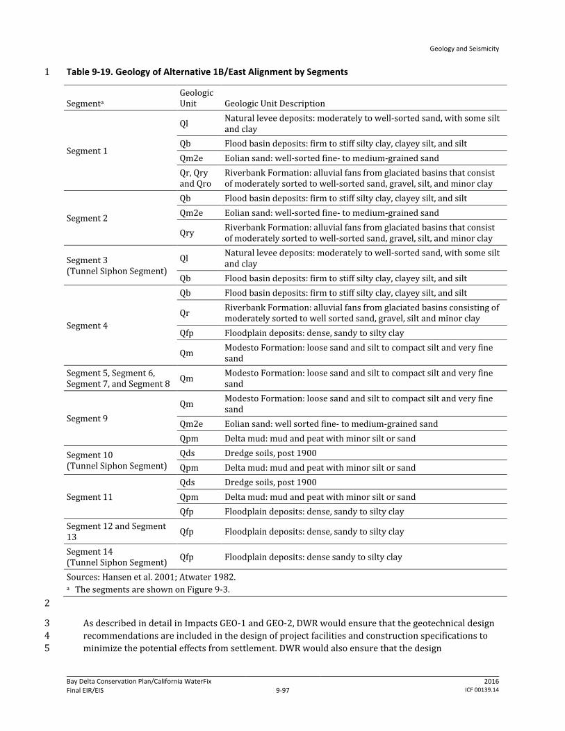
Geology and Seismicity
Bay Delta Conservation Plan/California WaterFix Final EIR/EIS
Administrative Final 9-97
2016 ICF 00139.14
Table 9-19. Geology of Alternative 1B/East Alignment by Segments 1
Segmenta Geologic Unit Geologic Unit Description
Segment 1
Ql Natural levee deposits: moderately to well-sorted sand, with some silt and clay
Qb Flood basin deposits: firm to stiff silty clay, clayey silt, and silt Qm2e Eolian sand: well-sorted fine- to medium-grained sand Qr, Qry and Qro
Riverbank Formation: alluvial fans from glaciated basins that consist of moderately sorted to well-sorted sand, gravel, silt, and minor clay
Segment 2
Qb Flood basin deposits: firm to stiff silty clay, clayey silt, and silt Qm2e Eolian sand: well-sorted fine- to medium-grained sand
Qry Riverbank Formation: alluvial fans from glaciated basins that consist of moderately sorted to well-sorted sand, gravel, silt, and minor clay
Segment 3 (Tunnel Siphon Segment)
Ql Natural levee deposits: moderately to well-sorted sand, with some silt and clay
Qb Flood basin deposits: firm to stiff silty clay, clayey silt, and silt
Segment 4
Qb Flood basin deposits: firm to stiff silty clay, clayey silt, and silt
Qr Riverbank Formation: alluvial fans from glaciated basins consisting of moderately sorted to well sorted sand, gravel, silt and minor clay
Qfp Floodplain deposits: dense, sandy to silty clay
Qm Modesto Formation: loose sand and silt to compact silt and very fine sand
Segment 5, Segment 6, Segment 7, and Segment 8 Qm Modesto Formation: loose sand and silt to compact silt and very fine
sand
Segment 9 Qm Modesto Formation: loose sand and silt to compact silt and very fine
sand Qm2e Eolian sand: well sorted fine- to medium-grained sand Qpm Delta mud: mud and peat with minor silt or sand
Segment 10 (Tunnel Siphon Segment)
Qds Dredge soils, post 1900 Qpm Delta mud: mud and peat with minor silt or sand
Segment 11 Qds Dredge soils, post 1900 Qpm Delta mud: mud and peat with minor silt or sand Qfp Floodplain deposits: dense, sandy to silty clay
Segment 12 and Segment 13 Qfp Floodplain deposits: dense, sandy to silty clay
Segment 14 (Tunnel Siphon Segment) Qfp Floodplain deposits: dense sandy to silty clay
Sources: Hansen et al. 2001; Atwater 1982. a The segments are shown on Figure 9-3. 2
As described in detail in Impacts GEO-1 and GEO-2, DWR would ensure that the geotechnical design 3 recommendations are included in the design of project facilities and construction specifications to 4 minimize the potential effects from settlement. DWR would also ensure that the design 5
Geology and Seismicity
Bay Delta Conservation Plan/California WaterFix Final EIR/EIS
Administrative Final 9-98
2016 ICF 00139.14
specifications are properly executed during construction. DWR has made this conformance and 1 monitoring process an environmental commitment of the BDCP (Appendix 3B, Environmental 2 Commitments, AMMs, and CMs). 3
Generally, the applicable codes require that facilities be built so that they are designed for slope 4 stability and seepage/underseepage factors of safety greater than 1.0 (i.e., stable) and would 5 therefore be less impacted in the event of ground settlement. The worker safety codes and 6 standards specify protective measures that must be taken at construction sites to minimize the risk 7 of injury or death from structural or earth failure. The relevant codes and standards represent 8 performance standards that must be met by contractors and these measures are subject to 9 monitoring by state and local agencies. Cal-OSHA requirements for an IIPP and the terms of the IIPP 10 to protect worker safety are the principal measures that would be enforced at construction sites. 11
Conformance to these and other applicable design specifications and standards would ensure that 12 construction of Alternative 1B would not create an increased likelihood of loss of property, personal 13 injury or death of individuals from ground settlement. Therefore, there would be no adverse effect. 14
CEQA Conclusion: Ground settlement above the tunnel siphon construction could result in loss of 15 property or personal injury during construction. However, DWR would conform to Cal-OSHA, USACE 16 and other design requirements to protect worker safety. DWR would also ensure that the design 17 specifications are properly executed during construction. DWR has made an environmental 18 commitment to use the appropriate code and standard requirements to minimize potential risks 19 (Appendix 3B, Environmental Commitments, AMMs, and CMs). Conformance with these requirements 20 and the application of accepted, proven construction engineering practices would reduce any 21 potential risk such that construction of Alternative 1B would not create an increased likelihood of 22 loss of property, personal injury or death of individuals from ground settlement. This risk would be 23 less than significant. No mitigation is required. 24
Impact GEO-4: Loss of Property, Personal Injury, or Death from Slope Failure during 25 Construction of Water Conveyance Features 26
Excavation of borrow material could result in failure of cut slopes and application of temporary 27 spoils and RTM at storage sites could cause excessive settlement in the spoils, potentially causing 28 injury of workers at the construction sites. Soil and sediment, especially those consisting of loose 29 alluvium and soft peat or mud, would particularly be prone to failure and movement. Additionally, 30 groundwater is expected to be within a few feet of the ground surface in these areas, this may make 31 excavations more prone to failure. 32
Borrow and spoils areas for construction of the canal foundation, intakes, sedimentation basins, 33 pumping plants, forebays, and other supporting facilities would be sited near the locations of these 34 structures (generally within 10 miles). Along the alignment, selected areas would also be used for 35 disposing of the byproduct (RTM) of tunnel siphon construction. Table 9-20 describes the geology of 36 these areas as mapped by Atwater (1982) (Figure 9-3). 37
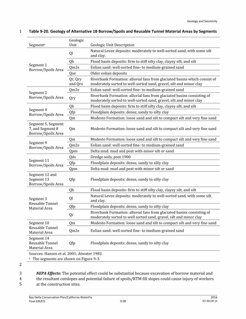
Geology and Seismicity
Bay Delta Conservation Plan/California WaterFix Final EIR/EIS
Administrative Final 9-99
2016 ICF 00139.14
Table 9-20. Geology of Alternative 1B Borrow/Spoils and Reusable Tunnel Material Areas by Segments 1
Segmenta Geologic Unit Geologic Unit Description
Segment 1 Borrow/Spoils Area
Ql Natural Levee deposits: moderately to well-sorted sand, with some silt and clay.
Qb Flood basin deposits: firm to stiff silty clay, clayey silt, and silt Qm2e Eolian sand: well-sorted fine- to medium-grained sand Qoe Older eolian deposits Qr, Qry and Qro
Riverbank Formation: alluvial fans from glaciated basins which consist of moderately sorted to well-sorted sand, gravel, silt and minor clay
Segment 2 Borrow/Spoils Area
Qm2e Eolian sand: well-sorted fine- to medium-grained sand
Qry Riverbank Formation: alluvial fans from glaciated basins consisting of moderately sorted to well-sorted sand, gravel, silt and minor clay
Segment 4 Borrow/Spoils Area
Qb Flood basin deposits: firm to stiff silty clay, clayey silt, and silt Qfp Floodplain deposits: dense, sandy to silty clay Qm Modesto Formation: loose sand and silt to compact silt and very fine sand
Segment 5, Segment 7, and Segment 8 Borrow/Spoils Area
Qm Modesto Formation: loose sand and silt to compact silt and very fine sand
Segment 9 Borrow/Spoils Area
Qm Modesto Formation: loose sand and silt to compact silt and very fine sand Qm2e Eolian sand: well-sorted fine- to medium-grained sand Qpm Delta mud: mud and peat with minor silt or sand
Segment 11 Borrow/Spoils Area
Qds Dredge soils, post 1900 Qfp Floodplain deposits: dense, sandy to silty clay Qpm Delta mud: mud and peat with minor silt or sand
Segment 12 and Segment 13 Borrow/Spoils Area
Qfp Floodplain deposits: dense, sandy to silty clay
Segment 3 Reusable Tunnel Material Area
Qb Flood basin deposits: firm to stiff silty clay, clayey silt, and silt
Ql Natural Levee deposits: moderately to well-sorted sand, with some silt and clay.
Qfp Floodplain deposits: dense, sandy to silty clay
Qr Riverbank Formation: alluvial fans from glaciated basins consisting of moderately sorted to well sorted sand, gravel, silt and minor clay
Segment 10 Reusable Tunnel Material Area
Qm Modesto Formation: loose sand and silt to compact silt and very fine sand
Qm2e Eolian sand: well-sorted fine- to medium-grained sand
Segment 14 Reusable Tunnel Material Area
Qfp Floodplain deposits: dense, sandy to silty clay
Sources: Hansen et al. 2001; Atwater 1982. a The segments are shown on Figure 9-3. 2
NEPA Effects: The potential effect could be substantial because excavation of borrow material and 3 the resultant cutslopes and potential failure of spoils/RTM fill slopes could cause injury of workers 4 at the construction sites. 5
Geology and Seismicity
Bay Delta Conservation Plan/California WaterFix Final EIR/EIS
Administrative Final 9-100
2016 ICF 00139.14
Excavations in borrow areas would be designed to avoid excessive ground movements on adjacent 1 areas and soil “boiling” (i.e., upwelling of groundwater) at the bottom of the excavation. Spoils would 2 be placed in 12-inch lifts with proper compaction and stored no higher than 12 feet above 3 preconstruction ground elevation with maximum side slopes of 5H:1V. During design, the potential 4 for native ground settlement below the spoils would be evaluated by a geotechnical engineer using 5 site-specific geotechnical and hydrological information. The use of shoring, seepage cutoff walls, and 6 ground modifications to prevent slope instability, soil boiling, or excessive settlement would be 7 considered in the design. 8
In addition to the risk of slope failure at borrow sites and spoils and RTM sites, there are also 9 potential impacts on levee stability resulting from construction of Alternative 1B water conveyance 10 facilities. The intakes would be sited along the existing Sacramento River levee system, requiring 11 reconstruction of levees to provide continued flood management. At each intake pumping plant site, 12 a new setback levee (ring levee) would be constructed. The space enclosed by the setback levee 13 would be filled up to the elevation of the top of the setback levee, creating a building pad for the 14 adjacent pumping plant. 15
As discussed in Chapter 3, Description of the Alternatives, the new levees would be designed to 16 provide an adequate Sacramento River channel cross section and to provide the same level of flood 17 protection as the existing levee and would be constructed to geometries that exceed PL 84-99 18 standards. Transition levees would be constructed to connect the existing levees to the new setback 19 levees. A typical new levee would have a broad-based, generally asymmetrical triangular cross 20 section. The levee height considered wind and wave erosion. As measured from the adjacent ground 21 surface on the landside vertically up to the elevation of the levee crest, would range from 22 approximately 20 to 45 feet to provide adequate freeboard above anticipated water surface 23 elevations. The width of the levee (toe of levee to toe of levee) would range from approximately 180 24 to 360 feet. The minimum crest width of the levee would be 20 feet; however, in some places it 25 would be larger to accommodate roadways and other features. Cut-off walls would be constructed to 26 avoid seepage, and the minimum slope of levee walls would be three units horizontal to one unit 27 vertical. All levee reconstruction would conform to applicable state and federal flood management 28 engineering and permitting requirements. 29
Depending on foundation material, foundation improvements would require excavation and 30 replacement of soil below the new levee footprint and potential ground improvement. The levees 31 would be armored with riprap—small to large angular boulders—on the waterside. Intakes would 32 be constructed using a sheetpile cofferdam in the river to create a dewatered construction area that 33 would encompass the intake site. The cofferdam would lie approximately 10–35 feet from the 34 footprint of the intake and would be built from upstream to downstream, with the downstream end 35 closed last. The distance between the face of the intake and the face of the cofferdam would be 36 dependent on the foundation design and overall dimensions. The length of each temporary 37 cofferdam would vary by intake location, but would range from 740 to 2,440 feet. Cofferdams would 38 be supported by steel sheet piles and/or king piles (heavy H-section steel piles). Installation of these 39 piles may require both impact and vibratory pile drivers. Some clearing and grubbing of levees 40 would be required prior to installation of the sheet pile cofferdam, depending on site conditions. 41 Additionally, if stone bank protection, riprap, or mature vegetation is present at intake construction 42 site, it would be removed prior to sheet pile installation. 43

Geology and Seismicity
Bay Delta Conservation Plan/California WaterFix Final EIR/EIS
Administrative Final 9-101
2016 ICF 00139.14
As described in Section 9.3.1, Methods for Analysis, the measures would conform to applicable 1 construction, design and building codes, guidelines, and standards, such as the California Building 2 Code and USACE‘s Engineering and Design—Structural Design and Evaluation of Outlet Works. DWR 3 would ensure that the geotechnical design recommendations are included in the construction and 4 design of project facilities and construction specifications to minimize the potential effects from 5 failure of excavations and settlement. DWR would also ensure that the design specifications are 6 properly executed during construction. 7
In particular, conformance with the following codes and standards would reduce the potential risk 8 for increased likelihood of loss of property or personal injury from settlement/failure of cutslopes of 9 borrow sites and failure of soil or RTM fill slopes during construction. 10
DWR Division of Engineering State Water Project—Seismic Loading Criteria Report, September 11 2012. 12
DWR Division of Flood Management FloodSAFE Urban Levee Design Criteria, May 2012. 13
8 CCR Sections 1509 and 3203. 14
Generally, the applicable codes require that facilities be built to certain factors of safety in order to 15 ensure that facilities perform as designed for the life of the structure despite various soil 16 parameters. The worker safety codes and standards specify protective measures that must be taken 17 at construction sites to minimize the risk of injury or death from structural or earth failure (e.g., 18 utilizing personal protective equipment, practicing crane and scaffold safety measures). The 19 relevant codes and standards represent performance standards that must be met by contractors and 20 these measures are subject to monitoring by state and local agencies. Cal-OSHA requirements for an 21 IIPP and the terms of the IIPP to protect worker safety are the principal measures that would be 22 enforced at construction sites. 23
Conformance to these and other applicable design specifications and standards would ensure that 24 construction of Alternative 1B would not create an increase likelihood of loss of property, personal 25 injury or death of individuals from slope failure at borrow sites and spoils and RTM storage sites. 26 The maintenance and reconstruction of levees would improve levee stability over existing 27 conditions due to improved side slopes, erosion control measures (geotextile fabrics, rock 28 revetments, or other material), seepage reduction measures, and overall mass. Therefore, there 29 would be no adverse effect. 30
CEQA Conclusion: Settlement/failure of cutslopes of borrow sites and failure of soil/RTM fill slopes 31 could result in loss of property or personal injury during construction. However, DWR would 32 conform to Cal-OSHA and other state code requirements and conform to applicable geotechnical 33 design guidelines and standards, such as USACE design measures. Conformance with these 34 requirements and the application of accepted, proven construction engineering practices would 35 reduce any potential risk such that construction of Alternative 1B would not create an increased 36 likelihood of loss of property, personal injury or death of individuals from slope failure at borrow 37 sites and spoils and RTM storage sites. The maintenance and reconstruction of levees would 38 improve levee stability over existing conditions due to improved side slopes, erosion control 39 measures, seepage reduction measures, and overall mass. The impact would be less than significant. 40 No mitigation is required. 41
Geology and Seismicity
Bay Delta Conservation Plan/California WaterFix Final EIR/EIS
Administrative Final 9-102
2016 ICF 00139.14
Impact GEO-5: Loss of Property, Personal Injury, or Death from Structural Failure Resulting 1 from Construction-Related Ground Motions during Construction of Water Conveyance 2 Features 3
Pile driving and other heavy equipment operations would cause vibrations that could initiate 4 liquefaction and associated ground movements in places where soil and groundwater conditions are 5 present to allow liquefaction to occur. The consequences of liquefaction could be manifested in 6 terms of compaction or settlement, loss of bearing capacity, lateral spreading (horizontal soil 7 movement), increased lateral soil pressure, and buoyancy within zones of liquefaction. These 8 consequences could damage nearby structures and levees. 9
The lateral extent (or influenced distance) of damage potential caused by pile driving and heavy 10 equipment operations depends on many factors, including soil conditions, the piling hammer used, 11 frequency of piling, and the vibration tolerance of structures and levees. 12
Pile driving would be conducted at the intakes, where, based on boring logs, soil materials subject to 13 liquefaction (e.g., saturated, poorly graded sand) are present. In addition to pile driving activities, 14 construction of the water conveyance facilities would require an increased volume of truck and 15 heavy equipment traffic that may occur at some of these locations. Although the trucks and heavy 16 equipment could generate vibrations in the levees, the severity of the vibrations is not expected to 17 be capable of initiating liquefaction. Construction related to conveyance facilities would also require 18 regular access to construction sites, extending the length of the project. Some of the existing public 19 roads would be used as haul routes for the construction of conveyance facilities. Use of the state 20 highway system as haul routes would be maximized where feasible because these roadways are 21 rated for truck traffic and would generally provide the most direct and easily maneuverable routes 22 for large loads. As part of future engineering phases, haul routes needed for the construction of the 23 approved project would be refined. Construction traffic may need to access levee roads at various 24 points along State Route (SR) 160 and other state routes as shown in Figure 9-7, as well as at 25 locations shown along the East Alignment in Figure 9-8a. Because of the volume of truck traffic that 26 may occur at some of these locations, there is the potential for some effect on levee integrity at 27 various locations depending on the site specific levee conditions along access routes. 28
During project design, site-specific geotechnical and groundwater investigations would be 29 conducted to build upon existing data (e.g., California Department of Water Resources 2009a, 2010i) 30 to identify and characterize the vertical (depth) and horizontal (spatial) variability in soil bearing 31 capacity and extent of liquefiable soil. Engineering soil parameters that could be used to assess the 32 liquefaction potential, such as SPT blow counts, CPT penetration tip pressure/resistance, and 33 gradation of soil, would also be obtained. SPT blow counts and CPT tip pressure are used to estimate 34 soil resistance to cyclic loadings by using empirical relationships that were developed based on 35 occurrences of liquefaction (or lack of them) during past earthquakes. The resistance then can be 36 compared to cyclic shear stress induced by the design earthquake (i.e., the earthquake that is 37 expected to produce the strongest level of ground shaking at a site to which it is appropriate to 38 design a structure to withstand). If soil resistance is less than induced stress, the potential of having 39 liquefaction during the design earthquakes is high. It is also known that soil with high “fines” (i.e., 40 silt- and clay-sized particles) content are less susceptible to liquefaction. 41
NEPA Effects: The potential effect could be substantial because construction-related ground motions 42 could initiate liquefaction, which could cause failure of structures during construction, which could 43 result in injury of workers at the construction sites. Some of the potential levee effects that could 44
Geology and Seismicity
Bay Delta Conservation Plan/California WaterFix Final EIR/EIS
Administrative Final 9-103
2016 ICF 00139.14
occur during the construction in the absence of corrective measures may include rutting, settlement, 1 and slope movement. 2
During design, the facility-specific potential for liquefaction would be investigated by a geotechnical 3 engineer. The potential effects of construction vibrations on nearby structures, levees, and utilities 4 would be evaluated using specific piling information (such as pile type, length, spacing, and pile-5 driving hammer to be used). In areas determined to have a potential for liquefaction, the California-6 registered civil engineer or California-certified engineering geologist would develop design 7 strategies and construction methods to ensure that pile driving and heavy equipment operations do 8 not damage facilities under construction and surrounding structures and do not threaten the safety 9 of workers at the site. As shown in Figure 9-6, the area from Disappointment Slough to Holt which 10 Alternative 1B crosses through has medium to medium-high potential for levee liquefaction damage. 11 Several siphons and a pumping plant north of Holt are located in this medium to medium-high 12 potential for levee liquefaction damage area. Design measures may include predrilling or jetting, 13 using open-ended pipe piles to reduce the energy needed for pile penetration, using CIDH 14 piles/piers that do not require driving, using pile jacking to press piles into the ground by means of a 15 hydraulic system, or driving piles during the drier summer months. Field data collected during 16 design also would be evaluated to determine the need for and extent of strengthening levees, 17 embankments, and structures to reduce the effect of vibrations. These construction methods would 18 conform to current seismic design codes and requirements, as described in Chapter 3, Description of 19 the Alternatives. Such design standards include USACE‘s Engineering and Design—Stability Analysis 20 of Concrete Structures and Soil Liquefaction during Earthquakes, by the Earthquake Engineering 21 Research Institute. 22
As with the effects related to design of conveyance facilities, potential construction traffic effects on 23 levees would be assessed prior to project construction to determine specific geotechnical issues 24 related to construction traffic loading. Based on the initial assessment from field reconnaissance, 25 geotechnical exploration and analyses would be performed for levee sections that need further 26 evaluations. Should the geotechnical evaluations indicate that certain segments of existing levee 27 roads need improvements to carry the expected construction truck traffic loads, DWR is committed 28 to carry out the necessary improvements to the affected levee sections or to find an alternative route 29 that would avoid the potential deficient levee sections (Mitigation Measures TRANS-2a through 2c). 30 As discussed in Chapter 19, Transportation, Mitigation Measure TRANS-2c, all affected roadways 31 would be returned to preconstruction condition or better following construction. Implementation of 32 this measure would ensure that construction activities would not worsen pavement and levee 33 conditions, relative to existing conditions. Prior to construction, DWR would make a good faith effort 34 to enter into mitigation agreements with or to obtain encroachment permits from affected agencies 35 to verify what the location, extent, timing, and fair share cost to be paid by the DWR for any 36 necessary pre- and post-construction physical improvements. Levee roads that are identified as 37 potential haul routes and expected to carry significant construction truck traffic would be monitored 38 to ensure that truck traffic is not adversely affecting the levee and to identify the need for corrective 39 action. 40
DWR has made the environmental commitment (see Appendix 3B, Environmental Commitments, 41 AMMs, and CMs) that the construction methods recommended by the geotechnical engineer are 42 included in the design of project facilities and construction specifications to minimize the potential 43 for construction-induced liquefaction. DWR also has committed to ensure that these methods are 44 followed during construction. 45

Geology and Seismicity
Bay Delta Conservation Plan/California WaterFix Final EIR/EIS
Administrative Final 9-104
2016 ICF 00139.14
In particular, conformance with the following codes and standards would reduce the potential risk 1 for increased likelihood of loss of property or personal injury from structural failure resulting from 2 construction-related ground motions.: 3
USACE Engineering and Design—Design of Pile Foundations, EM 1110-2-2906, 1991. 4
USACE Engineering and Design—Earthquake Design and Evaluation for Civil Works Projects, 5 ER 1110-2-1806, 1995. 6
8 CCR Sections 1509 and 3203. 7
Generally, the applicable codes require that facilities be built so that if soil in the foundation or 8 surrounding area are subject to liquefaction, the removal or densifaction of the liquefiable material 9 should be considered, along with alternative foundation designs. Additionally, any modification to a 10 federal levee system would require USACE approval under 33 USC 408 (a 408 Permit). 11
The worker safety codes and standards specify protective measures that must be taken at 12 construction sites to minimize the risk of injury or death from structural or earth failure (e.g., 13 utilizing personal protective equipment, practicing crane and scaffold safety measures). The 14 relevant codes and standards represent performance standards that must be met by contractors and 15 these measures are subject to monitoring by state and local agencies. Cal-OSHA requirements for an 16 IIPP and the terms of the IIPP to protect worker safety are the principal measures that would be 17 enforced at construction sites. 18
Conformance to construction methods recommendations and other applicable specifications, as well 19 as implementation of Mitigation Measures TRANS-2a through 2c, would ensure that construction of 20 Alternative 1B would not create an increased likelihood of loss of property, personal injury or death 21 of individuals due to construction- and traffic-related ground motions and resulting potential 22 liquefaction in the work area. The effect would not be adverse. 23
CEQA Conclusion: Construction-related ground motions and traffic effects could initiate 24 liquefaction, which could cause failure of structures during construction, which could result in injury 25 of workers at the construction sites. The impact would be significant. However, DWR has committed 26 to conform to Cal-OSHA and other state code requirements and conform to applicable design 27 guidelines and standards, such as USACE design measures. Conformance with these requirements 28 and the application of accepted, proven construction engineering practices, in addition to 29 implementation of Mitigation Measures TRANS-2a and TRANS-2b, as well as the maintenance and 30 reconstruction of levees through Mitigation Measure TRANS-2c, would reduce any potential risk 31 such that construction of Alternative 1A would not create an increased likelihood of loss of property, 32 personal injury or death of individuals from construction-related ground motion and resulting 33 potential liquefaction in the work area, and the hazard would be controlled to a level that would 34 protect worker safety (see Appendix 3B, Environmental Commitments, AMMs, and CMs). The impact 35 would be less than significant. 36
Mitigation Measure TRANS-2a: Prohibit Construction Activity on Physically Deficient 37 Roadway Segments 38
Please refer to Mitigation Measure TRANS-2a in Alternative 1A, Impact TRANS-2, in Chapter 19, 39 Transportation. 40
Geology and Seismicity
Bay Delta Conservation Plan/California WaterFix Final EIR/EIS
Administrative Final 9-105
2016 ICF 00139.14
Mitigation Measure TRANS-2b: Limit Construction Activity on Physically Deficient 1 Roadway Segments 2
Please refer to Mitigation Measure TRANS-2b in Alternative 1A, Impact TRANS-2, in Chapter 19, 3 Transportation. 4
Mitigation Measure TRANS-2c: Improve Physical Condition of Affected Roadway Segments 5 as Stipulated in Mitigation Agreements or Encroachment Permits 6
Please refer to Mitigation Measure TRANS-2c in Alternative 1A, Impact TRANS-2, in Chapter 19, 7 Transportation. 8
Impact GEO-6: Loss of Property, Personal Injury, or Death from Structural Failure Resulting 9 from Rupture of a Known Earthquake Fault during Operation of Water Conveyance Features 10
According to the available AP Earthquake Fault Zone Maps, none of the Alternative 1B facilities 11 would cross or be within any known active fault zones. However, numerous AP fault zones have 12 been mapped west of the conveyance alignment (Figure 9-5). The closest AP fault zone would be the 13 Greenville fault, located approximately 13 miles west of the Alternative 1B conveyance alignment. 14 Because none of the Alternative 1B constructed facilities would be within any of the fault zones 15 (which include the area approximately 200 to 500 feet on each side of the mapped surface trace to 16 account for potential branches of active faults), the potential that the facilities would be directly 17 subject to fault offsets is negligible. 18
In the Delta, active or potentially active blind thrust faults were identified in the seismic study. 19 Segments 2, 3, 4, and 5 of Alternative 1B conveyance alignment would cross the Thornton Arch fault 20 zone. The western part of the proposed Byron Tract Forebay adjacent to the Clifton Court Forebay is 21 underlain by the West Tracy fault. Although these blind thrusts are not expected to rupture to the 22 ground surface under the forebays during earthquake events, they may produce ground or 23 near-ground shear zones, bulging, or both (California Department of Water Resources 2007a). 24 Assuming that the West Tracy fault is potentially active, it could cause surface deformation in the 25 western part of the Clifton Court Forebay. Because the western part of the Byron Tract Forebay is 26 also underlain by the hanging wall of the fault, this part of the forebay may also experience uplift 27 and resultant surface deformation (Fugro Consultants 2011). In the seismic study (California 28 Department of Water Resources 2007a), the Thornton Arch and West Tracy blind thrusts have been 29 assigned 20% and 90% probabilities of being active, respectively. The depth to the Thornton Arch 30 blind thrust is unknown. The seismic study indicates that the West Tracy fault dies out as a 31 discernible feature within approximately 3,000 to 6,000 feet bgs (in the upper 1 to 2 second depth 32 two-way time, estimated to be approximately 3,000 to 6,000 feet using the general velocity function 33 as published in the Association of Petroleum Geologists Pacific Section newsletter [Tolmachoff 34 1993]). 35
It appears that the potential of having any shear zones, bulging, or both at the depths of the tunnel 36 siphons is low because the depth to the blind thrust faults is generally deep. 37
NEPA Effects: The effect would not be adverse because no active faults capable of surface rupture 38 extend into the Alternative 1B alignment. Additionally, although the Thornton Arch and West Tracy 39 blind thrusts occur beneath the Alternative 1B alignment, based on available information, they do 40 not present a hazard of surface rupture. 41

Geology and Seismicity
Bay Delta Conservation Plan/California WaterFix Final EIR/EIS
Administrative Final 9-106
2016 ICF 00139.14
However, because of the limited information regarding the depths of the Thornton Arch and West 1 Tracy blind thrusts, seismic surveys would be performed on the faults during the design phase to 2 determine the depths to the top of the faults. More broadly, design-level geotechnical studies would 3 be prepared by a geotechnical engineer licensed in the state of California during project design. The 4 studies would further assess site-specific conditions at and near all the project facility locations, 5 including seismic activity, soil liquefaction, and other potential geologic and soil-related hazards. 6 This information would be used to verify assumptions and conclusions included in the EIR/EIS. The 7 geotechnical engineer’s recommended measures to address adverse conditions would conform to 8 applicable design codes, guidelines, and standards. Potential design strategies or conditions could 9 include avoidance (deliberately positioning structures and lifelines to avoid crossing identified 10 shear rupture zones), geotechnical engineering (using the inherent capability of unconsolidated 11 geomaterials to “locally absorb” and distribute distinct bedrock fault movements) and structural 12 engineering (engineering the facility to undergo some limited amount of ground deformation 13 without collapse or significant damage). 14
As described in Section 9.3.1, Methods for Analysis, such design codes, guidelines, and standards are 15 environmental commitments by DWR (see also Appendix 3B, Environmental Commitments, AMMs, 16 and CMs). For construction of the water conveyance facilities, the codes and standards would 17 include the California Building Code and resource agency and professional engineering 18 specifications, such as the Division of Safety of Dams Guidelines for Use of the Consequence-Hazard 19 Matrix and Selection of Ground Motion Parameters, DWR’s Division of Flood Management FloodSAFE 20 Urban Levee Design Criteria, and USACE‘s Engineering and Design—Earthquake Design and 21 Evaluation for Civil Works Projects. These codes and standards include minimum performance 22 standards for structural design, given site-specific subsurface conditions. 23
DWR would ensure that the geotechnical design recommendations are included in the design of 24 project facilities and construction specifications to minimize the potential effects from seismic 25 events and the presence of adverse soil conditions. DWR would also ensure that the design 26 specifications are properly executed during construction. 27
In particular, conformance with the following codes and standards would reduce the potential risk 28 for increased likelihood of loss of property or personal injury from structural failure resulting from 29 surface rupture resulting from a seismic event during operation. 30
DWR Division of Engineering State Water Project—Seismic Loading Criteria Report, September 31 2012. 32
USACE Engineering and Design—Time-History Dynamic Analysis of Concrete Hydraulic Structures, 33 EM 1110-2-6051, 2003. 34
USACE Engineering and Design—Response Spectra and Seismic Analysis for Concrete Hydraulic 35 Structures, EM 1110-2-6050, 1999. 36
American Society of Civil Engineers Minimum Design Loads for Buildings and Other Structures, 37 ASCE/SEI 7-10, 2010. 38
8 CCR 3203. 39
Generally, the applicable codes require that facilities be built so that they incur minimal damage in 40 the event of a foreseeable seismic event and that they remain functional following such an event and 41 that the facility is able to perform without catastrophic failure in the event of a maximum design 42
Geology and Seismicity
Bay Delta Conservation Plan/California WaterFix Final EIR/EIS
Administrative Final 9-107
2016 ICF 00139.14
earthquake (the greatest earthquake reasonably expected to be generated by a specific source on 1 the basis of seismological and geological evidence). 2
The worker safety codes and standards specify protective measures that must be taken at 3 workplaces to minimize the risk of injury or death from structural or earth failure (e.g., utilizing 4 personal protective equipment). The relevant codes and standards represent performance 5 standards that must be met by employers and these measures are subject to monitoring by state and 6 local agencies. Cal-OSHA requirements for an IIPP and the terms of the IIPP to protect worker safety 7 are the principal measures that would be enforced at workplaces. 8
Conformance to these and other applicable design specifications and standards would ensure that 9 operation of Alternative 1B would not create an increased likelihood of loss of property, personal 10 injury or death of individuals in the event of ground movement in the vicinity of the Thornton Arch 11 fault zone and would not jeopardize the integrity of the surface and subsurface facilities along the 12 Alternative 1B conveyance alignment or the proposed forebay and associated facilities adjacent to 13 the Clifton Court Forebay. Therefore, there would be no adverse effect. 14
CEQA Conclusion: There are no active fault capable of surface rupture that extend into the 15 Alternative 1B alignment. Although the Thornton Arch and West Tracy blind thrusts occur beneath 16 the Alternative 1B alignment, based on available information, they do not present a hazard of 17 surface rupture. Conformance to applicable design specifications and standards would ensure that 18 operation of Alternative 1B would not create an increased likelihood of loss of property, injury or 19 death of individuals in the event of ground movement in the vicinity of the Thornton Arch fault zone 20 or West Tracy blind thrusts and would not jeopardize the integrity of the surface and subsurface 21 facilities along the Alternative 1B conveyance alignment or the proposed forebay and associated 22 facilities adjacent to the Clifton Court Forebay. There would be no impact. No mitigation is required. 23
Impact GEO-7: Loss of Property, Personal Injury, or Death from Structural Failure Resulting 24 from Strong Seismic Shaking during Operation of Water Conveyance Features 25
Earthquake events may occur on the local and regional seismic sources during operation of the 26 Alternative 1B water conveyance facilities. The ground shaking could damage the canals, pipelines, 27 tunnel and culvert siphons, intake facilities, pumping plants, and other facilities, disrupting the 28 water supply through the conveyance system. In an extreme event of strong seismic shaking, 29 uncontrolled release of water from the damaged canal, pipelines, tunnel siphons, intake facilities, 30 pumping plants, and other facilities could cause flooding, disruption of water supplies to the south, 31 and inundation of structures. These effects are discussed more fully in Appendix 3E, Potential 32 Seismicity and Climate Change Risks to SWP/CVP Water Supplies. The potential of earthquake ground 33 shaking in the early long-term (2025) was estimated using the results of the seismic study 34 (California Department of Water Resources 2007a). Table 9-21 lists the expected PGA and 1.0-Sa 35 values for early long-term. Earthquake ground shakings for the OBE (144-year return period) and 36 MDE (975-year return period) were estimated for the stiff soil site, as predicted in the seismic study 37 (California Department of Water Resources 2007a), and for the anticipated soil conditions at the 38 facility locations. No seismic study results exist for 2025, so the ground shakings estimated for 2050 39 were used for early long-term. 40
Table 9-21 shows that the proposed facilities would be subject to moderate-to-high earthquake 41 ground shakings in the Early Long-term through 2025. All facilities would be designed and 42 constructed in accordance with the requirements of the design measures described in Appendix 3B, 43 Environmental Commitments, AMMs, and CMs. Site-specific geotechnical information would be used 44
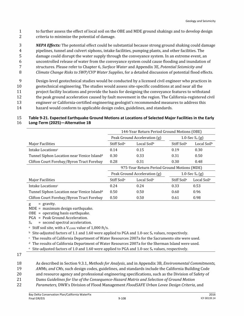
Geology and Seismicity
Bay Delta Conservation Plan/California WaterFix Final EIR/EIS
Administrative Final 9-108
2016 ICF 00139.14
to further assess the effect of local soil on the OBE and MDE ground shakings and to develop design 1 criteria to minimize the potential of damage. 2
NEPA Effects: The potential effect could be substantial because strong ground shaking could damage 3 pipelines, tunnel and culvert siphons, intake facilities, pumping plants, and other facilities. The 4 damage could disrupt the water supply through the conveyance system. In an extreme event, an 5 uncontrolled release of water from the conveyance system could cause flooding and inundation of 6 structures. Please refer to Chapter 6, Surface Water and Appendix 3E, Potential Seismicity and 7 Climate Change Risks to SWP/CVP Water Supplies, for a detailed discussion of potential flood effects. 8
Design-level geotechnical studies would be conducted by a licensed civil engineer who practices in 9 geotechnical engineering. The studies would assess site-specific conditions at and near all the 10 project facility locations and provide the basis for designing the conveyance features to withstand 11 the peak ground acceleration caused by fault movement in the region. The California-registered civil 12 engineer or California-certified engineering geologist’s recommended measures to address this 13 hazard would conform to applicable design codes, guidelines, and standards. 14
Table 9-21. Expected Earthquake Ground Motions at Locations of Selected Major Facilities in the Early 15 Long-Term (2025)—Alternative 1B 16
Major Facilities
144-Year Return Period Ground Motions (OBE) Peak Ground Acceleration (g)
1.0-Sec Sa (g)
Stiff Soila Local Soilb Stiff Soila Local Soilb Intake Locationsc 0.14 0.15 0.19 0.30 Tunnel Siphon Location near Venice Islandd 0.30 0.33 0.31 0.50 Clifton Court Forebay/Byron Tract Forebay 0.28 0.31 0.30 0.48
Major Facilities
975-Year Return Period Ground Motions (MDE) Peak Ground Acceleration (g)
1.0-Sec Sa (g)
Stiff Soila Local Soile Stiff Soila Local Soile Intake Locationsc 0.24 0.24 0.33 0.53 Tunnel Siphon Location near Venice Islandd 0.50 0.50 0.60 0.96 Clifton Court Forebay/Byron Tract Forebay 0.50 0.50 0.61 0.98 g = gravity. MDE = maximum design earthquake. OBE = operating basis earthquake. PGA = Peak Ground Acceleration. Sa = second spectral acceleration. a Stiff soil site, with a Vs100ft value of 1,000 ft/s. b Site-adjusted factors of 1.1 and 1.60 were applied to PGA and 1.0-sec Sa values, respectively. c The results of California Department of Water Resources 2007a for the Sacramento site were used. d The results of California Department of Water Resources 2007a for the Sherman Island were used. e Site-adjusted factors of 1.0 and 1.60 were applied to PGA and 1.0-sec Sa values, respectively. 17
As described in Section 9.3.1, Methods for Analysis, and in Appendix 3B, Environmental Commitments, 18 AMMs, and CMs, such design codes, guidelines, and standards include the California Building Code 19 and resource agency and professional engineering specifications, such as the Division of Safety of 20 Dams Guidelines for Use of the Consequence-Hazard Matrix and Selection of Ground Motion 21 Parameters, DWR‘s Division of Flood Management FloodSAFE Urban Levee Design Criteria, and 22
Geology and Seismicity
Bay Delta Conservation Plan/California WaterFix Final EIR/EIS
Administrative Final 9-109
2016 ICF 00139.14
USACE‘s Engineering and Design—Earthquake Design and Evaluation for Civil Works Projects. 1 Conformance with these codes and standards is an environmental commitment by DWR to ensure 2 that ground shaking risks are minimized as the water conveyance features are operated. 3
DWR would ensure that the geotechnical design recommendations are included in the design of 4 project facilities and construction specifications to minimize the potential effects from seismic 5 events and the presence of adverse soil conditions. DWR would also ensure that the design 6 specifications are properly executed during construction. See Appendix 3B, Environmental 7 Commitments, AMMs, and CMs. 8
In particular, conformance with the following codes and standards would reduce the potential risk 9 for increased likelihood of loss of property or personal injury from structural failure resulting from 10 strong seismic shaking of water conveyance features during operations. 11
DWR Division of Engineering State Water Project—Seismic Loading Criteria Report, September 12 2012. 13
USACE Engineering and Design—Time-History Dynamic Analysis of Concrete Hydraulic Structures, 14 EM 1110-2-6051, 2003. 15
USACE Engineering and Design—Response Spectra and Seismic Analysis for Concrete Hydraulic 16 Structures, EM 1110-2-6050, 1999. 17
American Society of Civil Engineers Minimum Design Loads for Buildings and Other Structures, 18 ASCE/SEI 7-10, 2010. 19
8 CCR 3203. 20
Generally, the applicable codes require that facilities be built so that they incur minimal damage in 21 the event of a foreseeable seismic event and that they remain functional following such an event and 22 that the facility is able to perform without catastrophic failure in the event of a maximum design 23 earthquake (the greatest earthquake reasonably expected to be generated by a specific source on 24 the basis of seismological and geological evidence). 25
Conformance with these standards and codes are an environmental commitment of the project (see 26 Appendix 3B, Environmental Commitments, AMMs, and CMs). The worker safety codes and standards 27 specify protective measures that must be taken at workplaces to minimize the risk of injury or death 28 from structural or earth failure (e.g., utilizing personal protective equipment). The relevant codes 29 and standards represent performance standards that must be met by employers and these measures 30 are subject to monitoring by state and local agencies. Cal-OSHA requirements for an IIPP and the 31 terms of the IIPP to protect worker safety are the principal measures that would be enforced at 32 workplaces during operations. 33
Conformance to these and other applicable design specifications and standards would ensure that 34 operation of Alternative 1B would not create an increased likelihood of loss of property, personal 35 injury or death of individuals from strong seismic shaking of surface and subsurface facilities along 36 the Alternative 1B conveyance alignment. Therefore, there would be no adverse effect. 37
CEQA Conclusion: Seismically induced strong ground shaking could damage the canals, pipelines, 38 tunnel and culvert siphons, intake facilities, pumping plants, and other facilities. The damage could 39 disrupt SWP and CVP water supply deliveries through the conveyance system. In an extreme event, 40 an uncontrolled release of water from the damaged conveyance system could cause flooding and 41 inundation of structures. (Please refer to Appendix 3E, Potential Seismicity and Climate Change Risks 42
Geology and Seismicity
Bay Delta Conservation Plan/California WaterFix Final EIR/EIS
Administrative Final 9-110
2016 ICF 00139.14
to SWP/CVP Water Supplies, for a detailed discussion of potential flood impacts.) However, through 1 the final design process, measures to address this hazard would be required to conform to 2 applicable design codes, guidelines, and standards. As described in Section 9.3.1, Methods for 3 Analysis, and in Appendix 3B, Environmental Commitments, AMMs, and CMs, such design codes, 4 guidelines, and standards include the California Building Code and resource agency and professional 5 engineering specifications, such as the Division of Safety of Dams’ Guidelines for Use of the 6 Consequence-Hazard Matrix and Selection of Ground Motion Parameters, DWR‘s Division of Flood 7 Management FloodSAFE Urban Levee Design Criteria, and USACE‘s Engineering and Design—8 Earthquake Design and Evaluation for Civil Works Projects. Conformance with these codes and 9 standards is an environmental commitment by DWR to ensure that ground shaking risks are 10 minimized as the Alternative 1B water conveyance features are operated and there would be no 11 increased likelihood of loss of property, personal injury or death of individuals. The hazard would be 12 controlled to a safe level. The impact would be less than significant. No mitigation is required. 13
Impact GEO-8: Loss of Property, Personal Injury, or Death from Structural Failure Resulting 14 from Seismic-Related Ground Failure (Including Liquefaction) during Operation of Water 15 Conveyance Features 16
Earthquake-induced ground shaking could cause liquefaction, resulting soil slumping or lateral 17 spreading and subsequent damage to or breaching of water conveyance structures and facilities. The 18 consequences of liquefaction are manifested in terms of compaction or settlement, loss of bearing 19 capacity, lateral spreading (soil movement), increased lateral soil pressure, and buoyancy within 20 zones of liquefaction. Failure of the canal, tunnel and culvert siphons, pipelines, levees, bridges, and 21 other structures and facilities could result in loss or injury and disrupt SWP and CVP water supply 22 deliveries. The potential for impacts from flooding as a result of levee or dam failure is also 23 discussed in Chapter 6, Surface Water. 24
The native soils underlying Alternative 1B facilities consist of floodplain, natural levee, eolian sand, 25 and flood basin deposits, along with more consolidated Modesto Formation materials locally. The 26 more recently deposited, sandy materials would be more prone to liquefaction. Figure 9-6 shows 27 that the Alternative 1B alignment has no substantial liquefaction damage potential in its northern 28 part and low to medium-high damage potential in its central and southern parts from 29 Disappointment Slough down to the proposed Byron Tract Forebay. 30
NEPA Effects: The potential effect could be substantial because seismically induced ground shaking 31 could cause liquefaction, which could result in damage to the canals, pipelines, tunnel and culvert 32 siphons, intake facilities, pumping plants, and other facilities. The damage could disrupt the water 33 supply through the conveyance system. In an extreme event, an uncontrolled release of water from 34 the damaged conveyance system could cause flooding and inundation of structures. Please refer to 35 Appendix 3E, Potential Seismicity and Climate Change Risks to SWP/CVP Water Supplies, for a 36 detailed discussion of potential flood effects. 37
In the process of preparing final facility designs, site-specific geotechnical and groundwater 38 investigations would be conducted to identify and characterize the vertical (depth) and horizontal 39 (spatial) extents of liquefiable soil. Engineering soil parameters that could be used to further assess 40 the liquefaction potential, such as SPT blow counts, CPT penetration tip pressure/resistance, and 41 gradation of soil, would also be obtained. SPT blow counts and CPT tip pressure are used to estimate 42 soil resistance to cyclic loadings by using empirical relationships that were developed based on 43 occurrences of liquefaction (or lack of them) during past earthquakes. The resistance then can be 44
Geology and Seismicity
Bay Delta Conservation Plan/California WaterFix Final EIR/EIS
Administrative Final 9-111
2016 ICF 00139.14
compared to cyclic shear stress induced by the design earthquakes. If soil resistance is less than 1 induced stress, the potential of having liquefaction during the design earthquakes is high. It is also 2 known that soil with high “fines” (i.e., silt- and clay-sized particles) content are less susceptible to 3 liquefaction. 4
During final design, site-specific potential for liquefaction would be investigated by a geotechnical 5 engineer. In areas determined to have a potential for liquefaction, a California-registered civil 6 engineer or California-certified engineering geologist would develop design measures and 7 construction methods to meet design criteria established by building codes and construction 8 standards to ensure that the design earthquake does not cause damage to or failure of the facility. 9 Such measures and methods include removing and replacing potentially liquefiable soil, 10 strengthening foundations (for example, and using post-tensioned slab, reinforced mats, and piles) 11 to resist excessive total and differential settlements, using in situ ground improvement techniques 12 (such as deep dynamic compaction, vibro-compaction, vibro-replacement, compaction grouting, and 13 other similar methods). The results of the site-specific evaluation and California-registered civil 14 engineer or California-certified engineering geologist’s recommendations would be documented in a 15 detailed geotechnical report prepared in accordance with state guidelines, in particular Guidelines 16 for Evaluating and Mitigating Seismic Hazards in California (California Geological Survey 2008). As 17 described in Section 9.3.1, Methods for Analysis, and in Appendix 3B, Environmental Commitments, 18 AMMs, and CMs, such design codes, guidelines, and standards include USACE‘s Engineering and 19 Design—Earthquake Design and Evaluation for Civil Works Projects and Soil Liquefaction during 20 Earthquakes, by the Earthquake Engineering Research Institute. Conformance with these design 21 requirements is an environmental commitment by DWR to ensure that liquefaction risks are 22 minimized as the water conveyance features are operated. 23
DWR would ensure that the geotechnical design recommendations are included in the design of 24 project facilities and construction specifications to minimize the potential effects from liquefaction 25 and associated hazard. DWR would also ensure that the design specifications are properly executed 26 during construction. 27
In particular, conformance with the following codes and standards would reduce the potential risk 28 for increased likelihood of loss of property or personal injury from structural failure resulting from 29 strong seismic shaking of water conveyance features during operations. 30
DWR Division of Engineering State Water Project—Seismic Loading Criteria Report, September 31 2012. 32
USACE Engineering and Design—Time-History Dynamic Analysis of Concrete Hydraulic Structures, 33 EM 1110-2-6051, 2003. 34
USACE Engineering and Design—Response Spectra and Seismic Analysis for Concrete Hydraulic 35 Structures, EM 1110-2-6050, 1999. 36
American Society of Civil Engineers Minimum Design Loads for Buildings and Other Structures, 37 ASCE/SEI 7-10, 2010. 38
USACE Engineering and Design—Design of Pile Foundations, EM 1110-2-2906, 1991 39
8 CCR 3203. 40
Generally, the applicable codes require that facilities be built so that if soil in the foundation or 41 surrounding area are subject to liquefaction, the removal or densifaction of the liquefiable material 42

Geology and Seismicity
Bay Delta Conservation Plan/California WaterFix Final EIR/EIS
Administrative Final 9-112
2016 ICF 00139.14
should be considered, along with alternative foundation designs. Additionally, any modification to a 1 federal levee system would require USACE approval under 33 USC 408 (a 408 Permit). 2
The worker safety codes and standards specify protective measures that must be taken at 3 workplaces to minimize the risk of injury or death from structural or earth failure (e.g., utilizing 4 personal protective equipment). The relevant codes and standards represent performance 5 standards that must be met by employers and these measures are subject to monitoring by state and 6 local agencies. Cal-OSHA requirements for an IIPP and the terms of the IIPP to protect worker safety 7 are the principal measures that would be enforced at workplaces during operations. 8
Conformance to these and other applicable design specifications and standards would ensure that 9 the hazard of liquefaction and associated ground movements would not create an increased 10 likelihood of loss of property, personal injury or death of individuals from structural failure 11 resulting from seismic-related ground failure along the Alternative 1B conveyance alignment during 12 operation of the water conveyance features. Therefore, the effect would not be adverse. 13
CEQA Conclusion: Seismically induced ground shaking could cause liquefaction. Liquefaction could 14 damage the canals, pipelines, tunnel and culvert siphons, intake facilities, pumping plants, and other 15 facilities, and thereby disrupt the water supply through the conveyance system. In an extreme event, 16 flooding and inundation of structures could result from an uncontrolled release of water from the 17 damaged conveyance system. (Please refer to Chapter 6, Surface Water, for a detailed discussion of 18 potential flood effects.) However, through the final design process, measures to address the 19 liquefaction hazard would be required to conform to applicable design codes, guidelines, and 20 standards. As described in Section 9.3.1, Methods for Analysis, and in Appendix 3B, Environmental 21 Commitments, AMMs, and CMs, such design codes, guidelines, and standards include USACE‘s 22 Engineering and Design—Stability Analysis of Concrete Structures and Soil Liquefaction during 23 Earthquakes, by the Earthquake Engineering Research Institute. Conformance with these design 24 standards is an environmental commitment by DWR to ensure that liquefaction risks are minimized 25 as the Alternative 1B water conveyance features are operated and there would be no increased 26 likelihood of loss of property, personal injury or death of individuals. The hazard would be 27 controlled to a safe level. The impact would be less than significant. No mitigation is required. 28
Impact GEO-9: Loss of Property, Personal Injury, or Death from Landslides and Other Slope 29 Instability during Operation of Water Conveyance Features 30
Alternative 1B would involve excavation that creates new cut-and-fill slopes and construction of 31 new embankments and levees. As a result of ground shaking and high soil-water content during 32 heavy rainfall, existing and new slopes that are not properly engineered and natural stream banks 33 could fail. Levees can fail for several reasons: 1) high velocities of water flow can result in high rates 34 of erosion and erode and overtop a levee; 2) the higher velocities of water flow can also lead to 35 higher rates of erosion along the inner parts of levees and lead to undercutting and clumping of the 36 levee into the river. Heavy rainfall or seepage into the levee from the river can increase fluid 37 pressure in the levee and lead to slumping on the outer parts of the levee. If the slumps grow to the 38 top of the levee, large sections of the levee may slump onto the floodplain and lower the elevation of 39 the top of the levee, leading to overtopping; 3) increasing levels of water in the river will cause the 40 water table in the levee to rise which will increase fluid pressure and may result in seepage and 41 eventually lead to internal erosion called piping. Piping will erode the material under the levee, 42 undermining it and causing its collapse and failure. 43

Geology and Seismicity
Bay Delta Conservation Plan/California WaterFix Final EIR/EIS
Administrative Final 9-113
2016 ICF 00139.14
With the exception of levee slopes and natural stream banks, the topography along the Alternative 1 1B conveyance alignment is nearly level to very gently sloping. The areas susceptible to slope failure 2 are along existing levee slopes and at intake, pumping plant, forebay, and certain access road 3 locations. Outside these areas, the land is nearly level and consequently has a negligible potential for 4 slope failure. 5
Based on review of topographic maps, the conveyance facilities would not be constructed on, nor 6 would it be adjacent to, slopes that are subject to mudflows/debris flows from natural slopes. 7
NEPA Effects: The potential effect could be substantial because levee slopes and stream banks may 8 fail, either from high pore-water pressure caused by high rainfall and weak soil, or from seismic 9 shaking. Structures constructed on these slopes could be damaged or fail entirely as a result of slope 10 instability. As discussed in Impact SW-2 in Chapter 6, Surface Water, operation of the water 11 conveyance features under Alternative 1B would not result in an increase in potential risk for flood 12 management compared to existing conditions. Peak monthly flows under Alternative 1B in the 13 locations considered were similar to or less than those that would occur under existing conditions. 14 Since flows would not be substantially greater, the potential for increased rates of erosion or 15 seepage are low. For additional discussion on the possible exposure of people or structures to a 16 significant risk of loss or injury from flooding due to levee failure, please refer to Impact SW-6 in 17 Chapter 6, Surface Water. 18
During project design, a geotechnical engineer would develop slope stability design criteria (such as 19 minimum slope safety factors and allowable slope deformation and settlement) for the various 20 anticipated loading conditions. The design criteria would be documented in a detailed geotechnical 21 report prepared in accordance with state guidelines, in particular Guidelines for Evaluating and 22 Mitigating Seismic Hazards in California (California Geological Survey 2008). As discussed in Chapter 23 3, Description of the Alternatives, the foundation soil beneath slopes, embankments, or levees could 24 be improved to increase its strength and to reduce settlement and deformation. Foundation soil 25 improvement could involve excavation and replacement with engineered fill; preloading; ground 26 modifications using jet-grouting, compaction grouting, chemical grouting, shallow soil mixing, deep 27 soil mixing, vibro-compaction, or vibro-replacement; or other methods. Engineered fill also would 28 be used to construct new slopes, embankments, and levees. Surface and internal drainage systems 29 would be installed as necessary to reduce erosion and piping (internal erosion) potential. 30
Site-specific geotechnical and hydrological information would be used, and the design would 31 conform to the current standards and construction practices, as described in Section 9.3.1, Methods 32 for Analysis, such as USACE‘s Design and Construction of Levees and USACE’s EM 1110-2-1902, Slope 33 Stability. The design requirements would be presented in a detailed geotechnical report. 34 Conformance with these design requirements is an environmental commitment by DWR to ensure 35 that slope stability hazards would be avoided as the water conveyance features are operated. 36
DWR would ensure that the geotechnical design recommendations are included in the design of cut 37 and fill slopes, embankments, and levees to minimize the potential effects from slope failure. DWR 38 would also ensure that the design specifications are properly executed during construction. 39
In particular, conformance with the following codes and standards would reduce the potential risk 40 for increased likelihood of loss of property or personal injury from structural failure resulting from 41 seismic shaking or from high-pore water pressure. 42
Geology and Seismicity
Bay Delta Conservation Plan/California WaterFix Final EIR/EIS
Administrative Final 9-114
2016 ICF 00139.14
DWR Division of Engineering State Water Project—Seismic Loading Criteria Report, September 1 2012. 2
DWR Division of Flood Management FloodSAFE Urban Levee Design Criteria, May 2012. 3
USACE Slope Stability, EM 1110-2-1902, 2003. 4
8 CCR 3203. 5
Generally, the applicable codes require that facilities be built to certain factors of safety in order to 6 ensure that facilities perform as designed for the life of the structure despite various soil 7 parameters. 8
The worker safety codes and standards specify protective measures that must be taken at 9 workplaces to minimize the risk of injury or death from structural or earth failure (e.g., utilizing 10 personal protective equipment). The relevant codes and standards represent performance 11 standards that must be met by employers and these measures are subject to monitoring by state and 12 local agencies. Cal-OSHA requirements for an IIPP and the terms of the IIPP to protect worker safety 13 are the principal measures that would be enforced at workplaces during operations. 14
Conformance to the above and other applicable design specifications and standards would ensure 15 that the hazard of slope instability would not create an increased likelihood of loss of property or 16 injury of individuals along the Alternative 1B conveyance alignment during operation of the water 17 conveyance features. Therefore, the effect would not be adverse. 18
CEQA Conclusion: Unstable levee slopes and natural stream banks may fail, either from high pore-19 water pressure caused by high rainfall and weak soil, or from seismic shaking. Structures 20 constructed on these slopes could be damaged or fail entirely as a result of slope instability. 21 However, through the final design process, measures to address this hazard would be required to 22 conform to applicable design codes, guidelines, and standards. The measures would be described in 23 a detailed geotechnical report prepared in accordance with state guidelines, in particular Guidelines 24 for Evaluating and Mitigating Seismic Hazards in California (California Geological Survey 2008). As 25 described in Section 9.3.1, Methods for Analysis, and in Appendix 3B, Environmental Commitments, 26 AMMs, and CMs, such design codes, guidelines, and standards include the California Building Code 27 and resource agency and professional engineering specifications, such as USACE‘s Engineering and 28 Design—Earthquake Design and Evaluation for Civil Works Projects. Conformance with these codes 29 and standards is an environmental commitment by DWR to ensure cut and fill slopes and 30 embankments would be stable as the Alternative 1B water conveyance features are operated and 31 there would be no increased likelihood of loss of property, personal injury or death of individuals. 32 The impact would be less than significant. No mitigation is required. 33
Impact GEO-10: Loss of Property, Personal Injury, or Death from Seiche or Tsunami during 34 Operation of Water Conveyance Features 35
Based on recorded tsunami wave heights at the Golden Gate (Contra Costa Transportation Agency 36 2009) and in the interior of the San Francisco Bay and on tsunami inundation maps prepared by the 37 California Department of Conservation (2009), the height of a tsunami wave reaching the Suisun 38 Marsh and the Delta would be small because of the distance from the ocean and attenuating effect of 39 the San Francisco Bay. Therefore, the potential hazard of loss of property or personal injury as a 40 result of a tsunami on the water conveyance facilities is low. 41

Geology and Seismicity
Bay Delta Conservation Plan/California WaterFix Final EIR/EIS
Administrative Final 9-115
2016 ICF 00139.14
Similarly, with the exception of the Clifton Court Forebay and the Byron Tract Forebay, the potential 1 for a substantial seiche to take place in the Plan Area is considered low because seismic and water 2 body geometry conditions for a seiche to occur near conveyance facilities are not favorable. Fugro 3 Consultants, Inc. (2011) identified the potential for a seiche of an unspecified wave height to occur 4 in the Clifton Court Forebay, caused by strong ground motions along the underlying West Tracy 5 fault, assuming that this fault is potentially active. Since the fault also exists in the immediate vicinity 6 of the Byron Tract Forebay, a seiche could also occur in the Byron Tract Forebay. 7
NEPA Effects: The effect of a tsunami generated in the Pacific Ocean would not be adverse because 8 the distance from the ocean and attenuating effect of the San Francisco Bay would likely allow only a 9 low (i.e., less than 2 feet) tsunami wave height to reach the Delta (Contra Costa Transportation 10 Agency 2009). 11
In most parts of the Plan Area, the effects of a seiche would not be adverse because the seismic 12 hazard and the geometry of the water bodies (i.e., wide and shallow) near conveyance facilities are 13 not favorable for a seiche to occur. However, assuming that the West Tracy fault is potentially active, 14 a potential exists for a seiche to occur in the Clifton Court Forebay and the Byron Tract Forebay. The 15 effect could be adverse because the waves generated by a seiche could overtop the Byron Tract 16 Forebay and Clifton Court Forebay embankments, causing erosion of the embankments and 17 subsequent flooding in the vicinity. 18
However, design-level geotechnical studies would be conducted by a licensed civil engineer who 19 practices in geotechnical engineering. The studies would determine the peak ground acceleration 20 caused by movement of the West Tracy fault and the maximum probable seiche wave that could be 21 generated by the ground shaking. The engineer’s recommended measures to address this hazard, as 22 well as the hazard of a seiche overtopping the Clifton Court Forebay embankment and subsequent 23 adverse effect on the Byron Tract Forebay embankment, would conform to applicable design codes, 24 guidelines, and standards. As described in Section 9.3.1, Methods for Analysis, and in Appendix 3B, 25 Environmental Commitments, AMMs, and CMs, such design codes, guidelines, and standards include 26 the Division of Safety of Dams Guidelines for Use of the Consequence-Hazard Matrix and Selection of 27 Ground Motion Parameters, DWR‘s Division of Flood Management FloodSAFE Urban Levee Design 28 Criteria, and USACE‘s Engineering and Design—Earthquake Design and Evaluation for Civil Works 29 Projects. Conformance with these codes and standards is an environmental commitment by DWR to 30 ensure that the adverse effects of a seiche are controlled to an acceptable level while the forebay 31 facility is operated. 32
DWR would ensure that the geotechnical design recommendations are included in the design of 33 project facilities and in construction specifications to minimize the potential effects from seismic 34 events and consequent seiche waves. DWR would also ensure that the design specifications are 35 properly executed during construction. 36
In particular, conformance with the following codes and standards would reduce the potential risk 37 for increased likelihood of loss of property or personal injury from tsunami or seiche. 38
U.S. Department of the Interior and USGS Climate Change and Water Resources Management: A 39 Federal Perspective, Circular 1331. 40
State of California Sea-Level Rise Task Force of the CO-CAT, Sea-Level Rise Interim Guidance 41 Document, 2010. 42
8 CCR 3203. 43

Geology and Seismicity
Bay Delta Conservation Plan/California WaterFix Final EIR/EIS
Administrative Final 9-116
2016 ICF 00139.14
Generally, the applicable codes provide guidance on estimating the effects of climate change and sea 1 level rise and associated effects when designing a project and ensuring that a project is able to 2 respond to these effects. 3
The worker safety codes and standards specify protective measures that must be taken at 4 workplaces to minimize the risk of injury or death from structural or earth failure (e.g., utilizing 5 personal protective equipment). The relevant codes and standards represent performance 6 standards that must be met by employers and these measures are subject to monitoring by state and 7 local agencies. Cal-OSHA requirements for an IIPP and the terms of the IIPP to protect worker safety 8 are the principal measures that would be enforced at workplaces during operations. 9
Conformance to these and other applicable design specifications and standards would ensure that 10 the Byron Tract Forebay embankment would be designed and constructed to contain and withstand 11 the anticipated maximum seiche wave height and would not create an increased likelihood of loss of 12 property, personal injury or death of individuals along the Alternative 1B conveyance alignment 13 during operation of the water conveyance features. Therefore, the effect would not be adverse. 14
CEQA Conclusion: Based on recorded tsunami wave heights at the Golden Gate (Contra Costa 15 Transportation Agency 2009) and in the interior of the San Francisco Bay and on tsunami 16 inundation maps prepared by the California Department of Conservation (2009), the height of a 17 tsunami wave reaching the Suisun Marsh and the Delta would be small because of the distance from 18 the ocean and attenuating effect of the San Francisco Bay. The impact would be less than significant. 19 No mitigation is required. 20
Similarly, the potential for a significant seiche to occur in most parts of the Plan Area is considered 21 low because the seismic hazard and the geometry of the water bodies (i.e., wide and shallow) near 22 conveyance facilities are not favorable for a seiche to occur. However, assuming that the West Tracy 23 fault is potentially active, a potential exists for a seiche to occur in the Clifton Court Forebay and the 24 Byron Tract Forebay (Fugro Consultants 2011). The impact would not be significant because the 25 Byron Tract Forebay embankment would be designed and constructed according to applicable 26 design codes, guidelines, and standards to contain and withstand the anticipated maximum seiche 27 wave height and potential seiche wave overtopping of the Clifton Court Forebay and Byron Tract 28 Forebay embankments as the Alternative 1B water conveyance features are operated and there 29 would be no increased likelihood of loss of property, personal injury or death of individuals. The 30 impact would be less than significant. No mitigation is required. 31
Impact GEO-11: Ground Failure Caused by Increased Groundwater Surface Elevations from 32 Unlined Canal Seepage as a Result of Operating the Water Conveyance Facilities 33
If unlined canals (as opposed to lined canals) would be constructed, seepage from the sideslopes and 34 bottom of the unlined canals could occur where the normal water level in the canal is higher than 35 the water surface elevation of the adjacent areas. The seepage could raise the water table on the 36 landside of the embankments through more permeable lenses of sand and/or gravel in the 37 foundation soil. Increased water table levels may increase the likelihood of ground settlement and 38 earthquake-induced liquefaction. 39
NEPA Effects: The effect would be adverse because seepage from an unlined canal could raise the 40 water table in the area adjacent to the canal and increase the hazard of liquefaction in the vicinity. 41
Geology and Seismicity
Bay Delta Conservation Plan/California WaterFix Final EIR/EIS
Administrative Final 9-117
2016 ICF 00139.14
However, the amount of seepage from the canal is not expected to be substantial because the canal 1 foundation and surface materials, derived from local borrow areas, would be selected based on site-2 specific geotechnical evaluations. An engineer would design the canal to prevent excessive loss of 3 water from seepage. Additionally, control of excessive seepage may be accomplished through the 4 installation of a slurry cutoff wall in the canal. A cutoff wall would be most effective in areas where 5 the canal is constructed in relatively permeable materials, such as layers of permeable sand and 6 gravels. Additional measures that could be implemented to offset the effects of seepage water 7 include the following: 8
Use of a drainage ditch parallel to the canal to control seepage. Water in the drainage ditch 9 would then be pumped into the sloughs or back into the canal. 10
Installation of pressure-relief wells to collect subsurface water and direct it into the parallel 11 drainage ditch. 12
As indicated above and in Chapter 3, Description of the Alternatives, engineers would use site-specific 13 geotechnical and hydrological information to design the canal, and the design would conform to the 14 current standards and construction practices specified by USACE and DWR design standards. As 15 described in Section 9.3.1, Methods for Analysis, such design codes, guidelines, and standards are 16 environmental commitments by DWR (see also Appendix 3B, Environmental Commitments, AMMs, 17 and CMs). For construction of the canal and any required seepage control measures, the codes and 18 standards would include the California Building Code and resource agency and professional 19 engineering specifications, such as USACE’s Engineering and Design—Earthquake Design and 20 Evaluation for Civil Works Projects. These codes and standards include minimum performance 21 standards for structural design, given site-specific subsurface conditions. 22
DWR would ensure that the geotechnical design recommendations are included in the canal design 23 to minimize the potential excessive seepage. DWR would also ensure that the design specifications 24 are properly executed during construction. 25
In particular, conformance with the following codes and standards would reduce the potential risk 26 for increased likelihood of loss of property or personal injury as a result of ground failure resulting 27 from unlined canal seepage. 28
USACE Engineering and Design—Earthquake Design and Evaluation for Civil Works Projects, 29 ER 1110-2-1806, 1995. 30
USACE Engineering and Design—Settlement Analysis, EM 1110-1-1904, 1990. 31
USACE Slope Stability, EM 1110-2-1902, 2003. 32
DWR Division of Flood Management FloodSAFE Urban Levee Design Criteria, May 2012. 33
8 CCR 3203. 34
Generally, the applicable codes require that facilities be built so that they are designed for a landside 35 slope stability and seepage/underseepage factors of safety greater than 1.0 (i.e., stable) and would 36 therefore be less impacted in the event of potential excessive seepage and resulting soil instability. 37
The worker safety codes and standards specify protective measures that must be taken at 38 workplaces to minimize the risk of injury or death from structural or earth failure (e.g., utilizing 39 personal protective equipment). The relevant codes and standards represent performance 40 standards that must be met by employers and these measures are subject to monitoring by state and 41

Geology and Seismicity
Bay Delta Conservation Plan/California WaterFix Final EIR/EIS
Administrative Final 9-118
2016 ICF 00139.14
local agencies. Cal-OSHA requirements for an IIPP and the terms of the IIPP to protect worker safety 1 are the principal measures that would be enforced at workplaces during operations. 2
Conformance to the applicable design specifications and standards would ensure that the hazard of 3 seepage from the canal would not cause an excessive increase in the water surface elevation in areas 4 adjoining the canal resulting in ground failure. Therefore, the effect would not be adverse. 5
CEQA Conclusion: Seepage from an unlined canal could raise the water table level along the canal, 6 thereby increasing the hazard of liquefaction where the water table is not already close to the 7 surface. The increased hazard of liquefaction could threaten the integrity of the canal in the event 8 that liquefaction occurs. However, because DWR would conform to applicable design guidelines and 9 standards, such as USACE design measures, there would be no increased likelihood of loss of 10 property, personal injury or death of individuals from ground failure caused by increased 11 groundwater surface elevations. The impact would be less than significant. No mitigation is 12 required. 13
Impact GEO-12: Loss of Property, Personal Injury, or Death Resulting from Structural Failure 14 Caused by Rupture of a Known Earthquake Fault at Restoration Opportunity Areas 15
According to the available AP Earthquake Fault Zone Maps, only the Suisun Marsh ROA could be 16 affected by rupture of an earthquake fault. The active Green Valley fault crosses the southwestern 17 corner of the ROA. The active Cordelia fault extends approximately one mile into the northwestern 18 corner of the ROA. Rupture of these faults could damage levees and berms constructed as part of the 19 restoration, which could result in failure of the levees and flooding of otherwise protected areas. 20
Within the Delta, active or potentially active blind thrust faults were identified in the seismic study 21 (California Department of Water Resources 2007a). The extreme southeastern corner of the Suisun 22 Marsh ROA is underlain by the Montezuma blind thrust zone. Parts of the Cache Slough and Yolo 23 Bypass ROAs are underlain by part of the North Midland blind thrust zone. The 24 Cosumnes/Mokelumne River and East Delta ROAs are underlain by the Thornton Arch zone. 25 Although these blind thrusts are not expected to rupture to the ground surface during earthquake 26 events, they may produce ground or near-ground shear zones, bulging, or both. In the seismic study 27 (California Department of Water Resources 2007a), the Thornton Arch blind thrust was assigned a 28 20% probability of being active. The depth to the Thornton Arch blind thrust is unknown. Based on 29 limited geologic and seismic survey information, it appears that the potential of having any shear 30 zones, bulging, or both at the depths of the habitat levees is low because the depth to the blind 31 thrust faults is generally deep. 32
NEPA Effects: The effect of implementing the conservation measures in the ROAs could be 33 substantial because rupture of the Cordelia and Green Valley faults could occur at the Suisun Marsh 34 ROA and cause damage or failure of ROA facilities, including levees and berms. Damage to these 35 features could result in their failure, causing flooding of otherwise protected areas. 36
Because there is limited information regarding the depths of the blind faults mentioned above, 37 seismic surveys would be performed in the vicinity of the faults as part of final design. These surveys 38 would be used to verify fault depths where levees and other features would be constructed. 39 Collection of this depth information would be part of broader, design-level geotechnical studies 40 prepared by a licensed engineer to support all aspects of site-specific project design. The studies 41 would assess site-specific conditions at and near all the project facility locations, including the 42 nature and engineering properties of all soil horizons and underlying geologic strata, and 43
Geology and Seismicity
Bay Delta Conservation Plan/California WaterFix Final EIR/EIS
Administrative Final 9-119
2016 ICF 00139.14
groundwater conditions. The engineer’s information would be used to develop final engineering 1 solutions to any hazardous condition, consistent with the code and standards requirements of 2 federal, state and local oversight agencies. As described in Section 9.3.1, Methods for Analysis, and in 3 Appendix 3B, Environmental Commitments, AMMs, and CMs, such design codes, guidelines, and 4 standards include the California Building Code and resource agency and professional engineering 5 specifications, such as the Division of Safety of Dams’ Guidelines for Use of the Consequence-Hazard 6 Matrix and Selection of Ground Motion Parameters, DWR‘s Division of Flood Management FloodSAFE 7 Urban Levee Design Criteria, and USACE‘s Engineering and Design—Earthquake Design and 8 Evaluation for Civil Works Projects. Conformance with these design standards is an environmental 9 commitment by the BDCP proponents to ensure that risks from a fault rupture are minimized as 10 levees for habitat restoration areas are constructed and maintained. The hazard would be controlled 11 to a safe level by following the proper design standards. 12
The BDCP proponents would ensure that the geotechnical design recommendations are included in 13 the design of project facilities and construction specifications to minimize the potential effects from 14 seismic events and the presence of adverse soil conditions. The BDCP proponents would also ensure 15 that the design specifications are properly executed during implementation. 16
In particular, conformance with the following codes and standards would reduce the potential risk 17 for increased likelihood of loss of property or personal injury from structural failure resulting from 18 surface rupture resulting from a seismic event during operation. 19
DWR Division of Engineering State Water Project—Seismic Loading Criteria Report, September 20 2012. 21
DWR DSOD Guidelines for Use of the Consequence-Hazard Matrix and Selection of Ground Motion 22 Parameters, 2002. 23
USACE Engineering and Design—Earthquake Design and Evaluation for Civil Works Projects, 24 ER 1110-2-1806, 1995. 25
USACE Design and Construction of Levees, EM 1110-2-1913, 2000. 26
USACE (CESPK-ED-G), Geotechnical Levee Practice, SOP EDG-03, 2004. 27
DWR Division of Flood Management FloodSAFE Urban Levee Design Criteria, May 2012. 28
8 CCR Sections 1509 and 3203. 29
Generally, the applicable codes require that facilities be built so that they incur minimal damage in 30 the event of a foreseeable seismic event and that they remain functional following such an event and 31 that the facility is able to perform without catastrophic failure in the event of a maximum design 32 earthquake (the greatest earthquake reasonably expected to be generated by a specific source on 33 the basis of seismological and geological evidence). 34
The worker safety codes and standards specify protective measures that must be taken at 35 workplaces to minimize the risk of injury or death from structural or earth failure (e.g., utilizing 36 personal protective equipment, practicing crane and scaffold safety measures). The relevant codes 37 and standards represent performance standards that must be met by employers and these measures 38 are subject to monitoring by state and local agencies. Cal-OSHA requirements for an IIPP and the 39 terms of the IIPP to protect worker safety are the principal measures that would be enforced 40 atworkplaces. 41
Geology and Seismicity
Bay Delta Conservation Plan/California WaterFix Final EIR/EIS
Administrative Final 9-120
2016 ICF 00139.14
Conformance to these and other applicable design specifications and standards would ensure that 1 the hazard of ground movement in the vicinity of the blind thrusts underlying the ROAs would not 2 jeopardize the integrity of the levees and other features constructed in the ROAs and would not 3 create an increased likelihood of loss of property, personal injury or death of individuals in the 4 ROAs. This effect would not be adverse. 5
CEQA Conclusion: Rupture of the Cordelia and Green Valley faults could occur at the Suisun Marsh 6 ROA and damage ROA facilities, such as levees and berms. Damage to these features could result in 7 their failure, causing flooding of otherwise protected areas. However, through the final design 8 process for conservation measures in the ROAs, measures to address the fault rupture hazard would 9 be required to conform to applicable design codes, guidelines, and standards. As described in 10 Section 9.3.1, Methods for Analysis, and in Appendix 3B, Environmental Commitments, AMMs, and 11 CMs, such design codes, guidelines, and standards include the Division of Safety of Dams’ Guidelines 12 for Use of the Consequence-Hazard Matrix and Selection of Ground Motion Parameters, DWR‘s 13 Division of Flood Management FloodSAFE Urban Levee Design Criteria, and USACE‘s Engineering and 14 Design—Earthquake Design and Evaluation for Civil Works Projects. Conformance with these design 15 standards is an environmental commitment by the BDCP proponents to ensure that fault rupture 16 risks are minimized as the conservation measures are implemented. The hazard would be controlled 17 to a safe level and there would be no increased likelihood of loss of property, personal injury or 18 death of individuals in the ROAs. The impact would be less than significant. No mitigation is 19 required. 20
Impact GEO-13: Loss of Property, Personal Injury, or Death from Structural Failure Resulting 21 from Strong Seismic Shaking at Restoration Opportunity Areas 22
Earthquake events may occur on the local and regional seismic sources at the ROAs. Because of its 23 proximity to these faults, the Suisun Marsh ROA would be especially subject to ground shaking 24 caused by the Concord-Green Valley fault. The Cache Slough ROA would be subject to shaking from 25 the Northern Midland fault zone, which underlies the ROA. Although more distant from these 26 sources, the other ROAs would be subject to shaking from the San Andreas, Hayward–Rodgers 27 Creek, Calaveras, Concord–Green Valley, San Gregorio, Greenville, and Mt. Diablo Thrust faults and 28 the more proximate blind thrusts in the Delta. 29
Among all the ROAs, the Suisun Marsh ROA would be most subject to ground shaking because of its 30 proximity to active faults. The Suisun Marsh ROA is subject to a PGA of approximately 0.31 to 0.35 g 31 for 200-year return interval, while the PGA for the other ROAs ranges from approximately 0.11 to 32 0.26 g. The ground shaking could damage levees and other structures, and in an extreme event cause 33 levees to fail such that protected areas flood. 34
NEPA Effects: All temporary facilities would be designed and built to meet the safety and 35 collapse-prevention requirements for the above-anticipated seismic loads. Therefore, this effect is 36 considered not adverse. No additional mitigation measures are required. All facilities would be 37 designed and constructed in accordance with the requirements of the design measures described in 38 Chapter 3, Description of the Alternatives. Site-specific geotechnical information would be used to 39 further assess the effects of local soil on the OBE and MDE ground shaking and to develop design 40 criteria that minimize the potential of damage. 41
Design-level geotechnical studies would be prepared by a geotechnical engineer licensed in the state 42 of California during project design. The studies would assess site-specific conditions at and near all 43

Geology and Seismicity
Bay Delta Conservation Plan/California WaterFix Final EIR/EIS
Administrative Final 9-121
2016 ICF 00139.14
the project facility locations and provide the basis for designing the levees and other features to 1 withstand the peak ground acceleration caused by fault movement in the region. The geotechnical 2 engineer’s recommended measures to address this hazard would conform to applicable design 3 codes, guidelines, and standards. Potential design strategies or conditions could include avoidance 4 (deliberately positioning structures and lifelines to avoid crossing identified shear rupture zones), 5 geotechnical engineering (using the inherent capability of unconsolidated geomaterials to “locally 6 absorb” and distribute distinct bedrock fault movements) and structural engineering (engineering 7 the facility to undergo some limited amount of ground deformation without collapse or significant 8 damage). 9
As described in Section 9.3.1, Methods for Analysis, and in Appendix 3B, Environmental Commitments, 10 AMMs, and CMs, such design codes, guidelines, and standards include the California Building Code 11 and resource agency and professional engineering specifications, such as the Division of Safety of 12 Dams’ Guidelines for Use of the Consequence-Hazard Matrix and Selection of Ground Motion 13 Parameters, DWR‘s Division of Flood Management FloodSAFE Urban Levee Design Criteria, and 14 USACE‘s Engineering and Design—Earthquake Design and Evaluation for Civil Works Projects. 15 Conformance with these design standards is an environmental commitment by the BDCP 16 proponents to ensure that strong seismic shaking risks are minimized as the conservation measures 17 are implemented. 18
The BDCP proponents would ensure that the geotechnical design recommendations are included in 19 the design of project features and construction specifications to minimize the potential effects from 20 seismic events and the presence of adverse soil conditions. The BDCP proponents would also ensure 21 that the design specifications are properly executed during implementation. 22
In particular, conformance with the following codes and standards would reduce the potential risk 23 for increased likelihood of loss of property or personal injury from structural failure resulting from 24 surface rupture resulting from a seismic event during operation. 25
DWR Division of Engineering State Water Project—Seismic Loading Criteria Report, September 26 2012. 27
DWR DSOD Guidelines for Use of the Consequence-Hazard Matrix and Selection of Ground Motion 28 Parameters, 2002. 29
USACE Engineering and Design—Earthquake Design and Evaluation for Civil Works Projects, 30 ER 1110-2-1806, 1995. 31
USACE Design and Construction of Levees, EM 1110-2-1913, 2000. 32
USACE (CESPK-ED-G), Geotechnical Levee Practice, SOP EDG-03, 2004. 33
DWR Division of Flood Management FloodSAFE Urban Levee Design Criteria, May 2012. 34
8 CCR Sections 1509 and 3203. 35
Generally, the applicable codes require that facilities be built so that they incur minimal damage in 36 the event of a foreseeable seismic event and that they remain functional following such an event and 37 that the facility is able to perform without catastrophic failure in the event of a maximum design 38 earthquake (the greatest earthquake reasonably expected to be generated by a specific source on 39 the basis of seismological and geological evidence). 40

Geology and Seismicity
Bay Delta Conservation Plan/California WaterFix Final EIR/EIS
Administrative Final 9-122
2016 ICF 00139.14
The worker safety codes and standards specify protective measures that must be taken at 1 workplaces to minimize the risk of injury or death from structural or earth failure (e.g., utilizing 2 personal protective equipment, practicing crane and scaffold safety measures). The relevant codes 3 and standards represent performance standards that must be met by employers and these measures 4 are subject to monitoring by state and local agencies. Cal-OSHA requirements for an IIPP and the 5 terms of the IIPP to protect worker safety are the principal measures that would be enforced at 6 workplaces. 7
Conformance to these and other applicable design specifications and standards would ensure that 8 the hazard of seismic shaking would not jeopardize the integrity of levees and other features at the 9 ROAs and would not create an increased likelihood of loss of property, personal injury or death of 10 individuals in the ROAs. This effect would not be adverse. 11
CEQA Conclusion: Ground shaking could damage levees, berms, and other structures, Among all the 12 ROAs, the Suisun Marsh ROA would be the most subject to ground shaking because of its proximity 13 to active faults. The Suisun Marsh ROA is subject to a PGA of approximately 0.31 to 0.35 g for 200-14 year return interval, while the PGA for the other ROAs ranges from approximately 0.11 to 0.26 g. 15 Damage to these features could result in their failure, causing flooding of otherwise protected areas. 16 However, as described in Section 9.3.1, Methods for Analysis, and in Appendix 3B, Environmental 17 Commitments, AMMs, and CMs, design codes, guidelines, and standards, including the California 18 Building Code and resource agency and professional engineering specifications, such as DWR‘s 19 Division of Flood Management FloodSAFE Urban Levee Design Criteria and USACE‘s Engineering and 20 Design—Earthquake Design and Evaluation for Civil Works Projects would be used for final design of 21 conservation features. Conformance with these design standards is an environmental commitment 22 by the BDCP proponents to ensure that strong seismic shaking risks are minimized as the 23 conservation measures are operated and there would be no increased likelihood of loss of property, 24 personal injury or death of individuals in the ROAs. The impact would be less than significant. No 25 mitigation is required. 26
Impact GEO-14: Loss of Property, Personal Injury, or Death from Structural Failure Resulting 27 from Seismic-Related Ground Failure (Including Liquefaction) Beneath Restoration 28 Opportunity Areas 29
New structural features are proposed at the ROAs, such as levees as part of CM4, setback levees as 30 part of CM5 and CM6, and experimental ramps and fish ladders at the Fremont Weir as part of CM2. 31 Earthquake-induced ground shaking could cause liquefaction, resulting in damage to or failure of 32 levees and other features constructed at the restoration areas. The consequences of liquefaction are 33 manifested in terms of compaction or settlement, loss of bearing capacity, lateral spreading (soil 34 movement), and increased lateral soil pressure. Failure of levees and other features could result in 35 flooding of otherwise protected areas in Suisun Marsh and behind new setback levees along the 36 Sacramento and San Joaquin Rivers and in the South Delta ROA. 37
The ROAs vary with respect to their liquefaction hazard (Figure 9-6). Levees in the Suisun Marsh 38 ROA generally have a “medium” vulnerability to seismically induced failure. The liquefaction 39 damage potential among the other ROAs is generally low to medium. 40
NEPA Effects: The potential effect could be substantial because earthquake-induced liquefaction 41 could damage ROA facilities, such as levees and berms. Damage to these features could result in 42 their failure, causing flooding of otherwise protected areas. 43

Geology and Seismicity
Bay Delta Conservation Plan/California WaterFix Final EIR/EIS
Administrative Final 9-123
2016 ICF 00139.14
During final design of conservation facilities, site-specific geotechnical and groundwater 1 investigations would be conducted to identify and characterize the vertical (depth) and horizontal 2 (spatial) extents of liquefiable soil. Engineering soil parameters that could be used to assess the 3 liquefaction potential, such as SPT blow counts, CPT penetration tip pressure/resistance, and 4 gradation of soil, would also be obtained. SPT blow counts and CPT tip pressure are used to estimate 5 soil resistance to cyclic loadings by using empirical relationships that were developed based on 6 occurrences of liquefaction (or lack of them) during past earthquakes. The resistance then can be 7 compared to cyclic shear stress induced by the design earthquakes. If soil resistance is less than 8 induced stress, the potential of having liquefaction during the design earthquakes is high. It is also 9 known that soil with high “fines” (i.e., silt- and clay-sized particles) content are less susceptible to 10 liquefaction. 11
During final design, the facility-specific potential for liquefaction would be investigated by a 12 geotechnical engineer. In areas determined to have a potential for liquefaction, the engineer would 13 develop design parameters and construction methods to meet the design criteria established to 14 ensure that design earthquake does not cause damage to or failure of the facility. Such measures and 15 methods include removing and replacing potentially liquefiable soil, strengthening foundations (for 16 example, using post-tensioned slab, reinforced mats, and piles) to resist excessive total and 17 differential settlements, using in situ ground improvement techniques (such as deep dynamic 18 compaction, vibro-compaction, vibro-replacement, compaction grouting, and other similar 19 methods), and conforming to current seismic design codes and requirements, as described in 20 Section 9.3.1, Methods for Analysis, and in Appendix 3B, Environmental Commitments, AMMs, and 21 CMs, such design codes, guidelines, and standards include USACE‘s Engineering and Design—22 Stability Analysis of Concrete Structures and Soil Liquefaction during Earthquakes, by the Earthquake 23 Engineering Research Institute. Conformance with these design standards is an environmental 24 commitment by the BDCP proponents to ensure that liquefaction risks are minimized as the 25 conservation measures are implemented. The hazard would be controlled to a safe level. 26
In particular, conformance with the following codes and standards would reduce the potential risk 27 for increased likelihood of loss of property or personal injury from structural failure resulting from 28 seismic-related ground failure. 29
USACE Engineering and Design—Design of Pile Foundations, EM 1110-2-2906, 1991. 30
USACE Engineering and Design—Stability Analysis of Concrete Structures, EM 1110-2-2100, 2005. 31
USACE Engineering and Design—Earthquake Design and Evaluation for Civil Works Projects, 32 ER 1110-2-1806, 1995. 33
8 CCR Sections 1509 and 3203. 34
Generally, the applicable codes require that facilities be built so that if soil in the foundation or 35 surrounding area are subject to liquefaction, the removal or densifaction of the liquefiable material 36 should be considered, along with alternative foundation designs. 37
The worker safety codes and standards specify protective measures that must be taken at 38 workplaces to minimize the risk of injury or death from structural or earth failure (e.g., utilizing 39 personal protective equipment, practicing crane and scaffold safety measures). The relevant codes 40 and standards represent performance standards that must be met by employers and these measures 41 are subject to monitoring by state and local agencies. Cal-OSHA requirements for an IIPP and the 42
Geology and Seismicity
Bay Delta Conservation Plan/California WaterFix Final EIR/EIS
Administrative Final 9-124
2016 ICF 00139.14
terms of the IIPP to protect worker safety are the principal measures that would be enforced at 1 workplaces. 2
The BDCP proponents would ensure that the geotechnical design recommendations are included in 3 the design of levees and construction specifications to minimize the potential effects from 4 liquefaction and associated hazard. The BDCP proponents would also ensure that the design 5 specifications are properly executed during implementation and would not create an increased 6 likelihood of loss of property, personal injury or death of individuals in the ROAs. This effect would 7 not be adverse. 8
CEQA Conclusion: Earthquake-induced ground shaking could cause liquefaction, resulting in 9 damage to or failure of levees, berms, and other features constructed at the restoration areas. 10 Failure of levees and other structures could result in flooding of otherwise protected areas. 11 However, through the final design process, measures to address the liquefaction hazard would be 12 required to conform to applicable design codes, guidelines, and standards. As described in Section 13 9.3.1, Methods for Analysis, and in Appendix 3B, Environmental Commitments, AMMs, and CMs, such 14 design codes, guidelines, and standards include USACE‘s Engineering and Design—Stability Analysis 15 of Concrete Structures and Soil Liquefaction during Earthquakes, by the Earthquake Engineering 16 Research Institute. Conformance with these design standards is an environmental commitment by 17 the BDCP proponents to ensure that liquefaction risks are minimized as the water conservation 18 features are implemented. The hazard would be controlled to a safe level and there would be no 19 increased likelihood of loss of property, personal injury or death of individuals in the ROAs. The 20 impact would be less than significant. No mitigation is required. 21
Impact GEO-15: Loss of Property, Personal Injury, or Death from Landslides and Other Slope 22 Instability at Restoration Opportunity Areas 23
Implementation of CM2–CM7, would involve breaching, modification or removal of existing levees 24 and construction of new levees and embankments. CM4 which provides for the restoration of up to 25 65,000 acres of tidal perennial aquatic, tidal mudflat, tidal freshwater emergent wetland, and tidal 26 brackish emergent wetland natural communities within the ROAs involves the greatest amount of 27 modifications to levees. Levee modifications, including levee breaching or lowering, may be 28 performed to reintroduce tidal exchange, reconnect remnant sloughs, restore natural remnant 29 meandering tidal channels, encourage development of dendritic channel networks, and improve 30 floodwater conveyance. 31
Levee modifications could involve the removal of vegetation and excavation of levee materials. 32 Excess earthen materials could be temporarily stockpiled, then re-spread on the surface of the new 33 levee slopes where applicable or disposed of offsite. Any breaching or other modifications would be 34 required to be designed and implemented to maintain the integrity of the levee system and to 35 conform to flood management standards and permitting processes. This would be coordinated with 36 the appropriate flood management agencies. Those agencies may include USACE, DWR, CVFPB, and 37 other flood management agencies. For more detail on potential modifications to levees as a part of 38 conservation measures, please refer to Chapter 3, Description of Alternatives. 39
New and existing levee slopes and stream/channel banks could fail and could damage facilities as a 40 result of seismic shaking and as a result of high soil-water content during heavy rainfall. With the 41 exception of levee slopes, natural stream banks, and part of the Suisun Marsh ROA, the topography 42 of ROAs is nearly level to gently sloping. The areas that may be susceptible to slope failure are along 43 existing Sacramento and San Joaquin River and Delta island levees and stream/channel banks 44
Geology and Seismicity
Bay Delta Conservation Plan/California WaterFix Final EIR/EIS
Administrative Final 9-125
2016 ICF 00139.14
particularly those levees that consist of non-engineered fill and those streambanks that are steep 1 and consist of low strength soil. 2
The structures associated with conservation measures would not be constructed in, nor would they 3 be adjacent to, areas that are subject to mudflows/debris flows from natural slopes. 4
NEPA Effects: The potential effect could be substantial because levee slopes and embankments may 5 fail, either from high pore-water pressure caused by high rainfall and weak soil, or from seismic 6 shaking. Failure of these features could result in flooding of otherwise protected areas. 7
As outlined in Chapter 3, Description of Alternatives, erosion protection measures and protection 8 against related failure of adjacent levees would be taken where levee breaches were developed. 9 Erosion protection could include geotextile fabrics, rock revetments, or other material selected 10 during future evaluations for each location. Aggregate rock could be placed on the remaining levees 11 to provide an access road to the breach location. Erosion protection measures would also be taken 12 where levee lowering is done for the purposes of allowing seasonal or periodic inundation of lands 13 during high flows or high tides to improve habitat or to reduce velocities and elevations of 14 floodwaters. To reduce erosion potential on the new levee crest, a paved or gravel access road could 15 be constructed with short (approximately 1 foot) retaining walls on each edge of the crest to reduce 16 undercutting of the roadway by high tides. Levee modifications could also include excavation of 17 watersides of the slopes to allow placement of slope protection, such as riprap or geotextile fabric, 18 and to modify slopes to provide levee stability. Erosion and scour protection could be placed on the 19 landside of the levee and continued for several feet onto the land area away from the levee toe. 20 Neighboring levees could require modification to accommodate increased flows or to reduce effects 21 of changes in water elevation or velocities along channels following inundation of tidal marshes. 22 Hydraulic modeling would be used during subsequent analyses to determine the need for such 23 measures. 24
New levees would be constructed to separate lands to be inundated for tidal marsh from non-25 inundated lands, including lands with substantial subsidence. Levees could be constructed as 26 described for the new levees at intake locations. Any new levees would be required to be designed 27 and implemented to conform to applicable flood management standards and permitting processes. 28 This would be coordinated with the appropriate flood management agencies, which may include 29 USACE, DWR, CVFPB, and local flood management agencies. 30
Additionally, during project design, a geotechnical engineer would develop slope stability design 31 criteria (such as minimum slope safety factors and allowable slope deformation and settlement) for 32 the various anticipated loading conditions. As required by design standards and building codes (see 33 Appendix 3B, Environmental Commitments, AMMs, and CMs), foundation soil beneath embankments 34 and levees could be improved to increase its strength and to reduce settlement and deformation. 35 Foundation soil improvement could involve excavation and replacement with engineered fill; 36 preloading; ground modifications using jet-grouting, compaction grouting, chemical grouting, 37 shallow soil mixing, deep soil mixing, vibro-compaction, or vibro-replacement; or other methods. 38 Engineered fill could also be used to construct new embankments and levees. 39
Site-specific geotechnical and hydrological information would be used, and the design would 40 conform to the current standards and construction practices, as described in Chapter 3, such as 41 USACE‘s Design and Construction of Levees and USACE’s EM 1110-2-1902, Slope Stability. 42
Geology and Seismicity
Bay Delta Conservation Plan/California WaterFix Final EIR/EIS
Administrative Final 9-126
2016 ICF 00139.14
The BDCP proponents would ensure that the geotechnical design recommendations are included in 1 the design of embankments and levees to minimize the potential effects from slope failure. The 2 BDCP proponents would also ensure that the design specifications are properly executed during 3 implementation. 4
In particular, conformance with the following codes and standards would reduce the potential risk 5 for increased likelihood of loss of property or personal injury from structural failure resulting from 6 landslides or other slope instability. 7
DWR Division of Engineering State Water Project—Seismic Loading Criteria Report, September 8 2012. 9
DWR Division of Flood Management FloodSAFE Urban Levee Design Criteria, May 2012. 10
USACE Slope Stability, EM 1110-2-1902, 2003. 11
8 CCR 3203. 12
Generally, the applicable codes require that facilities be built to certain factors of safety in order to 13 ensure that facilities perform as designed for the life of the structure despite various soil 14 parameters. 15
The worker safety codes and standards specify protective measures that must be taken at 16 workplaces to minimize the risk of injury or death from structural or earth failure (e.g., utilizing 17 personal protective equipment). The relevant codes and standards represent performance 18 standards that must be met by employers and these measures are subject to monitoring by state and 19 local agencies. Cal-OSHA requirements for an IIPP and the terms of the IIPP to protect worker safety 20 are the principal measures that would be enforced at workplaces during operations. 21
Conformance to the above and other applicable design specifications and standards would ensure 22 that the hazard of slope instability would not jeopardize the integrity of levee and other features at 23 the ROAs and would not create an increased likelihood of loss of property, personal injury or death 24 of individuals in the ROAs. This effect would not be adverse. 25
CEQA Conclusion: Unstable new and existing levee and embankment slopes could fail as a result of 26 seismic shaking and as a result of high soil-water content during heavy rainfall and cause flooding of 27 otherwise protected areas. However, because the BDCP proponents would conform to applicable 28 design guidelines and standards, such as USACE design measures, the hazard would be controlled to 29 a safe level and there would be no increased likelihood of loss of property, personal injury or death 30 of individuals in the ROAs. The impact would be less than significant. No mitigation is required. 31
Impact GEO-16: Loss of Property, Personal Injury, or Death from Seiche or Tsunami at 32 Restoration Opportunity Areas as a Result of Implementing the Conservation Actions 33
The distance from the ocean and attenuating effect of the San Francisco Bay would likely allow only 34 a low tsunami wave height to reach the Suisun Marsh and the Delta. Conditions for a seiche to occur 35 at the ROAs are not favorable. Therefore, the effect would not be adverse. 36
CEQA Conclusion: Based on recorded tsunami wave heights at the Golden Gate, the height of a 37 tsunami wave reaching the ROAs would be small because of the distance from the ocean and 38 attenuating effect of the San Francisco Bay. Similarly, the potential for a significant seiche to occur in 39 the Plan Area that would cause loss of property, personal injury, or death at the ROAs is considered 40

Geology and Seismicity
Bay Delta Conservation Plan/California WaterFix Final EIR/EIS
Administrative Final 9-127
2016 ICF 00139.14
low because conditions for a seiche to occur at the ROAs are not favorable. The impact would be less 1 than significant. No mitigation is required. 2
9.3.3.4 Alternative 1C—Dual Conveyance with West Alignment and 3 Intakes W1–W5 (15,000 cfs; Operational Scenario A) 4
Impact GEO-1: Loss of Property, Personal Injury, or Death from Structural Failure Resulting 5 from Strong Seismic Shaking of Water Conveyance Features during Construction 6
Earthquakes could be generated from on local and regional seismic sources during construction of 7 the Alternative 1C water conveyance facilities. Seismically induced ground shaking could cause 8 injury of workers at the construction sites as a result of collapse of facilities. 9
The potential for experiencing earthquake ground shaking during construction in 2020 (during the 10 project’s near-term implementation stage) was estimated using the results of the seismic study 11 (California Department of Water Resources 2007a). The study also computed seismic ground 12 shaking hazards at six locations in the Delta for 2005, 2050, 2100, and 2200. The results of these 13 analyses show that the ground shakings in the Delta are not sensitive to the elapsed time since the 14 last major earthquake (that is, the projected shaking hazard results for 2005, 2050, 2100, and 2200) 15 are similar. 16
Table 9-22 lists the expected PGA and 1.0-Sa values in 2020 at selected facility locations along the 17 Alternative 1C alignment. As with Alternative 1B, ground motions with a return period of 72 years 18 and computed for 2005 were used to represent near-term (i.e., 2020) construction period motions 19 for Alternative 1C. 20
Table 9-22. Expected Earthquake Ground Motions at Locations of Selected Major Facilities during 21 Construction (2020)—Alternative 1C 22
Major Facilities
72-Year Return Period Ground Motions Peak Ground Acceleration (g)
1.0-Sec Sa (g)
Stiff Soila Local Soilb Stiff Soila Local Soilb Intake and Fish Screen Areac 0.11 0.14 0.13 0.21 Tunnel Location between Bradford Island and Webb Tractd
0.20 0.26 0.22 0.35
Clifton Court Forebay/Byron Tract Forebay 0.18 0.23 0.20 0.32 g = gravity. Sa = second spectral acceleration. a Stiff soil site, with a Vs100ft value of 1,000 ft/s. b Site-adjusted factors of 1.3 and 1.6 were applied to PGA and 1.0-sec Sa values, respectively (adjustments
from a stiff soil site to a soft soil site). c The results of California Department of Water Resources 2007a for the Sacramento site were used. d The results of California Department of Water Resources 2007a for the Sherman Island were used. 23
NEPA Effects: The seismic study employed time-dependent seismic source models for several major 24 faults in the region. These models were characterized based on the elapsed times since the last 25 major seismic events on the faults. Therefore, the exposure risks predicted by the study would 26 increase if no major events occur on these faults through 2020. The effect would be adverse because 27

Geology and Seismicity
Bay Delta Conservation Plan/California WaterFix Final EIR/EIS
Administrative Final 9-128
2016 ICF 00139.14
seismically induced ground shaking could cause collapse of facilities. For example, the concrete 1 batch plant and fuel station on Bradford Island, several siphons, a fuel station and concrete batch 2 plant west of Clifton Court Forebay, the entire length of the water conveyance from the middle of 3 Ryer Island down to the Byron Tract Forebay for Alternative 1C all lie on or near the Southern 4 Midland fault, a single, potentially seismogenic fault; or the West Tracy fault. Both are active blind 5 faults, resulting in an increased likelihood of loss of property or personal injury at these sites in the 6 event of seismically induced ground shaking. Although these blind thrusts are not expected to 7 rupture to the ground surface under the forebays during earthquake events, they may produce 8 ground or near-ground shear zones, bulging, or both (California Department of Water Resources 9 2007a). For a map of all permanent facilities and temporary work areas associated with this 10 conveyance alignment, see Mapbook Figure M3-3. 11
However, during construction, all active construction sites would be designed and managed to meet 12 the safety and collapse-prevention requirements of the relevant state codes and standards listed 13 earlier in this chapter and expanded upon in Appendix 3B, Environmental Commitments, AMMs, and 14 CMs, for the above-anticipated seismic loads. In particular, conformance with the following codes 15 and standards would reduce the potential risk for increased likelihood of loss of property or 16 personal injury from structural failure resulting from strong seismic shaking of water conveyance 17 features during construction. 18
DWR Division of Engineering State Water Project—Seismic Loading Criteria Report, September 19 2012. 20
USACE Engineering and Design—Earthquake Design and Evaluation for Civil Works Projects, 21 ER 1110-2-1806, 1995. 22
USACE Engineering and Design—Earthquake Design and Evaluation of Concrete Hydraulic 23 Structures, EM 1110-2-6053, 2007. 24
USACE Engineering and Design—Response Spectra and Seismic Analysis for Concrete Hydraulic 25 Structures, EM 1110-2-6050, 1999. 26
USACE Engineering and Design—Stability Analysis of Concrete Structures, EM 1110-2-2100, 2005. 27
8 CCR Sections 1509 and 3203. 28
Generally, the applicable codes require that facilities be built so that they incur minimal damage in 29 the event of a foreseeable seismic event and that they remain functional following such an event and 30 that the facility is able to perform without catastrophic failure in the event of a maximum design 31 earthquake (the greatest earthquake reasonably expected to be generated by a specific source on 32 the basis of seismological and geological evidence). The safety requirements could include shoring, 33 specified slope angles, excavation depth restrictions for workers, lighting and other similar controls. 34 Conformance with these standards and codes are an environmental commitment of the project (see 35 Appendix 3B, Environmental Commitments, AMMs, and CMs). 36
The worker safety codes and standards specify protective measures that must be taken at 37 construction sites to minimize the risk of injury or death from structural or earth failure (e.g., 38 utilizing personal protective equipment, practicing crane and scaffold safety measures). The 39 relevant codes and standards represent performance standards that must be met by DWR and these 40 measures are subject to monitoring by state and local agencies. Cal-OSHA requirements to protect 41 worker safety are the principal measures that would be enforced at construction sites. Cal-OSHA 42
Geology and Seismicity
Bay Delta Conservation Plan/California WaterFix Final EIR/EIS
Administrative Final 9-129
2016 ICF 00139.14
requirements for an IIPP and the terms of the IIPP to protect worker safety are the principal 1 measures that would be enforced at construction sites. 2
Conformance with these health and safety requirements and the application of accepted, proven 3 construction engineering practices would reduce any potential risk such that construction of 4 Alternative 1C would not create an increased likelihood of loss of property, personal injury or death 5 of individuals. Therefore, there would be no adverse effect. 6
CEQA Conclusion: Seismically induced ground shaking that is estimated to occur and the resultant 7 ground motion anticipated at Alternative 1C construction sites, including the canal, pipelines and the 8 forebays, could cause collapse or other failure of project facilities while under construction. For 9 example, the concrete batch plant and fuel station on Bradford Island, several siphons, a fuel station 10 and concrete batch plant west of Clifton Court Forebay, the entire length of the water conveyance 11 from the middle of Ryer Island down to the Byron Tract Forebay for Alternative 1C all lie on or near 12 the Southern Midland fault, a single, potentially seismogenic fault; or the West Tracy fault. Both are 13 active blind faults, resulting in an increased likelihood of direct loss or injury at these sites in the 14 event of seismically induced ground shaking. However, DWR would conform to Cal-OSHA and other 15 state code requirements, such as shoring, bracing, lighting, excavation depth restrictions, required 16 slope angles, and other measures, to protect worker safety. Conformance with these standards and 17 codes is an environmental commitment of the project (see Appendix 3B, Environmental 18 Commitments, AMMs, and CMs). Conformance with these health and safety requirements and the 19 application of accepted, proven construction engineering practices would reduce any potential risk 20 such that construction of Alternative 1C would not create an increased likelihood of loss of property, 21 personal injury or death of individuals. This risk would be less than significant. No mitigation is 22 required. 23
Impact GEO-2: Loss of Property, Personal Injury, or Death from Settlement or Collapse 24 Caused by Dewatering during Construction of Water Conveyance Features 25
Settlement of excavations could occur as a result of construction dewatering if proven construction 26 and dewatering methods and earthwork practices are not carried out. The settlement could cause 27 the slopes of excavations to fail. This hazard is most likely to be present at the intake and pumping 28 plant locations and the canal alignment. The preliminary dewatering analysis results indicate that 29 the majority (more than 90%) of the dewatering needs for Alternative 1C construction would be 30 associated with canal construction (i.e., for the excavation of the canal foundation). The proposed 31 canal for Alternative 1C is located on alluvial floodbasin deposits, alluvial floodplain deposits, 32 natural levee deposits, peat and muck, and the Modesto Formation. Similar dewatering may be 33 necessary where conveyance pipelines cross waterways and major irrigation canals. The 34 conveyance pipeline between Intake 1 and the canal crosses 5 canals or ditches, Winchester Lake, 35 and Elk Slough. The intersections with Winchester Lake and one of the canals or ditches occur about 36 0.4 miles west of the Sacramento River. The crossing of Elk Slough occurs approximately 0.8 miles 37 southwest of the slough’s confluence with the Sacramento River. The pipeline crosses 3 canals or 38 ditches north of S. River Road, east and west of Rose Road. The final intersection with a canal or 39 ditch is about 0.3 miles north of Clarksburg Road, west of the community of Clarksburg. The intake 40 pipeline and conveyance pipeline associated with Intake 2 would each intersect one canal or ditch. 41 Both of these intersection points would be less than 0.1 mile south of County Road 141 on Merritt 42 Island. The intake pipeline and conveyance pipeline associated with Intake 3 would each intersect 43 one canal or ditch. Both of these intersection points would be less than 0.1 mile south of County 44 Road 142 on Merritt Island. 45

Geology and Seismicity
Bay Delta Conservation Plan/California WaterFix Final EIR/EIS
Administrative Final 9-130
2016 ICF 00139.14
The conveyance pipeline between Intake 4 and the canal would intersect with one canal or ditch, 1 about 0.3 miles northwest of the facility grounds for Intake 4. The conveyance pipeline between 2 Intake 5 and the canal would cross two canals or ditches. These lie east and southeast of Elk Slough, 3 approximately 0.25 miles and 0.5 miles (respectively) north of the facility grounds for Intake 5. 4
Dewatering can stimulate settlement in excavation and tunneling sites. The settlement could cause 5 the slopes of excavations to fail. 6
NEPA Effects: The potential effect could be substantial because settlement or collapse during 7 dewatering could cause collapse of excavations. 8
The hazard of settlement and subsequent collapse of excavations would be evaluated by assessing 9 site-specific geotechnical and hydrological conditions along the canal, as well as where intake and 10 forebay pipelines cross waterways and major irrigation canals. A California-registered civil engineer 11 or California-certified engineering geologist would recommended measures in a geotechnical report 12 to address these hazards, such as seepage cutoff walls and barriers, shoring, grouting of the bottom 13 of the excavation, and strengthening of nearby structures, existing utilities, or buried structures. As 14 described in Section 9.3.1, Methods for Analysis, the measures would conform to applicable design 15 and building codes, guidelines, and standards, such as the California Building Code and USACE‘s 16 Engineering and Design—Structural Design and Evaluation of Outlet Works. See Appendix 3B, 17 Environmental Commitments, AMMs, and CMs. 18
In particular, conformance with the following codes and standards would reduce the potential risk 19 for increased likelihood of loss of property or personal injury from structural failure resulting from 20 settlement or collapse at the construction site caused by dewatering during construction. 21
DWR Division of Flood Management FloodSAFE Urban Levee Design Criteria, May 2012. 22
USACE Engineering and Design—Settlement Analysis, EM 1110-1-1904, 1990. 23
8 CCR Sections 1509 and 3203. 24
Generally, the applicable codes require that facilities be built in such a way that settlement is 25 minimized. DWR would ensure that the geotechnical design recommendations are included in the 26 design of project facilities and construction specifications to minimize the potential effects from 27 settlement and failure of excavations. 28
DWR would ensure that the geotechnical design recommendations are included in the design of 29 project facilities and construction specifications to minimize the potential effects from settlement 30 and failure of excavations. DWR would also ensure that the design specifications are properly 31 executed during construction. DWR has made an environmental commitment to use the appropriate 32 code and standard requirements to minimize potential risks (Appendix 3B, Environmental 33 Commitments, AMMs, and CMs). 34
The worker safety codes and standards specify protective measures that must be taken at 35 construction sites to minimize the risk of injury or death from structural or earth failure (e.g., 36 utilizing personal protective equipment, practicing crane and scaffold safety measures). The 37 relevant codes and standards represent performance standards that must be met by contractors and 38 these measures are subject to monitoring by state and local agencies. Cal-OSHA requirements for an 39 IIPP and the terms of the IIPP to protect worker safety are the principal measures that would be 40 enforced at construction sites. 41

Geology and Seismicity
Bay Delta Conservation Plan/California WaterFix Final EIR/EIS
Administrative Final 9-131
2016 ICF 00139.14
Conformance to these and other applicable design specifications and standards would ensure that 1 construction of Alternative 1C would not create an increased likelihood of loss of property, personal 2 injury or death of individuals from settlement or collapse caused by dewatering. Therefore, there 3 would be no adverse effect. 4
CEQA Conclusion: Settlement or failure of excavations during construction could result in loss of 5 property or personal injury. However, DWR would conform to Cal-OSHA and other state code 6 requirements, such as using seepage cutoff walls, shoring, and other measures, to protect worker 7 safety. DWR would also ensure that the design specifications are properly executed during 8 construction. DWR has made an environmental commitment to use the appropriate code and 9 standard requirements to minimize potential risks (Appendix 3B, Environmental Commitments, 10 AMMs, and CMs). Conformance with these requirements and the application of accepted, proven 11 construction engineering practices would reduce any potential risk such that construction of 12 Alternative 1C would not create an increased likelihood of loss of property, personal injury or death 13 of individuals from settlement or collapse caused by dewatering. The impact would be less than 14 significant. No mitigation is required. 15
Impact GEO-3: Loss of Property, Personal Injury, or Death from Ground Settlement during 16 Construction of Water Conveyance Features 17
Two types of ground settlement could be induced during Alternative 1C tunnel construction: large 18 settlement and systematic settlement. Large settlement occurs primarily as a result of 19 over-excavation by the tunneling shield. The over-excavation is caused by failure of the tunnel 20 boring machine to control unexpected or adverse ground conditions (for example, running, raveling, 21 squeezing, and flowing ground) or operator error. Large settlement can lead to the creation of voids 22 and/or sinkholes above the tunnel and the culvert siphons. In extreme circumstances, the 23 settlement effects could translate to the ground surface, potentially causing loss of property or 24 personal injury above the tunneling operation. 25
Systematic settlement usually results from ground movements that occur before tunnel supports 26 can exit the shield and the tunnel to make full contact with the ground. Soil with higher silt and clay 27 content tend to experience less settlement than sandy soil. Additional ground movements can occur 28 with the deflection of the tunnel supports and over-excavation caused by steering/plowing of the 29 tunnel boring machine at horizontal and vertical curves. A deeper tunnel induces less ground 30 surface settlement because a greater volume of soil material is available above the tunnel to fill any 31 systematic void space. 32
The geologic units in the area of the Alternative 1C alignment are shown on Figure 9-3 and 33 summarized in Table 9-23. The characteristics of each unit would affect the potential for settlement 34 during tunnel construction. Segment 4, located from the middle of Ryer Island running south to just 35 west of Summer Lake, is primarily where the tunnel portion of Alternative 1C lies. Much of Segment 36 4 contains eolian (i.e., wind-deposited), fine- and medium-grained sand than other parts of the 37 segment, so these sandy areas pose a greater risk of settlement. 38

Geology and Seismicity
Bay Delta Conservation Plan/California WaterFix Final EIR/EIS
Administrative Final 9-132
2016 ICF 00139.14
Table 9-23. Geology of Alternative 1C/West Alignment by Segments 1
Segmenta Geologic Unit Geologic Unit Description
Segment 1 and Segment 2
Ql Natural levee deposits: moderately to well-sorted sand, with some silt and clay
Qb Flood basin deposits: firm to stiff silty clay, clayey silt, and silt
Segment 3 Ql Natural levee deposits: moderately to well-sorted sand, with some silt and
clay Qb Flood basin deposits: firm to stiff silty clay, clayey silt, and silt Qpm Delta mud: mud and peat with minor silt or sand
Segment 4 (Tunnel Portion)
Ql Natural levee deposits: moderately to well-sorted sand, with some silt and clay
Qpm Delta mud: mud and peat with minor silt or sand Qds Dredge soils, post 1900 Qm2e Eolian sand: well-sorted fine- to medium-grained sand
Qymc Alluvial fans and terraces from non-glaciated drainage basins: sand, silt and gravel
Segment 5, Segment 6, and Segment 7
Qm2e Eolian sand: well-sorted fine- to medium-grained sand
Qymc Alluvial fans and terraces from non-glaciated drainage basins: sand, silt and gravel
Segment 8, Segment 9 and Segment 10
Qymc Alluvial fans and terraces from non-glaciated drainage basins: sand, silt and gravel
Segment 11 Qch Alluvial fans and terraces from non-glaciated drainage basins: clay, silt, sand,
and gravel Qfp Floodplain deposits: dense, sandy to silty clay
Segment 12 Qch Alluvial fans and terraces from non-glaciated drainage basins: clay, silt, sand, and gravel
Byron Tract Forebay (Northwest of Clifton Court Forebay Location)
Qfp Floodplain deposits: dense, sandy to silty clay
Qch Alluvial fans and terraces from non-glaciated drainage basins: clay, silt, sand, and gravel
Qymc Alluvial fans and terraces from non-glaciated drainage basins: sand, silt and gravel
Sources: Hansen et al. 2001; Atwater 1982. a The segments are shown on Figure 9-3. 2
Operator errors or highly unfavorable/unexpected ground conditions could result in larger 3 settlement. Large ground settlements caused by tunnel construction are almost always the result of 4 using inappropriate tunneling equipment (incompatible with the ground conditions), improperly 5 operating the machine, or encountering sudden or unexpected changes in ground conditions. 6
Given the likely design depth of the tunnel, the amount of settlement beneath developed areas and 7 critical infrastructure (i.e., the village of Hood, SR 4 and SR 12, the EBMUD aqueduct, and a 8 potentially sensitive satellite dish facility) would be minor. At the evaluated infrastructure, the 9 predicted maximum ground surface settlement would range from 0.0 to 2.9 inches, with a change in 10 ground slope ratio ranging from 0 to 1:714 (the higher value corresponding to a 0.14% slope). The 11
Geology and Seismicity
Bay Delta Conservation Plan/California WaterFix Final EIR/EIS
Administrative Final 9-133
2016 ICF 00139.14
width of the settlement “trough,” as a cross-section oriented perpendicular to the tunnel alignment, 1 would be 328 to 525 feet among the evaluated facilities. Other facilities that may be determined to 2 be critical infrastructure include natural gas pipelines, the proposed EBMUD tunnel, levees, and local 3 electrical distribution and communication lines. 4
NEPA Effects: Although the potential effect is expected to be minor, during detailed project design, a 5 site-specific subsurface geotechnical evaluation would be conducted along the water conveyance 6 facility alignment to verify or refine the findings of the preliminary geotechnical investigations. The 7 tunneling equipment and drilling methods would be reevaluated and refined based on the results of 8 the investigations, and field procedures for sudden changes in ground conditions would be 9 implemented to minimize or avoid ground settlement. A California-registered civil engineer or 10 California-certified engineering geologist would recommend measures to address these hazards, 11 such as specifying the type of tunnel boring machine to be used in a given segment. The results of 12 the site-specific evaluation and the engineer’s recommendations would be documented in a detailed 13 geotechnical report, which will contain site-specific evaluations of the settlement hazard associated 14 with the site-specific soil conditions overlying the tunnel throughout the alignment. The report will 15 also contain recommendations for the type of tunnel boring machine to be used and the tunneling 16 techniques to be applied to avoid excessive settlement for specific critical assets, such as buildings, 17 major roads, natural gas pipelines, electrical and communication lines, aqueducts, bridges, levees, 18 and sensitive satellite dish facilities. Also included in the report will be recommendations for 19 geotechnical and structural instrumentation for monitoring of settlement. 20
As described in Section 9.3.1, Methods for Analysis, the measures would conform to applicable design 21 guidelines and standards, such as USACE design measures. See Appendix 3B, Environmental 22 Commitments, AMMs, and CMs. In particular, conformance with the following federal design manuals 23 and professional society and geotechnical literature would be used to predict the maximum amount 24 of settlement that could occur for site-specific conditions, to identify the maximum allowable 25 settlement for individual critical assests, and to develop recommendations for tunneling to avoid 26 excessive settlement, all to minimizethe likelihood of loss of property or personal injury from 27 ground settlement above the tunneling operation during construction. 28
Technical Design Manual for Design and Construction of Road Tunnels (U.S. Department of 29 Transportation, Federal Highway Administration 2009). 30
A Method of Estimating Surface Settlement above Tunnels Constructed in Soft Ground (National 31 Research Council of Canada 1983). 32
Predicting the Dynamics of Ground Settlement and its Derivatives Caused by Tunnelling in Soil 33 (Attewell and Woodman 1982). 34
Predicting the Settlements above Twin Tunnels Constructed in Soft Ground (Chapman et al. 2004). 35
Report on Settlements Induced by Tunneling in Soft Ground (International Tunneling Association 36 2007). 37
Closed-Face Tunnelling Machines and Ground Stability: A Guideline for Best Practice (British 38 Tunnelling Society 2005). 39
As described in detail in Impacts GEO-1 and GEO-2, DWR would ensure that the geotechnical design 40 recommendations are included in the design of project facilities and construction specifications to 41 minimize the potential effects from settlement. DWR would also ensure that the design 42 specifications are properly executed during construction. DWR has made this conformance and 43

Geology and Seismicity
Bay Delta Conservation Plan/California WaterFix Final EIR/EIS
Administrative Final 9-134
2016 ICF 00139.14
monitoring process an environmental commitment of the BDCP (Appendix 3B, Environmental 1 Commitments, AMMs, and CMs). 2
Generally, the applicable codes require that facilities be built so that they are designed for slope 3 stability and seepage/underseepage factors of safety greater than 1.0 (i.e., stable) and would 4 therefore be less impacted in the event of ground settlement. The worker safety codes and 5 standards specify protective measures that must be taken at construction sites to minimize the risk 6 of injury or death from structural or earth failure. The relevant codes and standards represent 7 performance standards that must be met by contractors and these measures are subject to 8 monitoring by state and local agencies. Cal-OSHA requirements for an IIPP and the terms of the IIPP 9 to protect worker safety are the principal measures that would be enforced at construction sites. 10
Conformance to these and other applicable design specifications and standards would ensure that 11 construction of Alternative 1C would not create an increased likelihood of loss of property, personal 12 injury or death of individuals from ground settlement. Therefore, there would be no adverse effect. 13
CEQA Conclusion: Ground settlement above the tunneling operation could result in loss of property 14 or personal injury during construction. However, DWR would conform to Cal-OSHA, USACE and 15 other design requirements to protect worker safety. DWR would also ensure that the design 16 specifications are properly executed during construction. DWR has made an environmental 17 commitment to use the appropriate code and standard requirements to minimize potential risks 18 (Appendix 3B, Environmental Commitments, AMMs, and CMs). Conformance with these requirements 19 and the application of accepted, proven construction engineering practices would reduce any 20 potential risk such that construction of Alternative 1C would not create an increased likelihood of 21 loss of property, personal injury or death of individuals from ground settlement. This risk would be 22 less than significant. No mitigation is required. 23
Impact GEO-4: Loss of Property, Personal Injury, or Death from Slope Failure during 24 Construction of Water Conveyance Features 25
Excavation of borrow material could result in failure of cut slopes and application of temporary 26 spoils and RTM at storage sites could cause excessive settlement in the spoils, potentially causing 27 injury of workers at the construction sites. Soil and sediment, especially those consisting of loose 28 alluvium and soft peat or mud, would particularly be prone to failure and movement. Additionally, 29 groundwater is expected to be within a few feet of the ground surface in these areas, this may make 30 excavations more prone to failure. 31
Borrow and spoils areas for construction of the canal foundation, intakes, sedimentation basins, 32 pumping plants, forebays, and other supporting facilities would be sited near the locations of these 33 structures (generally within 10 miles). Along the alignment, selected areas would also be used for 34 disposing of the byproduct (RTM) of tunnel construction. Table 9-24 describes the geology of these 35 areas as mapped by Atwater (1982) (Figure 9-3). 36
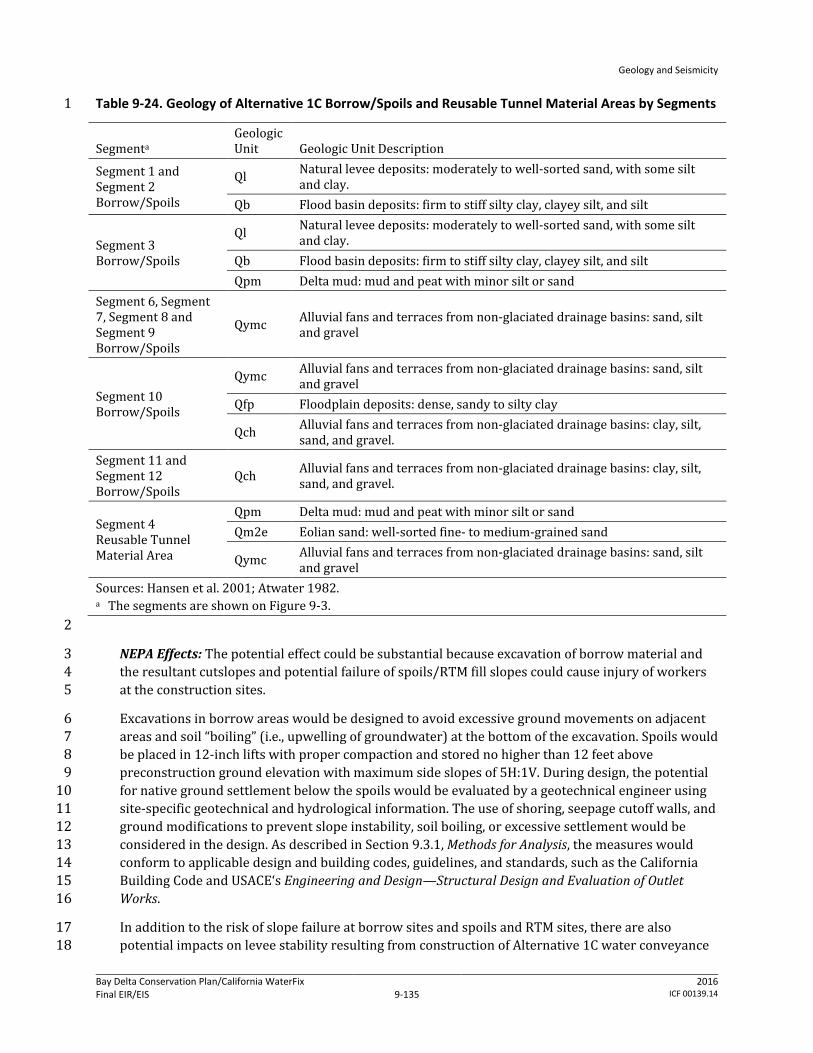
Geology and Seismicity
Bay Delta Conservation Plan/California WaterFix Final EIR/EIS
Administrative Final 9-135
2016 ICF 00139.14
Table 9-24. Geology of Alternative 1C Borrow/Spoils and Reusable Tunnel Material Areas by Segments 1
Segmenta Geologic Unit Geologic Unit Description
Segment 1 and Segment 2 Borrow/Spoils
Ql Natural levee deposits: moderately to well-sorted sand, with some silt and clay.
Qb Flood basin deposits: firm to stiff silty clay, clayey silt, and silt
Segment 3 Borrow/Spoils
Ql Natural levee deposits: moderately to well-sorted sand, with some silt and clay.
Qb Flood basin deposits: firm to stiff silty clay, clayey silt, and silt Qpm Delta mud: mud and peat with minor silt or sand
Segment 6, Segment 7, Segment 8 and Segment 9 Borrow/Spoils
Qymc Alluvial fans and terraces from non-glaciated drainage basins: sand, silt and gravel
Segment 10 Borrow/Spoils
Qymc Alluvial fans and terraces from non-glaciated drainage basins: sand, silt and gravel
Qfp Floodplain deposits: dense, sandy to silty clay
Qch Alluvial fans and terraces from non-glaciated drainage basins: clay, silt, sand, and gravel.
Segment 11 and Segment 12 Borrow/Spoils
Qch Alluvial fans and terraces from non-glaciated drainage basins: clay, silt, sand, and gravel.
Segment 4 Reusable Tunnel Material Area
Qpm Delta mud: mud and peat with minor silt or sand Qm2e Eolian sand: well-sorted fine- to medium-grained sand
Qymc Alluvial fans and terraces from non-glaciated drainage basins: sand, silt and gravel
Sources: Hansen et al. 2001; Atwater 1982. a The segments are shown on Figure 9-3. 2
NEPA Effects: The potential effect could be substantial because excavation of borrow material and 3 the resultant cutslopes and potential failure of spoils/RTM fill slopes could cause injury of workers 4 at the construction sites. 5
Excavations in borrow areas would be designed to avoid excessive ground movements on adjacent 6 areas and soil “boiling” (i.e., upwelling of groundwater) at the bottom of the excavation. Spoils would 7 be placed in 12-inch lifts with proper compaction and stored no higher than 12 feet above 8 preconstruction ground elevation with maximum side slopes of 5H:1V. During design, the potential 9 for native ground settlement below the spoils would be evaluated by a geotechnical engineer using 10 site-specific geotechnical and hydrological information. The use of shoring, seepage cutoff walls, and 11 ground modifications to prevent slope instability, soil boiling, or excessive settlement would be 12 considered in the design. As described in Section 9.3.1, Methods for Analysis, the measures would 13 conform to applicable design and building codes, guidelines, and standards, such as the California 14 Building Code and USACE‘s Engineering and Design—Structural Design and Evaluation of Outlet 15 Works. 16
In addition to the risk of slope failure at borrow sites and spoils and RTM sites, there are also 17 potential impacts on levee stability resulting from construction of Alternative 1C water conveyance 18
Geology and Seismicity
Bay Delta Conservation Plan/California WaterFix Final EIR/EIS
Administrative Final 9-136
2016 ICF 00139.14
facilities. The intakes would be sited along the existing Sacramento River levee system, requiring 1 reconstruction of levees to provide continued flood management. At each intake pumping plant site, 2 a new setback levee (ring levee) would be constructed. The space enclosed by the setback levee 3 would be filled up to the elevation of the top of the setback levee, creating a building pad for the 4 adjacent pumping plant. 5
As discussed in Chapter 3, Description of the Alternatives, the new levees would be designed to 6 provide an adequate Sacramento River channel cross section and to provide the same level of flood 7 protection as the existing levee and would be constructed to geometries that exceed PL 84-99 8 standards. Transition levees would be constructed to connect the existing levees to the new setback 9 levees. A typical new levee would have a broad-based, generally asymmetrical triangular cross 10 section. The levee height considered wind and wave erosion. As measured from the adjacent ground 11 surface on the landside vertically up to the elevation of the levee crest, would range from 12 approximately 20 to 45 feet to provide adequate freeboard above anticipated water surface 13 elevations. The width of the levee (toe of levee to toe of levee) would range from approximately 180 14 to 360 feet. The minimum crest width of the levee would be 20 feet; however, in some places it 15 would be larger to accommodate roadways and other features. Cut-off walls would be constructed to 16 avoid seepage, and the minimum slope of levee walls would be three units horizontal to one unit 17 vertical. All levee reconstruction would conform to applicable state and federal flood management 18 engineering and permitting requirements. 19
Depending on foundation material, foundation improvements would require excavation and 20 replacement of soil below the new levee footprint and potential ground improvement. The levees 21 would be armored with riprap—small to large angular boulders—on the waterside. Intakes would 22 be constructed using a sheetpile cofferdam in the river to create a dewatered construction area that 23 would encompass the intake site. The cofferdam would lie approximately 10–35 feet from the 24 footprint of the intake and would be built from upstream to downstream, with the downstream end 25 closed last. The distance between the face of the intake and the face of the cofferdam would be 26 dependent on the foundation design and overall dimensions. The length of each temporary 27 cofferdam would vary by intake location, but would range from 740 to 2,440 feet. Cofferdams would 28 be supported by steel sheet piles and/or king piles (heavy H-section steel piles). Installation of these 29 piles may require both impact and vibratory pile drivers. Some clearing and grubbing of levees 30 would be required prior to installation of the sheet pile cofferdam, depending on site conditions. 31 Additionally, if stone bank protection, riprap, or mature vegetation is present at intake construction 32 site, it would be removed prior to sheet pile installation. 33
As described in Section 9.3.1, Methods for Analysis, the measures would conform to applicable 34 construction, design and building codes, guidelines, and standards, such as the California Building 35 Code and USACE‘s Engineering and Design—Structural Design and Evaluation of Outlet Works. DWR 36 has made the environmental commitment (see Appendix 3B, Environmental Commitments, AMMs, 37 and CMs) that the geotechnical design recommendations are included in the construction and design 38 of project facilities and construction specifications to minimize the potential effects from failure of 39 excavations and settlement. DWR also has committed to ensure that the design specifications are 40 properly executed during construction. In particular, conformance with the following codes and 41 standards would reduce the potential risk for increased likelihood of loss of property or personal 42 injury from settlement/failure of cutslopes of borrow sites and failure of soil or RTM fill slopes 43 during construction. 44
Geology and Seismicity
Bay Delta Conservation Plan/California WaterFix Final EIR/EIS
Administrative Final 9-137
2016 ICF 00139.14
DWR Division of Engineering State Water Project—Seismic Loading Criteria Report, September 1 2012. 2
DWR Division of Flood Management FloodSAFE Urban Levee Design Criteria, May 2012. 3
8 CCR Sections 1509 and 3203. 4
Generally, the applicable codes require that facilities be built to certain factors of safety in order to 5 ensure that facilities perform as designed for the life of the structure despite various soil 6 parameters. The worker safety codes and standards specify protective measures that must be taken 7 at construction sites to minimize the risk of injury or death from structural or earth failure (e.g., 8 utilizing personal protective equipment, practicing crane and scaffold safety measures). The 9 relevant codes and standards represent performance standards that must be met by contractors and 10 these measures are subject to monitoring by state and local agencies. Cal-OSHA requirements for an 11 IIPP and the terms of the IIPP to protect worker safety are the principal measures that would be 12 enforced at construction sites. 13
Conformance to these and other applicable design specifications and standards would ensure that 14 construction of Alternative 1C would not create an increased likelihood of loss of property, personal 15 injury or death of individuals from slope failure at borrow sites and spoils and RTM storage sites. 16 The maintenance and reconstruction of levees would improve levee stability over existing 17 conditions due to improved side slopes, erosion control measures (geotextile fabrics, rock 18 revetments, or other material), seepage reduction measures, and overall mass. Therefore, there 19 would be no adverse effect. 20
CEQA Conclusion: Settlement/failure of cutslopes of borrow sites and failure of soil/RTM fill slopes 21 could result in loss of property or personal injury during construction. However, because DWR 22 would conform to Cal-OSHA and other state code requirements and conform to applicable 23 geotechnical design guidelines and standards, such as USACE design measures. Conformance with 24 these requirements and the application of accepted, proven construction engineering practices 25 would reduce any potential risk such that construction of Alternative 1C would not create an 26 increased likelihood of loss of property, personal injury or death of individuals from slope failure at 27 borrow sites and spoils and RTM storage sites. The maintenance and reconstruction of levees would 28 improve levee stability over existing conditions due to improved side slopes, erosion control 29 measures, seepage reduction measures, and overall mass. The impact would be less than significant. 30 No mitigation is required. 31
Impact GEO-5: Loss of Property, Personal Injury, or Death from Structural Failure Resulting 32 from Construction-Related Ground Motions during Construction of Water Conveyance 33 Features 34
Pile driving and other heavy equipment operations would cause vibrations that could initiate 35 liquefaction and associated ground movements in places where soil and groundwater conditions are 36 present to allow liquefaction to occur. The consequences of liquefaction could be manifested in 37 terms of compaction or settlement, loss of bearing capacity, lateral spreading (horizontal soil 38 movement), increased lateral soil pressure, and buoyancy within zones of liquefaction. These 39 consequences could cause loss of property or personal injury and could damage nearby structures 40 and levees. 41
Geology and Seismicity
Bay Delta Conservation Plan/California WaterFix Final EIR/EIS
Administrative Final 9-138
2016 ICF 00139.14
The lateral extent (or influenced distance) of damage potential caused by pile driving and heavy 1 equipment operations depends on many factors, including soil conditions, the piling hammer used, 2 frequency of piling, and the vibration tolerance of structures and levees. 3
Pile driving would be conducted at the intakes, where, based on boring logs, soil materials subject to 4 liquefaction (e.g., saturated, poorly graded sand) are present. In addition to pile driving activities, 5 construction of the water conveyance facilities would require an increased volume of truck and 6 heavy equipment traffic that may occur at some of these locations. Although the trucks and heavy 7 equipment could generate vibrations in the levees, the severity of the vibrations is not expected to 8 be capable of initiating liquefaction. Construction related to conveyance facilities would also require 9 regular access to construction sites, extending the length of the project. Some of the existing public 10 roads would be used as haul routes for the construction of conveyance facilities. Use of the state 11 highway system as haul routes would be maximized where feasible because these roadways are 12 rated for truck traffic and would generally provide the most direct and easily maneuverable routes 13 for large loads. As part of future engineering phases, haul routes needed for the construction of the 14 approved project would be refined. Construction traffic may need to access levee roads at various 15 points along SR 160 and other state routes as shown in Figure 9-7, as well as at locations shown 16 along the West Alignment in Figure 9-8a. Because of the volume of truck traffic that may occur at 17 some of these locations, there is the potential for some effect on levee integrity at various locations 18 depending on the site specific levee conditions along access routes. 19
During project design, site-specific geotechnical and groundwater investigations would be 20 conducted to build upon existing data (e.g., California Department of Water Resources 2009b, 21 2010d, 2010i) to identify and characterize the vertical (depth) and horizontal (spatial) variability in 22 soil bearing capacity and extent of liquefiable soil. Engineering soil parameters that could be used to 23 assess the liquefaction potential, such as SPT blow counts, CPT penetration tip pressure/resistance, 24 and gradation of soil, would also be obtained. SPT blow counts and CPT tip pressure are used to 25 estimate soil resistance to cyclic loadings by using empirical relationships that were developed 26 based on occurrences of liquefaction (or lack of them) during past earthquakes (i.e., the earthquake 27 that is expected to produce the strongest level of ground shaking at a site to which it is appropriate 28 to design a structure to withstand). The resistance then can be compared to cyclic shear stress 29 induced by the design earthquakes. If soil resistance is less than induced stress, the potential of 30 having liquefaction during the design earthquakes is high. It is also known that soil with high “fines” 31 (i.e., silt- and clay-sized particles) content are less susceptible to liquefaction. 32
NEPA Effects: The potential effect could be substantial because construction-related ground motions 33 could initiate liquefaction, which could cause failure of structures during construction. Some of the 34 potential levee effects that could occur during the construction in the absence of corrective 35 measures may include rutting, settlement, and slope movement. 36
During design, the facility-specific potential for liquefaction would be investigated by a geotechnical 37 engineer. The potential effects of construction vibrations on nearby structures, levees, and utilities 38 would be evaluated using specific piling information (such as pile type, length, spacing, and pile-39 driving hammer to be used). In areas determined to have a potential for liquefaction, the engineer 40 would develop design measures and construction methods to ensure that pile driving and heavy 41 equipment operations do not damage facilities under construction and surrounding structures and 42 do not threaten the safety of workers at the site. As shown in Figure 9-6, a majority of Alternative 1C 43 crosses through an area classified as medium to low liquefaction hazard. Alternative 1C also runs 44 through Brannan Island and Twitchell Island, which have medium to medium-high levee 45

Geology and Seismicity
Bay Delta Conservation Plan/California WaterFix Final EIR/EIS
Administrative Final 9-139
2016 ICF 00139.14
liquefaction damage potential. A barge unloading facility is located at the northern end of Brannan 1 Island in this medium to medium-high levee liquefaction damage potential area. Design strategies 2 may include predrilling or jetting, using open-ended pipe piles to reduce the energy needed for pile 3 penetration, using CIDH piles/piers that do not require driving, using pile jacking to press piles into 4 the ground by means of a hydraulic system, or driving piles during the drier summer months. Field 5 data collected during design also would be evaluated to determine the need for and extent of 6 strengthening levees, embankments, and structures to reduce the effect of vibrations. These 7 construction methods would conform to current seismic design codes and requirements, as 8 described in Chapter 3, Description of the Alternatives. Such design standards include USACE‘s 9 Engineering and Design—Stability Analysis of Concrete Structures and Soil Liquefaction during 10 Earthquakes, by the Earthquake Engineering Research Institute. 11
As with the effects related to design of conveyance facilities, potential construction traffic effects on 12 levees would be assessed prior to project construction to determine specific geotechnical issues 13 related to construction traffic loading. Based on the initial assessment from field reconnaissance, 14 geotechnical exploration and analyses would be performed for levee sections that need further 15 evaluations. Should the geotechnical evaluations indicate that certain segments of existing levee 16 roads need improvements to carry the expected construction truck traffic loads, DWR is committed 17 to carry out the necessary improvements to the affected levee sections or to find an alternative route 18 that would avoid the potential deficient levee sections (Mitigation Measures TRANS-2a through 2c). 19 As discussed in Chapter 19, Transportation, Mitigation Measure TRANS-2c, all affected roadways 20 would be returned to preconstruction condition or better following construction. Implementation of 21 this measure would ensure that construction activities would not worsen pavement and levee 22 conditions, relative to existing conditions. Prior to construction, DWR would make a good faith effort 23 to enter into mitigation agreements with or to obtain encroachment permits from affected agencies 24 to verify what the location, extent, timing, and fair share cost to be paid by the DWR for any 25 necessary pre- and post-construction physical improvements. Levee roads that are identified as 26 potential haul routes and expected to carry significant construction truck traffic would be monitored 27 to ensure that truck traffic is not adversely affecting the levee and to identify the need for corrective 28 action. 29
DWR has made the environmental commitment (see Appendix 3B, Environmental Commitments, 30 AMMs, and CMs) recommended by the geotechnical engineer are included in the design of project 31 facilities and construction specifications to minimize the potential for construction-induced 32 liquefaction. DWR also has committed to ensure that these methods are followed during 33 construction. 34
In particular, conformance with the following codes and standards would reduce the potential risk 35 for increased likelihood of loss of property or personal injury from structural failure resulting from 36 construction-related ground motions. 37
USACE Engineering and Design—Design of Pile Foundations, EM 1110-2-2906, 1991. 38
USACE Engineering and Design—Earthquake Design and Evaluation for Civil Works Projects, 39 ER 1110-2-1806, 1995. 40
8 CCR Sections 1509 and 3203. 41
Generally, the applicable codes require that facilities be built so that if soil in the foundation or 42 surrounding area are subject to liquefaction, the removal or densifaction of the liquefiable material 43
Geology and Seismicity
Bay Delta Conservation Plan/California WaterFix Final EIR/EIS
Administrative Final 9-140
2016 ICF 00139.14
should be considered, along with alternative foundation designs. Additionally, any modification to a 1 federal levee system would require USACE approval under 33 USC 408 (a 408 Permit). 2
The worker safety codes and standards specify protective measures that must be taken at 3 construction sites to minimize the risk of injury or death from structural or earth failure (e.g., 4 utilizing personal protective equipment, practicing crane and scaffold safety measures). The 5 relevant codes and standards represent performance standards that must be met by contractors and 6 these measures are subject to monitoring by state and local agencies. Cal-OSHA requirements for an 7 IIPP and the terms of the IIPP to protect worker safety are the principal measures that would be 8 enforced at construction sites. 9
Conformance to construction methods recommendations and other applicable specifications, as well 10 as implementation of Mitigation Measures TRANS-2a through 2c, would ensure that construction of 11 Alternative 1C would not create an increased likelihood of loss of property, personal injury or death 12 of individuals due to construction- and traffic-related ground motions and resulting potential 13 liquefaction in the work area. Therefore, the effect would not be adverse. 14
CEQA Conclusion: Construction-related ground motions and traffic effects could initiate 15 liquefaction, which could cause failure of structures during construction, which could result in injury 16 of workers at the construction sites. The impact could be significant. However, DWR has committed 17 to conform to Cal-OSHA and other state code requirements and conform to applicable design 18 guidelines and standards, such as USACE design measures. Conformance with these requirements 19 and the application of accepted, proven construction engineering practices, in addition to 20 implementation of Mitigation Measures TRANS-2a and TRANS-2b, as well as the maintenance and 21 reconstruction of levees through Mitigation Measure TRANS-2c, would reduce any potential risk 22 such that construction of Alternative 1C would not create an increased likelihood of loss of property, 23 personal injury or death of individuals from construction-related ground motion and resulting 24 potential liquefaction in the work area and the hazard would be controlled to a level that would 25 protect worker safety (see Appendix 3B, Environmental Commitments, AMMs, and CMs). The impact 26 would be less than significant. 27
Mitigation Measure TRANS-2a: Prohibit Construction Activity on Physically Deficient 28 Roadway Segments 29
Please refer to Mitigation Measure TRANS-2a in Alternative 1A, Impact TRANS-2, in Chapter 19, 30 Transportation. 31
Mitigation Measure TRANS-2b: Limit Construction Activity on Physically Deficient 32 Roadway Segments 33
Please refer to Mitigation Measure TRANS-2b in Alternative 1A, Impact TRANS-2, in Chapter 19, 34 Transportation. 35
Mitigation Measure TRANS-2c: Improve Physical Condition of Affected Roadway Segments 36 as Stipulated in Mitigation Agreements or Encroachment Permits 37
Please refer to Mitigation Measure TRANS-2c in Alternative 1A, Impact TRANS-2, in Chapter 19, 38 Transportation. 39

Geology and Seismicity
Bay Delta Conservation Plan/California WaterFix Final EIR/EIS
Administrative Final 9-141
2016 ICF 00139.14
Impact GEO-6: Loss of Property, Personal Injury, or Death from Structural Failure Resulting 1 from Rupture of a Known Earthquake Fault during Operation of Water Conveyance Features 2
According to the available AP Earthquake Fault Zone Maps, none of the Alternative 1C facilities 3 would cross or be within any known active fault zones. However, numerous AP fault zones have 4 been mapped west of the conveyance alignment (Figure 9-5). The closest AP fault zone would be the 5 Greenville fault, located approximately 8.1 miles west of the Alternative 1C conveyance facilities. 6 The Midway fault is also mapped approximately 3.4 miles west of the Alternative 1C conveyance 7 facilities, near the cities of Tracy and Livermore. Because none of the Alternative 1C constructed 8 facilities would be within any of the fault zones (which include the area approximately 200 to 500 9 feet on each side of the mapped surface trace to account for potential branches of active faults) the 10 potential that the facilities would be directly subject to fault offsets is negligible. 11
In the Delta, active or potentially active blind thrust faults were identified in the seismic study. 12 Segment 4 of the Alternative 1C conveyance alignment would cross the Southern Midland fault and 13 continue through the Montezuma Hills fault zone. Segment 5 and part of Segment 6 would also cross 14 the Montezuma Hills fault zone. The western part of the proposed Byron Tract Forebay adjacent to 15 the Clifton Court Forebay is underlain by the West Tracy fault and the southernmost segment of the 16 Southern Midland fault. Although these blind thrusts are not expected to rupture to the ground 17 surface under the forebays during earthquake events, they may produce ground or near-ground 18 shear zones, bulging, or both (California Department of Water Resources 2007a). Assuming that the 19 West Tracy fault is potentially active, it could cause surface deformation in the western part of the 20 Clifton Court Forebay. Because the western part of the Byron Tract Forebay is also underlain by the 21 hanging wall of the fault, this part of the forebay may also experience uplift and resultant surface 22 deformation (Fugro Consultants 2011). In the seismic study, the South Midland, Montezuma Hills, 23 and West Tracy blind thrusts were assigned 80%, 50%, and 90% probabilities of being active, 24 respectively (California Department of Water Resources 2007a). 25
The depth to the Montezuma Hills faults is unknown. The seismic study (California Department of 26 Water Resources 2007a) indicates that the West Tracy fault dies out as a discernible feature within 27 approximately 3,000 to 6,000 feet bgs (in the upper 1 to 2 second depth two-way time, estimated to 28 be approximately 3,000 to 6,000 feet using the general velocity function as published in the 29 Association of Petroleum Geologists Pacific Section newsletter [Tolmachoff 1993]). This same study 30 indicates that the tip of the Southern Midway fault is said to extend above the base of the Tertiary 31 Markley Formation to depths of about 1.5 km or 4,900 feet, and possibly shallower. The minimum 32 fault depth has not been determined. 33
It appears that the potential of having any shear zones, bulging, or both at the depths of the canal 34 and the proposed forebay at Clifton Court is low because the depth to the blind thrust faults is 35 generally deep. 36
NEPA Effects: The effect would not be adverse, because no active faults capable of surface rupture 37 extend into the Alternative 1C alignment. Additionally, although the West Tracy blind thrust occurs 38 beneath the Alternative 1C alignment, based on available information, it do not present a hazard of 39 surface rupture. 40
However, because there is limited information regarding the depths of these faults, seismic surveys 41 would be performed on the South Midland, Montezuma Hills, and West Tracy blind thrusts during 42 the design phase to determine the depths to the top of the faults. More broadly, design-level 43 geotechnical studies would be prepared by a geotechnical engineer licensed in the state of California 44
Geology and Seismicity
Bay Delta Conservation Plan/California WaterFix Final EIR/EIS
Administrative Final 9-142
2016 ICF 00139.14
during project design. The studies would further assess site-specific conditions at and near all the 1 project facility locations, including seismic activity, soil liquefaction, and other potential geologic 2 and soil-related hazards. This information would be used to verify assumptions and conclusions 3 included in the EIR/EIS. The geotechnical engineer’s recommended measures to address adverse 4 conditions would conform to applicable design codes, guidelines, and standards. Potential design 5 strategies or conditions could include avoidance (deliberately positioning structures and lifelines to 6 avoid crossing identified shear rupture zones), geotechnical engineering (using the inherent 7 capability of unconsolidated geomaterials to “locally absorb” and distribute distinct bedrock fault 8 movements) and structural engineering (engineering the facility to undergo some limited amount of 9 ground deformation without collapse or significant damage). 10
As described in Section 9.3.1, Methods for Analysis, such design codes, guidelines, and standards are 11 environmental commitments by DWR (see also Appendix 3B, Environmental Commitments, AMMs, 12 and CMs). For construction of the water conveyance facilities, the codes and standards would 13 include the California Building Code and resource agency and professional engineering 14 specifications, such as the Division of Safety of Dams’ Guidelines for Use of the Consequence-Hazard 15 Matrix and Selection of Ground Motion Parameters, DWR’s Division of Flood Management FloodSAFE 16 Urban Levee Design Criteria, and USACE‘s Engineering and Design—Earthquake Design and 17 Evaluation for Civil Works Projects. These codes and standards include minimum performance 18 standards for structural design, given site-specific subsurface conditions. 19
DWR would ensure that the geotechnical design recommendations are included in the design of 20 project facilities and construction specifications to minimize the potential effects from seismic 21 events and the presence of adverse soil conditions. DWR would also ensure that the design 22 specifications are properly executed during construction. 23
In particular, conformance with the following codes and standards would reduce the potential risk 24 for increased likelihood of loss of property or personal injury from structural failure resulting from 25 surface rupture resulting from a seismic event during operation. 26
DWR Division of Engineering State Water Project—Seismic Loading Criteria Report, September 27 2012. 28
USACE Engineering and Design—Time-History Dynamic Analysis of Concrete Hydraulic Structures, 29 EM 1110-2-6051, 2003. 30
USACE Engineering and Design—Response Spectra and Seismic Analysis for Concrete Hydraulic 31 Structures, EM 1110-2-6050, 1999. 32
American Society of Civil Engineers Minimum Design Loads for Buildings and Other Structures, 33 ASCE/SEI 7-10, 2010. 34
8 CCR 3203. 35
Generally, the applicable codes require that facilities be built so that they incur minimal damage in 36 the event of a foreseeable seismic event and that they remain functional following such an event and 37 that the facility is able to perform without catastrophic failure in the event of a maximum design 38 earthquake (the greatest earthquake reasonably expected to be generated by a specific source on 39 the basis of seismological and geological evidence). 40
The worker safety codes and standards specify protective measures that must be taken at 41 workplaces to minimize the risk of injury or death from structural or earth failure (e.g., utilizing 42

Geology and Seismicity
Bay Delta Conservation Plan/California WaterFix Final EIR/EIS
Administrative Final 9-143
2016 ICF 00139.14
personal protective equipment). The relevant codes and standards represent performance 1 standards that must be met by employers and these measures are subject to monitoring by state and 2 local agencies. Cal-OSHA requirements for an IIPP and the terms of the IIPP to protect worker safety 3 are the principal measures that would be enforced at workplaces. 4
Conformance to these and other applicable design specifications and standards would ensure that 5 operation of Alternative 1C would not create an increased likelihood of loss of property, injury or 6 death of individuals in the event of ground movement in the vicinity of the South Midland, 7 Montezuma Hills, and West Tracy blind thrusts and would not jeopardize the integrity of the surface 8 and subsurface facilities along the Alternative 1C conveyance alignment or the proposed forebay 9 and associated facilities adjacent to the Clifton Court Forebay. Therefore, there would be no adverse 10 effect. 11
CEQA Conclusion: There are no active faults capable of surface rupture that extend into the 12 Alternative 1C alignment. Although the Montezuma Hills, West Tracy and South Midland blind 13 thrusts occur beneath the Alternative 1C alignment, based on available information, they do not 14 present a hazard of surface rupture. Conformance to applicable design specifications and standards 15 would ensure that operation of Alternative 1C would not create an increased likelihood of loss of 16 property, personal injury or death of individuals in the event of ground movement in these areas 17 and would not jeopardize the integrity of the surface and subsurface facilities along the Alternative 18 1C conveyance alignment or the proposed forebay and associated facilities adjacent to the Clifton 19 Court Forebay. There would be no impact. No mitigation is required. 20
Impact GEO-7: Loss of Property, Personal Injury, or Death from Structural Failure Resulting 21 from Strong Seismic Shaking during Operation of Water Conveyance Features 22
Earthquake events may occur on the local and regional seismic sources during operation of the 23 Alternative 1C water conveyance facilities. The ground shaking could damage the canals, pipelines, 24 tunnels, culvert siphons, intake facilities, pumping plants, and other facilities, disrupting the water 25 supply through the conveyance system. In an extreme event of strong seismic shaking, uncontrolled 26 release of water from the damaged canal, pipelines, tunnel, culvert siphons, intake facilities, 27 pumping plants, and other facilities could cause flooding, disruption of water supplies to the south, 28 and inundation of structures. These effects are discussed more fully in Appendix 3E, Potential 29 Seismicity and Climate Change Risks to SWP/CVP Water Supplies. 30
The potential of earthquake ground shaking in the early long-term (2025) was estimated using the 31 results of the seismic study (California Department of Water Resources 2007a). Table 9-25 lists the 32 expected PGA and 1.0-Sa values in 2025 at selected facility locations for the early long-term. 33 Earthquake ground shaking for the OBE (144-year return period) and MDE (975-year return period) 34 was estimated for the stiff soil site, as predicted in the seismic study (California Department of 35 Water Resources 2007a), and for the anticipated soil conditions at the facility locations. No seismic 36 study results exist for 2025, so the ground shaking estimated for 2050 was used for the early long-37 term (2025). 38
Table 9-25 shows that the proposed facilities would be subject to moderate-to-high earthquake 39 ground shaking in the early long-term (2025). All facilities would be designed and constructed in 40 accordance with the requirements of the design measures described earlier in this chapter. 41 Site-specific geotechnical information would be used to further assess the effect of local soil on the 42 OBE and MDE ground shaking and to develop design criteria to minimize the potential of damage. 43

Geology and Seismicity
Bay Delta Conservation Plan/California WaterFix Final EIR/EIS
Administrative Final 9-144
2016 ICF 00139.14
NEPA Effects: This potential effect could be substantial because strong ground shaking could 1 damage pipelines, tunnel, culvert siphons, intake facilities, pumping plants, and other facilities. The 2 damage could disrupt the water supply through the conveyance system. In an extreme event, an 3 uncontrolled release of water from the conveyance system could cause flooding and inundation of 4 structures. Please refer to Chapter 6, Surface Water and Appendix 3E, Potential Seismicity and 5 Climate Change Risks to SWP/CVP Water Supplies, for a detailed discussion of potential flood effects. 6
Table 9-25. Expected Earthquake Ground Motions at Locations of Selected Major Facilities in the Early 7 Long-Term (2025)—Alternative 1C 8
Major Facilities
144-Year Return Period Ground Motions (OBE) PGA (g)
1.0-Sec Sa (g)
Stiff Soila Local Soilb Stiff Soila Local Soilb Intake and Fish Screen Areac 0.14 0.15 0.19 0.30 Tunnel Location between Bradford Island and Webb Tractd
0.30 0.33 0.31 0.50
Clifton Court Forebay/Byron Tract Forebay 0.28 0.31 0.30 0.48
Major Facilities
975-Year Return Period Ground Motions (MDE) PGA (g)
1.0-Sec Sa (g)
Stiff Soila Local Soile Stiff Soila Local Soile Intake and Fish Screen Areac 0.24 0.24 0.33 0.53 Tunnel Location between Bradford Island and Webb Tractd
0.50 0.50 0.60 0.96
Clifton Court Forebay/Byron Tract Forebay 0.50 0.50 0.61 0.98 g = gravity. MDE = maximum design earthquake. OBE = operating basis earthquake. PGA = Peak Ground Acceleration. Sa = second spectral acceleration. a Stiff soil site, with a Vs100ft value of 1,000 ft/s. b Site-adjusted factors of 1.1 and 1.60 were applied to PGA and 1.0-sec Sa values, respectively. c The results of California Department of Water Resources 2007a for the Sacramento site were used. d The results of California Department of Water Resources 2007a for the Sherman Island were used. e Site-adjusted factors of 1.0 and 1.60 were applied to PGA and 1.0-sec Sa values, respectively. 9
Design-level geotechnical studies would be conducted by a licensed civil engineer who practices in 10 geotechnical engineering. The studies would assess site-specific conditions at and near all the 11 project facility locations and provide the basis for designing the conveyance features to withstand 12 the peak ground acceleration caused by fault movement in the region. The California-registered civil 13 engineer or California-certified engineering geologist’s recommended measures to address this 14 hazard would conform to applicable design codes, guidelines, and standards. As described in in the 15 methodology section in this chapter and in Appendix 3B, Environmental Commitments, AMMs, and 16 CMs, such design codes, guidelines, and standards include the California Building Code and resource 17 agency and professional engineering specifications, such as the Division of Safety of Dams’ Guidelines 18 for Use of the Consequence-Hazard Matrix and Selection of Ground Motion Parameters, DWR‘s 19 Division of Flood Management FloodSAFE Urban Levee Design Criteria, and USACE‘s Engineering and 20 Design—Earthquake Design and Evaluation for Civil Works Projects. Conformance with these codes 21 and standards are an environmental commitment by DWR to ensure that ground shaking risks are 22 minimized as the water conveyance features are operated. 23
Geology and Seismicity
Bay Delta Conservation Plan/California WaterFix Final EIR/EIS
Administrative Final 9-145
2016 ICF 00139.14
DWR would ensure that the geotechnical design recommendations are included in the design of 1 project facilities and construction specifications to minimize the potential effects from seismic 2 events and the presence of adverse soil conditions. DWR would also ensure that the design 3 specifications are properly executed during construction. See Appendix 3B, Environmental 4 Commitments, AMMs, and CMs. 5
In particular, conformance with the following codes and standards would reduce the potential risk 6 for increased likelihood of loss of property or personal injury from structural failure resulting from 7 strong seismic shaking of water conveyance features during operations. 8
DWR Division of Engineering State Water Project—Seismic Loading Criteria Report, September 9 2012. 10
USACE Engineering and Design—Time-History Dynamic Analysis of Concrete Hydraulic Structures, 11 EM 1110-2-6051, 2003. 12
USACE Engineering and Design—Response Spectra and Seismic Analysis for Concrete Hydraulic 13 Structures, EM 1110-2-6050, 1999. 14
American Society of Civil Engineers Minimum Design Loads for Buildings and Other Structures, 15 ASCE/SEI 7-10, 2010. 16
8 CCR 3203. 17
Generally, the applicable codes require that facilities be built so that they incur minimal damage in 18 the event of a foreseeable seismic event and that they remain functional following such an event and 19 that the facility is able to perform without catastrophic failure in the event of a maximum design 20 earthquake (the greatest earthquake reasonably expected to be generated by a specific source on 21 the basis of seismological and geological evidence). 22
Conformance with these standards and codes are an environmental commitment of the project (see 23 Appendix 3B, Environmental Commitments, AMMs, and CMs). The worker safety codes and standards 24 specify protective measures that must be taken at workplaces to minimize the risk of injury or death 25 from structural or earth failure (e.g., utilizing personal protective equipment). The relevant codes 26 and standards represent performance standards that must be met by employers and these measures 27 are subject to monitoring by state and local agencies. Cal-OSHA requirements for an IIPP and the 28 terms of the IIPP to protect worker safety are the principal measures that would be enforced at 29 workplaces during operations. 30
Conformance to these and other applicable design specifications and standards would ensure that 31 operation of Alternative 1C would not create an increased likelihood of loss of property, personal 32 injury or death of individuals from structural shaking of surface and subsurface facilities along the 33 Alternative 1C conveyance alignment in the event of strong seismic shaking. Therefore, there would 34 be no adverse effect. 35
CEQA Conclusion: Seismically induced strong ground shaking could damage the canals, pipelines, 36 culvert siphons, intake facilities, pumping plants, and other facilities. The damage could disrupt the 37 water supply through the conveyance system. In an extreme event, an uncontrolled release of water 38 from the damaged conveyance system could cause flooding and inundation of structures. (Please 39 refer to Chapter 6, Surface Water, for a detailed discussion of potential flood impacts.) However, 40 through the final design process, measures to address this hazard would be required to conform to 41 applicable design codes, guidelines, and standards. As described in Section 9.3.1, Methods for 42
Geology and Seismicity
Bay Delta Conservation Plan/California WaterFix Final EIR/EIS
Administrative Final 9-146
2016 ICF 00139.14
Analysis, and in Appendix 3B, Environmental Commitments, AMMs, and CMs, such design codes, 1 guidelines, and standards include the California Building Code and resource agency and professional 2 engineering specifications, such as the Division of Safety of Dams Guidelines for Use of the 3 Consequence-Hazard Matrix and Selection of Ground Motion Parameters, DWR‘s Division of Flood 4 Management FloodSAFE Urban Levee Design Criteria, and USACE‘s Engineering and Design—5 Earthquake Design and Evaluation for Civil Works Projects. Conformance with these codes and 6 standards is an environmental commitment by DWR to ensure that ground shaking risks are 7 minimized as the Alternative 1C water conveyance features are operated and there would be no 8 increased likelihood of loss of property, personal injury or death of individuals. The hazard would be 9 controlled to a safe level. The impact would be less than significant. No mitigation is required. 10
Impact GEO-8: Loss of Property, Personal Injury, or Death from Structural Failure Resulting 11 from Seismic-Related Ground Failure (Including Liquefaction) during Operation of Water 12 Conveyance Features 13
Earthquake-induced ground shaking could cause liquefaction, resulting soil slumping or lateral 14 spreading and subsequent damage to or breaching of water conveyance structures and facilities. The 15 consequences of liquefaction are manifested in terms of compaction or settlement, loss of bearing 16 capacity, lateral spreading (soil movement), increased lateral soil pressure, and buoyancy within 17 zones of liquefaction. Failure of the canal, tunnel, culvert siphons, pipelines, levees, bridges, and 18 other structures and facilities could result in loss and injury and disrupt SWP and CVP water supply 19 deliveries. The potential for impacts from flooding as a result of levee or dam failure is also 20 discussed in Chapter 6, Surface Water. 21
The native soils underlying the southern part of the Alternative 1C alignment consist primarily of 22 alluvial fan and terrace deposits, including clay, silt, sand and gravels of variable density. The 23 northern part of the alignment is more variable in composition, consisting of natural levee, basin, 24 and Delta mud deposits. The central portion (Segment 4), through which the tunnel would be 25 constructed, consists of natural levee, eolian sand, Delta mud, alluvial fans, and dredge spoils. The 26 more recently deposited, sandy materials would be more prone to liquefaction. Figure 9-6 shows 27 that the Alternative 1C alignment has no substantial liquefaction damage potential in its northern 28 part and low to medium-high damage potential in its central and southern parts. 29
NEPA Effects: The potential effect could be substantial because seismically induced ground shaking 30 could cause liquefaction, which could damage pipelines, tunnel, culvert siphons, intake facilities, 31 pumping plants, and other facilities. The damage could disrupt the water supply through the 32 conveyance system. In an extreme event, an uncontrolled release of water from the damaged 33 conveyance system could cause flooding and inundation of structures. Please refer to Chapter 6, 34 Surface Water and Appendix 3E, Potential Seismicity and Climate Change Risks to SWP/CVP Water 35 Supplies, for a detailed discussion of potential flood effects. 36
In the process of preparing final facility designs, site-specific geotechnical and groundwater 37 investigations would be conducted to identify and characterize the vertical (depth) and horizontal 38 (spatial) extents of liquefiable soil. Engineering soil parameters that could be used to further assess 39 the liquefaction potential, such as SPT blow counts, CPT penetration tip pressure/resistance, and 40 gradation of soil, would also be obtained. SPT blow counts and CPT tip pressure are used to estimate 41 soil resistance to cyclic loadings by using empirical relationships that were developed based on 42 occurrences of liquefaction (or lack of them) during past earthquakes. The resistance then can be 43 compared to cyclic shear stress induced by the design earthquakes. If soil resistance is less than 44

Geology and Seismicity
Bay Delta Conservation Plan/California WaterFix Final EIR/EIS
Administrative Final 9-147
2016 ICF 00139.14
induced stress, the potential of having liquefaction during the design earthquakes is high. It is also 1 known that soil with high “fines” (i.e., silt- and clay-sized particles) content are less susceptible to 2 liquefaction. 3
During final design, site-specific potential for liquefaction would be investigated by a geotechnical 4 engineer. In areas determined to have a potential for liquefaction, a California-registered civil 5 engineer or California-certified engineering geologist would develop design measures and 6 construction methods to meet design criteria established by building codes and construction 7 standards to ensure that design earthquake does not cause damage to or failure of the facility. Such 8 measures and methods include removing and replacing potentially liquefiable soil, strengthening 9 foundations (for example, and using post-tensioned slab, reinforced mats, and piles) to resist 10 excessive total and differential settlements, using in situ ground improvement techniques (such as 11 deep dynamic compaction, vibro-compaction, vibro-replacement, compaction grouting, and other 12 similar methods). The results of the site-specific evaluation and California-registered civil engineer 13 or California-certified engineering geologist’s recommendations would be documented in a detailed 14 geotechnical report prepared in accordance with state guidelines, in particular Guidelines for 15 Evaluating and Mitigating Seismic Hazards in California (California Geological Survey 2008). As 16 described in Section 9.3.1, Methods for Analysis, and in Appendix 3B, Environmental Commitments, 17 AMMs, and CMs, such design codes, guidelines, and standards include USACE‘s Engineering and 18 Design—Earthquake Design and Evaluation for Civil Works Projects and Liquefaction during 19 Earthquakes, by the Earthquake Engineering Research Institute. Conformance with these design 20 requirements is an environmental commitment by DWR to ensure that liquefaction risks are 21 minimized as the water conveyance features are operated. 22
DWR would ensure that the geotechnical design recommendations are included in the design of 23 project facilities and construction specifications to minimize the potential effects from liquefaction 24 and associated hazard. DWR would also ensure that the design specifications are properly executed 25 during construction. 26
In particular, conformance with the following codes and standards would reduce the potential risk 27 for increased likelihood of loss of property or personal injury from structural failure resulting from 28 strong seismic shaking of water conveyance features during operations. 29
DWR Division of Engineering State Water Project—Seismic Loading Criteria Report, September 30 2012. 31
USACE Engineering and Design—Time-History Dynamic Analysis of Concrete Hydraulic Structures, 32 EM 1110-2-6051, 2003. 33
USACE Engineering and Design—Response Spectra and Seismic Analysis for Concrete Hydraulic 34 Structures, EM 1110-2-6050, 1999. 35
American Society of Civil Engineers Minimum Design Loads for Buildings and Other Structures, 36 ASCE/SEI 7-10, 2010. 37
USACE Engineering and Design—Design of Pile Foundations, EM 1110-2-2906, 1991 38
8 CCR 3203. 39
Generally, the applicable codes require that facilities be built so that if soil in the foundation or 40 surrounding area are subject to liquefaction, the removal or densifaction of the liquefiable material 41
Geology and Seismicity
Bay Delta Conservation Plan/California WaterFix Final EIR/EIS
Administrative Final 9-148
2016 ICF 00139.14
should be considered, along with alternative foundation designs. Additionally, any modification to a 1 federal levee system would require USACE approval under 33 USC 408 (a 408 Permit). 2
The worker safety codes and standards specify protective measures that must be taken at 3 workplacesto minimize the risk of injury or death from structural or earth failure (e.g., utilizing 4 personal protective equipment). The relevant codes and standards represent performance 5 standards that must be met by employers and these measures are subject to monitoring by state and 6 local agencies. Cal-OSHA requirements for an IIPP and the terms of the IIPP to protect worker safety 7 are the principal measures that would be enforced at workplacesduring operations. 8
Conformance to these and other applicable design specifications and standards would ensure that 9 the hazard of liquefaction and associated ground movements would not create an increased 10 likelihood of loss of property, personal injury or death of individuals from structural failure of 11 surface and subsurface facilities resulting from seismic-related ground failure along the Alternative 12 1C conveyance alignment during operation of the water conveyance features. Therefore, the effect 13 would not be adverse. 14
CEQA Conclusion: Seismically induced ground shaking could cause liquefaction, which could result 15 in loss of property or personal injury. Liquefaction could damage pipelines, tunnel, culvert siphons, 16 intake facilities, pumping plants, and other facilities, and thereby disrupt the water supply through 17 the conveyance system. In an extreme event, flooding and inundation of structures could result from 18 an uncontrolled release of water from the damaged conveyance system. (Please refer to Chapter 6, 19 Surface Water, for a detailed discussion of potential flood impacts.) However, through the final 20 design process, measures to address the liquefaction hazard would be required to conform to 21 applicable design codes, guidelines, and standards. As described in Section 9.3.1, Methods for 22 Analysis, and in Appendix 3B, Environmental Commitments, AMMs, and CMs, such design codes, 23 guidelines, and standards include USACE‘s Engineering and Design—Stability Analysis of Concrete 24 Structures and Soil Liquefaction during Earthquakes, by the Earthquake Engineering Research 25 Institute. Conformance with these design standards is an environmental commitment by DWR to 26 ensure that liquefaction risks are minimized as the Alternative 1C water conveyance features are 27 operated and there would be no increased likelihood of loss of property, personal injury or death of 28 individuals. The hazard would be controlled to a safe level. The impact would be less than 29 significant. No mitigation is required. 30
Impact GEO-9: Loss of Property, Personal Injury, or Death from Landslides and Other Slope 31 Instability during Operation of Water Conveyance Features 32
Alternative 1C would involve excavation that creates new cut-and-fill slopes and construction of 33 new embankments and levees. As a result of ground shaking and high soil-water content during 34 heavy rainfall, existing and new slopes that are not properly engineered and natural stream banks 35 could fail and cause damage to facilities. Levees can fail for several reasons: 1) high velocities of 36 water flow can result in high rates of erosion and erode and overtop a levee; 2) the higher velocities 37 of water flow can also lead to higher rates of erosion along the inner parts of levees and lead to 38 undercutting and clumping of the levee into the river. Heavy rainfall or seepage into the levee from 39 the river can increase fluid pressure in the levee and lead to slumping on the outer parts of the levee. 40 If the slumps grow to the top of the levee, large sections of the levee may slump onto the floodplain 41 and lower the elevation of the top of the levee, leading to overtopping; 3) increasing levels of water 42 in the river will cause the water table in the levee to rise which will increase fluid pressure and may 43
Geology and Seismicity
Bay Delta Conservation Plan/California WaterFix Final EIR/EIS
Administrative Final 9-149
2016 ICF 00139.14
result in seepage and eventually lead to internal erosion called piping. Piping will erode the material 1 under the levee, undermining it and causing its collapse and failure. 2
With the exception of levee slopes and natural stream banks, the topography along the Alternative 3 1C conveyance alignment is nearly level to very gently sloping. The areas that may be susceptible to 4 slope failure are along existing levee slopes and at intake, pumping plant, forebay, and certain access 5 road locations. Outside these areas, the land is nearly level and consequently has a negligible 6 potential for slope failure. 7
Based on review of topographic and a landslide map of Alameda County (Roberts et al. 1999), the 8 conveyance facilities would not be constructed on, nor would it be adjacent to, slopes that are 9 subject to mudflows/debris flows from natural slopes. 10
NEPA Effects: The effect would be adverse because levee slopes and stream banks may fail, either 11 from high pore-water pressure caused by high rainfall and weak soil, or from seismic shaking. 12 Structures constructed on these slopes could be damaged or fail entirely as a result of slope 13 instability. As discussed in Impact SW-2 in Chapter 6, Surface Water, operation of the water 14 conveyance features under Alternative 1C would not result in an increase in potential risk for flood 15 management compared to existing conditions. Peak monthly flows under Alternative 1C in the 16 locations considered were similar to or less than those that would occur under existing conditions. 17 Since flows would not be substantially greater, the potential for increased rates of erosion or 18 seepage are low. For additional discussion on the possible exposure of people or structures to a 19 significant risk from flooding due to levee failure, please refer to Impact SW-6 in Chapter 6, Surface 20 Water. 21
During project design, a geotechnical engineer would develop slope stability design criteria (such as 22 minimum slope safety factors and allowable slope deformation and settlement) for the various 23 anticipated loading conditions. The design criteria would be documented in a detailed geotechnical 24 report prepared in accordance with the state guidelines, in particular, Guidelines for Evaluating and 25 Mitigating Seismic Hazards in California (California Geological Survey 2008). As discussed in Chapter 26 3, Description of the Alternatives, the foundation soil beneath slopes, embankments, or levees could 27 be improved to increase its strength and to reduce settlement and deformation. Foundation soil 28 improvement could involve excavation and replacement with engineered fill; preloading; ground 29 modifications using jet-grouting, compaction grouting, chemical grouting, shallow soil mixing, deep 30 soil mixing, vibro-compaction, or vibro-replacement; or other methods. Engineered fill also would 31 be used to construct new slopes, embankments, and levees. Surface and internal drainage systems 32 would be installed as necessary to reduce erosion and piping (internal erosion) potential. 33
Site-specific geotechnical and hydrological information would be used, and the design would 34 conform to the current standards and construction practices, as described in Section 9.3.1, Methods 35 for Analysis, such as USACE‘s Design and Construction of Levees and USACE’s EM 1110-2-1902, Slope 36 Stability. The design requirements would be presented in a detailed geotechnical report. 37 Conformance with these design requirements is an environmental commitment by DWR to ensure 38 that slope stability hazards would be avoided as the water conveyance features are operated. 39
DWR would ensure that the geotechnical design recommendations are included in the design of cut 40 and fill slopes, embankments, and levees to minimize the potential effects from slope failure. DWR 41 would also ensure that the design specifications are properly executed during construction. 42

Geology and Seismicity
Bay Delta Conservation Plan/California WaterFix Final EIR/EIS
Administrative Final 9-150
2016 ICF 00139.14
In particular, conformance with the following codes and standards would reduce the potential risk 1 for increased likelihood of loss of property or personal injury from structural failure resulting from 2 seismic shaking or from high-pore water pressure. 3
DWR Division of Engineering State Water Project—Seismic Loading Criteria Report, September 4 2012. 5
DWR Division of Flood Management FloodSAFE Urban Levee Design Criteria, May 2012. 6
USACE Slope Stability, EM 1110-2-1902, 2003. 7
8 CCR 3203. 8
Generally, the applicable codes require that facilities be built to certain factors of safety in order to 9 ensure that facilities perform as designed for the life of the structure despite various soil 10 parameters. 11
The worker safety codes and standards specify protective measures that must be taken at 12 workplacesto minimize the risk of injury or death from structural or earth failure (e.g., utilizing 13 personal protective equipment). The relevant codes and standards represent performance 14 standards that must be met by employers and these measures are subject to monitoring by state and 15 local agencies. Cal-OSHA requirements for an IIPP and the terms of the IIPP to protect worker safety 16 are the principal measures that would be enforced at workplacesduring operations. 17
Conformance to the above and other applicable design specifications and standards would ensure 18 that the hazard of slope instability would not create an increased likelihood of loss of property, 19 personal injury or death of individuals along the Alternative 1C conveyance alignment during 20 operation of the water conveyance features. Therefore, the effect would not be adverse. 21
CEQA Conclusion: Unstable levee slopes and natural stream banks may fail, either from high pore-22 water pressure caused by high rainfall and weak soil, or from seismic shaking. Structures 23 constructed on these slopes could be damaged or fail entirely as a result of slope instability. 24 However, through the final design process, measures to address this hazard would be required to 25 conform to applicable design codes, guidelines, and standards. The measures would be described in 26 a detailed geotechnical report prepared in accordance with the state guidelines, in particular, 27 Guidelines for Evaluating and Mitigating Seismic Hazards in California (California Geological Survey 28 2008). As described in Section 9.3.1, Methods for Analysis, and in Appendix 3B, Environmental 29 Commitments, AMMs, and CMs, such design codes, guidelines, and standards include the California 30 Building Code and resource agency and professional engineering specifications, such as USACE‘s 31 Engineering and Design—Earthquake Design and Evaluation for Civil Works Projects. Conformance 32 with these codes and standards is an environmental commitment by DWR to ensure cut and fill 33 slopes and embankments would be stable as the Alternative 1C water conveyance features are 34 operated and there would be no increased likelihood of loss of property, personal injury or death of 35 individuals. The impact would be less than significant. No mitigation is required. 36
Impact GEO-10: Loss of Property, Personal Injury, or Death from Seiche or Tsunami during 37 Operation of Water Conveyance Features 38
Based on recorded tsunami wave heights at the Golden Gate (Contra Costa Transportation Agency 39 2009) and in the interior of the San Francisco Bay and on tsunami inundation maps prepared by the 40 California Department of Conservation (2009), the height of a tsunami wave reaching the Suisun 41 Marsh and the Delta would be small because of the distance from the ocean and attenuating effect of 42

Geology and Seismicity
Bay Delta Conservation Plan/California WaterFix Final EIR/EIS
Administrative Final 9-151
2016 ICF 00139.14
the San Francisco Bay. Therefore, the potential hazard of loss of property or personal injury as a 1 result of a tsunami on the water conveyance facilities is low. 2
Similarly, with the exception of the Clifton Court Forebay and the Byron Tract Forebay, the potential 3 for a substantial seiche to take place in the Plan Area is considered low because seismic and water 4 body geometry conditions for a seiche to occur near conveyance facilities are not favorable. Fugro 5 Consultants, Inc. (2011) identified the potential for a seiche of an unspecified wave height to occur 6 in the Clifton Court Forebay, caused by strong ground motions along the underlying West Tracy 7 fault, assuming that this fault is potentially active. Since the fault also exists in the immediate vicinity 8 of the Byron Tract Forebay, a seiche could also occur in the Byron Tract Forebay. 9
NEPA Effects: The effect of a tsunami generated in the Pacific Ocean would not be adverse because 10 the distance from the ocean and attenuating effect of the San Francisco Bay would likely allow only a 11 low (i.e., less than 2 feet) tsunami wave height to reach the Delta (Contra Costa Transportation 12 Agency 2009). 13
In most parts of the Plan Area, the effects of a seiche would not be adverse because the seismic 14 hazard and the geometry of the water bodies (i.e., wide and shallow) near conveyance facilities are 15 not favorable for a seiche to occur. However, assuming that the West Tracy fault is potentially active, 16 a potential exists for a seiche to occur in the Clifton Court Forebay and the Byron Tract Forebay. The 17 effect could be adverse because the waves generated by a seiche could overtop the Byron Tract 18 Forebay and Clifton Court Forebay embankments, causing erosion of the embankments and 19 subsequent flooding in the vicinity. 20
However, design-level geotechnical studies would be conducted by a licensed civil engineer who 21 practices in geotechnical engineering. The studies would determine the peak ground acceleration 22 caused by movement of the West Tracy fault and the maximum probable seiche wave that could be 23 generated by the ground shaking. The engineer’s recommended measures to address this hazard, as 24 well as the hazard of a seiche overtopping the Clifton Court Forebay embankment and subsequent 25 adverse effect on the Byron Tract Forebay embankment, would conform to applicable design codes, 26 guidelines, and standards. As described in Section 9.3.1, Methods for Analysis, and in Appendix 3B, 27 Environmental Commitments, AMMs, and CMs, such design codes, guidelines, and standards include 28 the Division of Safety of Dams’ Guidelines for Use of the Consequence-Hazard Matrix and Selection of 29 Ground Motion Parameters, DWR‘s Division of Flood Management FloodSAFE Urban Levee Design 30 Criteria, and USACE‘s Engineering and Design—Earthquake Design and Evaluation for Civil Works 31 Projects. Conformance with these codes and standards is an environmental commitment by DWR to 32 ensure that the adverse effects of a seiche are controlled to an acceptable level while the forebay 33 facility is operated. 34
DWR would ensure that the geotechnical design recommendations are included in the design of 35 project facilities and construction specifications to minimize the potential effects from seismic 36 events and consequent seiche waves. DWR would also ensure that the design specifications are 37 properly executed during construction. 38
In particular, conformance with the following codes and standards would reduce the potential risk 39 for increased likelihood of loss of property or personal injury tsunami or seiche. 40
U.S. Department of the Interior and USGS, Climate Change and Water Resources Management: A 41 Federal Perspective, Circular 1331. 42
Geology and Seismicity
Bay Delta Conservation Plan/California WaterFix Final EIR/EIS
Administrative Final 9-152
2016 ICF 00139.14
State of California Sea-Level Rise Task Force of the CO-CAT, Sea-Level Rise Interim Guidance 1 Document, 2010. 2
8 CCR 3203. 3
Generally, the applicable codes provide guidance on estimating the effects of climate change and sea 4 level rise and associated effects when designing a project and ensuring that a project is able to 5 respond to these effects. 6
The worker safety codes and standards specify protective measures that must be taken at 7 workplacesto minimize the risk of injury or death from structural or earth failure (e.g., utilizing 8 personal protective equipment). The relevant codes and standards represent performance 9 standards that must be met by employers and these measures are subject to monitoring by state and 10 local agencies. Cal-OSHA requirements for an IIPP and the terms of the IIPP to protect worker safety 11 are the principal measures that would be enforced at workplacesduring operations. 12
Conformance to these and other applicable design specifications and standards would ensure that 13 the Byron Tract Forebay embankment would be designed and constructed to contain and withstand 14 the anticipated maximum seiche wave height and would not create an increased likelihood of loss of 15 property, personal injury or death of individuals along the Alternative 1C conveyance alignment 16 during operation of the water conveyance features. Therefore, the effect would not be adverse. 17
CEQA Conclusion: Based on recorded tsunami wave heights at the Golden Gate (Contra Costa 18 Transportation Agency 2009) and in the interior of the San Francisco Bay and on tsunami 19 inundation maps prepared by the California Department of Conservation (2009), the height of a 20 tsunami wave reaching the Suisun Marsh and the Delta would be small because of the distance from 21 the ocean and attenuating effect of the San Francisco Bay. The impact would be less than significant. 22 No mitigation is required. 23
Similarly, the potential for a significant seiche to occur in most parts of the Plan Area is considered 24 low because the seismic hazard and the geometry of the water bodies (i.e., wide and shallow) near 25 conveyance facilities are not favorable for a seiche to occur. However, assuming that the West Tracy 26 fault is potentially active, a potential exists for a seiche to occur in the Clifton Court Forebay and the 27 Byron Tract Forebay (Fugro Consultants 2011). The impact would not be significant because the 28 Byron Tract Forebay embankment would be designed and constructed according to applicable 29 design codes, guidelines, and standards to contain and withstand the anticipated maximum seiche 30 wave height and potential seiche waver overtopping of the Clifton Court Forebay and Byron Tract 31 Forebay embankments as the Alternative 1C water conveyance features are operated and there 32 would be no increased likelihood of loss of property, personal injury or death of individuals. The 33 impact would be less than significant. No mitigation is required. 34
Impact GEO-11: Ground Failure Caused by Increased Groundwater Surface Elevations from 35 Unlined Canal Seepage as a Result of Operating the Water Conveyance Facilities 36
If an unlined canal (as opposed to a lined canal) was constructed, seepage from the sideslopes and 37 bottom of the canal could occur where the normal water level in the canal is higher than the water 38 surface elevation of the adjacent areas. The seepage could raise the water table on the landside of 39 the embankments through more permeable lenses of sand and/or gravel in the foundation soil. 40 Increased water table levels may increase the likelihood of ground settlement and earthquake-41 induced liquefaction. 42

Geology and Seismicity
Bay Delta Conservation Plan/California WaterFix Final EIR/EIS
Administrative Final 9-153
2016 ICF 00139.14
NEPA Effects: The effect would be adverse because seepage from an unlined canal could raise the 1 water table in the area adjacent to the canal and increase the hazard of liquefaction in the vicinity. 2
However, the amount of seepage from the canal is not expected to be substantial because the canal 3 foundation and surface materials, derived from local borrow areas, would be selected based on site-4 specific geotechnical evaluations. An engineer would design the canal to prevent excessive loss of 5 water from seepage. Additionally, control of excessive seepage may be accomplished through the 6 installation of a slurry cutoff wall in the canal. A cutoff wall would be most effective in areas where 7 the canal is constructed in relatively permeable materials, such as layers of permeable sand and 8 gravels. Additional measures that could be implemented to offset the effects of seepage water 9 include the following: 10
Use of a drainage ditch parallel to the canal to control seepage. Water in the drainage ditch 11 would then be pumped into the sloughs or back into the canal. 12
Installation of pressure-relief wells to collect subsurface water and direct it into the parallel 13 drainage ditch. 14
As indicated above and in Chapter 3, a geotechnical engineer would use site-specific geotechnical 15 and hydrological information to design the canal, and the design would conform to the current 16 standards and construction practices specified by USACE and DWR design standards. As described 17 in Section 9.3.1, Methods for Analysis, such design codes, guidelines, and standards are 18 environmental commitments by DWR (see also Appendix 3B, Environmental Commitments, AMMs, 19 and CMs). For construction of the canal and any required seepage control measures, the codes and 20 standards would include the California Building Code and resource agency and professional 21 engineering specifications, such as USACE’s Engineering and Design—Earthquake Design and 22 Evaluation for Civil Works Projects. These codes and standards include minimum performance 23 standards for structural design, given site-specific subsurface conditions. 24
DWR would ensure that the geotechnical design recommendations are included in the canal design 25 to minimize the potential excessive seepage. DWR would also ensure that the design specifications 26 are properly executed during construction. 27
In particular, conformance with the following codes and standards would reduce the potential risk 28 for increased likelihood of loss of property or personal injury as a result of ground failure resulting 29 from unlined canal seepage. 30
USACE Engineering and Design—Earthquake Design and Evaluation for Civil Works Projects, 31 ER 1110-2-1806, 1995. 32
USACE Engineering and Design—Settlement Analysis, EM 1110-1-1904, 1990. 33
USACE Slope Stability, EM 1110-2-1902, 2003. 34
DWR Division of Flood Management FloodSAFE Urban Levee Design Criteria, May 2012. 35
8 CCR 3203. 36
Generally, the applicable codes require that facilities be built so that they are designed for a landside 37 slope stability and seepage/underseepage factors of safety greater than 1.0 (i.e., stable) and would 38 therefore be less impacted in the event of potential excessive seepage and resulting soil instability. 39
The worker safety codes and standards specify protective measures that must be taken at 40 workplacesto minimize the risk of injury or death from structural or earth failure (e.g., utilizing 41

Geology and Seismicity
Bay Delta Conservation Plan/California WaterFix Final EIR/EIS
Administrative Final 9-154
2016 ICF 00139.14
personal protective equipment). The relevant codes and standards represent performance 1 standards that must be met by employers and these measures are subject to monitoring by state and 2 local agencies. Cal-OSHA requirements for an IIPP and the terms of the IIPP to protect worker safety 3 are the principal measures that would be enforced at workplacesduring operations. 4
Conformance to the applicable design specifications and standards would ensure that the hazard of 5 seepage from the canal would not cause an excessive increase in the water surface elevation in areas 6 adjoining the canal resulting in ground failure. Therefore, the effect would not be adverse. 7
CEQA Conclusion: Seepage from an unlined canal could raise the water table level along the canal, 8 thereby increasing the hazard of liquefaction where the water table is not already close to the 9 surface. The increased hazard of liquefaction could threaten the integrity of the canal in the event 10 that liquefaction occurs. However, because DWR would conform to applicable design guidelines and 11 standards, such as USACE design measures there would be no increased likelihood of loss of 12 property, personal injury or death of individuals from ground failure caused by increased 13 groundwater surface elevations. The impact would be less than significant. No mitigation is 14 required. 15
Impact GEO-12: Loss of Property, Personal Injury, or Death Resulting from Structural Failure 16 Caused by Rupture of a Known Earthquake Fault at Restoration Opportunity Areas 17
According to the available AP Earthquake Fault Zone Maps, only the Suisun Marsh ROA could be 18 affected by rupture of an earthquake fault. The active Green Valley fault crosses the southwestern 19 corner of the ROA. The active Cordelia fault extends approximately one mile into the northwestern 20 corner of the ROA. Rupture of these faults could damage levees and berms constructed as part of the 21 restoration, which could result in failure of the levees and flooding of otherwise protected areas. 22
Within the Delta, active or potentially active blind thrust faults were identified in the seismic study 23 (California Department of Water Resources 2007a). The extreme southeastern corner of the Suisun 24 Marsh ROA is underlain by the Montezuma Blind Thrust zone. Parts of the Cache Slough and Yolo 25 Bypass ROAs are underlain by part of the North Midland blind thrust zone. The Cosumnes/ 26 Mokelumne River and East Delta ROAs are underlain by the Thornton Arch zone. Although these 27 blind thrusts are not expected to rupture to the ground surface during earthquake events, they may 28 produce ground or near-ground shear zones, bulging, or both. In the seismic study (California 29 Department of Water Resources 2007a), the Thornton Arch blind thrust was assigned a 20% 30 probability of being active. The depth to the Thornton Arch blind fault is unknown. Based on limited 31 geologic and seismic survey information, it appears that the potential of having any shear zones, 32 bulging, or both at the depths of the habitat levees is low because the depth to the blind thrust faults 33 is generally deep. 34
NEPA Effects: The effect of implementing the conservation measures in the ROAs could be 35 substantial because rupture of the Cordelia and Green Valley faults could occur at the Suisun Marsh 36 ROA and cause damage or failure of ROA facilities, including levees and berms. Damage to these 37 features could result in their failure, causing flooding of otherwise protected areas. 38
Because there is limited information regarding the depths of the blind faults mentioned above, 39 seismic surveys would be performed in the vicinity of the faults as part of final design. These surveys 40 would be used to verify fault depths where levees and other features would be constructed. 41 Collection of this depth information would be part of broader, design-level geotechnical studies 42 prepared by a licensed engineer to support all aspects of site-specific project design. The studies 43

Geology and Seismicity
Bay Delta Conservation Plan/California WaterFix Final EIR/EIS
Administrative Final 9-155
2016 ICF 00139.14
would assess site-specific conditions at and near all the project facility locations, including the 1 nature and engineering properties of all soil horizons and underlying geologic strata, and 2 groundwater conditions. The engineer’s information would be used to develop final engineering 3 solutions to any hazardous condition, consistent with the code and standards requirements of 4 federal, state and local oversight agencies. As described in Section 9.3.1, Methods for Analysis, and in 5 Appendix 3B, Environmental Commitments, AMMs, and CMs, such design codes, guidelines, and 6 standards include the California Building Code and resource agency and professional engineering 7 specifications, such as the Division of Safety of Dams’ Guidelines for Use of the Consequence-Hazard 8 Matrix and Selection of Ground Motion Parameters, DWR‘s Division of Flood Management FloodSAFE 9 Urban Levee Design Criteria, and USACE‘s Engineering and Design—Earthquake Design and 10 Evaluation for Civil Works Projects. Conformance with these design standards is an environmental 11 commitment by the BDCP proponents to ensure that risks from a fault rupture are minimized as 12 levees for habitat restoration areas are constructed and maintained. The hazard would be controlled 13 to a safe level by following the proper design standards. The BDCP proponents would ensure that 14 the geotechnical design recommendations are included in the design of project facilities and 15 construction specifications to minimize the potential effects from seismic events and the presence of 16 adverse soil conditions. The BDCP proponents would also ensure that the design specifications are 17 properly executed during implementation. 18
In particular, conformance with the following codes and standards would reduce the potential risk 19 for increased likelihood of loss of property or personal injury from structural failure resulting from 20 surface rupture resulting from a seismic event during operation. 21
DWR Division of Engineering State Water Project—Seismic Loading Criteria Report, September 22 2012. 23
DWR DSOD Guidelines for Use of the Consequence-Hazard Matrix and Selection of Ground Motion 24 Parameters, 2002. 25
USACE Engineering and Design—Earthquake Design and Evaluation for Civil Works Projects, 26 ER 1110-2-1806, 1995. 27
USACE Design and Construction of Levees, EM 1110-2-1913, 2000. 28
USACE (CESPK-ED-G), Geotechnical Levee Practice, SOP EDG-03, 2004. 29
DWR Division of Flood Management FloodSAFE Urban Levee Design Criteria, May 2012. 30
8 CCR Sections 1509 and 3203. 31
Generally, the applicable codes require that facilities be built so that they incur minimal damage in 32 the event of a foreseeable seismic event and that they remain functional following such an event and 33 that the facility is able to perform without catastrophic failure in the event of a maximum design 34 earthquake (the greatest earthquake reasonably expected to be generated by a specific source on 35 the basis of seismological and geological evidence). 36
The worker safety codes and standards specify protective measures that must be taken at 37 workplacesto minimize the risk of injury or death from structural or earth failure (e.g., utilizing 38 personal protective equipment, practicing crane and scaffold safety measures). The relevant codes 39 and standards represent performance standards that must be met by employers and these measures 40 are subject to monitoring by state and local agencies. Cal-OSHA requirements for an IIPP and the 41 terms of the IIPP to protect worker safety are the principal measures that would be enforced 42 atworkplaces. 43
Geology and Seismicity
Bay Delta Conservation Plan/California WaterFix Final EIR/EIS
Administrative Final 9-156
2016 ICF 00139.14
Conformance to these and other applicable design specifications and standards would ensure that 1 the hazard of ground movement in the vicinity of the blind thrusts underlying the ROAs would not 2 jeopardize the integrity of the levees and other features constructed in the ROAs and would not 3 create an increased likelihood of loss of property, personal injury or death of individuals in the 4 ROAs. This effect would not be adverse. 5
CEQA Conclusion: Rupture of the Cordelia and Green Valley faults could occur at the Suisun Marsh 6 ROA and damage ROA facilities, such as levees and berms. Damage to these features could result in 7 their failure, causing flooding of otherwise protected areas. However, through the final design 8 process for conservation measures in the ROAs, measures to address the fault rupture hazard would 9 be required to conform to applicable design codes, guidelines, and standards. As described in 10 Section 9.3.1, Methods for Analysis, and in Appendix 3B, Environmental Commitments, AMMs, and 11 CMs, such design codes, guidelines, and standards include the Division of Safety of Dams’ Guidelines 12 for Use of the Consequence-Hazard Matrix and Selection of Ground Motion Parameters, DWR‘s 13 Division of Flood Management FloodSAFE Urban Levee Design Criteria, and USACE‘s Engineering and 14 Design—Earthquake Design and Evaluation for Civil Works Projects. Conformance with these design 15 standards is an environmental commitment by the BDCP proponents to ensure that fault rupture 16 risks are minimized as the conservation measures are implemented. The hazard would be controlled 17 to a safe level and there would be no increased likelihood of loss of property, personal injury or 18 death of individuals in the ROAs. The impact would be less than significant. No mitigation is 19 required. 20
Impact GEO-13: Loss of Property, Personal Injury, or Death from Structural Failure Resulting 21 from Strong Seismic Shaking at Restoration Opportunity Areas 22
Earthquake events may occur on the local and regional seismic sources at or near the ROAs. Because 23 of its proximity to these faults, the Suisun Marsh ROA would be especially subject to ground shaking 24 caused by the Concord-Green Valley fault. The Cache Slough ROA would be subject to shaking from 25 the Northern Midland fault zone, which underlies the ROA. Although more distant from these 26 sources, the other ROAs would be subject to shaking from the San Andreas, Hayward–Rodgers 27 Creek, Calaveras, Concord–Green Valley, San Gregorio, Greenville, and Mt. Diablo Thrust faults and 28 the more proximate blind thrusts in the Delta. 29
Among all the ROAs, the Suisun Marsh ROA would be most subject to ground shaking because of its 30 proximity to active faults. The Suisun Marsh ROA is subject to a PGA of approximately 0.31 to 0.35 g 31 for 200-year return interval, while the PGA for the other ROAs ranges from approximately 0.11 to 32 0.26 g. The ground shaking could damage levees and other structures, and in an extreme event cause 33 levees to fail such that protected areas flood. 34
NEPA Effects: All temporary facilities would be designed and built to meet the safety and 35 collapse-prevention requirements for the above-anticipated seismic loads. Therefore, this effect is 36 considered not adverse. No additional mitigation measures are required. All facilities would be 37 designed and constructed in accordance with the requirements of the design measures described in 38 Chapter 3, Description of the Alternatives. Site-specific geotechnical information would be used to 39 further assess the effects of local soil on the OBE and MDE ground shaking and to develop design 40 criteria that minimize the potential of damage. 41
Geology and Seismicity
Bay Delta Conservation Plan/California WaterFix Final EIR/EIS
Administrative Final 9-157
2016 ICF 00139.14
Design-level geotechnical studies would be prepared by a geotechnical engineer licensed in the state 1 of California during project design. The studies would assess site-specific conditions at and near all 2 the project facility locations and provide the basis for designing the levees and other features to 3 withstand the peak ground acceleration caused by fault movement in the region. The geotechnical 4 engineer’s recommended measures to address this hazard would conform to applicable design 5 codes, guidelines, and standards. Potential design strategies or conditions could include avoidance 6 (deliberately positioning structures and lifelines to avoid crossing identified shear rupture zones), 7 geotechnical engineering (using the inherent capability of unconsolidated geomaterials to “locally 8 absorb” and distribute distinct bedrock fault movements) and structural engineering (engineering 9 the facility to undergo some limited amount of ground deformation without collapse or significant 10 damage). 11
As described in Section 9.3.1, Methods for Analysis, and in Appendix 3B, Environmental Commitments, 12 AMMs, and CMs, such design codes, guidelines, and standards include the California Building Code 13 and resource agency and professional engineering specifications, such as the Division of Safety of 14 Dams’ Guidelines for Use of the Consequence-Hazard Matrix and Selection of Ground Motion 15 Parameters, DWR‘s Division of Flood Management FloodSAFE Urban Levee Design Criteria, and 16 USACE‘s Engineering and Design—Earthquake Design and Evaluation for Civil Works Projects. 17 Conformance with these design standards is an environmental commitment by the BDCP 18 proponents to ensure that strong seismic shaking risks are minimized as the conservation measures 19 are implemented. 20
The BDCP proponents would ensure that the geotechnical design recommendations are included in 21 the design of project features and construction specifications to minimize the potential effects from 22 seismic events and the presence of adverse soil conditions. The BDCP proponents would also ensure 23 that the design specifications are properly executed during implementation. 24
In particular, conformance with the following codes and standards would reduce the potential risk 25 for increased likelihood of loss of property or personal injury from structural failure resulting from 26 surface rupture resulting from a seismic event during operation. 27
DWR Division of Engineering State Water Project—Seismic Loading Criteria Report, September 28 2012. 29
DWR DSOD Guidelines for Use of the Consequence-Hazard Matrix and Selection of Ground Motion 30 Parameters, 2002. 31
USACE Engineering and Design—Earthquake Design and Evaluation for Civil Works Projects, 32 ER 1110-2-1806, 1995. 33
USACE Design and Construction of Levees, EM 1110-2-1913, 2000. 34
USACE (CESPK-ED-G), Geotechnical Levee Practice, SOP EDG-03, 2004. 35
DWR Division of Flood Management FloodSAFE Urban Levee Design Criteria, May 2012. 36
8 CCR Sections 1509 and 3203. 37
Generally, the applicable codes require that facilities be built so that they incur minimal damage in 38 the event of a foreseeable seismic event and that they remain functional following such an event and 39 that the facility is able to perform without catastrophic failure in the event of a maximum design 40 earthquake (the greatest earthquake reasonably expected to be generated by a specific source on 41 the basis of seismological and geological evidence). 42

Geology and Seismicity
Bay Delta Conservation Plan/California WaterFix Final EIR/EIS
Administrative Final 9-158
2016 ICF 00139.14
The worker safety codes and standards specify protective measures that must be taken at 1 workplaces to minimize the risk of injury or death from structural or earth failure (e.g., utilizing 2 personal protective equipment, practicing crane and scaffold safety measures). The relevant codes 3 and standards represent performance standards that must be met by employers and these measures 4 are subject to monitoring by state and local agencies. Cal-OSHA requirements for an IIPP and the 5 terms of the IIPP to protect worker safety are the principal measures that would be enforced 6 atworkplaces. 7
Conformance to these and other applicable design specifications and standards would ensure that 8 the hazard of seismic shaking would not jeopardize the integrity of levees and other features at the 9 ROAs and would not create an increased likelihood of loss of property or personal injury in the 10 ROAs. This effect would not be adverse. 11
CEQA Conclusion: Ground shaking could damage levees, berms, and other structures, Among all the 12 ROAs, the Suisun Marsh ROA would be the most subject to ground shaking because of its proximity 13 to active faults. The Suisun Marsh ROA is subject to a PGA of approximately 0.31 to 0.35 g for 200-14 year return interval, while the PGA for the other ROAs ranges from approximately 0.11 to 0.26 g. 15 Damage to these features could result in their failure, causing flooding of otherwise protected areas. 16 However, as described in Section 9.3.1, Methods for Analysis, and in Appendix 3B, Environmental 17 Commitments, AMMs, and CMs, design codes, guidelines, and standards, including the California 18 Building Code and resource agency and professional engineering specifications, such as DWR‘s 19 Division of Flood Management FloodSAFE Urban Levee Design Criteria and USACE‘s Engineering and 20 Design—Earthquake Design and Evaluation for Civil Works Projects would be used for final design of 21 conservation features. Conformance with these design standards is an environmental commitment 22 by the BDCP proponents to ensure that strong seismic shaking risks are minimized as the 23 conservation measures are operated and there would be no increased likelihood of loss of property, 24 personal injury or death of individuals in the ROAs. The impact would be less than significant. No 25 mitigation is required. 26
Impact GEO-14: Loss of Property, Personal Injury, or Death from Structural Failure Resulting 27 from Seismic-Related Ground Failure (Including Liquefaction) Beneath Restoration 28 Opportunity Areas 29
New structural features are proposed at the ROAs, such as levees as part of CM4, setback levees as 30 part of CM5 and CM6, and experimental ramps and fish ladders at the Fremont Weir as part of CM2. 31 Earthquake-induced ground shaking could cause liquefaction, resulting in damage to or failure of 32 levees and other features constructed at the restoration areas. The consequences of liquefaction are 33 manifested in terms of compaction or settlement, loss of bearing capacity, lateral spreading (soil 34 movement), and increased lateral soil pressure. Failure of levees and other features could result in 35 flooding of otherwise protected areas. 36
The ROAs vary with respect to their liquefaction hazard (Figure 9-6). The Suisun Marsh ROA 37 generally has a moderate liquefaction hazard. The liquefaction damage potential among the other 38 ROAs is generally low to medium. 39
NEPA Effects: This potential effect would be substantial because earthquake-induced liquefaction 40 could damage ROA facilities, such as levees and berms. Damage to these features could result in 41 their failure, causing flooding of otherwise protected areas. 42
Geology and Seismicity
Bay Delta Conservation Plan/California WaterFix Final EIR/EIS
Administrative Final 9-159
2016 ICF 00139.14
During final design, of conservation facilities site-specific geotechnical and groundwater 1 investigations would be conducted to identify and characterize the vertical (depth) and horizontal 2 (spatial) extents of liquefiable soil. Engineering soil parameters that could be used to assess the 3 liquefaction potential, such as SPT blow counts, CPT penetration tip pressure/resistance, and 4 gradation of soil, would also be obtained. SPT blow counts and CPT tip pressure are used to estimate 5 soil resistance to cyclic loadings by using empirical relationships that were developed based on 6 occurrences of liquefaction (or lack of them) during past earthquakes. The resistance then can be 7 compared to cyclic shear stress induced by the design earthquakes. If soil resistance is less than 8 induced stress, the potential of having liquefaction during the design earthquakes is high. It is also 9 known that soil with high “fines” (i.e., silt- and clay-sized particles) content is less susceptible to 10 liquefaction. 11
During final design, the facility-specific potential for liquefaction would be investigated by a 12 geotechnical engineer. In areas determined to have a potential for liquefaction, the engineer would 13 develop design parameters and construction methods to meet the design criteria established to 14 ensure that design earthquake does not cause damage to or failure of the facility. Such measures and 15 methods include removing and replacing potentially liquefiable soil, strengthening foundations (for 16 example, using post-tensioned slab, reinforced mats, and piles) to resist excessive total and 17 differential settlements, using in situ ground improvement techniques (such as deep dynamic 18 compaction, vibro-compaction, vibro-replacement, compaction grouting, and other similar 19 methods), and conforming to current seismic design codes and requirements, as described in 20 Section 9.3.1, Methods for Analysis, and in Appendix 3B, Environmental Commitments, AMMs, and 21 CMs, such design codes, guidelines, and standards include USACE‘s Engineering and Design—22 Stability Analysis of Concrete Structures and Soil Liquefaction during Earthquakes, by the Earthquake 23 Engineering Research Institute. Conformance with these design standards is an environmental 24 commitment by the BDCP proponents to ensure that liquefaction risks are minimized as the 25 conservation measures are implemented. The hazard would be controlled to a safe level. 26
In particular, conformance with the following codes and standards would reduce the potential risk 27 for increased likelihood of loss of property or personal injury from structural failure resulting from 28 seismic-related ground failure. 29
USACE Engineering and Design—Design of Pile Foundations, EM 1110-2-2906, 1991 30
USACE Engineering and Design—Stability Analysis of Concrete Structures, EM 1110-2-2100, 2005 31
USACE Engineering and Design—Earthquake Design and Evaluation for Civil Works Projects, 32 ER 1110-2-1806, 1995 33
8 CCR Sections 1509 and 3203. 34
Generally, the applicable codes require that facilities be built so that if soil in the foundation or 35 surrounding area are subject to liquefaction, the removal or densifaction of the liquefiable material 36 should be considered, along with alternative foundation designs. 37
The worker safety codes and standards specify protective measures that must be taken at to 38 minimize the risk of injury or death from structural or earth failure (e.g., utilizing personal 39 protective equipment, practicing crane and scaffold safety measures). The relevant codes and 40 standards represent performance standards that must be met by employers and these measures are 41 subject to monitoring by state and local agencies. Cal-OSHA requirements for an IIPP and the terms 42 of the IIPP to protect worker safety are the principal measures that would be enforced at. 43
Geology and Seismicity
Bay Delta Conservation Plan/California WaterFix Final EIR/EIS
Administrative Final 9-160
2016 ICF 00139.14
The BDCP proponents would ensure that the geotechnical design recommendations are included in 1 the design of levees and construction specifications to minimize the potential effects from 2 liquefaction and associated hazard. The BDCP proponents would also ensure that the design 3 specifications are properly executed during implementation and there would be no increased 4 likelihood of loss of property, personal injury or death of individuals in the ROAs. This effect would 5 not be adverse. 6
CEQA Conclusion: Earthquake-induced ground shaking could cause liquefaction, resulting in 7 damage to or failure of levees, berms, and other features constructed at the restoration areas. 8 Failure of levees and other structures could result in flooding of otherwise protected areas. 9 However, through the final design process, measures to address the liquefaction hazard would be 10 required to conform to applicable design codes, guidelines, and standards. As described in Section 11 9.3.1, Methods for Analysis, and in Appendix 3B, Environmental Commitments, AMMs, and CMs, such 12 design codes, guidelines, and standards include USACE‘s Engineering and Design—Stability Analysis 13 of Concrete Structures and Soil Liquefaction during Earthquakes, by the Earthquake Engineering 14 Research Institute. Conformance with these design standards is an environmental commitment by 15 the BDCP proponents to ensure that liquefaction risks are minimized as the water conservation 16 features are implemented. The hazard would be controlled to a safe level and there would be no 17 increased likelihood of loss of property, personal injury or death of individuals in the ROAs. The 18 impact would be less than significant. No mitigation is required. 19
Impact GEO-15: Loss of Property, Personal Injury, or Death from Landslides and Other Slope 20 Instability at Restoration Opportunity Areas 21
Implementation of CM2–CM7, would involve breaching, modification or removal of existing levees 22 and construction of new levees and embankments. CM4 which provides for the restoration of up to 23 65,000 acres of tidal perennial aquatic, tidal mudflat, tidal freshwater emergent wetland, and tidal 24 brackish emergent wetland natural communities within the ROAs involves the greatest amount of 25 modifications to levees. Levee modifications, including levee breaching or lowering, may be 26 performed to reintroduce tidal exchange, reconnect remnant sloughs, restore natural remnant 27 meandering tidal channels, encourage development of dendritic channel networks, and improve 28 floodwater conveyance. 29
Levee modifications could involve the removal of vegetation and excavation of levee materials. 30 Excess earthen materials could be temporarily stockpiled, then re-spread on the surface of the new 31 levee slopes where applicable or disposed of offsite. Any breaching or other modifications would be 32 required to be designed and implemented to maintain the integrity of the levee system and to 33 conform to flood management standards and permitting processes. This would be coordinated with 34 the appropriate flood management agencies. Those agencies may include USACE, DWR, CVFPB, and 35 other flood management agencies. For more detail on potential modifications to levees as a part of 36 conservation measures, please refer to Chapter 3, Description of Alternatives. 37
New and existing levee slopes and stream/channel banks could fail and damage facilities as a result 38 of seismic shaking and as a result of high soil-water content during heavy rainfall. 39
With the exception of levee slopes, natural stream banks, and part of the Suisun Marsh ROA, the 40 topography of ROAs is nearly level to gently sloping. The areas that may be susceptible to slope 41 failure are along existing Sacramento and San Joaquin River and Delta island levees and 42 stream/channel banks, particularly those levees that consist of non-engineered fill and those 43 streambanks that are steep and consist of low strength soil. 44
Geology and Seismicity
Bay Delta Conservation Plan/California WaterFix Final EIR/EIS
Administrative Final 9-161
2016 ICF 00139.14
The structures associated with conservation measures would not be constructed in, nor would they 1 be adjacent to, areas that are subject to mudflows/debris flows from natural slopes. 2
NEPA Effects: The potential effect could be substantial because levee slopes and embankments may 3 fail, either from high pore-water pressure caused by high rainfall and weak soil, or from seismic 4 shaking. Failure of these features could result in flooding of otherwise protected areas. 5
As outlined in Chapter 3, Description of Alternatives, erosion protection measures and protection 6 against related failure of adjacent levees would be taken where levee breaches were developed. 7 Erosion protection could include geotextile fabrics, rock revetments, or other material selected 8 during future evaluations for each location. Aggregate rock could be placed on the remaining levees 9 to provide an access road to the breach location. Erosion protection measures would also be taken 10 where levee lowering is done for the purposes of allowing seasonal or periodic inundation of lands 11 during high flows or high tides to improve habitat or to reduce velocities and elevations of 12 floodwaters. To reduce erosion potential on the new levee crest, a paved or gravel access road could 13 be constructed with short (approximately 1 foot) retaining walls on each edge of the crest to reduce 14 undercutting of the roadway by high tides. Levee modifications could also include excavation of 15 watersides of the slopes to allow placement of slope protection, such as riprap or geotextile fabric, 16 and to modify slopes to provide levee stability. Erosion and scour protection could be placed on the 17 landside of the levee and continued for several feet onto the land area away from the levee toe. 18 Neighboring levees could require modification to accommodate increased flows or to reduce effects 19 of changes in water elevation or velocities along channels following inundation of tidal marshes. 20 Hydraulic modeling would be used during subsequent analyses to determine the need for such 21 measures. 22
New levees would be constructed to separate lands to be inundated for tidal marsh from non-23 inundated lands, including lands with substantial subsidence. Levees could be constructed as 24 described for the new levees at intake locations. Any new levees would be required to be designed 25 and implemented to conform to applicable flood management standards and permitting processes. 26 This would be coordinated with the appropriate flood management agencies, which may include 27 USACE, DWR, CVFPB, and local flood management agencies. 28
Additionally, during project design, a geotechnical engineer would develop slope stability design 29 criteria (such as minimum slope safety factors and allowable slope deformation and settlement) for 30 the various anticipated loading conditions. During project design, a geotechnical engineer would 31 develop slope stability design criteria (such as minimum slope safety factors and allowable slope 32 deformation and settlement) for the various anticipated loading conditions. As required by design 33 standards and building codes (see Appendix 3B, Environmental Commitments, AMMs, and CMs), 34 foundation soil beneath embankments and levees could be improved to increase its strength and to 35 reduce settlement and deformation. Foundation soil improvement could involve excavation and 36 replacement with engineered fill; preloading; ground modifications using jet-grouting, compaction 37 grouting, chemical grouting, shallow soil mixing, deep soil mixing, vibro-compaction, or 38 vibro-replacement; or other methods. Engineered fill could also be used to construct new 39 embankments and levees. 40
Site-specific geotechnical and hydrological information would be used, and the design would 41 conform to the current standards and construction practices, as described in Chapter 3, such as 42 USACE‘s Design and Construction of Levees and USACE’s EM 1110-2-1902, Slope Stability. 43
Geology and Seismicity
Bay Delta Conservation Plan/California WaterFix Final EIR/EIS
Administrative Final 9-162
2016 ICF 00139.14
The BDCP proponents would ensure that the geotechnical design recommendations are included in 1 the design of embankments and levees to minimize the potential effects from slope failure. The 2 BDCP proponents would also ensure that the design specifications are properly executed during 3 implementation. 4
In particular, conformance with the following codes and standards would reduce the potential risk 5 for increased likelihood of loss of property or personal injury from structural failure resulting from 6 landslides or other slope instability. 7
DWR Division of Engineering State Water Project—Seismic Loading Criteria Report, September 8 2012. 9
DWR Division of Flood Management FloodSAFE Urban Levee Design Criteria, May 2012. 10
USACE Slope Stability, EM 1110-2-1902, 2003. 11
8 CCR 3203. 12
Generally, the applicable codes require that facilities be built to certain factors of safety in order to 13 ensure that facilities perform as designed for the life of the structure despite various soil 14 parameters. 15
The worker safety codes and standards specify protective measures that must be taken at 16 workplaces to minimize the risk of injury or death from structural or earth failure (e.g., utilizing 17 personal protective equipment). The relevant codes and standards represent performance 18 standards that must be met by employers and these measures are subject to monitoring by state and 19 local agencies. Cal-OSHA requirements for an IIPP and the terms of the IIPP to protect worker safety 20 are the principal measures that would be enforced at workplacesduring operations. 21
Conformance to the above and other applicable design specifications and standards would ensure 22 that the hazard of slope instability would not jeopardize the integrity of levee and other features at 23 the ROAs and would not create an increased likelihood of loss of property, personal injury or death 24 of individuals in the ROAs. This effect would not be adverse. 25
CEQA Conclusion: Unstable new and existing levee and embankment slopes could fail as a result of 26 seismic shaking and as a result of high soil-water content during heavy rainfall and cause flooding of 27 otherwise protected areas. However, because the BDCP proponents would conform to applicable 28 design guidelines and standards, such as USACE design measures, the hazard would be controlled to 29 a safe level and there would be no an increased likelihood of loss of property, personal injury or 30 death of individuals in the ROAs. The impact would be less than significant. No mitigation is 31 required. 32
Impact GEO-16: Loss of Property, Personal Injury, or Death from Seiche or Tsunami at 33 Restoration Opportunity Areas as a Result of Implementing the Conservation Actions 34
NEPA Effects: The distance from the ocean and attenuating effect of the San Francisco Bay would 35 likely allow only a low tsunami wave height to reach the Suisun Marsh and the Delta. Conditions for 36 a seiche to occur at the ROAs are not favorable. Therefore, the effect would not be adverse. 37
CEQA Conclusion: Based on recorded tsunami wave heights at the Golden Gate, the height of a 38 tsunami wave reaching the ROAs would be small because of the distance from the ocean and 39 attenuating effect of the San Francisco Bay. Similarly, the potential for a significant seiche to occur in 40 the Plan Area that would cause loss of property, personal injury, or death at the ROAs is considered 41

Geology and Seismicity
Bay Delta Conservation Plan/California WaterFix Final EIR/EIS
Administrative Final 9-163
2016 ICF 00139.14
low because conditions for a seiche to occur at the ROAs are not favorable. The impact would be less 1 than significant. No mitigation is required. 2
9.3.3.5 Alternative 2A—Dual Conveyance with Pipeline/Tunnel and Five 3 Intakes (15,000 cfs; Operational Scenario B) 4
Impact GEO-1: Loss of Property, Personal Injury, or Death from Structural Failure Resulting 5 from Strong Seismic Shaking of Water Conveyance Features during Construction 6
NEPA Effects: Alternative 2A would include the same physical/structural components as Alternative 7 1A, but could entail two different intake and intake pumping plant locations. These locations would 8 be where the intakes have a similar hazard of ground shaking and would not substantially change 9 the hazard of loss of property, personal injury, or death during construction. The effects of 10 Alternative 2A would, therefore, be the same as 1A. See the discussion of Impact GEO-1 under 11 Alternative 1A. There would be no adverse effect. 12
CEQA Conclusion: Seismically induced ground shaking could cause collapse or other failure of 13 project facilities while under construction. However, DWR would conform to Cal-OSHA and other 14 state code requirements, such as shoring, bracing, lighting, excavation depth restrictions, required 15 slope angles, and other measures, to protect worker safety and there would be no increased 16 likelihood of loss of property, personal injury or death due to construction of Alternative 2A. The 17 impact would be less than significant. No additional mitigation is required. 18
Impact GEO-2: Loss of Property, Personal Injury, or Death from Settlement or Collapse 19 Caused by Dewatering during Construction of Water Conveyance Features 20
Alternative 2A would include the same physical/structural components as Alternative 1A, but could 21 entail two different intake and intake pumping plant locations. If Intakes 6 and 7, north of Vorden, 22 are chosen, settlement of excavations could occur as a result of dewatering at Alternative 2A 23 construction sites with shallow groundwater. Soil excavation in areas with shallow or perched 24 groundwater levels would require the pumping of groundwater from excavations to allow for 25 construction of facilities. This can be anticipated at all intake locations and pumping plant sites 26 adjacent to the Sacramento River. Similar dewatering may be necessary where intake and forebay 27 pipelines cross waterways and major irrigation canals east of the Sacramento River and north of the 28 proposed intermediate forebay. The conveyance pipeline built between Intake 7 and the 29 intermediate forebay would cross six canals or ditches prior to joining with the conveyance pipeline 30 for Intake 6. All of these crossings occur north of the facility grounds for Intake 7 and range in their 31 distance from the intake site from 0.3 miles to one mile. The combined conveyance pipeline for 32 Intakes 6 and 7 leading to the intermediate forebay would cross four canals or ditches. The northern 33 two crossings would be 0.3 to 0.4 miles west of Lambert Road and the southern two would be 0.5 34 miles west and northwest (respectively) of Russell Road. This pipeline would also cross the 35 Reclamation District 551 borrow canal. 36
NEPA Effects: These changes in locations would result in a similar hazard of settlement or collapse 37 and would not substantially change the hazard of loss of property, personal injury, or death during 38 construction. The effects of Alternative 2A would, therefore, be the same as 1A. See the description 39 and findings under Alternative 1A. There would be no adverse effect. 40
CEQA Conclusion: Settlement or failure of excavations during construction could result in loss of 41 property or personal injury. However, DWR would conform to Cal-OSHA and other state code 42

Geology and Seismicity
Bay Delta Conservation Plan/California WaterFix Final EIR/EIS
Administrative Final 9-164
2016 ICF 00139.14
requirements, such as using seepage cutoff walls, shoring, and other measures, to protect worker 1 safety. DWR has made an environmental commitment to use the appropriate code and standard 2 requirements to minimize potential risks (Appendix 3B, Environmental Commitments, AMMs, and 3 CMs) and there would be no increased likelihood of loss of property, personal injury or death due to 4 construction of Alternative 2A. The impact would be less than significant. No mitigation is required. 5
Impact GEO-3: Loss of Property, Personal Injury, or Death from Ground Settlement during 6 Construction of Water Conveyance Features 7
NEPA Effects: Alternative 2A would include the same physical/structural components as Alternative 8 1A, but could entail two different intake and intake pumping plant locations. These changes in 9 locations would have no bearing on the hazard of ground settlement of tunnels and would not 10 change the hazard of loss of property, personal injury, or death during construction. The effects of 11 Alternative 2A would, therefore, be the same as 1A. See the description and findings under 12 Alternative 1A. There would be no adverse effect. 13
CEQA Conclusion: Ground settlement above the tunneling operation could result in loss of property 14 or personal injury during construction. However, DWR would conform to Cal-OSHA, USACE, and 15 other design requirements to protect worker safety. DWR would also ensure that the design 16 specifications are properly executed during construction. DWR has made an environmental 17 commitment to use the appropriate code and standard requirements to minimize potential risks 18 (Appendix 3B, Environmental Commitments, AMMs, and CMs). Hazards to workers and project 19 structures would be controlled at safe levels and there would be no increased likelihood of loss of 20 property, personal injury or death due to construction of Alternative 2A. The impact would be less 21 than significant. No mitigation is required. 22
Impact GEO-4: Loss of Property, Personal Injury, or Death from Slope Failure during 23 Construction of Water Conveyance Features 24
NEPA Effects: Alternative 2A would include the same physical/structural components as Alternative 25 1A, but could entail two different intake and intake pumping plant locations. These changes in 26 locations would have no bearing on the hazard of slope failure at borrow and storage sites and 27 would not change the hazard of loss of property, personal injury, or death during construction. The 28 effects of Alternative 2A would, therefore, be the same as 1A. See the description and findings under 29 Alternative 1A. There would be no adverse effect. 30
CEQA Conclusion: Settlement/failure of cutslopes of borrow sites and failure of soil/RTM fill slopes 31 could result in loss of property or personal injury during construction. However, because DWR 32 would conform to Cal-OSHA and other state code requirements and conform to applicable 33 geotechnical design guidelines and standards, such as USACE design measures, the hazard would be 34 controlled to a safe level and there would be no increased likelihood of loss of property, personal 35 injury or death due to construction of Alternative 2A. The impact would be less than significant. No 36 mitigation is required. 37
Impact GEO-5: Loss of Property, Personal Injury, or Death from Structural Failure Resulting 38 from Construction-Related Ground Motions during Construction of Water Conveyance 39 Features 40
NEPA Effects: Alternative 2A would include the same physical/structural components as Alternative 41 1A, but could entail two different intake and intake pumping plant locations. These changes in 42

Geology and Seismicity
Bay Delta Conservation Plan/California WaterFix Final EIR/EIS
Administrative Final 9-165
2016 ICF 00139.14
locations would have no bearing on the hazard of structural failure from construction-related 1 ground motions and would not change the hazard of loss of property, personal injury, or death 2 during operation of the water conveyance features. The effects of Alternative 2A would, therefore, 3 be the same as 1A. See the description and findings under Alternative 1A. There would be no 4 adverse effect. 5
CEQA Conclusion: Construction-related ground motions and traffic effects could initiate 6 liquefaction, which could cause failure of structures during construction. The impact could be 7 significant. However, because DWR would conform to Cal-OSHA and other state code requirements 8 and conform to applicable design guidelines and standards, such as USACE design measures, in 9 addition to implementation of Mitigation Measures TRANS-2a and TRANS-2b, as well as the 10 maintenance and reconstruction of levees through Mitigation Measure TRANS-2c, the hazard would 11 be controlled to a level that would protect worker safety (see Appendix 3B, Environmental 12 Commitments, AMMs, and CMs) and there would be no increased likelihood of loss of property, 13 personal injury or death due to construction of Alternative 2A. The impact would be less than 14 significant. 15
Mitigation Measure TRANS-2a: Prohibit Construction Activity on Physically Deficient 16 Roadway Segments 17
Please refer to Mitigation Measure TRANS-2a in Alternative 1A, Impact TRANS-2, in Chapter 19, 18 Transportation. 19
Mitigation Measure TRANS-2b: Limit Construction Activity on Physically Deficient 20 Roadway Segments 21
Please refer to Mitigation Measure TRANS-2b in Alternative 1A, Impact TRANS-2, in Chapter 19, 22 Transportation. 23
Mitigation Measure TRANS-2c: Improve Physical Condition of Affected Roadway Segments 24 as Stipulated in Mitigation Agreements or Encroachment Permits 25
Please refer to Mitigation Measure TRANS-2c in Alternative 1A, Impact TRANS-2, in Chapter 19, 26 Transportation. 27
Impact GEO-6: Loss of Property, Personal Injury, or Death from Structural Failure Resulting 28 from Rupture of a Known Earthquake Fault during Operation of Water Conveyance Features 29
NEPA Effects: Alternative 2A would include the same physical/structural components as Alternative 30 1A, but could entail two different intake and intake pumping plant locations. These changes in 31 locations would have no bearing on the hazard of fault rupture and would not change the hazard of 32 loss of property, personal injury, or death during operation of the water conveyance features. The 33 effects of Alternative 2A would, therefore, be the same as 1A. See the description and findings under 34 Alternative 1A. There would be no adverse effect. 35
CEQA Conclusion: There are no active faults capable of surface rupture that extend into the 36 Alternative 2A alignment. Although the Thornton Arch and West Tracy blind thrusts occur beneath 37 the Alternative 2A alignment, based on available information, they do not present a hazard of 38 surface rupture and there would be no increased likelihood of loss of property, personal injury or 39 death due to operation of Alternative 2A. There would be no impact. No mitigation is required. 40

Geology and Seismicity
Bay Delta Conservation Plan/California WaterFix Final EIR/EIS
Administrative Final 9-166
2016 ICF 00139.14
Impact GEO-7: Loss of Property, Personal Injury, or Death from Structural Failure Resulting 1 from Strong Seismic Shaking during Operation of Water Conveyance Features 2
NEPA Effects: Alternative 2A would include the same physical/structural components as Alternative 3 1A, but could entail two different intake and intake pumping plant locations. These changes in 4 locations would have no bearing on the hazard of structural failure from seismic shaking and would 5 not change the hazard of loss of property, personal injury, or death during operation of the water 6 conveyance features. The effects of Alternative 2A would, therefore, be the same as 1A. See the 7 description and findings under Alternative 1A. There would be no adverse effect. 8
CEQA Conclusion: Seismically induced strong ground shaking could damage pipelines, tunnels, 9 intake facilities, pumping plants, and other facilities. The damage could disrupt the water supply 10 through the conveyance system. In an extreme event, an uncontrolled release of water from the 11 damaged conveyance system could cause flooding and inundation of structures. (Please refer to 12 Chapter 6, Surface Water, for a detailed discussion of potential flood impacts.) However, through the 13 final design process, measures to address this hazard would be required to conform to applicable 14 design codes, guidelines, and standards. As described in Section 9.3.1, Methods for Analysis, and in 15 Appendix 3B, Environmental Commitments, AMMs, and CMs, such design codes, guidelines, and 16 standards include the California Building Code and resource agency and professional engineering 17 specifications, such as the Division of Safety of Dams’ Guidelines for Use of the Consequence-Hazard 18 Matrix and Selection of Ground Motion Parameters, DWR‘s Division of Flood Management FloodSAFE 19 Urban Levee Design Criteria, and USACE‘s Engineering and Design—Earthquake Design and 20 Evaluation for Civil Works Projects. Conformance with these codes and standards is an 21 environmental commitment by DWR to ensure that ground shaking risks are minimized as the 22 water conveyance features are operated. The hazard would be controlled to a safe level and there 23 would be no increased likelihood of loss of property, personal injury or death due to operation of 24 Alternative 2A. The impact would be less than significant. No mitigation is required. 25
Impact GEO-8: Loss of Property, Personal Injury, or Death from Structural Failure Resulting 26 from Seismic-Related Ground Failure (Including Liquefaction) during Operation of Water 27 Conveyance Features 28
NEPA Effects: Alternative 2A would include the same physical/structural components as Alternative 29 1A, but could entail two different intake and intake pumping plant locations. These changes in 30 locations would have no bearing on the hazard of structural failure from ground failure and would 31 not change the hazard of loss of property, personal injury, or death during operation of the water 32 conveyance features. The effects of Alternative 2A would, therefore, be the same as 1A. See the 33 description and findings under Alternative 1A. There would be no adverse effect. 34
CEQA Conclusion: Seismically induced ground shaking could cause liquefaction. Liquefaction could 35 damage pipelines, tunnels, intake facilities, pumping plants, and other facilities, and thereby disrupt 36 the water supply through the conveyance system. In an extreme event, an uncontrolled release of 37 water from the damaged conveyance system could cause flooding and inundation of structures. 38 (Please refer to Chapter 6, Surface Water, for a detailed discussion of potential flood impacts.) 39 However, through the final design process, measures to address the liquefaction hazard would be 40 required to conform to applicable design codes, guidelines, and standards. As described in Section 41 9.3.1, Methods for Analysis, and in Appendix 3B, Environmental Commitments, AMMs, and CMs, such 42 design codes, guidelines, and standards include USACE‘s Engineering and Design—Stability Analysis 43 of Concrete Structures and Soil Liquefaction during Earthquakes, by the Earthquake Engineering 44

Geology and Seismicity
Bay Delta Conservation Plan/California WaterFix Final EIR/EIS
Administrative Final 9-167
2016 ICF 00139.14
Research Institute. Conformance with these design standards is an environmental commitment by 1 DWR to ensure that liquefaction risks are minimized as the water conveyance features are operated. 2 The hazard would be controlled to a safe level and there would be no increased likelihood of loss of 3 property, personal injury or death due to operation of Alternative 2A. The impact would be less than 4 significant. No mitigation is required. 5
Impact GEO-9: Loss of Property, Personal Injury, or Death from Landslides and Other Slope 6 Instability during Operation of Water Conveyance Features 7
NEPA Effects: Alternative 2A would include the same physical/structural components as Alternative 8 1A, but could entail two different intake and intake pumping plant locations. These changes in 9 locations would have no bearing on the hazard of landslides and other slope instability and would 10 not change the hazard of loss of property, personal injury, or death during operation of the water 11 conveyance features. The effects of Alternative 2A would, therefore, be the same as 1A. See the 12 description and findings under Alternative 1A. There would be no adverse effect. 13
CEQA Conclusion: Unstable levee slopes and natural stream banks may fail, either from high pore-14 water pressure caused by high rainfall and weak soil, or from seismic shaking. Structures 15 constructed on these slopes could be damaged or fail entirely as a result of slope instability. 16 However, through the final design process, measures to address this hazard would be required to 17 conform to applicable design codes, guidelines, and standards. As described in Section 9.3.1, 18 Methods for Analysis, and in Appendix 3B, Environmental Commitments, AMMs, and CMs, such design 19 codes, guidelines, and standards include the California Building Code and resource agency and 20 professional engineering specifications, such as USACE‘s Engineering and Design—Earthquake 21 Design and Evaluation for Civil Works Projects. Conformance with these codes and standards is an 22 environmental commitment by DWR to ensure cut and fill slopes and embankments would be stable 23 as the water conveyance features are operated and there would be no increased likelihood of loss of 24 property, personal injury or death due to operation of Alternative 2A. The impact would be less than 25 significant. No mitigation is required. 26
Impact GEO-10: Loss of Property, Personal Injury, or Death from Seiche or Tsunami during 27 Operation of Water Conveyance Features 28
NEPA Effects: Alternative 2A would include the same physical/structural components as Alternative 29 1A, but could entail two different intake and intake pumping plant locations. These changes in 30 locations would have no bearing on the hazard of seiche or tsunami and would not change the 31 hazard of loss of property, personal injury, or death during operation of the water conveyance 32 features. The effects of Alternative 2A would, therefore, be the same as 1A. See the description and 33 findings under Alternative 1A. There would be no adverse effect. 34
CEQA Conclusion: Based on recorded tsunami wave heights at the Golden Gate (Contra Costa 35 Transportation Agency 2009) and in the interior of the San Francisco Bay and on tsunami 36 inundation maps prepared by the California Department of Conservation (2009), the height of a 37 tsunami wave reaching the Suisun Marsh and the Delta would be small because of the distance from 38 the ocean and attenuating effect of the San Francisco Bay. Similarly, the potential for a significant 39 seiche to occur in most parts of the Plan Area is considered low because the seismic hazard and the 40 geometry of the water bodies (i.e., wide and shallow) near conveyance facilities are not favorable for 41 a seiche to occur. However, assuming the West Tracy fault is potentially active, a potential exists for 42 a seiche to occur in the Clifton Court Forebay and the Byron Tract Forebay (Fugro Consultants 43
Geology and Seismicity
Bay Delta Conservation Plan/California WaterFix Final EIR/EIS
Administrative Final 9-168
2016 ICF 00139.14
2011). The impact would not be significant because the Byron Tract Forebay embankment would be 1 designed and constructed according to applicable design codes, guidelines, and standards to contain 2 and withstand the anticipated maximum seiche wave height. There would be no increased likelihood 3 of loss of property, personal injury or death from seiche or tsunami due to operation of Alternative 4 2A. The impact would be less than significant. No mitigation is required. 5
Impact GEO-11: Ground Failure Caused by Increased Groundwater Surface Elevations from 6 Unlined Canal Seepage as a Result of Operating the Water Conveyance Facilities 7
NEPA Effects: Alternative 2A would not involve construction of unlined canals; therefore, there 8 would be no increase in groundwater surface elevations and consequently no effect caused by canal 9 seepage. There would be no effect. 10
CEQA Conclusion: Alternative 2A would not involve construction of unlined canals; therefore, there 11 would be no increase in groundwater surface elevations and consequently no impact caused by 12 canal seepage and there would be no increased likelihood of loss of property, personal injury or 13 death due to operation of Alternative 2A. There would be no impact. No mitigation is required. 14
Impact GEO-12: Loss of Property, Personal Injury, or Death Resulting from Structural Failure 15 Caused by Rupture of a Known Earthquake Fault at Restoration Opportunity Areas 16
NEPA Effects: Conservation measures would be the same under Alternative 2A as under 1A. See 17 description and findings under Alternative 1A. There would be no adverse effect. 18
CEQA Conclusion: Rupture of the Cordelia and Green Valley faults could occur at the Suisun Marsh 19 ROA and damage ROA facilities, such as levees and berms. Damage to these features could result in 20 their failure, causing flooding of otherwise protected areas. However, through the final design 21 process for conservation measures in the ROAs, measures to address the fault rupture hazard would 22 be required to conform to applicable design codes, guidelines, and standards. As described in 23 Section 9.3.1, Methods for Analysis, and in Appendix 3B, Environmental Commitments, AMMs, and 24 CMs, such design codes, guidelines, and standards include the Division of Safety of Dams Guidelines 25 for Use of the Consequence-Hazard Matrix and Selection of Ground Motion Parameters, DWR‘s 26 Division of Flood Management FloodSAFE Urban Levee Design Criteria, and USACE‘s Engineering and 27 Design—Earthquake Design and Evaluation for Civil Works Projects. Conformance with these design 28 standards is an environmental commitment by the BDCP proponents to ensure that fault rupture 29 risks are minimized as the conservation measures are implemented. The hazard would be controlled 30 to a safe level and would not create an increased likelihood of loss of property, personal injury or 31 death of individuals in the ROAs. The impact would be less than significant. No mitigation is 32 required. 33
Impact GEO-13: Loss of Property, Personal Injury, or Death from Structural Failure Resulting 34 from Strong Seismic Shaking at Restoration Opportunity Areas 35
NEPA Effects: Conservation measures would be the same under Alternative 2A as under 1A. See 36 description and findings under Alternative 1A. There would be no adverse effect. 37
CEQA Conclusion: Ground shaking could damage levees, berms, and other structures. Among all the 38 ROAs, the Suisun Marsh ROA would be the most subject to ground shaking because of its proximity 39 to active faults. The Suisun Marsh ROA is subject to a PGA of approximately 0.31 to 0.35 g for 200-40 year return interval, while the PGA for the other ROAs ranges from approximately 0.11 to 0.26 g. 41

Geology and Seismicity
Bay Delta Conservation Plan/California WaterFix Final EIR/EIS
Administrative Final 9-169
2016 ICF 00139.14
Damage to these features could result in their failure, causing flooding of otherwise protected areas. 1 However, as described in Section 9.3.1, Methods for Analysis, and in Appendix 3B, Environmental 2 Commitments, AMMs, and CMs, design codes, guidelines, and standards, including the California 3 Building Code and resource agency and professional engineering specifications, such as DWR‘s 4 Division of Flood Management FloodSAFE Urban Levee Design Criteria and USACE‘s Engineering and 5 Design—Earthquake Design and Evaluation for Civil Works Projects would be used for final design of 6 conservation features. Conformance with these design standards is an environmental commitment 7 by the BDCP proponents to ensure that strong seismic shaking risks are minimized as the 8 conservation measures are operated and would not create an increased likelihood of loss of 9 property, personal injury or death of individuals in the ROAs. The impact would be less than 10 significant. No mitigation is required. 11
Impact GEO-14: Loss of Property, Personal Injury, or Death from Structural Failure Resulting 12 from Seismic-Related Ground Failure (Including Liquefaction) Beneath Restoration 13 Opportunity Areas 14
NEPA Effects: Conservation measures would be the same under Alternative 2A as under 1A. See 15 description and findings under Alternative 1A. There would be no adverse effect. 16
CEQA Conclusion: Earthquake-induced ground shaking could cause liquefaction, resulting in 17 damage to or failure of levees, berms, and other features constructed at the restoration areas. 18 Failure of levees and other structures could result in flooding of otherwise protected areas. 19 However, through the final design process, measures to address the liquefaction hazard would be 20 required to conform to applicable design codes, guidelines, and standards. As described in Section 21 9.3.1, Methods for Analysis, and in Appendix 3B, Environmental Commitments, AMMs, and CMs, such 22 design codes, guidelines, and standards include USACE‘s Engineering and Design—Stability Analysis 23 of Concrete Structures and Soil Liquefaction during Earthquakes, by the Earthquake Engineering 24 Research Institute. Conformance with these design standards is an environmental commitment by 25 the BDCP proponents to ensure that liquefaction risks are minimized as the water conservation 26 features are implemented. The hazard would be controlled to a safe level and would not create an 27 increased likelihood of loss of property, personal injury or death of individuals in the ROAs. The 28 impact would be less than significant. No mitigation is required. 29
Impact GEO-15: Loss of Property, Personal Injury, or Death from Landslides and Other Slope 30 Instability at Restoration Opportunity Areas 31
NEPA Effects: Conservation measures would be the same under Alternative 2A as under 1A. See 32 description and findings under Alternative 1A. There would be no adverse effect. 33
CEQA Conclusion: Unstable new and existing levee and embankment slopes could fail as a result of 34 seismic shaking and as a result of high soil-water content during heavy rainfall and cause flooding of 35 otherwise protected areas. However, because BDCP proponents would conform to applicable design 36 guidelines and standards, such as USACE design measures, the hazard would be controlled to a safe 37 level and would not create an increased likelihood of loss of property, personal injury or death of 38 individuals in the ROAs. The impact would be less than significant. No mitigation is required. 39

Geology and Seismicity
Bay Delta Conservation Plan/California WaterFix Final EIR/EIS
Administrative Final 9-170
2016 ICF 00139.14
Impact GEO-16: Loss of Property, Personal Injury, or Death from Seiche or Tsunami at 1 Restoration Opportunity Areas as a Result of Implementing the Conservation Actions 2
NEPA Effects: Conservation measures under Alternative 2A would be similar to that as under 3 Alternative 1A. See description and findings under Alternative 1A. The distance from the ocean and 4 attenuating effect of the San Francisco Bay would likely allow only a low tsunami wave height to 5 reach the Suisun Marsh and the Delta. Conditions for a seiche to occur at the ROAs are not favorable. 6 There would be no adverse effect. 7
CEQA Conclusion: Based on professional judgment, the height of a tsunami wave reaching the ROAs 8 would be small because of the distance from the ocean and attenuating effect of the San Francisco 9 Bay. Similarly, the potential for a significant seiche to occur in the Plan Area that would cause loss of 10 property, personal injury, or death at the ROAs is considered low because conditions for a seiche to 11 occur at the ROAs are not favorable. The impact would be less than significant. No mitigation is 12 required. 13
9.3.3.6 Alternative 2B—Dual Conveyance with East Alignment and Five 14 Intakes (15,000 cfs; Operational Scenario B) 15
Impact GEO-1: Loss of Property, Personal Injury, or Death from Structural Failure Resulting 16 from Strong Seismic Shaking of Water Conveyance Features during Construction 17
NEPA Effects: Alternative 2B would include the same physical/structural components as Alternative 18 1B, but could entail two different intake and intake pumping plant locations. These changes in 19 locations would result in a similar hazard of ground shaking and would not substantially change the 20 hazard of loss of property, personal injury, or death during construction. The effects of Alternative 21 2B would, therefore, be the same as 1B. See the description and findings under Alternative 1B. There 22 would be no adverse effect. 23
CEQA Conclusion: Seismically induced ground shaking could cause collapse or other failure of 24 project facilities while under construction. However, DWR would conform to Cal-OSHA and other 25 state code requirements, such as shoring, bracing, lighting, excavation depth restrictions, required 26 slope angles, and other measures, to protect worker safety. Conformance with these standards and 27 codes is an environmental commitment of the project (see Appendix 3B, Environmental 28 Commitments, AMMs, and CMs). Conformance with these health and safety requirements and the 29 application of accepted, proven construction engineering practices would reduce this risk and there 30 would be no increased likelihood of loss of property, personal injury or death due to construction of 31 Alternative 2B. This impact is less than significant. No mitigation is required. 32
Impact GEO-2: Loss of Property, Personal Injury, or Death from Settlement or Collapse 33 Caused by Dewatering during Construction of Water Conveyance Features 34
Alternative 2B would include the same physical/structural components as Alternative 1B, but could 35 entail two different intake and intake pumping plant locations. If Intakes 6 and 7, north of Vorden, 36 are chosen, settlement of excavations could occur as a result of dewatering at Alternative 2B 37 construction sites with shallow groundwater. Soil excavation in areas with shallow or perched 38 groundwater levels would require the pumping of groundwater from excavations to allow for 39 construction of facilities. This can be anticipated at all intake locations and pumping plant sites 40 adjacent to the Sacramento River. Similar dewatering may be necessary where intake and forebay 41 pipelines cross waterways and major irrigation canals east of the Sacramento River and north of the 42

Geology and Seismicity
Bay Delta Conservation Plan/California WaterFix Final EIR/EIS
Administrative Final 9-171
2016 ICF 00139.14
proposed intermediate forebay. The conveyance pipeline built between Intake 6 and the canal 1 would cross Snodgrass Slough, an adjacent body of water, and seven irrigation canals or drainage 2 ditches prior to joining with the canal. The crossings closest to the intake would occur 3 approximately 0.25 miles to 0.5 miles southeast of Russell Road. Snodgrass Slough would be crossed 4 approximately 0.5 miles north of Alfalfa Plant Road. Intersections with three canals or ditches would 5 then be located west of Snodgrass Slough and east of the proposed canal. The conveyance pipeline 6 built between Intake 7 and the canal would cross Snodgrass Slough, an adjacent body of water, and 7 eleven irrigation canals or drainage ditches prior to joining with the canal. The five crossings closest 8 to the intake would occur approximately 0.3 miles to 1.1 miles northeast of the facility grounds 9 proposed for Intake 7. Three crossings would be located 0.1 to 0.2 miles south of Alfalfa Plant Road, 10 in addition to the crossing with Snodgrass Slough and an associated waterway. Intersections with 11 four canals or ditches would then be located west of Snodgrass Slough and east of the proposed 12 canal. 13
NEPA Effects: These changes in locations would result in a similar hazard of settlement or collapse 14 and would not substantially change the hazard of loss of property, personal injury, or death during 15 construction. The effects of Alternative 2B would, therefore, be the same as 1B. See the description 16 and findings under Alternative 1B. There would be no adverse effect. 17
CEQA Conclusion: Settlement or failure of excavations during construction could result in loss of 18 property or personal injury. However, DWR would conform to Cal-OSHA and other state code 19 requirements, such as seepage cutoff walls, shoring, and other measures, to protect worker safety. 20 DWR would also ensure that the design specifications are properly executed during construction. 21 DWR has made an environmental commitment to use the appropriate code and standard 22 requirements to minimize potential risks (Appendix 3B, Environmental Commitments, AMMs, and 23 CMs) and there would be no increased likelihood of loss of property, personal injury or death due to 24 construction of Alternative 2B. The impact would be less than significant. No mitigation is required. 25
Impact GEO-3: Loss of Property, Personal Injury, or Death from Ground Settlement during 26 Construction of Water Conveyance Features 27
NEPA Effects: Alternative 2B would include the same physical/structural components as Alternative 28 1B, but could entail two different intake and intake pumping plant locations. These changes in 29 locations would have no bearing on the hazard of ground settlement of tunnel siphons and would 30 not change the hazard of loss of property, personal injury, or death during construction. The effects 31 of Alternative 2B would, therefore, be the same as 1B. See the description and findings under 32 Alternative 1B. There would be no adverse effect. 33
CEQA Conclusion: Ground settlement above the tunneling operation could result in loss of property 34 or personal injury during construction. However, DWR would conform to Cal-OSHA, USACE, and 35 other design requirements to protect worker safety. DWR would also ensure that the design 36 specifications are properly executed during construction. DWR has made an environmental 37 commitment to use the appropriate code and standard requirements to minimize potential risks 38 (Appendix 3B, Environmental Commitments, AMMs, and CMs) and there would be no increased 39 likelihood of loss of property, personal injury or death due to construction of Alternative 2B. 40 Hazards to workers and project structures would be controlled at safe levels and the impact would 41 be less than significant. No mitigation is required. 42
Geology and Seismicity
Bay Delta Conservation Plan/California WaterFix Final EIR/EIS
Administrative Final 9-172
2016 ICF 00139.14
Impact GEO-4: Loss of Property, Personal Injury, or Death from Slope Failure during 1 Construction of Water Conveyance Features 2
NEPA Effects: Alternative 2B would include the same physical/structural components as Alternative 3 1B, but could entail two different intake and intake pumping plant locations. These changes in 4 locations would have no bearing on the hazard of slope failure at borrow and storage sites and 5 would not change the hazard of loss of property, personal injury, or death during construction. The 6 effects of Alternative 2B would, therefore, be the same as 1B. See the description and findings under 7 Alternative 1B. There would be no adverse effect. 8
CEQA Conclusion: Settlement/failure of cutslopes of borrow sites and failure of soil/RTM fill slopes 9 could result in loss of property or personal injury during construction. However, because DWR 10 would conform to Cal-OSHA and other state code requirements and conform to applicable 11 geotechnical design guidelines and standards, such as USACE design measures, the hazard would be 12 controlled to a safe level and there would be no increased likelihood of loss of property, personal 13 injury or death due to construction of Alternative 2B. The impact would be less than significant. No 14 mitigation is required. 15
Impact GEO-5: Loss of Property, Personal Injury, or Death from Structural Failure Resulting 16 from Construction-Related Ground Motions during Construction of Water Conveyance 17 Features 18
NEPA Effects: Alternative 2B would include the same physical/structural components as Alternative 19 1B, but could entail two different intake and intake pumping plant locations. These changes in 20 locations would have no bearing on the hazard of structural failure from construction-related 21 ground motions and would not change the hazard of loss of property, personal injury, or death 22 during operation of the water conveyance features. The effects of Alternative 2B would, therefore, 23 be the same as 1B. See the description and findings under Alternative 1B. There would be no 24 adverse effect. 25
CEQA Conclusion: Construction-related ground motions and traffic effects could initiate 26 liquefaction, which could cause failure of structures during construction. The impact could be 27 significant. However, because DWR would conform to Cal-OSHA and other state code requirements 28 and conform to applicable design guidelines and standards, such as USACE design measures, in 29 addition to implementation of Mitigation Measures TRANS-2a and TRANS-2b, as well as the 30 maintenance and reconstruction of levees through Mitigation Measure TRANS-2c, the hazard would 31 be controlled to a level that would protect worker safety (see Appendix 3B, Environmental 32 Commitments, AMMs, and CMs) and there would be no increased likelihood of loss of property, 33 personal injury or death due to construction of Alternative 2B. The impact would be less than 34 significant. 35
Mitigation Measure TRANS-2a: Prohibit Construction Activity on Physically Deficient 36 Roadway Segments 37
Please refer to Mitigation Measure TRANS-2a in Alternative 1A, Impact TRANS-2, in Chapter 19, 38 Transportation. 39
Geology and Seismicity
Bay Delta Conservation Plan/California WaterFix Final EIR/EIS
Administrative Final 9-173
2016 ICF 00139.14
Mitigation Measure TRANS-2b: Limit Construction Activity on Physically Deficient 1 Roadway Segments 2
Please refer to Mitigation Measure TRANS-2b in Alternative 1A, Impact TRANS-2, in Chapter 19, 3 Transportation. 4
Mitigation Measure TRANS-2c: Improve Physical Condition of Affected Roadway Segments 5 as Stipulated in Mitigation Agreements or Encroachment Permits 6
Please refer to Mitigation Measure TRANS-2c in Alternative 1A, Impact TRANS-2, in Chapter 19, 7 Transportation. 8
Impact GEO-6: Loss of Property, Personal Injury, or Death from Structural Failure Resulting 9 from Rupture of a Known Earthquake Fault during Operation of Water Conveyance Features 10
NEPA Effects: Alternative 2B would include the same physical/structural components as Alternative 11 1B, but could entail two different intake and intake pumping plant locations. These changes in 12 locations would have no bearing on the hazard of fault rupture and would not change the hazard of 13 loss of property, personal injury, or death during operation of the water conveyance features. The 14 effects of Alternative 2B would, therefore, be the same as 1B. See the description and findings under 15 Alternative 1B. There would be no adverse effect 16
CEQA Conclusion: There are no active faults capable of surface rupture that extend into the East 17 alignment. Although the Thornton Arch and West Tracy blind thrusts occur beneath the East 18 alignment, based on available information, they do not present a hazard of surface rupture and there 19 would be no increased likelihood of loss of property, personal injury or death due to operation of 20 Alternative 2B. There would be no impact. No mitigation is required. 21
Impact GEO-7: Loss of Property, Personal Injury, or Death from Structural Failure Resulting 22 from Strong Seismic Shaking during Operation of Water Conveyance Features 23
NEPA Effects: Alternative 2B would include the same physical/structural components as Alternative 24 1B, but could entail two different intake and intake pumping plant locations. These changes in 25 locations would have no bearing on the hazard of structural failure from seismic shaking and would 26 not change the hazard of loss of property, personal injury, or death during operation of the water 27 conveyance features. The effects of Alternative 2B would, therefore, be the same as 1B. See the 28 description and findings under Alternative 1B. There would be no adverse effect. 29
CEQA Conclusion: Seismically induced strong ground shaking could damage the canals, pipelines, 30 tunnel siphons, intake facilities, pumping plants, and other facilities. The damage could disrupt the 31 water supply through the conveyance system. In an extreme event, an uncontrolled release of water 32 from the damaged conveyance system could cause flooding and inundation of structures. (Please 33 refer to Chapter 6, Surface Water, for a detailed discussion of potential flood impacts.) However, 34 through the final design process, measures to address this hazard would be required to conform to 35 applicable design codes, guidelines, and standards. As described in Section 9.3.1, Methods for 36 Analysis, and in Appendix 3B, Environmental Commitments, AMMs, and CMs, such design codes, 37 guidelines, and standards include the California Building Code and resource agency and professional 38 engineering specifications, such as the Division of Safety of Dams Guidelines for Use of the 39 Consequence-Hazard Matrix and Selection of Ground Motion Parameters, DWR‘s Division of Flood 40 Management FloodSAFE Urban Levee Design Criteria, and USACE‘s Engineering and Design—41

Geology and Seismicity
Bay Delta Conservation Plan/California WaterFix Final EIR/EIS
Administrative Final 9-174
2016 ICF 00139.14
Earthquake Design and Evaluation for Civil Works Projects. Conformance with these codes and 1 standards is an environmental commitment by DWR to ensure that ground shaking risks are 2 minimized as the water conveyance features are operated. The hazard would be controlled to a safe 3 level and there would be no increased likelihood of loss of property, personal injury or death due to 4 operation of Alternative 2B. The impact would be less than significant. No mitigation is required. 5
Impact GEO-8: Loss of Property, Personal Injury, or Death from Structural Failure Resulting 6 from Seismic-Related Ground Failure (Including Liquefaction) during Operation of Water 7 Conveyance Features 8
NEPA Effects: Alternative 2B would include the same physical/structural components as Alternative 9 1B, but could entail two different intake and intake pumping plant locations. These changes in 10 locations would have no bearing on the hazard of structural failure from ground failure and would 11 not change the hazard of loss of property, personal injury, or death during operation of the water 12 conveyance features. The effects of Alternative 2B would, therefore, be the same as 1B. See the 13 description and findings under Alternative 1B. There would be no adverse effect. 14
CEQA Conclusion: Seismically induced ground shaking could cause liquefaction. Liquefaction could 15 damage the canals, pipelines, tunnel siphons, intake facilities, pumping plants, and other facilities, 16 and thereby disrupt the water supply through the conveyance system. In an extreme event, flooding 17 and inundation of structures could result from an uncontrolled release of water from the damaged 18 conveyance system. (Please refer to Chapter 6, Surface Water, for a detailed discussion of potential 19 flood impacts.) However, through the final design process, measures to address the liquefaction 20 hazard would be required to conform to applicable design codes, guidelines, and standards. As 21 described in Section 9.3.1, Methods for Analysis, and in Appendix 3B, Environmental Commitments, 22 AMMs, and CMs, such design codes, guidelines, and standards include USACE‘s Engineering and 23 Design—Stability Analysis of Concrete Structures and Soil Liquefaction during Earthquakes, by the 24 Earthquake Engineering Research Institute. Conformance with these design standards is an 25 environmental commitment by DWR to ensure that liquefaction risks are minimized as the water 26 conveyance features are operated. The hazard would be controlled to a safe level and there would 27 be no increased likelihood of loss of property, personal injury or death due to operation of 28 Alternative 2B. The impact would be less than significant. No mitigation is required. 29
Impact GEO-9: Loss of Property, Personal Injury, or Death from Landslides and Other Slope 30 Instability during Operation of Water Conveyance Features 31
NEPA Effects: Alternative 2B would include the same physical/structural components as Alternative 32 1B, but could entail two different intake and intake pumping plant locations. These changes in 33 locations would have no bearing on the hazard of landslides and other slope instability and would 34 not change the hazard of loss of property, personal injury, or death during operation of the water 35 conveyance features. The effects of Alternative 2B would, therefore, be the same as 1B. See the 36 description and findings under Alternative 1B. There would be no adverse effect. 37
CEQA Conclusion: Unstable levee slopes and natural stream banks may fail, either from high pore-38 water pressure caused by high rainfall and weak soil, or from seismic shaking. Structures 39 constructed on these slopes could be damaged or fail entirely as a result of slope instability. 40 However, through the final design process, measures to address this hazard would be required to 41 conform to applicable design codes, guidelines, and standards. As described in Section 9.3.1, 42 Methods for Analysis, and in Appendix 3B, Environmental Commitments, AMMs, and CMs, such design 43

Geology and Seismicity
Bay Delta Conservation Plan/California WaterFix Final EIR/EIS
Administrative Final 9-175
2016 ICF 00139.14
codes, guidelines, and standards include the California Building Code and resource agency and 1 professional engineering specifications, such as USACE‘s Engineering and Design—Earthquake 2 Design and Evaluation for Civil Works Projects. Conformance with these codes and standards is an 3 environmental commitment by DWR to ensure cut and fill slopes and embankments would be stable 4 as the water conveyance features are operated and there would be no increased likelihood of loss of 5 property, personal injury or death due to operation of Alternative 2B. The impact would be less than 6 significant. No mitigation is required. 7
Impact GEO-10: Loss of Property, Personal Injury, or Death from Seiche or Tsunami during 8 Operation of Water Conveyance Features 9
NEPA Effects: Alternative 2B would include the same physical/structural components as Alternative 10 1B, but could entail two different intake and intake pumping plant locations. These changes in 11 locations would have no bearing on the hazard of seiche or tsunami and would not change the 12 hazard of loss of property, personal injury, or death during operation of the water conveyance 13 features. The effects of Alternative 2B would, therefore, be the same as 1B. See the description and 14 findings under Alternative 1B. There would be no adverse effect. 15
CEQA Conclusion: Based on recorded tsunami wave heights at the Golden Gate (Contra Costa 16 Transportation Agency 2009) and in the interior of the San Francisco Bay and on tsunami 17 inundation maps prepared by the California Department of Conservation (2009), the height of a 18 tsunami wave reaching the Suisun Marsh and the Delta would be small because of the distance from 19 the ocean and attenuating effect of the San Francisco Bay. Similarly, the potential for a significant 20 seiche to occur in most parts of the Plan Area is considered low because the seismic hazard and the 21 geometry of the water bodies (i.e., wide and shallow) near conveyance facilities are not favorable for 22 a seiche to occur. However, assuming that the West Tracy fault is potentially active, a potential exists 23 for a seiche to occur in the Clifton Court Forebay and the Byron Tract Forebay (Fugro Consultants 24 2011). The impact would not be significant because the Byron Tract Forebay embankment would be 25 designed and constructed according to applicable design codes, guidelines, and standards to contain 26 and withstand the anticipated maximum seiche wave height. There would be no increased likelihood 27 of loss of property, personal injury or death due to operation of Alternative 2B from seiche or 28 tsunami. The impact would be less than significant. No mitigation is required. 29
Impact GEO-11: Ground Failure Caused by Increased Groundwater Surface Elevations from 30 Unlined Canal Seepage as a Result of Operating the Water Conveyance Facilities 31
NEPA Effects: Alternative 2B would include the same physical/structural components as Alternative 32 1B, but could entail two different intake and intake pumping plant locations. These changes in 33 locations would result in a similar hazard of ground shaking and would not substantially change the 34 hazard of loss of property, personal injury, or death during construction. The effects of Alternative 35 2B would, therefore, be the same as 1B. See the description and findings under Alternative 1B. There 36 would be no adverse effect. 37
CEQA Conclusion: Seepage from an unlined canal could raise the water table level along the canal, 38 thereby increasing the hazard of liquefaction where the water table is not already close to the 39 surface. The increased hazard of liquefaction could threaten the integrity of the canal in the event 40 that liquefaction occurs. However, because DWR would conform to applicable design guidelines and 41 standards, such as USACE design measures, the hazard would be controlled to a safe level and there 42
Geology and Seismicity
Bay Delta Conservation Plan/California WaterFix Final EIR/EIS
Administrative Final 9-176
2016 ICF 00139.14
would be no increased likelihood of loss of property, personal injury or death due to operation of 1 Alternative 2B. The impact would be less than significant. No mitigation is required. 2
Impact GEO-12: Loss of Property, Personal Injury, or Death Resulting from Structural Failure 3 Caused by Rupture of a Known Earthquake Fault at Restoration Opportunity Areas 4
NEPA Effects: Conservation measures would be the same under Alternative 2B as under 1A. See 5 description and findings under Alternative 1A. There would be no adverse effect. 6
CEQA Conclusion: Rupture of the Cordelia and Green Valley faults could occur at the Suisun Marsh 7 ROA and damage ROA facilities, such as levees and berms. Damage to these features could result in 8 their failure, causing flooding of otherwise protected areas. However, through the final design 9 process for conservation measures in the ROAs, measures to address the fault rupture hazard would 10 be required to conform to applicable design codes, guidelines, and standards. As described in 11 Section 9.3.1, Methods for Analysis, and in Appendix 3B, Environmental Commitments, AMMs, and 12 CMs, such design codes, guidelines, and standards include the Division of Safety of Dams Guidelines 13 for Use of the Consequence-Hazard Matrix and Selection of Ground Motion Parameters, DWR‘s 14 Division of Flood Management FloodSAFE Urban Levee Design Criteria, and USACE‘s Engineering and 15 Design—Earthquake Design and Evaluation for Civil Works Projects. Conformance with these design 16 standards is an environmental commitment by the BDCP proponents to ensure that fault rupture 17 risks are minimized as the conservation measures are implemented. The hazard would be controlled 18 to a safe level and there would be no increased likelihood of loss of property, personal injury or 19 death in the ROAs. The impact would be less than significant. No mitigation is required. 20
Impact GEO-13: Loss of Property, Personal Injury, or Death from Structural Failure Resulting 21 from Strong Seismic Shaking at Restoration Opportunity Areas 22
NEPA Effects: Conservation measures would be the same under Alternative 2B as under 1A. See 23 description and findings under Alternative 1A. There would be no adverse effect. 24
CEQA Conclusion: Ground shaking could damage levees, berms, and other structures, Among all the 25 ROAs, the Suisun Marsh ROA would be the most subject to ground shaking because of its proximity 26 to active faults. The Suisun Marsh ROA is subject to a PGA of approximately 0.31 to 0.35 g for 200-27 year return interval, while the PGA for the other ROAs ranges from approximately 0.11 to 0.26 g. 28 Damage to these features could result in their failure, causing flooding of otherwise protected areas. 29 However, as described in Section 9.3.1, Methods for Analysis, and in Appendix 3B, Environmental 30 Commitments, AMMs, and CMs, design codes, guidelines, and standards, including the California 31 Building Code and resource agency and professional engineering specifications, such as DWR‘s 32 Division of Flood Management FloodSAFE Urban Levee Design Criteria and USACE‘s Engineering and 33 Design—Earthquake Design and Evaluation for Civil Works Projects would be used for final design of 34 conservation features. Conformance with these design standards is an environmental commitment 35 by the BDCP proponents to ensure that strong seismic shaking risks are minimized as the 36 conservation measures are operated and there would be no increased likelihood of loss of property, 37 personal injury or death in the ROAs. The impact would be less than significant. No mitigation is 38 required. 39
Geology and Seismicity
Bay Delta Conservation Plan/California WaterFix Final EIR/EIS
Administrative Final 9-177
2016 ICF 00139.14
Impact GEO-14: Loss of Property, Personal Injury, or Death from Structural Failure Resulting 1 from Seismic-Related Ground Failure (Including Liquefaction) Beneath Restoration 2 Opportunity Areas 3
NEPA Effects: Conservation measures would be the same under Alternative 2B as under 1A. See 4 description and findings under Alternative 1A. There would be no adverse effect. 5
CEQA Conclusion: Earthquake-induced ground shaking could cause liquefaction, resulting in 6 damage to or failure of levees, berms, and other features constructed at the restoration areas. 7 Failure of levees and other structures could result in flooding of otherwise protected areas. 8 However, through the final design process, measures to address the liquefaction hazard would be 9 required to conform to applicable design codes, guidelines, and standards. As described in Section 10 9.3.1, Methods for Analysis, and in Appendix 3B, Environmental Commitments, AMMs, and CMs, such 11 design codes, guidelines, and standards include USACE‘s Engineering and Design—Stability Analysis 12 of Concrete Structures and Soil Liquefaction during Earthquakes, by the Earthquake Engineering 13 Research Institute. Conformance with these design standards is an environmental commitment by 14 the BDCP proponents to ensure that liquefaction risks are minimized as the water conservation 15 features are implemented. The hazard would be controlled to a safe level and there would be no 16 increased likelihood of loss of property, personal injury or death in the ROAs. The impact would be 17 less than significant. No mitigation is required. 18
Impact GEO-15: Loss of Property, Personal Injury, or Death from Landslides and Other Slope 19 Instability at Restoration Opportunity Areas 20
NEPA Effects: Conservation measures would be the same under Alternative 2B as under 1A. See 21 description and findings under Alternative 1A. There would be no adverse effect. 22
CEQA Conclusion: Unstable new and existing levee and embankment slopes could fail as a result of 23 seismic shaking and as a result of high soil-water content during heavy rainfall and cause flooding of 24 otherwise protected areas. However, because the BDCP proponents would conform to applicable 25 design guidelines and standards, such as USACE design measures, the hazard would be controlled to 26 a safe level and there would be no increased likelihood of loss of property, personal injury or death 27 in the ROAs. The impact would be less than significant. No mitigation is required. 28
Impact GEO-16: Loss of Property, Personal Injury, or Death from Seiche or Tsunami at 29 Restoration Opportunity Areas as a Result of Implementing the Conservation Actions 30
NEPA Effects: Conservation measures under Alternative 2B would be similar to that as under 31 Alternative 1A. See description and findings under Alternative 1A. There would be no adverse effect. 32
CEQA Conclusion: Based recorded tsunami wave heights at the Golden Gate, the height of a tsunami 33 wave reaching the ROAs would be small because of the distance from the ocean and attenuating 34 effect of the San Francisco Bay. The impact would be less than significant. No mitigation is required. 35 Similarly, the potential for a significant seiche to occur in the Plan Area that would cause loss of 36 property, personal injury, or death at the ROAs is considered low because conditions for a seiche to 37 occur at the ROAs are not favorable. The impact would be less than significant. No mitigation is 38 required. 39
Geology and Seismicity
Bay Delta Conservation Plan/California WaterFix Final EIR/EIS
Administrative Final 9-178
2016 ICF 00139.14
9.3.3.7 Alternative 2C—Dual Conveyance with West Alignment and 1 Intakes W1–W5 (15,000 cfs; Operational Scenario B) 2
Impact GEO-1: Loss of Property, Personal Injury, or Death from Structural Failure Resulting 3 from Strong Seismic Shaking of Water Conveyance Features during Construction 4
NEPA Effects: Alternative 2C would include the same physical/structural components as Alternative 5 1C, but could entail two different intake and intake pumping plant locations. These alternative 6 intakes would be located where there is a similar hazard of ground shaking and would not 7 substantially change the hazard of loss of property, personal injury, or death during construction. 8 The effects of Alternative 2C would, therefore, be the same as 1C. See the description and findings 9 under Alternative 1C. There would be no adverse effect. 10
CEQA Conclusion: Seismically induced ground shaking could cause collapse or other failure of 11 project facilities while under construction. However, DWR would conform to Cal-OSHA and other 12 state code requirements, such as shoring, bracing, lighting, excavation depth restrictions, required 13 slope angles, and other measures, to protect worker safety. Conformance with these standards and 14 codes is an environmental commitment of the project (see Appendix 3B, Environmental 15 Commitments, AMMs, and CMs). Conformance with these health and safety requirements and the 16 application of accepted, proven construction engineering practices would reduce this risk and there 17 would be no increased likelihood of loss of property, personal injury or death due to construction of 18 Alternative 2C. This impact would be less than significant. No mitigation is required. 19
Impact GEO-2: Loss of Property, Personal Injury, or Death from Settlement or Collapse 20 Caused by Dewatering during Construction of Water Conveyance Features 21
NEPA Effects: Alternative 2C would include the same physical/structural components as Alternative 22 1C, but could entail two different intake and intake pumping plant locations. These changes in 23 locations would result in a similar hazard of settlement or collapse and would not substantially 24 change the hazard of loss of property, personal injury, or death during construction. The effects of 25 Alternative 2C would, therefore, be the same as 1C. See the description and findings under 26 Alternative 1C. There would be no adverse effect. 27
CEQA Conclusion: Settlement or failure of excavations during construction could result in loss of 28 property or personal injury. However, DWR would conform to Cal-OSHA and other state code 29 requirements, such as using seepage cutoff walls, shoring, and other measures, to protect worker 30 safety. DWR would also ensure that the design specifications are properly executed during 31 construction. DWR has made an environmental commitment to use the appropriate code and 32 standard requirements to minimize potential risks (Appendix 3B, Environmental Commitments, 33 AMMs, and CMs) and there would be no increased likelihood of loss of property, personal injury or 34 death due to construction of Alternative 2C. The impact would be less than significant. No mitigation 35 is required. 36
Impact GEO-3: Loss of Property, Personal Injury, or Death from Ground Settlement during 37 Construction of Water Conveyance Features 38
NEPA Effects: Alternative 2C would include the same physical/structural components as Alternative 39 1C, but could entail two different intake and intake pumping plant locations. These changes in 40 locations would have no bearing on the hazard of ground settlement of tunnels and culvert siphons 41 and would not change the hazard of loss of property, personal injury, or death during construction. 42
Geology and Seismicity
Bay Delta Conservation Plan/California WaterFix Final EIR/EIS
Administrative Final 9-179
2016 ICF 00139.14
The effects of Alternative 2C would, therefore, be the same as 1C. See the description and findings 1 under Alternative 1C. There would be no adverse effect. 2
CEQA Conclusion: Ground settlement above the tunneling operation could result in loss of property 3 or personal injury during construction. However, DWR would conform to Cal-OSHA, USACE and 4 other design requirements to protect worker safety. DWR would also ensure that the design 5 specifications are properly executed during construction. DWR has made an environmental 6 commitment to use the appropriate code and standard requirements to minimize potential risks 7 (Appendix 3B, Environmental Commitments, AMMs, and CMs). Hazards to workers and project 8 structures would be controlled at safe levels and there would be no increased likelihood of loss of 9 property, personal injury or death due to construction of Alternative 2C. The impact would be less 10 than significant. No mitigation is required. 11
Impact GEO-4: Loss of Property, Personal Injury, or Death from Slope Failure during 12 Construction of Water Conveyance Features 13
NEPA Effects: Alternative 2C would include the same physical/structural components as Alternative 14 1C, but could entail two different intake and intake pumping plant locations. These changes in 15 locations would have no bearing on the hazard of slope failure at borrow sites and storage sites and 16 would not change the hazard of loss of property, personal injury, or death during construction. The 17 effects of Alternative 2C would, therefore, be the same as 1C. See the description and findings under 18 Alternative 1C. There would be no adverse effect. 19
CEQA Conclusion: Settlement/failure of cutslopes of borrow sites and failure of soil/RTM fill slopes 20 could result in loss of property or personal injury during construction. However, because DWR 21 would conform to Cal-OSHA requirements and conform to applicable geotechnical design guidelines 22 and standards, such as USACE design measures, the hazard would be controlled to a safe level and 23 there would be no increased likelihood of loss of property, personal injury or death due to 24 construction of Alternative 2C. The impact would be less than significant. No mitigation is required. 25
Impact GEO-5: Loss of Property, Personal Injury, or Death from Structural Failure Resulting 26 from Construction-Related Ground Motions during Construction of Water Conveyance 27 Features 28
NEPA Effects: Alternative 2C would include the same physical/structural components as Alternative 29 1C, but could entail two different intake and intake pumping plant locations. These changes in 30 locations would have no bearing on the hazard of structural failure from construction-related 31 ground motions and would not change the hazard of loss of property, personal injury, or death 32 during operation of the water conveyance features. The effects of Alternative 2C would, therefore, be 33 the same as 1C. See the description and findings under Alternative 1C. There would be no adverse 34 effect. 35
CEQA Conclusion: Construction-related ground motions and traffic effects could initiate 36 liquefaction, which could cause failure of structures during construction. The impact could be 37 significant. However, because DWR has committed to conform to Cal-OSHA and other state code 38 requirements and conform to applicable design guidelines and standards, such as USACE design 39 measures, in addition to implementation of Mitigation Measures TRANS-2a and TRANS-2b, as well 40 as the maintenance and reconstruction of levees through Mitigation Measure TRANS-2c, the hazard 41 would be controlled to a level that would protect worker safety (see Appendix 3B, Environmental 42 Commitments, AMMs, and CMs) and there would be no increased likelihood of loss of property, 43
Geology and Seismicity
Bay Delta Conservation Plan/California WaterFix Final EIR/EIS
Administrative Final 9-180
2016 ICF 00139.14
personal injury or death due to construction of Alternative 2C. The impact would be less than 1 significant. 2
Mitigation Measure TRANS-2a: Prohibit Construction Activity on Physically Deficient 3 Roadway Segments 4
Please refer to Mitigation Measure TRANS-2a in Alternative 1A, Impact TRANS-2, in Chapter 19, 5 Transportation. 6
Mitigation Measure TRANS-2b: Limit Construction Activity on Physically Deficient 7 Roadway Segments 8
Please refer to Mitigation Measure TRANS-2b in Alternative 1A, Impact TRANS-2, in Chapter 19, 9 Transportation. 10
Mitigation Measure TRANS-2c: Improve Physical Condition of Affected Roadway Segments 11 as Stipulated in Mitigation Agreements or Encroachment Permits 12
Please refer to Mitigation Measure TRANS-2c in Alternative 1A, Impact TRANS-2, in Chapter 19, 13 Transportation. 14
Impact GEO-6: Loss of Property, Personal Injury, or Death from Structural Failure Resulting 15 from Rupture of a Known Earthquake Fault during Operation of Water Conveyance Features 16
NEPA Effects: Alternative 2C would include the same physical/structural components as Alternative 17 1C, but could entail two different intake and intake pumping plant locations. These changes in 18 locations would have no bearing on the hazard of fault rupture and would not change the hazard of 19 loss of property, personal injury, or death during operation of the water conveyance features. The 20 effects of Alternative 2C would, therefore, be the same as 1C. See the description and findings under 21 Alternative 1C. There would be no adverse effect. 22
CEQA Conclusion: There are no active faults capable of surface rupture that extend into the West 23 alignment. Although the Thornton Arch and West Tracy blind thrusts occur beneath the West 24 alignment, based on available information, they do not present a hazard of surface rupture and there 25 would be no increased likelihood of loss of property, personal injury or death due to operation of 26 Alternative 2C. There would be no impact. No mitigation is required. 27
Impact GEO-7: Loss of Property, Personal Injury, or Death from Structural Failure Resulting 28 from Strong Seismic Shaking during Operation of Water Conveyance Features 29
NEPA Effects: Alternative 2C would include the same physical/structural components as Alternative 30 1C, but could entail two different intake and intake pumping plant locations. These changes in 31 locations would have no bearing on the hazard of structural failure from seismic shaking and would 32 not change the hazard of loss of property, personal injury, or death during operation of the water 33 conveyance features. The effects of Alternative 2C would, therefore, be the same as 1C. See the 34 description and findings under Alternative 1C. There would be no adverse effect. 35
CEQA Conclusion: Seismically induced strong ground shaking could damage the canal, pipelines, 36 tunnels, culvert siphons, intake facilities, pumping plants, and other facilities. The damage could 37 disrupt the water supply through the conveyance system. In an extreme event, an uncontrolled 38 release of water from the damaged conveyance system could cause flooding and inundation of 39

Geology and Seismicity
Bay Delta Conservation Plan/California WaterFix Final EIR/EIS
Administrative Final 9-181
2016 ICF 00139.14
structures. (Please refer to Chapter 6, Surface Water, for a detailed discussion of potential flood 1 impacts.) However, through the final design process, measures to address this hazard would be 2 required to conform to applicable design codes, guidelines, and standards. As described in Section 3 9.3.1, Methods for Analysis, and in Appendix 3B, Environmental Commitments, AMMs, and CMs, such 4 design codes, guidelines, and standards include the California Building Code and resource agency 5 and professional engineering specifications, such as the Division of Safety of Dams Guidelines for Use 6 of the Consequence-Hazard Matrix and Selection of Ground Motion Parameters, DWR‘s Division of 7 Flood Management FloodSAFE Urban Levee Design Criteria, and USACE‘s Engineering and Design—8 Earthquake Design and Evaluation for Civil Works Projects. Conformance with these codes and 9 standards is an environmental commitment by DWR to ensure that ground shaking risks are 10 minimized as the water conveyance features are operated. The hazard would be controlled to a safe 11 level and there would be no increased likelihood of loss of property, personal injury or death due to 12 operation of Alternative 2C. The impact would be less than significant. No mitigation is required. 13
Impact GEO-8: Loss of Property, Personal Injury, or Death from Structural Failure Resulting 14 from Seismic-Related Ground Failure (Including Liquefaction) during Operation of Water 15 Conveyance Features 16
NEPA Effects: Alternative 2C would include the same physical/structural components as Alternative 17 1C, but could entail two different intake and intake pumping plant locations. These changes in 18 locations would have no bearing on the hazard of structural failure from ground failure and would 19 not change the hazard of loss of property, personal injury, or death during operation of the water 20 conveyance features. The effects of Alternative 2C would, therefore, be the same as 1C. See the 21 description and findings under Alternative 1C. There would be no adverse effect. 22
CEQA Conclusion: Seismically induced ground shaking could cause liquefaction. Liquefaction could 23 damage pipelines, tunnels, culvert siphons, intake facilities, pumping plants, and other facilities, and 24 thereby disrupt the water supply through the conveyance system. In an extreme event, flooding and 25 inundation of structures could result from an uncontrolled release of water from the damaged 26 conveyance system. (Please refer to Chapter 6, Surface Water, for a detailed discussion of potential 27 flood impacts.) However, through the final design process, measures to address the liquefaction 28 hazard would be required to conform to applicable design codes, guidelines, and standards. As 29 described in Section 9.3.1, Methods for Analysis, and in Appendix 3B, Environmental Commitments, 30 AMMs, and CMs, such design codes, guidelines, and standards include USACE‘s Engineering and 31 Design—Stability Analysis of Concrete Structures and Soil Liquefaction during Earthquakes, by the 32 Earthquake Engineering Research Institute. Conformance with these design standards is an 33 environmental commitment by DWR to ensure that liquefaction risks are minimized as the water 34 conveyance features are operated. The hazard would be controlled to a safe level and there would 35 be no increased likelihood of loss of property, personal injury or death due to operation of 36 Alternative 2C. The impact would be less than significant. No mitigation is required. 37
Impact GEO-9: Loss of Property, Personal Injury, or Death from Landslides and Other Slope 38 Instability during Operation of Water Conveyance Features 39
NEPA Effects: Alternative 2C would include the same physical/structural components as Alternative 40 1C, but could entail two different intake and intake pumping plant locations. These changes in 41 locations would have no bearing on the hazard of landslides and other slope instability and would 42 not change the hazard of loss of property, personal injury, or death during operation of the water 43

Geology and Seismicity
Bay Delta Conservation Plan/California WaterFix Final EIR/EIS
Administrative Final 9-182
2016 ICF 00139.14
conveyance features. The effects of Alternative 2C would, therefore, be the same as 1C. See the 1 description and findings under Alternative 1C. There would be no adverse effect. 2
CEQA Conclusion: Unstable levee slopes and natural stream banks may fail, either from high pore-3 water pressure caused by high rainfall and weak soil, or from seismic shaking. Structures 4 constructed on these slopes could be damaged or fail entirely as a result of slope instability. 5 However, through the final design process, measures to address this hazard would be required to 6 conform to applicable design codes, guidelines, and standards. As described in Section 9.3.1, 7 Methods for Analysis, and in Appendix 3B, Environmental Commitments, AMMs, and CMs, such design 8 codes, guidelines, and standards include the California Building Code and resource agency and 9 professional engineering specifications, such as USACE‘s Engineering and Design—Earthquake 10 Design and Evaluation for Civil Works Projects. Conformance with these codes and standards is an 11 environmental commitment by DWR to ensure cut and fill slopes and embankments would be stable 12 as the water conveyance features are operated and there would be no increased likelihood of loss of 13 property, personal injury or death due to operation of Alternative 2C. The impact would be less than 14 significant. No mitigation is required. 15
Impact GEO-10: Loss of Property, Personal Injury, or Death from Seiche or Tsunami during 16 Operation of Water Conveyance Features 17
NEPA Effects: Alternative 2C would include the same physical/structural components as Alternative 18 1C, but could entail two different intake and intake pumping plant locations. These changes in 19 locations would have no bearing on the hazard of seiche or tsunami and would not change the 20 hazard of loss of property, personal injury, or death during operation of the water conveyance 21 features. The effects of Alternative 2C would, therefore, be the same as 1C. See the description and 22 findings under Alternative 1C. There would be no adverse effect. 23
CEQA Conclusion: Based on recorded tsunami wave heights at the Golden Gate (Contra Costa 24 Transportation Agency 2009) and in the interior of the San Francisco Bay and on tsunami 25 inundation maps prepared by the California Department of Conservation (2009), the height of a 26 tsunami wave reaching the Suisun Marsh and the Delta would be small because of the distance from 27 the ocean and attenuating effect of the San Francisco Bay. Similarly, the potential for a significant 28 seiche to occur in most parts of the Plan Area is considered low because the seismic hazard and the 29 geometry of the water bodies (i.e., wide and shallow) near conveyance facilities are not favorable for 30 a seiche to occur. However, assuming that the West Tracy fault is potentially active, a potential exists 31 for a seiche to occur in the Clifton Court Forebay and the Byron Tract Forebay (Fugro Consultants 32 2011). The impact would not be significant because the Byron Tract Forebay embankment would be 33 designed and constructed according to applicable design codes, guidelines, and standards to contain 34 and withstand the anticipated maximum seiche wave height. There would be no increased likelihood 35 of loss of property, personal injury or death due to operation of Alternative 2C from seiche or 36 tsunami. The impact would be less than significant. No additional mitigation is required. 37
Impact GEO-11: Ground Failure Caused by Increased Groundwater Surface Elevations from 38 Unlined Canal Seepage as a Result of Operating the Water Conveyance Facilities 39
NEPA Effects: Alternative 2C would include the same physical/structural components as Alternative 40 1C, but could entail two different intake and intake pumping plant locations. These changes in 41 locations would result in a similar hazard of ground shaking and would not substantially change the 42 hazard of loss of property, personal injury, or death during construction. The effects of Alternative 43

Geology and Seismicity
Bay Delta Conservation Plan/California WaterFix Final EIR/EIS
Administrative Final 9-183
2016 ICF 00139.14
2C would, therefore, be the same as 1C. See the description and findings under Alternative 1C. There 1 would be no adverse effect. 2
CEQA Conclusion: Seepage from an unlined canal could raise the water table level along the canal, 3 thereby increasing the hazard of liquefaction where the water table is not already close to the 4 surface. The increased hazard of liquefaction could threaten the integrity of the canal in the event 5 that liquefaction occurs. However, because DWR would conform to applicable design guidelines and 6 standards, such as USACE design measures, the hazard would be controlled to a safe level and there 7 would be no increased likelihood of loss of property, personal injury or death due to operation of 8 Alternative 2C. The impact would be less than significant. No mitigation is required. 9
Impact GEO-12: Loss of Property, Personal Injury, or Death Resulting from Structural Failure 10 Caused by Rupture of a Known Earthquake Fault at Restoration Opportunity Areas 11
NEPA Effects: Conservation measures would be the same under Alternative 2C as under 1A. See 12 description and findings under Alternative 1A. There would be no adverse effect. 13
CEQA Conclusion: Rupture of the Cordelia and Green Valley faults could occur at the Suisun Marsh 14 ROA and damage ROA facilities, such as levees and berms. Damage to these features could result in 15 their failure, causing flooding of otherwise protected areas. However, through the final design 16 process for conservation measures in the ROAs, measures to address the fault rupture hazard would 17 be required to conform to applicable design codes, guidelines, and standards. As described in 18 Section 9.3.1, Methods for Analysis, and in Appendix 3B, Environmental Commitments, AMMs, and 19 CMs, such design codes, guidelines, and standards include the Division of Safety of Dams Guidelines 20 for Use of the Consequence-Hazard Matrix and Selection of Ground Motion Parameters, DWR‘s 21 Division of Flood Management FloodSAFE Urban Levee Design Criteria, and USACE‘s Engineering and 22 Design—Earthquake Design and Evaluation for Civil Works Projects. Conformance with these design 23 standards is an environmental commitment by the BDCP proponents to ensure that fault rupture 24 risks are minimized as the conservation measures are implemented. The hazard would be controlled 25 to a safe level and there would be no increased likelihood of loss of property, personal injury or 26 death in the ROAs. The impact would be less than significant. No mitigation is required. 27
Impact GEO-13: Loss of Property, Personal Injury, or Death from Structural Failure Resulting 28 from Strong Seismic Shaking at Restoration Opportunity Areas 29
NEPA Effects: Conservation measures would be the same under Alternative 2C as under 1A. See 30 description and findings under Alternative 1A. There would be no adverse effect. 31
CEQA Conclusion: Ground shaking could damage levees, berms, and other structures, Among all the 32 ROAs, the Suisun Marsh ROA would be the most subject to ground shaking because of its proximity 33 to active faults. The Suisun Marsh ROA is subject to a PGA of approximately 0.31 to 0.35 g for 200-34 year return interval, while the PGA for the other ROAs ranges from approximately 0.11 to 0.26 g. 35 Damage to these features could result in their failure, causing flooding of otherwise protected areas. 36
However, as described in Section 9.3.1, Methods for Analysis, and in Appendix 3B, Environmental 37 Commitments, AMMs, and CMs, design codes, guidelines, and standards, including the California 38 Building Code and resource agency and professional engineering specifications, such as DWR‘s 39 Division of Flood Management FloodSAFE Urban Levee Design Criteria and USACE‘s Engineering and 40 Design—Earthquake Design and Evaluation for Civil Works Projects would be used for final design of 41 conservation features. Conformance with these design standards is an environmental commitment 42
Geology and Seismicity
Bay Delta Conservation Plan/California WaterFix Final EIR/EIS
Administrative Final 9-184
2016 ICF 00139.14
by the BDCP proponents to ensure that strong seismic shaking risks are minimized as the 1 conservation measures are operated and there would be no increased likelihood of loss of property, 2 personal injury or death in the ROAs. The impact would be less than significant. No mitigation is 3 required. 4
Impact GEO-14: Loss of Property, Personal Injury, or Death from Structural Failure Resulting 5 from Seismic-Related Ground Failure (Including Liquefaction) Beneath Restoration 6 Opportunity Areas 7
NEPA Effects: Conservation measures would be the same under Alternative 2C as under 1A. See 8 description and findings under Alternative 1A. There would be no adverse effect. 9
CEQA Conclusion: Earthquake-induced ground shaking could cause liquefaction, resulting in 10 damage to or failure of levees, berms, and other features constructed at the restoration areas. 11 Failure of levees and other structures could result in flooding of otherwise protected areas. 12 However, through the final design process, measures to address the liquefaction hazard would be 13 required to conform to applicable design codes, guidelines, and standards. As described in Section 14 9.3.1, Methods for Analysis, and in Appendix 3B, Environmental Commitments, AMMs, and CMs, such 15 design codes, guidelines, and standards include USACE‘s Engineering and Design—Stability Analysis 16 of Concrete Structures and Soil Liquefaction during Earthquakes, by the Earthquake Engineering 17 Research Institute. Conformance with these design standards is an environmental commitment by 18 the BDCP proponents to ensure that liquefaction risks are minimized as the water conservation 19 features are implemented. The hazard would be controlled to a safe level and there would be no 20 increased likelihood of loss of property, personal injury or death in the ROAs. The impact would be 21 less than significant. No mitigation is required. 22
Impact GEO-15: Loss of Property, Personal Injury, or Death from Landslides and Other Slope 23 Instability at Restoration Opportunity Areas 24
NEPA Effects: Conservation measures would be the same under Alternative 2C as under 1A. See 25 description and findings under Alternative 1A. There would be no adverse impact. 26
CEQA Conclusion: Unstable new and existing levee and embankment slopes could fail as a result of 27 seismic shaking and as a result of high soil-water content during heavy rainfall and cause flooding of 28 otherwise protected areas. However, because the BDCP proponents would conform to applicable 29 design guidelines and standards, such as USACE design measures, the hazard would be controlled to 30 a safe level and there would be no increased likelihood of loss of property, personal injury or death 31 in the ROAs. The impact would be less than significant. No mitigation is required. 32
Impact GEO-16: Loss of Property, Personal Injury, or Death from Seiche or Tsunami at 33 Restoration Opportunity Areas as a Result of Implementing the Conservation Actions 34
NEPA Effects: Conservation measures under Alternative 2C would be similar to that as under 35 Alternative 1A. See description and findings under Alternative 1A. There would be no adverse 36 impact. 37
CEQA Conclusion: Based on recorded tsunami wave heights at the Golden Gate, the height of a 38 tsunami wave reaching the ROAs would be small because of the distance from the ocean and 39 attenuating effect of the San Francisco Bay. Similarly, the potential for a significant seiche to occur in 40 the Plan Area is considered low because conditions for a seiche to occur near conveyance facilities 41
Geology and Seismicity
Bay Delta Conservation Plan/California WaterFix Final EIR/EIS
Administrative Final 9-185
2016 ICF 00139.14
are not favorable. There would be no increased likelihood of loss of property, personal injury or 1 death in the ROAs from seiche or tsunami. The impact would be less than significant. No mitigation 2 is required. 3
9.3.3.8 Alternative 3—Dual Conveyance with Pipeline/Tunnel and 4 Intakes 1 and 2 (6,000 cfs; Operational Scenario A) 5
Impact GEO-1: Loss of Property, Personal Injury, or Death from Structural Failure Resulting 6 from Strong Seismic Shaking of Water Conveyance Features during Construction 7
NEPA Effects: Alternative 3 would include the same physical/structural components as Alternative 8 1A, but would entail three less intakes and three less pumping plants. These differences would 9 present a slightly lower hazard of structural failure from seismic shaking and would not 10 substantially change the hazard of loss of property, personal injury, or death during construction 11 compared to Alternative 1A. The effects of Alternative 3 would, therefore, be the same as 1A. See the 12 description and findings under Alternative 1A. There would be no adverse effect. 13
CEQA Conclusion: Seismically induced ground shaking could cause collapse or other failure of 14 project facilities while under construction. However, DWR would conform to Cal-OSHA and other 15 state code requirements, such as shoring, bracing, lighting, excavation depth restrictions, required 16 slope angles, and other measures, to protect worker safety. Conformance with these standards and 17 codes is an environmental commitment of the project (see Appendix 3B, Environmental 18 Commitments, AMMs, and CMs). Conformance with these health and safety requirements and the 19 application of accepted, proven construction engineering practices would reduce this risk and there 20 would be no increased likelihood of loss of property, personal injury or death due to construction of 21 Alternative 3. This impact would be less than significant. No additional mitigation is required. 22
Impact GEO-2: Loss of Property, Personal Injury, or Death from Settlement or Collapse 23 Caused by Dewatering during Construction of Water Conveyance Features 24
NEPA Effects: Alternative 3 would include the same physical/structural components as Alternative 25 1A, but would entail three less intakes and three less pumping plants. These differences would 26 present a slightly lower hazard of settlement or collapse caused by dewatering and would not 27 substantially change the hazard of loss of property, personal injury, or death during construction 28 compared to Alternative 1A. The effects of Alternative 3 would, therefore, be the same as 1A. See the 29 description and findings under Alternative 1A. There would be no adverse effect. 30
CEQA Conclusion: Settlement or failure of excavations during construction could result in loss of 31 property or personal injury. However, DWR would conform to Cal-OSHA and other state code 32 requirements, such as using seepage cutoff walls, shoring, and other measures, to protect worker 33 safety. DWR would also ensure that the design specifications are properly executed during 34 construction. DWR has made an environmental commitment to use the appropriate code and 35 standard requirements to minimize potential risks (Appendix 3B, Environmental Commitments, 36 AMMs, and CMs) and there would be no increased likelihood of loss of property, personal injury or 37 death due to construction of Alternative 3. The impact would be less than significant. No mitigation 38 is required. 39

Geology and Seismicity
Bay Delta Conservation Plan/California WaterFix Final EIR/EIS
Administrative Final 9-186
2016 ICF 00139.14
Impact GEO-3: Loss of Property, Personal Injury, or Death from Ground Settlement during 1 Construction of Water Conveyance Features 2
NEPA Effects: Alternative 3 would include the same physical/structural components as Alternative 3 1A, but would entail three less intakes and three less pumping plants. These differences would 4 present a slightly lower hazard of ground settlement hazard on the tunnel and would not 5 substantially change the hazard of loss of property, personal injury, or death during construction 6 compared to Alternative 1A. The effects of Alternative 3 would, therefore, be the same as 1A. See the 7 description and findings under Alternative 1A. There would be no adverse effect. 8
CEQA Conclusion: Ground settlement above the tunneling operation could result in loss of property 9 or personal injury during construction. However, DWR would conform to Cal-OSHA, USACE, and 10 other design requirements to protect worker safety. DWR would also ensure that the design 11 specifications are properly executed during construction. DWR has made an environmental 12 commitment to use the appropriate code and standard requirements to minimize potential risks 13 (Appendix 3B, Environmental Commitments, AMMs, and CMs). Hazards to workers and project 14 structures would be controlled at safe levels and there would be no increased likelihood of loss of 15 property, personal injury or death due to construction of Alternative 3. The impact would be less 16 than significant. No mitigation is required. 17
Impact GEO-4: Loss of Property, Personal Injury, or Death from Slope Failure during 18 Construction of Water Conveyance Features 19
NEPA Effects: Alternative 3 would include the same physical/structural components as Alternative 20 1A, but would entail three less intakes and three less pumping plants. These differences would 21 present a slightly lower hazard of slope failure at borrow and spoils storage sites and would not 22 substantially change the hazard of loss of property, personal injury, or death during construction 23 compared to Alternative 1A. The effects of Alternative 3 would, therefore, be the same as 1A. See the 24 description and findings under Alternative 1A. There would be no adverse effect. 25
CEQA Conclusion: Settlement/failure of cutslopes of borrow sites and failure of soil/RTM fill slopes 26 could result in loss of property or personal injury during construction. However, because DWR 27 would conform to Cal-OSHA and other state code requirements and conform to applicable 28 geotechnical design guidelines and standards, such as USACE design measures, the hazard would be 29 controlled to a safe level and there would be no increased likelihood of loss of property, personal 30 injury or death due to construction of Alternative 3. The impact would be less than significant. No 31 mitigation is required. 32
Impact GEO-5: Loss of Property, Personal Injury, or Death from Structural Failure Resulting 33 from Construction-Related Ground Motions during Construction of Water Conveyance 34 Features 35
NEPA Effects: Alternative 3 would include the same physical/structural components as Alternative 36 1A, but would entail three less intakes and three less pumping plants. These differences would 37 present a slightly lower hazard of structural failure from construction-related ground motions and 38 would not substantially change the hazard of loss of property, personal injury, or death during 39 construction compared to Alternative 1A. The effects of Alternative 3 would, therefore, be the same 40 as 1A. See the description and findings under Alternative 1A. There would be no adverse effect. 41
Geology and Seismicity
Bay Delta Conservation Plan/California WaterFix Final EIR/EIS
Administrative Final 9-187
2016 ICF 00139.14
CEQA Conclusion: Construction-related ground motions and traffic effects could initiate 1 liquefaction, which could cause failure of structures during construction, which could result in injury 2 of workers at the construction sites. The impact could be significant. However, because DWR would 3 conform to Cal-OSHA and other state code requirements and conform to applicable design 4 guidelines and standards, such as USACE design measures, in addition to implementation of 5 Mitigation Measures TRANS-2a and TRANS-2b, as well as the maintenance and reconstruction of 6 levees through Mitigation Measure TRANS-2c, the hazard would be controlled to a level that would 7 protect worker safety (see Appendix 3B, Environmental Commitments, AMMs, and CMs) and there 8 would be no increased likelihood of loss of property, personal injury or death due to construction of 9 Alternative 3. The impact would be less than significant. 10
Mitigation Measure TRANS-2a: Prohibit Construction Activity on Physically Deficient 11 Roadway Segments 12
Please refer to Mitigation Measure TRANS-2a in Alternative 1A, Impact TRANS-2, in Chapter 19, 13 Transportation. 14
Mitigation Measure TRANS-2b: Limit Construction Activity on Physically Deficient 15 Roadway Segments 16
Please refer to Mitigation Measure TRANS-2b in Alternative 1A, Impact TRANS-2, in Chapter 19, 17 Transportation. 18
Mitigation Measure TRANS-2c: Improve Physical Condition of Affected Roadway Segments 19 as Stipulated in Mitigation Agreements or Encroachment Permits 20
Please refer to Mitigation Measure TRANS-2c in Alternative 1A, Impact TRANS-2, in Chapter 19, 21 Transportation. 22
Impact GEO-6: Loss of Property, Personal Injury, or Death from Structural Failure Resulting 23 from Rupture of a Known Earthquake Fault during Operation of Water Conveyance Features 24
NEPA Effects: Alternative 3 would include the same physical/structural components as Alternative 25 1A, but would entail three less intakes and three less pumping plants. These differences would not 26 present a difference in the hazard of an earthquake fault and would not substantially change the 27 hazard of loss of property, personal injury, or death during construction compared to Alternative 1A. 28 The effects of Alternative 3 would, therefore, be the same as 1A. See the description and findings 29 under Alternative 1A. There would be no adverse effect. 30
CEQA Conclusion: There are no active faults capable of surface rupture that extend into the 31 pipeline/tunnel alignment. Although the Thornton Arch and West Tracy blind thrusts occur beneath 32 the pipeline/tunnel alignment, based on available information, they do not present a hazard of 33 surface rupture and there would be no increased likelihood of loss of property, personal injury or 34 death due to operation of Alternative 3. There would be no impact. No mitigation is required. 35
Impact GEO-7: Loss of Property, Personal Injury, or Death from Structural Failure Resulting 36 from Strong Seismic Shaking during Operation of Water Conveyance Features 37
NEPA Effects: Alternative 3 would include the same physical/structural components as Alternative 38 1A, but would entail three less intakes and three less pumping plants. These differences would 39

Geology and Seismicity
Bay Delta Conservation Plan/California WaterFix Final EIR/EIS
Administrative Final 9-188
2016 ICF 00139.14
present a slightly lower hazard of seismic shaking but would not substantially change the hazard of 1 loss of property, personal injury, or death during construction compared to Alternative 1A. The 2 effects of Alternative 3 would, therefore, be the same as 1A. See the description and findings under 3 Alternative 1A. There would be no adverse effect. 4
CEQA Conclusion: Seismically induced strong ground shaking could damage pipelines, tunnels, 5 intake facilities, pumping plants, and other facilities. The damage could disrupt the water supply 6 through the conveyance system. In an extreme event, flooding and inundation of structures could 7 result from an uncontrolled release of water from the damaged conveyance system. (Please refer to 8 Chapter 6, Surface Water, for a detailed discussion of potential flood impacts.) However, through the 9 final design process, measures to address this hazard would be required to conform to applicable 10 design codes, guidelines, and standards. As described in Section 9.3.1, Methods for Analysis, and in 11 Appendix 3B, Environmental Commitments, AMMs, and CMs, such design codes, guidelines, and 12 standards include the California Building Code and resource agency and professional engineering 13 specifications, such as the Division of Safety of Dams’ Guidelines for Use of the Consequence-Hazard 14 Matrix and Selection of Ground Motion Parameters, DWR‘s Division of Flood Management FloodSAFE 15 Urban Levee Design Criteria, and USACE‘s Engineering and Design—Earthquake Design and 16 Evaluation for Civil Works Projects. Conformance with these codes and standards is an 17 environmental commitment by DWR to ensure that ground shaking risks are minimized as the 18 water conveyance features are operated. The hazard would be controlled to a safe level and there 19 would be no increased likelihood of loss of property, personal injury or death due to operation of 20 Alternative 3. The impact would be less than significant. No mitigation is required. 21
Impact GEO-8: Loss of Property, Personal Injury, or Death from Structural Failure Resulting 22 from Seismic-Related Ground Failure (Including Liquefaction) during Operation of Water 23 Conveyance Features 24
NEPA Effects: Alternative 3 would include the same physical/structural components as Alternative 25 1A, but would entail three less intakes and three less pumping plants. These differences would 26 present a slightly lower hazard of structural failure from liquefaction but would not substantially 27 change the hazard of loss of property or personal injury during construction compared to 28 Alternative 1A. The effects of Alternative 3 would, therefore, be the same as 1A. See the description 29 and findings under Alternative 1A. There would be no adverse effect. 30
CEQA Conclusion: Seismically induced ground shaking could cause liquefaction. Liquefaction could 31 damage pipelines, tunnels, intake facilities, pumping plants, and other facilities, and thereby disrupt 32 the water supply through the conveyance system. In an extreme event, flooding and inundation of 33 structures could result from an uncontrolled release of water from the damaged conveyance system. 34 (Please refer to Chapter 6, Surface Water, for a detailed discussion of potential flood impacts.) 35 However, through the final design process, measures to address the liquefaction hazard would be 36 required to conform to applicable design codes, guidelines, and standards. As described in Section 37 9.3.1, Methods for Analysis, and in Appendix 3B, Environmental Commitments, AMMs, and CMs, such 38 design codes, guidelines, and standards include USACE‘s Engineering and Design—Stability Analysis 39 of Concrete Structures and Soil Liquefaction during Earthquakes, by the Earthquake Engineering 40 Research Institute. Conformance with these design standards is an environmental commitment by 41 DWR to ensure that liquefaction risks are minimized as the water conveyance features are operated. 42 The hazard would be controlled to a safe level and there would be no increased likelihood of loss of 43 property, personal injury or death due to operation of Alternative 3. The impact would be less than 44 significant. No mitigation is required. 45
Geology and Seismicity
Bay Delta Conservation Plan/California WaterFix Final EIR/EIS
Administrative Final 9-189
2016 ICF 00139.14
Impact GEO-9: Loss of Property, Personal Injury, or Death from Landslides and Other Slope 1 Instability during Operation of Water Conveyance Features 2
NEPA Effects: Alternative 3 would include the same physical/structural components as Alternative 3 1A, but would entail three less intakes and three less pumping plants. These differences would 4 present a slightly lower hazard of landslides and other slope instability but would not substantially 5 change the hazard of loss of property, personal injury, or death during construction compared to 6 Alternative 1A. The effects of Alternative 3 would, therefore, be the same as 1A. See the description 7 and findings under Alternative 1A. There would be no adverse effect. 8
CEQA Conclusion: Unstable levee slopes and natural stream banks may fail, either from high pore-9 water pressure caused by high rainfall and weak soil, or from seismic shaking. Structures 10 constructed on these slopes could be damaged or fail entirely as a result of slope instability. 11 However, through the final design process, measures to address this hazard would be required to 12 conform to applicable design codes, guidelines, and standards. As described in Section 9.3.1, 13 Methods for Analysis, and in Appendix 3B, Environmental Commitments, AMMs, and CMs, such design 14 codes, guidelines, and standards include the California Building Code and resource agency and 15 professional engineering specifications, such as USACE‘s Engineering and Design—Earthquake 16 Design and Evaluation for Civil Works Projects. Conformance with these codes and standards is an 17 environmental commitment by DWR to ensure cut and fill slopes and embankments would be stable 18 as the water conveyance features are operated and there would be no increased likelihood of loss of 19 property, personal injury or death due to operation of Alternative 3. The impact would be less than 20 significant. No mitigation is required. 21
Impact GEO-10: Loss of Property, Personal Injury, or Death from Seiche or Tsunami during 22 Operation of Water Conveyance Features 23
NEPA Effects: Alternative 3 would include the same physical/structural components as Alternative 24 1A, but would entail three less intakes and three less pumping plants. These differences would 25 present a slightly lower hazard of a seiche or tsunami but would not substantially change the hazard 26 of loss of property, personal injury, or death during construction compared to Alternative 1A. The 27 effects of Alternative 3 would, therefore, be the same as 1A. See the description and findings under 28 Alternative 1A. There would be no adverse effect. 29
CEQA Conclusion: Based on recorded tsunami wave heights at the Golden Gate (Contra Costa 30 Transportation Agency 2009) and in the interior of the San Francisco Bay and on tsunami 31 inundation maps prepared by the California Department of Conservation (2009), the height of a 32 tsunami wave reaching the Suisun Marsh and the Delta would be small because of the distance from 33 the ocean and attenuating effect of the San Francisco Bay. Similarly, the potential for a significant 34 seiche to occur in most parts of the Plan Area is considered low because the seismic hazard and the 35 geometry of the water bodies (i.e., wide and shallow) near conveyance facilities are not favorable for 36 a seiche to occur. However, assuming the West Tracy fault is potentially active, a potential exists for 37 a seiche to occur in the Clifton Court Forebay and the Byron Tract Forebay (Fugro Consultants 38 2011). The impact would not be significant because the Byron Tract Forebay embankment would be 39 designed and constructed according to applicable design codes, guidelines, and standards to contain 40 and withstand the anticipated maximum seiche wave height. There would be no increased likelihood 41 of loss of property, personal injury or death due to operation of Alternative 3 from seiche or 42 tsunami. The impact would be less than significant. No additional mitigation is required. 43
Geology and Seismicity
Bay Delta Conservation Plan/California WaterFix Final EIR/EIS
Administrative Final 9-190
2016 ICF 00139.14
Impact GEO-11: Ground Failure Caused by Increased Groundwater Surface Elevations from 1 Unlined Canal Seepage as a Result of Operating the Water Conveyance Facilities 2
NEPA Effects: Alternative 3 would not involve construction of unlined canals; therefore, there would 3 be no increase in groundwater surface elevations and consequently no effect caused by canal 4 seepage. There would be no effect. 5
CEQA Conclusion: Alternative 3 would not involve construction of unlined canals; therefore, there 6 would be no increase in groundwater surface elevations and consequently no impact caused by 7 canal seepage. There would be no impact. No mitigation is required. 8
Impact GEO-12: Loss of Property, Personal Injury, or Death Resulting from Structural Failure 9 Caused by Rupture of a Known Earthquake Fault at Restoration Opportunity Areas 10
NEPA Effects: Conservation measures would be the same under Alternative 3 as under 1A. See 11 description and findings under Alternative 1A. There would be no adverse effect. 12
CEQA Conclusion: Rupture of the Cordelia and Green Valley faults could occur at the Suisun Marsh 13 ROA and damage ROA facilities, such as levees and berms. Damage to these features could result in 14 their failure, causing flooding of otherwise protected areas. However, through the final design 15 process for conservation measures in the ROAs, measures to address the fault rupture hazard would 16 be required to conform to applicable design codes, guidelines, and standards. As described in 17 Section 9.3.1, Methods for Analysis, and in Appendix 3B, Environmental Commitments, AMMs, and 18 CMs, such design codes, guidelines, and standards include the Division of Safety of Dams’ Guidelines 19 for Use of the Consequence-Hazard Matrix and Selection of Ground Motion Parameters, DWR‘s 20 Division of Flood Management FloodSAFE Urban Levee Design Criteria, and USACE‘s Engineering and 21 Design—Earthquake Design and Evaluation for Civil Works Projects. Conformance with these design 22 standards is an environmental commitment by the BDCP proponents to ensure that fault rupture 23 risks are minimized as the conservation measures are implemented. The hazard would be controlled 24 to a safe level and there would be no increased likelihood of loss of property, personal injury or 25 death in the ROAs. The impact would be less than significant. No mitigation is required. 26
Impact GEO-13: Loss of Property, Personal Injury, or Death from Structural Failure Resulting 27 from Strong Seismic Shaking at Restoration Opportunity Areas 28
NEPA Effects: Conservation measures would be the same under Alternative 3 as under 1A. See 29 description and findings under Alternative 1A. There would be no adverse effect. 30
CEQA Conclusion: Ground shaking could damage levees, berms, and other structures, Among all the 31 ROAs, the Suisun Marsh ROA would be the most subject to ground shaking because of its proximity 32 to active faults. The Suisun Marsh ROA is subject to a PGA of approximately 0.31 to 0.35 g for 200-33 year return interval, while the PGA for the other ROAs ranges from approximately 0.11 to 0.26 g. 34 Damage to these features could result in their failure, causing flooding of otherwise protected areas. 35 However, as described in Section 9.3.1, Methods for Analysis, and in Appendix 3B, Environmental 36 Commitments, AMMs, and CMs, design codes, guidelines, and standards, including the California 37 Building Code and resource agency and professional engineering specifications, such as DWR‘s 38 Division of Flood Management FloodSAFE Urban Levee Design Criteria and USACE‘s Engineering and 39 Design—Earthquake Design and Evaluation for Civil Works Projects would be used for final design of 40 conservation features. Conformance with these design standards is an environmental commitment 41 by the BDCP proponents to ensure that strong seismic shaking risks are minimized as the 42
Geology and Seismicity
Bay Delta Conservation Plan/California WaterFix Final EIR/EIS
Administrative Final 9-191
2016 ICF 00139.14
conservation measures are operated and there would be no increased likelihood of loss of property, 1 personal injury or death in the ROAs. The impact would be less than significant. No mitigation is 2 required. 3
Impact GEO-14: Loss of Property, Personal Injury, or Death from Structural Failure Resulting 4 from Seismic-Related Ground Failure (Including Liquefaction) Beneath Restoration 5 Opportunity Areas 6
NEPA Effects: Conservation measures would be the same under Alternative 3 as under 1A. See 7 description and findings under Alternative 1A. There would be no adverse effect. 8
CEQA Conclusion: Earthquake-induced ground shaking could cause liquefaction, resulting in 9 damage to or failure of levees, berms, and other features constructed at the restoration areas. 10 Failure of levees and other structures could result in flooding of otherwise protected areas. 11
However, through the final design process, measures to address the liquefaction hazard would be 12 required to conform to applicable design codes, guidelines, and standards. As described in Section 13 9.3.1, Methods for Analysis, and in Appendix 3B, Environmental Commitments, AMMs, and CMs, such 14 design codes, guidelines, and standards include USACE‘s Engineering and Design—Stability Analysis 15 of Concrete Structures and Soil Liquefaction during Earthquakes, by the Earthquake Engineering 16 Research Institute. Conformance with these design standards is an environmental commitment by 17 the BDCP proponents to ensure that liquefaction risks are minimized as the water conservation 18 features are implemented and there would be no increased likelihood of loss of property, personal 19 injury or death in the ROAs. The impact would be less than significant. No mitigation is required. 20
Impact GEO-15: Loss of Property, Personal Injury, or Death from Landslides and Other Slope 21 Instability at Restoration Opportunity Areas 22
NEPA Effects: Conservation measures would be the same under Alternative 3 as under 1A. See 23 description and findings under Alternative 1A. There would be no adverse effect. 24
CEQA Conclusion: Unstable new and existing levee and embankment slopes could fail as a result of 25 seismic shaking and as a result of high soil-water content during heavy rainfall and cause flooding of 26 otherwise protected areas. However, because the BDCP proponents would conform to applicable 27 design guidelines and standards, such as USACE design measures, the hazard would be controlled to 28 a safe level and there would be no increased likelihood of loss of property, personal injury or death 29 in the ROAs. The impact would be less than significant. Therefore, no mitigation is required. 30
Impact GEO-16: Loss of Property, Personal Injury, or Death from Seiche or Tsunami at 31 Restoration Opportunity Areas as a Result of Implementing the Conservation Actions 32
NEPA Effects: Conservation measures under Alternative 3 would be similar to that as under 33 Alternative 1A. See description and findings under Alternative 1A. There would be no adverse effect. 34
CEQA Conclusion: Based on recorded tsunami heights at the Golden Gate, the height of a tsunami 35 wave reaching the construction areas would be small because of the distance from the ocean and 36 attenuating effect of the San Francisco Bay. Similarly, the potential for a significant seiche to occur in 37 the Plan Area that would cause loss of property, personal injury, or death at the ROAs is considered 38 low because conditions for a seiche to occur near conveyance facilities are not favorable. The impact 39 would be less than significant. No mitigation is required. 40

Geology and Seismicity
Bay Delta Conservation Plan/California WaterFix Final EIR/EIS
Administrative Final 9-192
2016 ICF 00139.14
9.3.3.9 Alternative 4—Dual Conveyance with Modified Pipeline/Tunnel 1 and Intakes 2, 3, and 5 (9,000 cfs; Operational Scenario H) 2
Impact GEO-1: Loss of Property, Personal Injury, or Death from Structural Failure Resulting 3 from Strong Seismic Shaking of Water Conveyance Features during Construction 4
Earthquakes could be generated from local and regional seismic sources during construction of the 5 Alternative 4 water conveyance facilities. Seismically induced ground shaking could cause injury of 6 workers at the construction sites as a result of collapse of facilities. 7
The potential for experiencing earthquake ground shaking during construction in 2020 (during the 8 project’s near-term implementation stage) was estimated using the results of the seismic study 9 (California Department of Water Resources 2007a). The seismic study also computed seismic 10 ground shaking hazards at six locations in the Delta for 2005, 2050, 2100, and 2200. The results of 11 these analyses show that the ground shakings in the Delta are not sensitive to the elapsed time since 12 the last major earthquake (i.e., the projected shaking hazard results for 2005, 2050, 2100, and 2200 13 are similar). 14
Table 9-14 lists the expected PGA and 1.0-Sa values in 2020 at selected facility locations along the 15 pipeline/tunnel alignment. These would also be applicable to the modified pipeline/tunnel 16 alignment under Alternative 4. For the construction period, a ground motion return period of 72 17 years was assumed, corresponding to approximately 50% probability of being exceeded in 50 years. 18 Values were estimated for a stiff soil site, as predicted by the seismic study (California Department 19 of Water Resources 2007a), and for the anticipated soil conditions at the facility locations. No 20 seismic study computational modeling was conducted for 2020, so the ground shaking that was 21 computed for 2005 was used to represent the construction near-term period (i.e., 2020). Alternative 22 4 would include the same physical/structural components as Alternative 1A, but would entail two 23 less intakes and five less pumping plants. These differences would present a slightly lower hazard of 24 structural failure from seismic shaking but would not substantially change the hazard of loss of 25 property, personal injury, or death during construction compared to Alternative 1A. 26
NEPA Effects: The seismic study employed time-dependent seismic source models for several major 27 faults in the region. These models were characterized based on the elapsed times since the last 28 major seismic events on the faults. Therefore, the exposure risks predicted by the seismic study 29 would increase if no major events take place on these faults through 2020. The effect could be 30 substantial because seismically induced ground shaking could cause loss of property or personal 31 injury at the Alternative 4 construction sites (including intake locations, pipelines from intakes to 32 the intermediate forebay, the tunnels, the pumping plant, and the expanded Clifton Court Forebay) 33 as a result of collapse of facilities. For example, facilities lying directly on or near active blind faults, 34 such as the concrete batch plants and fuel stations near Twin Cities Road and Interstate 5 and at the 35 expanded Clifton Court Forebay, as well as the expanded Forebay itself for Alternative 4 and may 36 have an increased likelihood of loss of property or personal injury in the event of seismically 37 induced ground shaking. Although these blind thrusts are not expected to rupture to the ground 38 surface under the forebays during earthquake events, they may produce ground or near-ground 39 shear zones, bulging, or both (California Department of Water Resources 2007a). For a map of all 40 permanent facilities and temporary work areas associated with this conveyance alignment, see 41 Figure M3-4 in the Mapbook Volume. 42

Geology and Seismicity
Bay Delta Conservation Plan/California WaterFix Final EIR/EIS
Administrative Final 9-193
2016 ICF 00139.14
However, during construction, all active construction sites would be designed and managed to meet 1 the safety and collapse-prevention requirements of the relevant state codes and standards listed 2 earlier in this chapter and expanded upon in Appendix 3B, Environmental Commitments, AMMs, and 3 CMs, for the above-anticipated seismic loads. 4
In particular, conformance with the following codes and standards would reduce the potential risk 5 for increased likelihood of loss of property or personal injury from structural failure resulting from 6 strong seismic shaking of water conveyance features during construction. 7
DWR Division of Engineering State Water Project—Seismic Loading Criteria Report, September 8 2012. 9
USACE Engineering and Design—Earthquake Design and Evaluation for Civil Works Projects, 10 ER 1110-2-1806, 1995. 11
USACE Engineering and Design—Earthquake Design and Evaluation of Concrete Hydraulic 12 Structures, EM 1110-2-6053, 2007. 13
USACE Engineering and Design—Response Spectra and Seismic Analysis for Concrete Hydraulic 14 Structures, EM 1110-2-6050, 1999. 15
USACE Engineering and Design—Stability Analysis of Concrete Structures, EM 1110-2-2100, 2005. 16
8 CCR Sections 1509 and 3203. 17
Generally, the applicable codes require that facilities be built so that they incur minimal damage in 18 the event of a foreseeable seismic event and that they remain functional following such an event and 19 that the facility is able to perform without catastrophic failure in the event of a maximum design 20 earthquake (the greatest earthquake reasonably expected to be generated by a specific source on 21 the basis of seismological and geological evidence). The safety requirements could include shoring, 22 specified slope angles, excavation depth restrictions for workers, lighting and other similar controls. 23 Conformance with these standards and codes are an environmental commitment of the project (see 24 Appendix 3B, Environmental Commitments, AMMs, and CMs). 25
The worker safety codes and standards specify protective measures that must be taken at 26 construction sites to minimize the risk of injury or death from structural or earth failure (e.g., 27 utilizing personal protective equipment, practicing crane and scaffold safety measures). The 28 relevant codes and standards represent performance standards that must be met by contractors and 29 these measures are subject to monitoring by state and local agencies. Cal-OSHA requirements for an 30 IIPP and the terms of the IIPP to protect worker safety are the principal measures that would be 31 enforced at construction sites. 32
Conformance with these health and safety requirements and the application of accepted, proven 33 construction engineering practices would reduce any potential risk such that construction of 34 Alternative 4 would not create an increased likelihood of loss of property, personal injury or death 35 of individuals. Therefore, there would be no adverse effect. 36
CEQA Conclusion: Seismically induced ground shaking that is estimated to occur and the resultant 37 ground motion anticipated at Alternative 4 construction sites, including the intake locations, the 38 tunnels, the pipelines and the forebays, could cause collapse or other failure of project facilities 39 while under construction. For example, facilities lying directly on or near active blind faults, such as 40 the concrete batch plants and fuel stations near Twin Cities Road and Interstate 5 and at the 41 expanded Clifton Court Forebay, as well as the expanded Forebay itself for Alternative 4, may have 42
Geology and Seismicity
Bay Delta Conservation Plan/California WaterFix Final EIR/EIS
Administrative Final 9-194
2016 ICF 00139.14
an increased likelihood of loss of property or personal injury at these sites in the event of seismically 1 induced ground shaking. However, DWR would conform to Cal-OSHA and other state code 2 requirements, such as shoring, bracing, lighting, excavation depth restrictions, required slope 3 angles, and other measures, to protect worker safety. Conformance with these standards and codes 4 is an environmental commitment of the project (see Appendix 3B, Environmental Commitments, 5 AMMs, and CMs). Conformance with these health and safety requirements and the application of 6 accepted, proven construction engineering practices would reduce this risk and there would be no 7 increased likelihood of loss of property, personal injury or death due to construction of Alternative 8 4. This impact would be less than significant. No mitigation is required. 9
Impact GEO-2: Loss of Property, Personal Injury, or Death from Settlement or Collapse 10 Caused by Dewatering during Construction of Water Conveyance Features 11
Settlement of excavations could occur as a result of dewatering at Alternative 4 construction sites 12 with shallow groundwater. Soil excavation in areas with shallow or perched groundwater levels 13 would require the pumping of groundwater from excavations to allow for construction of facilities. 14 This can be anticipated at all intake locations (Sites 2, 3, and 5) and the pumping plant site, where 15 60% of the dewatering for Alternative 4 would take place. All of the intake locations and the 16 pumping plant for Alternative 4 are located on alluvial floodbasin deposits, alluvial floodplain 17 deposits and natural levee deposits. Unlike the pipeline/tunnel alternatives, the conveyance tunnels 18 constructed between the three intakes and the intermediate forebay would not be anticipated to 19 require dewatering prior to construction and would not have any associated impact. 20
Dewatering can stimulate settlement in excavation and tunneling sites. The settlement could cause 21 the slopes of excavations to fail. 22
NEPA Effects: This potential effect could be substantial because settlement or collapse during 23 dewatering could cause injury of workers at the construction sites as a result of collapse of 24 excavations. 25
The hazard of settlement and subsequent collapse of excavations would be evaluated by assessing 26 site-specific geotechnical and hydrological conditions at intake locations, as well as where intake 27 and forebay pipelines cross waterways and major irrigation canals. A California-registered civil 28 engineer or California-certified engineering geologist would recommend measures in a geotechnical 29 report to address these hazards, such as seepage cutoff walls and barriers, shoring, grouting of the 30 bottom of the excavation, and strengthening of nearby structures, existing utilities, or buried 31 structures. As described in Section 9.3.1, Methods for Analysis, the measures would conform to 32 applicable design and building codes, guidelines, and standards, such as the California Building Code 33 and USACE‘s Engineering and Design—Structural Design and Evaluation of Outlet Works. See 34 Appendix 3B, Environmental Commitments, AMMs, and CMs. 35
In particular, conformance with the following codes and standards would reduce the potential risk 36 for increased likelihood of loss of property or personal injury from structural failure resulting from 37 settlement or collapse at the construction site caused by dewatering during construction. 38
DWR Division of Flood Management FloodSAFE Urban Levee Design Criteria, May 2012. 39
USACE Engineering and Design—Settlement Analysis, EM 1110-1-1904, 1990. 40
8 CCR Sections 1509 and 3203. 41
Geology and Seismicity
Bay Delta Conservation Plan/California WaterFix Final EIR/EIS
Administrative Final 9-195
2016 ICF 00139.14
Generally, the applicable codes require that facilities be built in such a way that settlement is 1 minimized. DWR would ensure that the geotechnical design recommendations are included in the 2 design of project facilities and construction specifications to minimize the potential effects from 3 settlement and failure of excavations. DWR would also ensure that the design specifications are 4 properly executed during construction. DWR has made an environmental commitment to conform 5 to appropriate code and standard requirements to minimize potential risks (Appendix 3B, 6 Environmental Commitments, AMMs, and CMs). 7
The worker safety codes and standards specify protective measures that must be taken at 8 construction sites to minimize the risk of injury or death from structural or earth failure (e.g., 9 utilizing personal protective equipment, practicing crane and scaffold safety measures). The 10 relevant codes and standards represent performance standards that must be met by contractors and 11 these measures are subject to monitoring by state and local agencies. Cal-OSHA requirements for an 12 IIPP and the terms of the IIPP to protect worker safety are the principal measures that would be 13 enforced at construction sites. 14
Conformance to these and other applicable design specifications and standards would ensure that 15 construction of Alternative 4 would not create an increased likelihood of loss of property, personal 16 injury or death of individuals from settlement or collapse caused by dewatering. Therefore, there 17 would be no adverse effect. 18
CEQA Conclusion: Settlement or failure of excavations during construction could result in loss of 19 property or personal injury. However, DWR would conform to Cal-OSHA and other state code 20 requirements, such as using seepage cutoff walls, shoring, and other measures, to protect worker 21 safety. DWR has made an environmental commitment to conform to appropriate codes and 22 standards to minimize potential risks (Appendix 3B, Environmental Commitments, AMMs, and CMs). 23 Additionally, DWR has made an environmental commitment that a geotechnical report be completed 24 by a California-certified engineering geologist, that the report’s geotechnical design 25 recommendations be included in the design of project facilities, and that the report’s design 26 specifications are properly executed during construction to minimize the potential effects from 27 settlement and failure of excavations. on. Proper execution of these environmental commitments to 28 minimize potential risks would result in no increased likelihood of loss of property, personal injury 29 or death due to construction of Alternative 4. The impact would be less than significant. No 30 mitigation is required. 31
Impact GEO-3: Loss of Property, Personal Injury, or Death from Ground Settlement during 32 Construction of Water Conveyance Features 33
Two types of ground settlement could be induced during tunneling operations: large settlement and 34 systematic settlement. Large settlement occurs primarily as a result of over-excavation by the 35 tunneling shield. The over-excavation is caused by failure of the tunnel boring machine to control 36 unexpected or adverse ground conditions (for example, running, raveling, squeezing, and flowing 37 ground) or operator error. Large settlement can lead to the creation of voids and/or sinkholes above 38 the tunnel. In extreme circumstances, this settlement can affect the ground surface, potentially 39 causing loss of property or personal injury above the tunneling operation. 40
Systematic settlement usually results from ground movements that occur before tunnel supports 41 can exit the shield and the tunnel to make full contact with the ground. Soil with higher silt and clay 42 content tend to experience less settlement than sandy soil. Additional ground movements can occur 43 with the deflection of the tunnel supports and over-excavation caused by steering/plowing of the 44

Geology and Seismicity
Bay Delta Conservation Plan/California WaterFix Final EIR/EIS
Administrative Final 9-196
2016 ICF 00139.14
tunnel boring machine at horizontal and vertical curves. A deeper tunnel induces less ground 1 surface settlement because a greater volume of soil material is available above the tunnel to fill any 2 systematic void space. 3
The geologic units in the area of the Alternative 4 modified pipeline/tunnel alignment are shown on 4 Figure 9-3 and summarized in Table 9-26. The characteristics of each unit would affect the potential 5 for settlement during tunneling operations. Segments 1 and 3, located in the Clarksburg area and the 6 area west of Locke, respectively, contain higher amounts of sand than the other segments, so they 7 pose a greater risk of settlement. 8
Table 9-26. Surficial Geology Underlying Alternative 4/Modified Pipeline/Tunnel Alignment by 9 Segments 10
Segmenta Geologic Unit Geologic Unit Description
Segment 1 and Segment 2
Ql Natural levee deposits: moderately to well-sorted sand, with some silt and clay Qb Flood basin deposits: firm to stiff silty clay, clayey silt, and silt
Qro Riverbank Formation: alluvial fans from glaciated basins that consist of moderately sorted to well sort sand, gravel, silt and minor clay
Qm2e Eolian sand: well-sorted fine- to medium-grained sand
Segment 3
Ql Natural levee deposits: moderately to well-sorted sand, with some silt and clay Qb Flood basin deposits: firm to stiff silty clay, clayey silt, and silt Qfp Floodplain deposits: dense, sandy to silty clay Qpm Delta mud: mud and peat with minor silt or sand
Segment 4 Qpm Delta mud: mud and peat with minor silt or sand Qb Flood basin deposits: firm to stiff silty clay, clayey silt, and silt
Segment 5 and Segment 6 Qpm Delta mud: mud and peat with minor silt or sand
Segment 7 Qpm Delta mud: mud and peat with minor silt or sand Qfp Floodplain deposits: dense, sandy to silty clay
Segment 8 Qfp Floodplain deposits: dense, sandy to silty clay
Qch Alluvial fans and terraces from non-glaciated drainage basins: clay, silt, sand, and gravel
Sources: Hansen et al. 2001; Atwater 1982. a The segments are shown on Figure 9-3. 11
Operator errors or highly unfavorable/unexpected ground conditions could result in larger 12 settlement. Large ground settlements caused by tunnel construction are almost always the result of 13 using inappropriate tunneling equipment (incompatible with the ground conditions), improperly 14 operating the machine, or encountering sudden or unexpected changes in ground conditions. 15
Given the likely design depth of the tunnel, the amount of settlement beneath developed areas and 16 critical infrastructure (i.e., the village of Hood, SR 4 and SR 12, the EBMUD aqueduct, and a 17 potentially sensitive satellite dish facility) would be minor. At the evaluated infrastructure, the 18 predicted maximum ground surface settlement would range from 0.0 to 2.9 inches, with a change in 19 ground slope ratio ranging from 0 to 1:714 (the higher value corresponding to a 0.14% slope). The 20 width of the settlement “trough,” as a cross-section oriented perpendicular to the tunnel alignment, 21
Geology and Seismicity
Bay Delta Conservation Plan/California WaterFix Final EIR/EIS
Administrative Final 9-197
2016 ICF 00139.14
would be 328 to 525 feet among the evaluated facilities. Other facilities that may be determined to 1 be critical infrastructure include natural gas pipelines, the proposed EBMUD tunnel, levees, and local 2 electrical distribution and communication lines. 3
NEPA Effects: Although the potential effect is expected to be minor, during detailed project design, a 4 site-specific subsurface geotechnical evaluation would be conducted along the modified 5 pipeline/tunnel alignment to verify or refine the findings of the preliminary geotechnical 6 investigations. The tunneling equipment and drilling methods would be reevaluated and refined 7 based on the results of the investigations, and field procedures for sudden changes in ground 8 conditions would be implemented to minimize or avoid ground settlement. The primary exploration 9 methods for these investigations include soil borings and CPTs (California Department of Water 10 Resources 2014), which could potentially result in the settlement of dewatered sediments or 11 liquefaction, respectively. However, these effects would be reduced with implementation of DWR’s 12 environmental commitments and avoidance and minimization measures (see Appendix 3B, 13 Environmental Commitments, AMMs, and CMs). A California-registered civil engineer or California-14 certified engineering geologist would recommend measures to address these hazards, such as 15 specifying the type of tunnel boring machine to be used in a given segment. The results of the site-16 specific evaluation and the engineer’s recommendations would be documented in a detailed 17 geotechnical report, which will contain site-specific evaluations of the settlement hazard associated 18 with the site-specific soil conditions overlying the tunnel throughout the alignment. The report will 19 also contain recommendations for the type of tunnel boring machine to be used and the tunneling 20 techniques to be applied to avoid excessive settlement for specific critical assets, such as buildings, 21 major roads, natural gas pipelines, electrical and communication lines, aqueducts, bridges, levees, 22 and sensitive satellite dish facilities. Also included in the report will be recommendations for 23 geotechnical and structural instrumentation for monitoring of settlement. 24
As described in Section 9.3.1, Methods for Analysis, the measures would conform to applicable design 25 guidelines and standards, such as USACE design measures. See Appendix 3B, Environmental 26 Commitments, AMMs, and CMs. In particular, conformance with the following federal design manuals 27 and professional society and geotechnical literature would be used to predict the maximum amount 28 of settlement that could occur for site-specific conditions, to identify the maximum allowable 29 settlement for individual critical assests, and to develop recommendations for tunneling to avoid 30 excessive settlement, all to minimizethe likelihood of loss of property or personal injury from 31 ground settlement above the tunneling operation during construction. 32
Technical Design Manual for Design and Construction of Road Tunnels (U.S. Department of 33 Transportation, Federal Highway Administration 2009). 34
A Method of Estimating Surface Settlement above Tunnels Constructed in Soft Ground (National 35 Research Council of Canada 1983). 36
Predicting the Dynamics of Ground Settlement and its Derivatives Caused by Tunnelling in Soil 37 (Attewell and Woodman 1982). 38
Predicting the Settlements above Twin Tunnels Constructed in Soft Ground (Chapman et al. 2004). 39
Report on Settlements Induced by Tunneling in Soft Ground (International Tunneling Association 40 2007). 41
Closed-Face Tunnelling Machines and Ground Stability: A Guideline for Best Practice (British 42 Tunnelling Society 2005). 43
Geology and Seismicity
Bay Delta Conservation Plan/California WaterFix Final EIR/EIS
Administrative Final 9-198
2016 ICF 00139.14
As described in detail in Impacts GEO-1 and GEO-2, DWR would ensure that the geotechnical design 1 recommendations are included in the design of project facilities and construction specifications to 2 minimize the potential effects from settlement. DWR would also ensure that the design 3 specifications are properly executed during construction. DWR has made this conformance and 4 monitoring process an environmental commitment of the BDCP (Appendix 3B, Environmental 5 Commitments, AMMs, and CMs). 6
Generally, the applicable codes require that facilities be built so that they are designed for slope 7 stability and seepage/underseepage factors of safety greater than 1.0 (i.e., stable) and would 8 therefore be less impacted in the event of ground settlement. The worker safety codes and 9 standards specify protective measures that must be taken at construction sites to minimize the risk 10 of injury or death from structural or earth failure. The relevant codes and standards represent 11 performance standards that must be met by contractors and these measures are subject to 12 monitoring by state and local agencies. Cal-OSHA requirements for an IIPP and the terms of the IIPP 13 to protect worker safety are the principal measures that would be enforced at construction sites. 14
Conformance to these and other applicable design specifications and standards would ensure that 15 construction of Alternative 4 would not create an increased likelihood of loss of property, personal 16 injury or death of individuals from ground settlement. Therefore, there would be no adverse effect. 17
CEQA Conclusion: Ground settlement above the tunneling operation could result in loss of property 18 or personal injury during construction. However, DWR would conform to Cal-OSHA, USACE, and 19 other design requirements to protect worker safety. DWR would also ensure that the design 20 specifications are properly executed during construction. DWR would ensure that the geotechnical 21 design recommendations are included in the design of project facilities and construction 22 specifications and are properly executed during construction to minimize the potential effects from 23 settlement. DWR has made this conformance and monitoring process an environmental 24 commitment of the BDCP (see Appendix 3B, Environmental Commitments, AMMs, and CMs). Hazards 25 to workers and project structures would be controlled at safe levels and there would be no 26 increased likelihood of loss of property, personal injury or death due to construction of Alternative 27 4. The impact would be less than significant. No mitigation is required. 28
Impact GEO-4: Loss of Property, Personal Injury, or Death from Slope Failure during 29 Construction of Water Conveyance Features 30
Excavation of borrow material could result in failure of cut slopes and application of temporary 31 spoils and RTM at storage sites could cause excessive settlement in the spoils, potentially causing 32 injury of workers at the construction sites. Soil and sediment, especially those consisting of loose 33 alluvium and soft peat or mud, would be particularly prone to failure and movement. Additionally, 34 groundwater is expected to be within a few feet of the ground surface in these areas; this may make 35 excavations more prone to failure. 36
While specific borrow sources have not yet been secured near the Alternative 4 alignment, several 37 potential locations within the project area have been identified based on geologic data presented 38 through the DRMS study. Borrow site locations identified outside the project area were based on 39 reviews of published geologic maps, specifically the California Geological Survey Map No. 1A 40 Sacramento Quadrangle (1981) and Map No. 5A San Francisco-San Jose Quaddrangle (1991). 41 Borrow areas for construction of intake facilities, pumping plant, intermediate forebay, and other 42 supporting facilities would be sited near the locations of these structures (generally within 43 10 miles). Along the modified pipeline/tunnel alignment, selected areas would also be used for 44
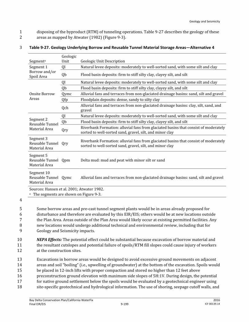
Geology and Seismicity
Bay Delta Conservation Plan/California WaterFix Final EIR/EIS
Administrative Final 9-199
2016 ICF 00139.14
disposing of the byproduct (RTM) of tunneling operations. Table 9-27 describes the geology of these 1 areas as mapped by Atwater (1982) (Figure 9-3). 2
Table 9-27. Geology Underlying Borrow and Reusable Tunnel Material Storage Areas—Alternative 4 3
Segmenta Geologic Unit Geologic Unit Description
Segment 1 Borrow and/or Spoil Area
Ql Natural levee deposits: moderately to well-sorted sand, with some silt and clay
Qb Flood basin deposits: firm to stiff silty clay, clayey silt, and silt
Onsite Borrow Areas
Ql Natural levee deposits: moderately to well-sorted sand, with some silt and clay Qb Flood basin deposits: firm to stiff silty clay, clayey silt, and silt Qymc Alluvial fans and terraces from non-glaciated drainage basins: sand, silt and gravel Qfp Floodplain deposits: dense, sandy to silty clay
Qch Alluvial fans and terraces from non-glaciated drainage basins: clay, silt, sand, and gravel
Segment 2 Reusable Tunnel Material Area
Ql Natural levee deposits: moderately to well-sorted sand, with some silt and clay Qb Flood basin deposits: firm to stiff silty clay, clayey silt, and silt
Qry Riverbank Formation: alluvial fans from glaciated basins that consist of moderately sorted to well-sorted sand, gravel, silt, and minor clay
Segment 3 Reusable Tunnel Material Area
Qry Riverbank Formation: alluvial fans from glaciated basins that consist of moderately sorted to well-sorted sand, gravel, silt, and minor clay
Segment 5 Reusable Tunnel Material Area
Qpm Delta mud: mud and peat with minor silt or sand
Segment 10 Reusable Tunnel Material Area
Qymc Alluvial fans and terraces from non-glaciated drainage basins: sand, silt and gravel
Sources: Hansen et al. 2001; Atwater 1982. a The segments are shown on Figure 9-3. 4
Some borrow areas and pre-cast tunnel segment plants would be in areas already proposed for 5 disturbance and therefore are evaluated by this EIR/EIS; others would be at new locations outside 6 the Plan Area. Areas outside of the Plan Area would likely occur at existing permitted facilities. Any 7 new locations would undergo additional technical and environmental review, including that for 8 Geology and Seismicity impacts. 9
NEPA Effects: The potential effect could be substantial because excavation of borrow material and 10 the resultant cutslopes and potential failure of spoils/RTM fill slopes could cause injury of workers 11 at the construction sites. 12
Excavations in borrow areas would be designed to avoid excessive ground movements on adjacent 13 areas and soil “boiling” (i.e., upwelling of groundwater) at the bottom of the excavation. Spoils would 14 be placed in 12-inch lifts with proper compaction and stored no higher than 12 feet above 15 preconstruction ground elevation with maximum side slopes of 5H:1V. During design, the potential 16 for native ground settlement below the spoils would be evaluated by a geotechnical engineer using 17 site-specific geotechnical and hydrological information. The use of shoring, seepage cutoff walls, and 18

Geology and Seismicity
Bay Delta Conservation Plan/California WaterFix Final EIR/EIS
Administrative Final 9-200
2016 ICF 00139.14
ground modifications to prevent slope instability, soil boiling, or excessive settlement would be 1 considered in the design. As described in Section 9.3.1, Methods for Analysis, the measures would 2 conform to applicable design and building codes, guidelines, and standards, such as the California 3 Building Code and USACE‘s Engineering and Design—Structural Design and Evaluation of Outlet 4 Works. 5
In addition to the risk of slope failure at borrow sites and spoils and RTM sites, there are also 6 potential impacts on levee stability resulting from construction of Alternative 4 water conveyance 7 facilities. The intake facilities would be sited along the existing Sacramento River levee system, 8 requiring reconstruction of levees and construction of a perimeter levee/building pad to provide 9 continued flood management. 10
As discussed in Chapter 3, Description of the Alternatives, the new perimeter levee/building pad 11 would be designed to provide an adequate Sacramento River channel cross section and to provide 12 the same level of flood protection as the existing levee and would be constructed to geometries that 13 exceed PL 84-99 standards. The design of the levee/building pad height would consider potential 14 wind and wave erosion. The elevation of the levee/building pad crest would provide adequate 15 freeboard above anticipated water surface elevations. Depending on the foundation material at each 16 intake facility, foundation improvements would entail excavation and replacement of soil below the 17 new levee/building pad footprint and potential ground improvement. The levee/building pad 18 height, as measured from the adjacent ground surface on the landside vertically up to the elevation 19 of the berm crest, would range from approximately 20 to 45 feet to provide adequate freeboard 20 above anticipated water surface elevations. The width of the perimeter levee/berm (toe of berm to 21 toe of berm) would range from approximately 180 to 360 feet. The minimum crest width of the 22 berm would be 20 feet; however, in some places it would be larger to accommodate roadways and 23 other features. A cut-off wall would be constructed along the perimeter of the forebay part of the 24 intake facility to avoid seepage, and the minimum slope of the levee walls/building pad would be 25 three units horizontal to one unit vertical. All levee reconstruction/building pad construction would 26 conform to applicable state and federal flood management engineering and permitting 27 requirements. 28
The levees would be armored with riprap—small to large angular boulders—on the waterside. 29 Intakes would be constructed using a sheetpile cofferdam in the river to create a dewatered 30 construction area that would encompass the intake site. The cofferdam would lie approximately 10–31 35 feet from the footprint of the intake and would be built from upstream to downstream, with the 32 downstream end closed last. The distance between the face of the intake and the face of the 33 cofferdam would be dependent on the foundation design and overall dimensions. The length of each 34 temporary cofferdam would vary by intake location, but would range from 740 to 2,440 feet. The 35 cofferdams would be supported by steel sheet piles and/or king piles (heavy H-section steel piles). 36 Installation of these piles may require both impact and vibratory pile drivers. Some clearing and 37 grubbing of levees would be required prior to installation of the sheet pile cofferdam, depending on 38 site conditions. Additionally, if stone bank protection, riprap, or mature vegetation is present at 39 intake construction site, it would be removed prior to sheet pile installation. DWR would ensure that 40 the geotechnical design recommendations are included in the design of project facilities and 41 construction specifications and are properly executed during construction to minimize the potential 42 effects from failure of excavations. DWR has made this conformance and monitoring process an 43 environmental commitment of the BDCP (see Appendix 3B, Environmental Commitments, AMMs, and 44 CMs). 45

Geology and Seismicity
Bay Delta Conservation Plan/California WaterFix Final EIR/EIS
Administrative Final 9-201
2016 ICF 00139.14
In particular, conformance with the following codes and standards would reduce the potential risk 1 for increased likelihood of loss of property or personal injury from settlement/failure of cutslopes of 2 borrow sites and failure of soil or RTM fill slopes during construction. 3
DWR Division of Engineering State Water Project—Seismic Loading Criteria Report, September 4 2012. 5
DWR Division of Flood Management FloodSAFE Urban Levee Design Criteria, May 2012. 6
8 CCR Sections 1509 and 3203. 7
Generally, the applicable codes require that facilities be built to certain factors of safety in order to 8 ensure that facilities perform as designed for the life of the structure despite various soil 9 parameters. The worker safety codes and standards specify protective measures that must be taken 10 at construction sites to minimize the risk of injury or death from structural or earth failure (e.g., 11 utilizing personal protective equipment, practicing crane and scaffold safety measures). The 12 relevant codes and standards represent performance standards that must be met by contractors and 13 these measures are subject to monitoring by state and local agencies. Cal-OSHA requirements for an 14 IIPP and the terms of the IIPP to protect worker safety are the principal measures that would be 15 enforced at construction sites. 16
Conformance to these and other applicable design specifications and standards would ensure that 17 construction of Alternative 4 would not create an increased likelihood of loss of property, personal 18 injury or death of individuals from slope failure at borrow sites and spoils and RTM storage sites. 19 The maintenance and reconstruction of levees would improve levee stability over existing 20 conditions due to improved side slopes, erosion control measures (geotextile fabrics, rock 21 revetments, or other material), seepage reduction measures, and overall mass. Therefore, there 22 would be no adverse effect. 23
CEQA Conclusion: Settlement/failure of cutslopes of borrow sites and failure of soil/RTM fill slopes 24 could result in loss of property or personal injury during construction. However, because DWR 25 would conform to Cal-OSHA and other state code requirements and conform to applicable 26 geotechnical design guidelines and standards, such as USACE design measures, the hazard would be 27 controlled to a safe level and there would be no increased likelihood of loss of property, personal 28 injury or death due to construction of Alternative 4 at borrow sites and spoils and RTM storage sites. 29 The maintenance and reconstruction of levees would improve levee stability over existing 30 conditions due to improved side slopes, erosion control measures, seepage reduction measures, and 31 overall mass. The impact would be less than significant. No mitigation is required. 32
Impact GEO-5: Loss of Property, Personal Injury, or Death from Structural Failure Resulting 33 from Construction-Related Ground Motions during Construction of Water Conveyance 34 Features 35
Pile driving and other heavy equipment operations would cause vibrations that could initiate 36 liquefaction and associated ground movements in places where soil and groundwater conditions are 37 present to allow liquefaction to occur. The consequences of liquefaction could be manifested in 38 terms of compaction or settlement, loss of bearing capacity, lateral spreading (horizontal soil 39 movement), increased lateral soil pressure, and buoyancy within zones of liquefaction. These 40 consequences could damage nearby structures and levees. 41

Geology and Seismicity
Bay Delta Conservation Plan/California WaterFix Final EIR/EIS
Administrative Final 9-202
2016 ICF 00139.14
The lateral extent (or influenced distance) of damage potential caused by pile driving and heavy 1 equipment operations depends on many factors, including soil conditions, the piling hammer used, 2 frequency of piling, and the vibration tolerance of structures and levees. 3
Pile driving would be conducted at the intakes, where, based on boring logs, soil materials subject to 4 liquefaction (e.g., saturated, poorly graded sand) are present. In addition to pile driving activities, 5 construction of the water conveyance facilities would require an increased volume of truck and 6 heavy equipment traffic that may occur at some of these locations. Although the trucks and heavy 7 equipment could generate vibrations in the levees, the severity of the vibrations is not expected to 8 be capable of initiating liquefaction. Construction related to conveyance facilities would also require 9 regular access to construction sites, extending the length of the project. Some of the existing public 10 roads would be used as haul routes for the construction of conveyance facilities. Use of the state 11 highway system as haul routes would be maximized where feasible because these roadways are 12 rated for truck traffic and would generally provide the most direct and easily maneuverable routes 13 for large loads. As part of future engineering phases, haul routes needed for the construction of the 14 approved project would be refined. Construction traffic may need to access levee roads at various 15 points along SR 160 and other state routes as shown in Figure 9-7, as well as at locations shown 16 along the Modified Pipeline/Tunnel Alignment in Figure 9-8b. Because of the volume of truck traffic 17 that may occur at some of these locations, there is the potential for some effect on levee integrity at 18 various locations depending on the site specific levee conditions along access routes. 19
During project design, site-specific geotechnical and groundwater investigations would be 20 conducted to build upon existing data (e.g., California Department of Water Resources 2010a, 21 2010b, 2011) to identify and characterize the vertical (depth) and horizontal (spatial) variability in 22 soil bearing capacity and extent of liquefiable soil. Engineering soil parameters that could be used to 23 assess the liquefaction potential, such as (SPT) blow counts, (CPT) penetration tip 24 pressure/resistance, and gradation of soil, would also be obtained. SPT blow counts and CPT tip 25 pressure are used to estimate soil resistance to cyclic loadings by using empirical relationships that 26 were developed based on occurrences of liquefaction (or lack of them) during past earthquakes. 27 The resistance then can be compared to cyclic shear stress induced by the design earthquake (i.e., 28 the earthquake that is expected to produce the strongest level of ground shaking at a site to which it 29 is appropriate to design a structure to withstand). If soil resistance is less than induced stress, the 30 potential of having liquefaction during the design earthquakes is high. It is also known that soil with 31 high “fines” (i.e., silt- and clay-sized particles) content are less susceptible to liquefaction. 32
NEPA Effects: The potential effect could be substantial because construction-related ground motions 33 could initiate liquefaction, which could cause failure of structures during construction, which could 34 result in injury of workers at the construction sites. Some of the potential levee effects that could 35 occur during the construction in the absence of corrective measures may include rutting, settlement, 36 and slope movement. 37
During design, the facility-specific potential for liquefaction would be investigated by a geotechnical 38 engineer. The investigations are an environmental commitment of the BDCP (see Appendix 3B, 39 Environmental Commitments, AMMs, and CMs). The potential effects of construction vibrations on 40 nearby structures, levees, and utilities would be evaluated using specific piling information (such as 41 pile type, length, spacing, and pile-driving hammer to be used). In areas determined to have a 42 potential for liquefaction, the California-registered civil engineer or California-certified engineering 43 geologist would develop design strategies and construction methods to ensure that pile driving and 44
Geology and Seismicity
Bay Delta Conservation Plan/California WaterFix Final EIR/EIS
Administrative Final 9-203
2016 ICF 00139.14
heavy equipment operations do not cause liquefaction which otherwise could damage facilities 1 under construction and surrounding structures, and could threaten the safety of workers at the site. 2
As shown in Figure 9-6, the Alternative 4 alignment extends through areas that generally have a 3 medium or high vulnerability for seismically induced levee failure, with a high risk of liquefaction at 4 intakes 2 and 5 (California Department of Water Resources 2015). Figure 9-6 shows that four of the 5 five barge unloading facilities would be located on levees with a high vulnerability to seismically 6 induced failure; the fifth (the northernmost) has a low vulnerability. Design measures to avoid pile-7 driving induced levee failure may include predrilling or jetting, using open-ended pipe piles to 8 reduce the energy needed for pile penetration, using CIDH piles/piers that do not require driving, 9 using pile jacking to press piles into the ground by means of a hydraulic system, or driving piles 10 during the drier summer months. Field data collected during design also would be evaluated to 11 determine the need for and extent of strengthening levees, embankments, and structures to reduce 12 the effect of vibrations. These construction methods would conform to current seismic design codes 13 and requirements, as described in Appendix 3B, Environmental Commitments, AMMs, and CMs. Such 14 design standards include USACE‘s Engineering and Design—Stability Analysis of Concrete Structures 15 and Soil Liquefaction during Earthquakes, by the Earthquake Engineering Research Institute. 16
As with the effects related to design of conveyance facilities, potential construction traffic effects on 17 levees would be assessed prior to project construction to determine specific geotechnical issues 18 related to construction traffic loading. Based on the initial assessment from field reconnaissance, 19 geotechnical exploration and analyses would be performed for levee sections that need further 20 evaluations. Should the geotechnical evaluations indicate that certain segments of existing levee 21 roads need improvements to carry the expected construction truck traffic loads, DWR is committed 22 to carry out the necessary improvements to the affected levee sections or to find an alternative route 23 that would avoid the potential deficient levee sections (Mitigation Measures TRANS-2a through 2c). 24 As discussed in Chapter 19, Transportation, Mitigation Measure TRANS-2c, all affected roadways 25 would be returned to preconstruction condition or better following construction. Implementation of 26 this measure would ensure that construction activities would not worsen pavement and levee 27 conditions, relative to existing conditions. Prior to construction, DWR would make a good faith effort 28 to enter into mitigation agreements with or to obtain encroachment permits from affected agencies 29 to verify what the location, extent, timing, and fair share cost to be paid by the DWR for any 30 necessary pre- and post-construction physical improvements. Levee roads that are identified as 31 potential haul routes and expected to carry significant construction truck traffic would be monitored 32 to ensure that truck traffic is not adversely affecting the levee and to identify the need for corrective 33 action. 34
DWR has made the environmental commitment (see Appendix 3B, Environmental Commitments, 35 AMMs, and CMs) that the construction methods recommended by the geotechnical engineer are 36 included in the design of project facilities and construction specifications to minimize the potential 37 for construction-induced liquefaction. DWR also has committed to ensure that these methods are 38 followed during construction. 39
In particular, conformance with the following codes and standards would reduce the potential risk 40 for increased likelihood of loss of property or personal injury from structural failure resulting from 41 construction-related ground motions. 42
USACE Engineering and Design—Design of Pile Foundations, EM 1110-2-2906, 1991. 43

Geology and Seismicity
Bay Delta Conservation Plan/California WaterFix Final EIR/EIS
Administrative Final 9-204
2016 ICF 00139.14
USACE Engineering and Design—Earthquake Design and Evaluation for Civil Works Projects, 1 ER 1110-2-1806, 1995. 2
8 CCR Sections 1509 and 3203. 3
Generally, the applicable codes require that facilities be built so that if soil in the foundation or 4 surrounding area are subject to liquefaction, the removal or densification of the liquefiable material 5 should be considered, along with alternative foundation designs. Additionally, any modification to a 6 federal levee system would require USACE approval under 33 USC 408 (a 408 Permit). 7
The worker safety codes and standards specify protective measures that must be taken at 8 construction sites to minimize the risk of injury or death from structural or earth failure (e.g., 9 utilizing personal protective equipment, practicing crane and scaffold safety measures). The 10 relevant codes and standards represent performance standards that must be met by contractors and 11 these measures are subject to monitoring by state and local agencies. Cal-OSHA requirements for an 12 IIPP and the terms of the IIPP to protect worker safety are the principal measures that would be 13 enforced at construction sites. 14
Conformance to construction method recommendations and other applicable specifications, as well 15 as implementation of Mitigation Measures TRANS-2a through 2c, would ensure that construction of 16 Alternative 4 would not create an increased likelihood of loss of property, personal injury or death 17 of individuals due to construction- and traffic-related ground motions and resulting potential 18 liquefaction in the work area. Therefore, there would be no adverse effect. 19
CEQA Conclusion: Construction-related ground motions and traffic effects could initiate 20 liquefaction, which could cause failure of structures during construction. The impact could be 21 significant. However, because DWR would conform to Cal-OSHA and other state code requirements 22 and conform to applicable design guidelines and standards, such as USACE design measures, in 23 addition to implementation of Mitigation Measures TRANS-2a and TRANS-2b, as well as the 24 maintenance and reconstruction of levees through Mitigation Measure TRANS-2c, the hazard would 25 be controlled to a level that would protect worker safety (see Appendix 3B, Environmental 26 Commitments, AMMs, and CMs). Further, DWR has made an environmental commitment (see 27 Appendix 3B) that the construction methods recommended by the geotechnical engineer are 28 included in the design of project facilities and construction specifications to minimize the potential 29 for construction-induced liquefaction. DWR also has committed to ensure that these methods are 30 followed during construction. Proper execution of these environmental commitments would result 31 in no increased likelihood of loss of property, personal injury or death due to construction of 32 Alternative 4. The impact would be less than significant. 33
Mitigation Measure TRANS-2a: Prohibit Construction Activity on Physically Deficient 34 Roadway Segments 35
Please refer to Mitigation Measure TRANS-2a in Alternative 1A, Impact TRANS-2, in Chapter 19, 36 Transportation. 37
Mitigation Measure TRANS-2b: Limit Construction Activity on Physically Deficient 38 Roadway Segments 39
Please refer to Mitigation Measure TRANS-2b in Alternative 1A, Impact TRANS-2, in Chapter 19, 40 Transportation. 41
Geology and Seismicity
Bay Delta Conservation Plan/California WaterFix Final EIR/EIS
Administrative Final 9-205
2016 ICF 00139.14
Mitigation Measure TRANS-2c: Improve Physical Condition of Affected Roadway Segments 1 as Stipulated in Mitigation Agreements or Encroachment Permits 2
Please refer to Mitigation Measure TRANS-2c in Alternative 1A, Impact TRANS-2, in Chapter 19, 3 Transportation. 4
Impact GEO-6: Loss of Property, Personal Injury, or Death from Structural Failure Resulting 5 from Rupture of a Known Earthquake Fault during Operation of Water Conveyance Features 6
According to the available AP Fault Zone Maps, none of the Alternative 4 facilities would cross or be 7 within any known active fault zones. However, numerous AP fault zones have been mapped west of 8 the conveyance alignment (Figure 9-5). The closest AP fault zone would be the Greenville fault, 9 located approximately 7.6 miles west of the conveyance facilities. Because none of the Alternative 4 10 constructed facilities would be within any of the fault zones (which include the area approximately 11 200 to 500 feet on each side of the mapped surface trace to account for potential branches of active 12 faults), the potential that the facilities would be directly subject to fault offsets is negligible. 13
In the Delta, active or potentially active blind thrust faults were identified in the seismic study. 14 Segments 3 and 4 of the Alternative 4 conveyance alignment (which is the same as the Modified 15 Pipeline/Tunnel Alignment in Figure 9-3) would cross the Thornton Arch fault zone. The western 16 part of the proposed expanded Clifton Court Forebay is underlain by the West Tracy fault. Although 17 these blind thrusts are not expected to rupture to the ground surface under the forebays during 18 earthquake events, they may produce ground or near-ground shear zones, bulging, or both 19 (California Department of Water Resources 2007a). If the West Tracy fault is potentially active, it 20 could cause surface deformation in the western part of the existing Clifton Court Forebay. Because 21 the western part of the expanded Clifton Court Forebay is also underlain by the hanging wall of the 22 fault, this part of the forebay may also experience uplift and resultant surface deformation (Fugro 23 Consultants 2011). In the seismic study (California Department of Water Resources 2007a), the 24 Thornton Arch and West Tracy blind thrusts have been assigned 20% and 90% probabilities of 25 being active, respectively. The depth to the Thornton Arch blind thrust is unknown. The seismic 26 study indicates that the West Tracy fault dies out as a discernible feature within approximately 27 3,000 to 6,000 feet bgs [in the upper 1- to 2-second depth two-way time, estimated to be 28 approximately 3,000 to 6,000 feet using the general velocity function as published in the Association 29 of Petroleum Geologists Pacific Section newsletter (Tolmachoff 1993)]. 30
It appears that the potential of having any shear zones, bulging, or both at the depths of the modified 31 pipeline/tunnel is low because the depth to the blind thrust faults is generally deep and there is no 32 credible evidence to indicate that the faults could experience displacement within the depth of the 33 modified pipeline/tunnel. 34
NEPA Effects: The effect would not be adverse because no active faults extend into the Alternative 4 35 alignment. Additionally, although the Thornton Arch and West Tracy blind thrusts occur beneath the 36 Alternative 4 alignment, they do not present a hazard of surface rupture based on available 37 information, including the AP Earthquake Fault Zone Map showing faults capable of surface rupture 38 (Figure 9-5). 39
However, because there is limited information regarding the depths of the Thornton Arch and West 40 Tracy blind thrusts, seismic surveys would be performed on the blind thrust during the design phase 41 to determine the depths to the top of the faults. More broadly, design-level geotechnical studies 42 would be prepared by a geotechnical engineer licensed in the state of California during project 43

Geology and Seismicity
Bay Delta Conservation Plan/California WaterFix Final EIR/EIS
Administrative Final 9-206
2016 ICF 00139.14
design. The studies would further assess site-specific conditions at and near all the project facility 1 locations, including seismic activity, soil liquefaction, and other potential geologic and soil-related 2 hazards. This information would be used to verify assumptions and conclusions included in the 3 EIR/EIS. Consistent with the BDCP’s environmental commitments (see Appendix 3B, Environmental 4 Commitments, AMMs, and CMs), DWR would ensure that the geotechnical engineer’s recommended 5 measures to address adverse conditions would conform to applicable design codes, guidelines, and 6 standards, would be included in the project design and construction specifications, and would be 7 properly executed during construction. Potential design strategies or conditions could include 8 avoidance (deliberately positioning structures and lifelines to avoid crossing identified shear 9 rupture zones), geotechnical engineering (using the inherent capability of unconsolidated 10 geomaterials to “locally absorb” and distribute distinct bedrock fault movements) and structural 11 engineering (engineering the facility to undergo some limited amount of ground deformation 12 without collapse or significant damage). 13
As described in Section 9.3.1, Methods for Analysis, such conformance with design codes, guidelines, 14 and standards are environmental commitments by DWR (see Appendix 3B, Environmental 15 Commitments, AMMs, and CMs). For construction of the water conveyance facilities, the codes and 16 standards would include the California Building Code and resource agency and professional 17 engineering specifications, such as the Division of Safety of Dams’ Guidelines for Use of the 18 Consequence-Hazard Matrix and Selection of Ground Motion Parameters, DWR’s Division of Flood 19 Management FloodSAFE Urban Levee Design Criteria, and USACE‘s Engineering and Design—20 Earthquake Design and Evaluation for Civil Works Projects. These codes and standards include 21 minimum performance standards for structural design, given site-specific subsurface conditions. 22
DWR would ensure that the geotechnical design recommendations are included in the design of 23 project facilities and construction specifications to minimize the potential effects from seismic 24 events and the presence of adverse soil conditions. DWR would also ensure that the design 25 specifications are properly executed during construction. 26
In particular, conformance with the following codes and standards would reduce the potential risk 27 for increased likelihood of loss of property or personal injury from structural failure resulting from 28 surface rupture resulting from a seismic event during operation. 29
DWR Division of Engineering State Water Project—Seismic Loading Criteria Report, September 30 2012. 31
USACE Engineering and Design—Time-History Dynamic Analysis of Concrete Hydraulic Structures, 32 EM 1110-2-6051, 2003. 33
USACE Engineering and Design—Response Spectra and Seismic Analysis for Concrete Hydraulic 34 Structures, EM 1110-2-6050, 1999. 35
American Society of Civil Engineers Minimum Design Loads for Buildings and Other Structures, 36 ASCE/SEI 7-10, 2010. 37
8 CCR 3203. 38
Generally, the applicable codes require that facilities be built so that they incur minimal damage in 39 the event of a foreseeable seismic event and that they remain functional following such an event and 40 that the facility is able to perform without catastrophic failure in the event of a maximum design 41 earthquake (the greatest earthquake reasonably expected to be generated by a specific source on 42 the basis of seismological and geological evidence). 43
Geology and Seismicity
Bay Delta Conservation Plan/California WaterFix Final EIR/EIS
Administrative Final 9-207
2016 ICF 00139.14
The worker safety codes and standards specify protective measures that must be taken at 1 workplaces to minimize the risk of injury or death from structural or earth failure (e.g., utilizing 2 personal protective equipment). The relevant codes and standards represent performance 3 standards that must be met by workplaces and these measures are subject to monitoring by state 4 and local agencies. Cal-OSHA requirements for an IIPP and the terms of the IIPP to protect worker 5 safety are the principal measures that would be enforced at workplaces 6
Conformance to these and other applicable design specifications and standards would ensure that 7 operation of Alternative 4 would not create an increased likelihood of loss of property, personal 8 injury or death of individuals in the event of ground movement in the vicinity of the Thornton Arch 9 fault zone and West Tracy blind thrust. Therefore, such ground movements would not jeopardize 10 the integrity of the surface and subsurface facilities along the Alternative 4 conveyance alignment or 11 the proposed expanded Clifton Court Forebay and associated facilities adjacent to the existing 12 Clifton Court Forebay. Therefore, there would be no adverse effect. 13
CEQA Conclusion: There are no active faults capable of surface rupture that extend into the 14 Alternative 4 modified pipeline/tunnel alignment. Although the Thornton Arch and West Tracy 15 blind thrusts occur beneath the Alternative 4 modified pipeline/tunnel alignment, based on 16 available information, they do not present a hazard of surface rupture and there would be no 17 increased likelihood of loss of property, personal injury or death due to operation of Alternative 4. 18 However, because there is limited information regarding the depths of the Thornton Arch and West 19 Tracy blind thrusts, seismic surveys would be performed on the blind thrust during the design phase 20 to determine the depths to the top of the faults. More broadly, design-level geotechnical studies 21 would be prepared by a geotechnical engineer licensed in the state of California during project 22 design. The studies would further assess site-specific conditions at and near all the project facility 23 locations, including seismic activity, soil liquefaction, and other potential geologic and soil-related 24 hazards. This information would be used to verify assumptions and conclusions included in the 25 EIR/EIS. Consistent with the BDCP’s environmental commitments (see Appendix 3B, Environmental 26 Commitments, AMMs, and CMs), DWR would ensure that the geotechnical engineer’s recommended 27 measures to address adverse conditions would conform to applicable design codes, guidelines, and 28 standards, would be included in the project design and construction specifications, and would be 29 properly executed during construction. Potential design strategies or conditions could include 30 avoidance (deliberately positioning structures and lifelines to avoid crossing identified shear 31 rupture zones), geotechnical engineering (using the inherent capability of unconsolidated 32 geomaterials to “locally absorb” and distribute distinct bedrock fault movements), and structural 33 engineering (engineering the facility to undergo some limited amount of ground deformation 34 without collapse or significant damage). 35
As described in Section 9.3.1, Methods for Analysis, such conformance with design codes, guidelines, 36 and standards are environmental commitments by DWR (see Appendix 3B, Environmental 37 Commitments, AMMs, and CMs). For construction of the water conveyance facilities, the codes and 38 standards would include the California Building Code and resource agency and professional 39 engineering specifications, such as the Division of Safety of Dams Guidelines for Use of the 40 Consequence-Hazard Matrix and Selection of Ground Motion Parameters, DWR’s Division of Flood 41 Management FloodSAFE Urban Levee Design Criteria, and USACE‘s Engineering and Design—42 Earthquake Design and Evaluation for Civil Works Projects. These codes and standards include 43 minimum performance standards for structural design, given site-specific subsurface conditions. 44 Conformance to these and other applicable design specifications and standards would ensure that 45 operation of Alternative 4 would not create an increased likelihood of loss of property, personal 46
Geology and Seismicity
Bay Delta Conservation Plan/California WaterFix Final EIR/EIS
Administrative Final 9-208
2016 ICF 00139.14
injury or death of individuals in the event of ground movement in the vicinity of the Thornton Arch 1 fault zone and West Tracy blind thrust. Therefore, such ground movements would not jeopardize 2 the integrity of the surface and subsurface facilities along the Alternative 4 conveyance alignment or 3 the proposed expanded Clifton Court Forebay and associated facilities adjacent to the existing 4 Clifton Court Forebay. There would be no impact. No mitigation is required. 5
Impact GEO-7: Loss of Property, Personal Injury, or Death from Structural Failure Resulting 6 from Strong Seismic Shaking during Operation of Water Conveyance Features 7
Earthquake events may occur on the local and regional seismic sources during operation of the 8 Alternative 4 water conveyance facilities. The ground shaking could damage pipelines, tunnels, 9 intake facilities, pumping plants, and other facilities, disrupting the water supply through the 10 conveyance system. In an extreme event of strong seismic shaking, uncontrolled release of water 11 from damaged pipelines, tunnels, intake facilities, pumping plant, and other facilities could cause 12 flooding, disruption of water supplies to the south, and inundation of structures. These effects are 13 discussed more fully in Appendix 3E, Potential Seismicity and Climate Change Risks to SWP/CVP 14 Water Supplies. 15
Table 9-17 lists the expected PGA and 1.0-Sa values in 2025 at selected facility locations along the 16 pipeline/tunnel alignment. Alternative 4 would include the same physical/structural components as 17 Alternative 1A, but would entail two less intakes and five less pumping plants. These differences 18 would present a slightly lower hazard of seismic shaking but would not substantially change the 19 hazard of loss of property or personal injury during construction compared to Alternative 1A. 20
For early long-term, earthquake ground motions with return periods of 144 years and 975 years 21 were estimated from the results presented in the seismic study (California Department of Water 22 Resources 2007a). The 144-year and 975-year ground motions correspond to the OBE (i.e., an 23 earthquake that has a 50% probability of exceedance in a 100-year period (which is equivalent to a 24 144-year return period event) and the MDE (i.e., an earthquake that causes ground motions that 25 have a 10% chance of being exceeded in 100 years) design ground motions, respectively. Values 26 were estimated for a stiff soil site (as predicted in the seismic study), and for the anticipated soil 27 conditions at the facility locations. No seismic study results exist for 2025, so the ground shaking 28 estimated for the 2050 were used for Early Long-term (2025). 29
Table 9-17 shows that the proposed facilities would be subject to moderate-to-high earthquake 30 ground shaking through 2025. All facilities would be designed and constructed in accordance with 31 the requirements of the design guidelines and building codes described in Appendix 3B, 32 Environmental Commitments, AMMs, and CMs. Site-specific geotechnical information would be used 33 to further assess the effects of local soil on the OBE and MDE ground shaking and to develop design 34 criteria that minimize damage potential. 35
NEPA Effects: This potential effect could be substantial because strong ground shaking could 36 damage pipelines, tunnels, intake facilities, pumping plant, and other facilities and result in loss of 37 property or personal injury. The damage could disrupt the water supply through the conveyance 38 system. In an extreme event, an uncontrolled release of water from the conveyance system could 39 cause flooding and inundation of structures. Please refer to Chapter 6, Surface Water, and Appendix 40 3E, Potential Seismicity and Climate Change Risks to SWP/CVP Water Supplies, for a detailed 41 discussion of potential flood effects. 42

Geology and Seismicity
Bay Delta Conservation Plan/California WaterFix Final EIR/EIS
Administrative Final 9-209
2016 ICF 00139.14
The structure of the underground conveyance facility would decrease the likelihood of loss of 1 property or personal injury of individuals from structural shaking of surface and subsurface 2 facilities along the Alternative 4 conveyance alignment in the event of strong seismic shaking. The 3 conveyance pipeline would be lined with precast concrete which would be installed continuously 4 following the advancement of a pressurized tunnel boring machine. The lining consists of precast 5 concrete segments inter-connected to maintain alignment and structural stability during 6 construction. Reinforced concrete segments are precast to comply with strict quality control. High 7 performance gasket maintains water tightness at the concrete joints, while allowing the joint to 8 rotate and accommodate movements during intense ground shaking. PCTL has been used 9 extensively in seismically active locations such as Japan, Puerto Rico, Taiwan, Turkey, Italy and 10 Greece. The adoption of PCTL in the United States started about 20 years ago, including many 11 installations in seismically active areas such as Los Angeles, San Diego, Portland and Seattle. PCTL 12 provides better seismic performance than conventional tunnels for several reasons: 13
higher quality control using precast concrete 14
better ring-build precision with alignment connectors 15
backfill grouting for continuous ground to tunnel support 16
segment joints provide flexibility and accommodate deformation during earthquakes 17
high performance gasket to maintain water tightness during and after seismic movement 18
Reviewing the last 20 years of PCTL seismic performance histories, it can be concluded that little or 19 no damage to PCTL was observed for major earthquakes around the world. Case studies of the 20 response of PCTL to large seismic events have shown that PCTL should not experience significant 21 damage for ground acceleration less than 0.5g (Dean et al. 2006). The design PGA for a 975-year 22 return period is 0.49g (California Department of Water Resources 2010i:Table 4-4). Based on this 23 preliminary data, the Delta tunnels can be designed to withstand the anticipated seismic loads. 24
In accordance with the DWR’s environmental commitments (see Appendix 3B, Environmental 25 Commitments, AMMs, and CMs), design-level geotechnical studies would be conducted by a licensed 26 civil engineer who practices in geotechnical engineering. The studies would assess site-specific 27 conditions at and near all the project facility locations and provide the basis for designing the 28 conveyance features to withstand the peak ground acceleration caused by fault movement in the 29 region. The California-registered civil engineer or California-certified engineering geologist’s 30 recommended measures to address this hazard would conform to applicable design codes, 31 guidelines, and standards. As described in Section 9.3.1, Methods for Analysis, and in Appendix 3B, 32 such design codes, guidelines, and standards include the California Building Code and resource 33 agency and professional engineering specifications, such as the Division of Safety of Dams Guidelines 34 for Use of the Consequence-Hazard Matrix and Selection of Ground Motion Parameters, DWR‘s 35 Division of Flood Management FloodSAFE Urban Levee Design Criteria, and USACE‘s Engineering and 36 Design—Earthquake Design and Evaluation for Civil Works Projects. Conformance with these codes 37 and standards are an environmental commitment by DWR to ensure that ground shaking risks are 38 minimized as the water conveyance features are operated. 39
DWR would ensure that the geotechnical design recommendations are included in the design of 40 project facilities and construction specifications to minimize the potential effects from seismic 41 events and the presence of adverse soil conditions. DWR would also ensure that the design 42

Geology and Seismicity
Bay Delta Conservation Plan/California WaterFix Final EIR/EIS
Administrative Final 9-210
2016 ICF 00139.14
specifications are properly executed during construction. See Appendix 3B, Environmental 1 Commitments, AMMs, and CMs. 2
In particular, conformance with the following codes and standards would reduce the potential risk 3 for increased likelihood of loss of property or personal injury from structural failure resulting from 4 strong seismic shaking of water conveyance features during operations. 5
DWR Division of Engineering State Water Project—Seismic Loading Criteria Report, September 6 2012. 7
USACE Engineering and Design—Time-History Dynamic Analysis of Concrete Hydraulic Structures, 8 EM 1110-2-6051, 2003. 9
USACE Engineering and Design—Response Spectra and Seismic Analysis for Concrete Hydraulic 10 Structures, EM 1110-2-6050, 1999. 11
American Society of Civil Engineers Minimum Design Loads for Buildings and Other Structures, 12 ASCE/SEI 7-10, 2010. 13
8 CCR 3203. 14
Generally, the applicable codes require that facilities be built so that they incur minimal damage in 15 the event of a foreseeable seismic event and that they remain functional following such an event and 16 that the facility is able to perform without catastrophic failure in the event of a maximum design 17 earthquake (the greatest earthquake reasonably expected to be generated by a specific source on 18 the basis of seismological and geological evidence). 19
The worker safety codes and standards specify protective measures that must be taken at 20 workplaces to minimize the risk of injury or death from structural or earth failure (e.g., utilizing 21 personal protective equipment). The relevant codes and standards represent performance 22 standards that must be met by employers and these measures are subject to monitoring by state and 23 local agencies. Cal-OSHA requirements for an IIPP and the terms of the IIPP to protect worker safety 24 are the principal measures that would be enforced at workplaces during operations. 25
Conformance to these and other applicable design specifications and standards would ensure that 26 operation of Alternative 4 would not create an increased likelihood of loss of property, personal 27 injury or death of individuals from structural shaking of surface and subsurface facilities along the 28 Alternative 4 conveyance alignment in the event of strong seismic shaking. Therefore, there would 29 be no adverse effect. 30
CEQA Conclusion: Seismically induced strong ground shaking could damage pipelines, tunnels, 31 intake facilities, pumping plant, and other facilities. The damage could disrupt the water supply 32 through the conveyance system. In an extreme event, an uncontrolled release of water from the 33 damaged conveyance system could cause flooding and inundation of structures. (Please refer to 34 Chapter 6, Surface Water, for a detailed discussion of potential flood impacts.) However, through the 35 final design process, which would be supported by geotechnical investigations required by DWR’s 36 environmental commitments (see Appendix 3B, Environmental Commitments, AMMs, and CMs), 37 measures to address this hazard would be required to conform to applicable design codes, 38 guidelines, and standards. As described in Section 9.3.1, Methods for Analysis, and in Appendix 3B, 39 such design codes, guidelines, and standards include the California Building Code and resource 40 agency and professional engineering specifications, such as the Division of Safety of Dams’ Guidelines 41 for Use of the Consequence-Hazard Matrix and Selection of Ground Motion Parameters, DWR‘s 42

Geology and Seismicity
Bay Delta Conservation Plan/California WaterFix Final EIR/EIS
Administrative Final 9-211
2016 ICF 00139.14
Division of Flood Management FloodSAFE Urban Levee Design Criteria, and USACE‘s Engineering and 1 Design—Earthquake Design and Evaluation for Civil Works Projects. Conformance with these codes 2 and standards is an environmental commitment by DWR to ensure that ground shaking risks are 3 minimized as the water conveyance features are operated. The hazard would be controlled to a safe 4 level and there would be no increased likelihood of loss of property, personal injury or death due to 5 operation of Alternative 4. The impact would be less than significant. No mitigation is required. 6
Impact GEO-8: Loss of Property, Personal Injury, or Death from Structural Failure Resulting 7 from Seismic-Related Ground Failure (Including Liquefaction) during Operation of Water 8 Conveyance Features 9
Earthquake-induced ground shaking could cause liquefaction, resulting in soil slumping or lateral 10 spreading and subsequent damage to or breaching of water conveyance structures and facilities. The 11 consequences of liquefaction are manifested in terms of compaction or settlement, loss of bearing 12 capacity, lateral spreading (soil movement), increased lateral soil pressure, and buoyancy within 13 zones of liquefaction. Failure of tunnels, pipelines, levees, bridges, and other structures and facilities 14 could result in loss, injury, and disrupt SWP and CVP water supply deliveries. The potential for 15 impacts from flooding as a result of levee or dam failure is also discussed in Chapter 6, Surface 16 Water. 17
The native soil underlying Alternative 4 facilities consist of various channel deposits and recent silty 18 and sandy alluvium at shallow depths. The available data along the southern portion of the 19 conveyance (from approximately Potato Slough to Clifton Court Forebay) show that the recent 20 alluvium overlies peaty or organic soils, which in turn is underlain by layers of mostly sandy and 21 silty soil (Real and Knudsen 2009). Soil borings advanced by DWR along the northern portion of the 22 conveyance (from approximately Potato Slough to Intake 1) show the surface soil as being similar to 23 the range reported for the southern portion, but locally containing strata of clayey silt and lean clay. 24 Because the borings were made over water, peat was usually absent from the boring logs (California 25 Department of Water Resources 2011). 26
The silty and sandy soil deposits underlying the peaty and organic soil over parts of the Delta are 27 late-Pleistocene age dune sand, which are liquefiable during major earthquakes. The tops of these 28 materials are exposed in some areas, but generally lie beneath the peaty soil at depths of about 10–29 40 feet bgs along the modified pipeline/tunnel alignment (Real and Knudsen 2009). Liquefaction 30 hazard mapping by Real and Knudsen (2009), which covers only the southwestern part of the Plan 31 Area, including the part of the alignment from near Isleton to the Palm Tract, indicates that the 32 lateral ground deformation potential would range from <0.1 to 6.0 feet. Liquefaction-induced 33 ground settlement during the 1906 San Francisco earthquake was also reported near Alternative 4 34 facilities at a bridge crossing over Middle River just north of Woodward Island (Youd and Hoose 35 1978). Local variations in thickness and lateral extent of liquefiable soil may exist, and they may 36 have important influence on liquefaction-induced ground deformations. 37
Figure 9-6 shows that the northern part of the Alternative 4 alignment is outside the area (i.e., 38 outside the mean higher high water floodplain) within which levees were evaluated by DWR 39 (California Department of Water Resources 2008b) for their vulnerability to seismically induced 40 levee failure. The remainder of the alignment, extending south from approximately Courtland, 41 extends through areas in which the levees generally have a high or medium vulnerability to 42 seismically induced failure. 43

Geology and Seismicity
Bay Delta Conservation Plan/California WaterFix Final EIR/EIS
Administrative Final 9-212
2016 ICF 00139.14
Because the tunnel invert would be at depths of 100–160 feet bgs, the potential effect on these 1 facilities due to liquefaction is judged to be low. However, certain surface and near-surface facilities, 2 such as the pumping plant and Clifton Court forebay expansion area, would be constructed in areas 3 with medium or high vulnerability to failure from seismic shaking, as inferred from the levee seismic 4 vulnerability map (Figure 9-6). 5
NEPA Effects: The potential effect could be substantial because seismically induced ground shaking 6 could cause liquefaction, and damage pipelines, tunnels, intake facilities, pumping plant, and other 7 facilities. The damage could disrupt the water supply through the conveyance system. In an extreme 8 event, an uncontrolled release of water from the damaged conveyance system could cause flooding 9 and inundation of structures. Please refer to Appendix 3E, Potential Seismicity and Climate Change 10 Risks to SWP/CVP Water Supplies, for a detailed discussion of potential flooding effects. 11
In the process of preparing final facility designs, site-specific geotechnical and groundwater 12 investigations would be conducted to identify and characterize the vertical (depth) and horizontal 13 (spatial) extents of liquefiable soil. Engineering soil parameters that could be used to further assess 14 the liquefaction potential, such as SPT blow counts, CPT penetration tip pressure/resistance, and 15 gradation of soil, would also be obtained. SPT blow counts and CPT tip pressure are used to estimate 16 soil resistance to cyclic loadings by using empirical relationships that were developed based on 17 occurrences of liquefaction (or lack of them) during past earthquakes. The resistance then can be 18 compared to cyclic shear stress induced by the design earthquake. If soil resistance is less than 19 induced stress, the potential of having liquefaction during the design earthquakes is high. It is also 20 known that soil with high “fines” (i.e., silt- and clay-sized particles) content are less susceptible to 21 liquefaction. 22
During final design, site-specific potential for liquefaction would be investigated by a geotechnical 23 engineer. In areas determined to have a potential for liquefaction, a California-registered civil 24 engineer or California-certified engineering geologist would develop design measures and 25 construction methods to meet design criteria established by building codes and construction 26 standards to ensure that the design earthquake does not cause damage to or failure of the facility. 27 Such measures and methods include removing and replacing potentially liquefiable soil, 28 strengthening foundations (for example, using post-tensioned slab, reinforced mats, and piles) to 29 resist excessive total and differential settlements, and using in situ ground improvement techniques 30 (such as deep dynamic compaction, vibro-compaction, vibro-replacement, compaction grouting, and 31 other similar methods). The results of the site-specific evaluation and California-registered civil 32 engineer or California-certified engineering geologist’s recommendations would be documented in a 33 detailed geotechnical report prepared in accordance with state guidelines, in particular Guidelines 34 for Evaluating and Mitigating Seismic Hazards in California (California Geological Survey 2008). As 35 described in Section 9.3.1, Methods for Analysis, and in Appendix 3B, Environmental Commitments, 36 AMMs, and CMs, such design codes, guidelines, and standards include USACE‘s Engineering and 37 Design—Stability Analysis of Concrete Structures and Soil Liquefaction during Earthquakes, by the 38 Earthquake Engineering Research Institute. Conformance with these design requirements is an 39 environmental commitment by DWR to ensure that liquefaction risks are minimized as the water 40 conveyance features are operated. 41
DWR would ensure that the geotechnical design recommendations are included in the design of 42 project facilities and construction specifications to minimize the potential effects from liquefaction 43 and associated hazards. DWR would also ensure that the design specifications are properly executed 44 during construction. 45

Geology and Seismicity
Bay Delta Conservation Plan/California WaterFix Final EIR/EIS
Administrative Final 9-213
2016 ICF 00139.14
In particular, conformance with the following codes and standards would reduce the potential risk 1 for increased likelihood of loss of property or personal injury from structural failure resulting from 2 strong seismic shaking of water conveyance features during operations. 3
DWR Division of Engineering State Water Project—Seismic Loading Criteria Report, September 4 2012. 5
USACE Engineering and Design—Time-History Dynamic Analysis of Concrete Hydraulic Structures, 6 EM 1110-2-6051, 2003 7
USACE Engineering and Design—Response Spectra and Seismic Analysis for Concrete Hydraulic 8 Structures, EM 1110-2-6050, 1999. 9
American Society of Civil Engineers Minimum Design Loads for Buildings and Other Structures, 10 ASCE/SEI 7-10, 2010. 11
USACE Engineering and Design—Design of Pile Foundations, EM 1110-2-2906, 1991 12
8 CCR 3203. 13
Generally, the applicable codes require that facilities be built so that if soil in the foundation or 14 surrounding area are subject to liquefaction, the removal or densification of the liquefiable material 15 should be considered, along with alternative foundation designs. Additionally, any modification to a 16 federal levee system would require USACE approval under 33 USC 408 (a 408 Permit). 17
The worker safety codes and standards specify protective measures that must be taken at 18 workplaces to minimize the risk of injury or death from structural or earth failure (e.g., utilizing 19 personal protective equipment). The relevant codes and standards represent performance 20 standards that must be met by employers and these measures are subject to monitoring by state and 21 local agencies. Cal-OSHA requirements for an IIPP and the terms of the IIPP to protect worker safety 22 are the principal measures that would be enforced at workplaces during operations. 23
Conformance to these and other applicable design specifications and standards would ensure that 24 the hazard of liquefaction and associated ground movements would not create an increased 25 likelihood of loss of property, personal injury or death of individuals from structural failure 26 resulting from seismic-related ground failure along the Alternative 4 conveyance alignment during 27 operation of the water conveyance features. Therefore, the effect would not be adverse. 28
CEQA Conclusion: Seismically induced ground shaking could cause liquefaction. Liquefaction could 29 damage pipelines, tunnels, intake facilities, pumping plant, and other facilities, and thereby disrupt 30 the water supply through the conveyance system. In an extreme event, flooding and inundation of 31 structures could result from an uncontrolled release of water from the damaged conveyance system. 32 (Please refer to Chapter 6, Surface Water, for a detailed discussion of potential flood impacts.) 33 However, through the final design process, measures to address the liquefaction hazard would be 34 required to conform to applicable design codes, guidelines, and standards. As described in Section 35 9.3.1, Methods for Analysis, and in Appendix 3B, Environmental Commitments, AMMs, and CMs, such 36 design codes, guidelines, and standards include USACE‘s Engineering and Design—Stability Analysis 37 of Concrete Structures and Soil Liquefaction during Earthquakes, by the Earthquake Engineering 38 Research Institute. Conformance with these design standards is an environmental commitment by 39 DWR to ensure that liquefaction risks are minimized as the water conveyance features are operated. 40 The hazard would be controlled to a safe level and there would be no increased likelihood of loss of 41

Geology and Seismicity
Bay Delta Conservation Plan/California WaterFix Final EIR/EIS
Administrative Final 9-214
2016 ICF 00139.14
property, personal injury or death due to operation of Alternative 4. The impact would be less than 1 significant. No mitigation is required. 2
Impact GEO-9: Loss of Property, Personal Injury, or Death from Landslides and Other Slope 3 Instability during Operation of Water Conveyance Features 4
Alternative 4 would involve excavation that creates new cut-and-fill slopes and construction of new 5 embankments and levees. As a result of ground shaking and high soil-water content during heavy 6 rainfall, existing and new slopes that are not properly engineered and natural stream banks could 7 fail and cause damage to facilities. Levees can fail for several reasons: 1) high velocities of water 8 flow can result in high rates of erosion and erode and overtop a levee; 2) the higher velocities of 9 water flow can also lead to higher rates of erosion along the inner parts of levees and lead to 10 undercutting and clumping of the levee into the river. Heavy rainfall or seepage into the levee from 11 the river can increase fluid pressure in the levee and lead to slumping on the outer parts of the levee. 12 If the slumps grow to the top of the levee, large sections of the levee may slump onto the floodplain 13 and lower the elevation of the top of the levee, leading to overtopping; 3) increasing levels of water 14 in the river will cause the water table in the levee to rise which will increase fluid pressure and may 15 result in seepage and eventually lead to internal erosion called piping. Piping will erode the material 16 under the levee, undermining it and causing its collapse and failure. 17
With the exception of levee slopes and natural stream banks, the topography along the Alternative 4 18 conveyance alignment is nearly level to very gently sloping. The areas that may be susceptible to 19 slope failure are along existing levee slopes, and at intakes, pumping plant, forebay, and certain 20 access road locations. Outside these areas, the land is nearly level and consequently has a negligible 21 potential for slope failure. Based on review of topographic maps and a landslide map of Alameda 22 County (Roberts et al. 1999), the conveyance facilities would not be constructed on, nor would it be 23 adjacent to, slopes that are subject to mudflows/debris flows from natural slopes. 24
NEPA Effects: The potential effect could be substantial because levee slopes and stream banks may 25 fail, either from high pore-water pressure caused by high rainfall and weak soil, or from seismic 26 shaking. Structures built on these slopes could be damaged or fail entirely as a result of slope 27 instability. As discussed in Impact SW-2 in Chapter 6, Surface Water, operation of the water 28 conveyance features under Alternative 4 would not result in an increase in potential risk for flood 29 management compared to existing conditions. Peak monthly flows under Alternative 4 in the 30 locations considered were similar to or less than those that would occur under existing conditions. 31 Since flows would not be substantially greater, the potential for increased rates of erosion or 32 seepage are low. For additional discussion on the possible exposure of people or structures to 33 impacts from flooding due to levee failure, please refer to Impact SW-6 in Chapter 6. 34
During project design, a geotechnical engineer would develop slope stability design criteria (such as 35 minimum slope safety factors and allowable slope deformation and settlement) for the various 36 anticipated loading conditions. The design criteria would be documented in a detailed geotechnical 37 report prepared in accordance with state guidelines, in particular Guidelines for Evaluating and 38 Mitigating Seismic Hazards in California (California Geological Survey 2008). As discussed in Chapter 39 3, Description of the Alternatives, the foundation soil beneath slopes, embankments, or levees could 40 be improved to increase its strength and to reduce settlement and deformation. Foundation soil 41 improvement could involve excavation and replacement with engineered fill; preloading; ground 42 modifications using jet-grouting, compaction grouting, chemical grouting, shallow soil mixing, deep 43 soil mixing, vibro-compaction, or vibro-replacement; or other methods. Engineered fill also would 44

Geology and Seismicity
Bay Delta Conservation Plan/California WaterFix Final EIR/EIS
Administrative Final 9-215
2016 ICF 00139.14
be used to construct new slopes, embankments, and levees. Surface and internal drainage systems 1 would be installed as necessary to reduce erosion and piping (internal erosion) potential. 2
Site-specific geotechnical and hydrological information would be used, and the design would 3 conform to the current standards and construction practices, as described in Section 9.3.1, Methods 4 for Analysis, such as USACE‘s Design and Construction of Levees and USACE’s EM 1110-2-1902, Slope 5 Stability. The design requirements would be presented in a detailed geotechnical report. 6 Conformance with these design requirements is an environmental commitment by DWR to ensure 7 that slope stability hazards would be avoided as the water conveyance features are operated. DWR 8 would ensure that the geotechnical design recommendations are included in the design of cut and 9 fill slopes, embankments, and levees to minimize the potential effects from slope failure. DWR would 10 also ensure that the design specifications are properly executed during construction. 11
In particular, conformance with the following codes and standards would reduce the potential risk 12 for increased likelihood of loss of property or personal injury from structural failure resulting from 13 seismic shaking or from high-pore water pressure. 14
DWR Division of Engineering State Water Project—Seismic Loading Criteria Report, September 15 2012. 16
DWR Division of Flood Management FloodSAFE Urban Levee Design Criteria, May 2012. 17
USACE Slope Stability, EM 1110-2-1902, 2003. 18
8 CCR 3203. 19
Generally, the applicable codes require that facilities be built to certain factors of safety in order to 20 ensure that facilities perform as designed for the life of the structure despite various soil 21 parameters. 22
The worker safety codes and standards specify protective measures that must be taken at 23 workplaces to minimize the risk of injury or death from structural or earth failure (e.g., utilizing 24 personal protective equipment). The relevant codes and standards represent performance 25 standards that must be met by employers and these measures are subject to monitoring by state and 26 local agencies. Cal-OSHA requirements for an IIPP and the terms of the IIPP to protect worker safety 27 are the principal measures that would be enforced at workplaces during operations. 28
Conformance to the above and other applicable design specifications and standards would ensure 29 that the hazard of slope instability would not create an increased likelihood of loss of property, 30 personal injury of individuals along the Alternative 4 conveyance alignment during operation of the 31 water conveyance features. Therefore, the effect would not be adverse. 32
CEQA Conclusion: Unstable levee slopes and natural stream banks may fail, either from high pore-33 water pressure caused by high rainfall and weak soil, or from seismic shaking. Structures 34 constructed on these slopes could be damaged or fail entirely as a result of slope instability. 35
However, during the final project design process, as required by DWR’s environmental 36 commitments (see Appendix 3B, Environmental Commitments, AMMs, and CMs), a geotechnical 37 engineer would develop slope stability design criteria (such as minimum slope safety factors and 38 allowable slope deformation and settlement) for the various anticipated loading conditions during 39 facility operations. The design criteria would be documented in a detailed geotechnical report 40 prepared in accordance with state guidelines, in particular Guidelines for Evaluating and Mitigating 41 Seismic Hazards in California (California Geological Survey 2008). 42

Geology and Seismicity
Bay Delta Conservation Plan/California WaterFix Final EIR/EIS
Administrative Final 9-216
2016 ICF 00139.14
DWR would also ensure that measures to address this hazard would be required to conform to 1 applicable design codes, guidelines, and standards. As described in Section 9.3.1, Methods for 2 Analysis, and in Appendix 3B, Environmental Commitments, AMMs, and CMs, such design codes, 3 guidelines, and standards include the California Building Code and resource agency and professional 4 engineering specifications, such as USACE‘s Engineering and Design—Earthquake Design and 5 Evaluation for Civil Works Projects. Conformance with these codes and standards is an 6 environmental commitment by DWR to ensure cut and fill slopes and embankments would be stable 7 as the water conveyance features are operated and there would be no increased likelihood of loss of 8 property, personal injury or death due to operation of Alternative 4. The impact would be less than 9 significant. No mitigation is required. 10
Impact GEO-10: Loss of Property, Personal Injury, or Death from Seiche or Tsunami during 11 Operation of Water Conveyance Features 12
Based on recorded tsunami wave heights at the Golden Gate (Contra Costa Transportation Agency 13 2009) and in the interior of the San Francisco Bay and on tsunami inundation maps prepared by the 14 California Department of Conservation (2009), the height of a tsunami wave reaching the Suisun 15 Marsh and the Delta would be small because of the distance from the ocean and attenuating effect of 16 the San Francisco Bay. Therefore, the potential hazard of loss of property or personal injury as a 17 result of a tsunami on the water conveyance facilities is low. 18
Similarly, with the exception of the expanded Clifton Court Forebay, the potential for a substantial 19 seiche to take place in the Plan Area is considered low because seismic and water body geometry 20 conditions for a seiche to occur near conveyance facilities are not favorable. Fugro Consultants, Inc. 21 (2011) identified the potential for a seiche of an unspecified wave height to occur in the Clifton 22 Court Forebay, caused by strong ground motions along the underlying West Tracy fault, assuming 23 that this fault is potentially active. Since the fault also exists in the immediate vicinity of the 24 expanded Clifton Court Forebay, a seiche could also occur in the expanded Clifton Court Forebay. 25
NEPA Effects: The effect of a tsunami generated in the Pacific Ocean would not be adverse because 26 the distance from the ocean and attenuating effect of the San Francisco Bay would likely allow only a 27 low (i.e., less than 2 feet) tsunami wave height to reach the Delta (Contra Costa Transportation 28 Agency 2009). 29
In most parts of the Plan Area, the effects of a seiche would not be adverse because the seismic 30 hazard and the geometry of the water bodies (i.e., wide and shallow) near conveyance facilities are 31 not favorable for a seiche to occur. However, assuming that the West Tracy fault is potentially active, 32 a potential exists for a seiche to occur in the expanded Clifton Court Forebay. The effect could be 33 adverse because the waves generated by a seiche could overtop the expanded Clifton Court Forebay 34 embankments, causing erosion of the embankments and subsequent flooding in the vicinity. 35
However, design-level geotechnical studies would be conducted by a licensed civil engineer who 36 practices in geotechnical engineering. The studies would determine the peak ground acceleration 37 caused by movement of the West Tracy fault and the maximum probable seiche wave that could be 38 generated by the ground shaking. The California-registered civil engineer or California-certified 39 engineering geologist’s recommended measures to address this hazard, as well as the hazard of a 40 seiche overtopping the expanded Clifton Court Forebay embankment, would conform to applicable 41 design codes, guidelines, and standards. As described in Section 9.3.1, Methods for Analysis, and in 42 Appendix 3B, Environmental Commitments, AMMs, and CMs, such design codes, guidelines, and 43 standards include the Division of Safety of Dams’ Guidelines for Use of the Consequence-Hazard 44
Geology and Seismicity
Bay Delta Conservation Plan/California WaterFix Final EIR/EIS
Administrative Final 9-217
2016 ICF 00139.14
Matrix and Selection of Ground Motion Parameters, DWR‘s Division of Flood Management FloodSAFE 1 Urban Levee Design Criteria, and USACE‘s Engineering and Design—Earthquake Design and 2 Evaluation for Civil Works Projects. Conformance with these codes and standards is an 3 environmental commitment by DWR to ensure that the adverse effects of a seiche are controlled to 4 an acceptable level while the forebay facility is operated. 5
DWR would ensure that the geotechnical design recommendations are included in the design of 6 project facilities and construction specifications to minimize the potential effects from seismic 7 events and consequent seiche waves. DWR would also ensure that the design specifications are 8 properly executed during construction. 9
In particular, conformance with the following codes and standards would reduce the potential risk 10 for increased likelihood of loss of property or personal injury tsunami or seiche. 11
U.S. Department of the Interior and USGS Climate Change and Water Resources Management: A 12 Federal Perspective, Circular 1331. 13
State of California Sea-Level Rise Task Force of the CO-CAT, Sea-Level Rise Interim Guidance 14 Document, 2010. 15
8 CCR 3203. 16
Generally, the applicable codes provide guidance on estimating the effects of climate change and sea 17 level rise and associated effects when designing a project and ensuring that a project is able to 18 respond to these effects. 19
The worker safety codes and standards specify protective measures that must be taken at 20 workplaces to minimize the risk of injury or death from structural or earth failure (e.g., utilizing 21 personal protective equipment). The relevant codes and standards represent performance 22 standards that must be met by employers and these measures are subject to monitoring by state and 23 local agencies. Cal-OSHA requirements for an IIPP and the terms of the IIPP to protect worker safety 24 are the principal measures that would be enforced at workplaces during operations. 25
Conformance to these and other applicable design specifications and standards would ensure that 26 the embankment for the expanded portion of the Clifton Court Forebay would be designed and 27 constructed to contain and withstand the anticipated maximum seiche wave height and would not 28 create an increased likelihood of loss of property, personal injury or death of individuals along the 29 Alternative 4 conveyance alignment during operation of the water conveyance features. Therefore, 30 the effect would not be adverse. 31
CEQA Conclusion: Based on recorded tsunami wave heights at the Golden Gate (Contra Costa 32 Transportation Agency 2009) and in the interior of the San Francisco Bay and on tsunami 33 inundation maps prepared by the California Department of Conservation (2009), the height of a 34 tsunami wave reaching the Suisun Marsh and the Delta would be small because of the distance from 35 the ocean and attenuating effect of the San Francisco Bay. Similarly, the potential for a significant 36 seiche to occur in most parts of the Plan Area is considered low because the seismic hazard and the 37 geometry of the water bodies (i.e., wide and shallow) near conveyance facilities are not favorable for 38 a seiche to occur. However, assuming the West Tracy fault is potentially active, a potential exists for 39 a seiche to occur in the expanded Clifton Court Forebay (Fugro Consultants 2011). 40
However, design-level geotechnical studies would be conducted by a licensed civil engineer who 41 practices in geotechnical engineering. The studies would determine the peak ground acceleration 42

Geology and Seismicity
Bay Delta Conservation Plan/California WaterFix Final EIR/EIS
Administrative Final 9-218
2016 ICF 00139.14
caused by movement of the West Tracy fault and the maximum probable seiche wave that could be 1 generated by the ground shaking. The California-registered civil engineer or California-certified 2 engineering geologist’s recommended measures to address this hazard, as well as the hazard of a 3 seiche overtopping the expanded Clifton Court Forebay embankment, would conform to applicable 4 design codes, guidelines, and standards. As described in Section 9.3.1, Methods for Analysis, and in 5 Appendix 3B, Environmental Commitments, AMMs, and CMs, such design codes, guidelines, and 6 standards include the Division of Safety of Dams’ Guidelines for Use of the Consequence-Hazard 7 Matrix and Selection of Ground Motion Parameters, DWR‘s Division of Flood Management FloodSAFE 8 Urban Levee Design Criteria, and USACE‘s Engineering and Design—Earthquake Design and 9 Evaluation for Civil Works Projects. Conformance with these codes and standards is an 10 environmental commitment by DWR to ensure that the adverse effects of a seiche are controlled to 11 an acceptable level while the forebay facility is operated. DWR would ensure that the geotechnical 12 design recommendations are included in the design of project facilities and construction 13 specifications to minimize the potential effects from seismic events and consequent seiche waves. 14 DWR would also ensure that the design specifications are properly executed during construction. 15
The effect would not be adverse because the expanded Clifton Court Forebay embankment would be 16 designed and constructed according to applicable design codes, guidelines, and standards to contain 17 and withstand the anticipated maximum seiche wave height, as required by DWR’s environmental 18 commitments (see Appendix 3B, Environmental Commitments, AMMs, and CMs). There would be no 19 increased likelihood of loss of property, personal injury or death due to operation of Alternative 4 20 from seiche or tsunami. The impact would be less than significant. No additional mitigation is 21 required. 22
Impact GEO-11: Ground Failure Caused by Increased Groundwater Surface Elevations from 23 Unlined Canal Seepage as a Result of Operating the Water Conveyance Facilities 24
NEPA Effects: Alternative 4 would not involve construction of unlined canals; therefore, there would 25 be no increase in groundwater surface elevations and consequently no effect caused by canal 26 seepage. There would be no effect. 27
CEQA Conclusion: Alternative 4 would not involve construction of unlined canals; therefore, there 28 would be no increase in groundwater surface elevations and consequently no impact caused by 29 canal seepage. There would be no impact. No mitigation is required. 30
Impact GEO-12: Loss of Property, Personal Injury, or Death Resulting from Structural Failure 31 Caused by Rupture of a Known Earthquake Fault at Restoration Opportunity Areas 32
According to the available AP Earthquake Fault Zone Maps, only the Suisun Marsh ROA could be 33 affected by rupture of an earthquake fault. The active Green Valley fault crosses the southwestern 34 corner of the ROA. The active Cordelia fault extends approximately 1 mile into the northwestern 35 corner of the ROA. Rupture of these faults could damage levees and berms constructed as part of the 36 restoration, which could result in failure of the levees and flooding of otherwise protected areas. 37
Within the Delta, active or potentially active blind thrust faults were identified in the seismic study 38 (California Department of Water Resources 2007a). The extreme southeastern corner of the Suisun 39 Marsh is underlain by the Montezuma blind thrust zone. Parts of the Cache Slough and Yolo Bypass 40 ROAs are underlain by part of the North Midland blind thrust zone. The Cosumnes/Mokelumne 41 River and East Delta ROAs are underlain by the Thornton Arch fault zone. Although these blind 42 thrusts are not expected to rupture to the ground surface during earthquake events, they may 43

Geology and Seismicity
Bay Delta Conservation Plan/California WaterFix Final EIR/EIS
Administrative Final 9-219
2016 ICF 00139.14
produce ground or near-ground shear zones, bulging, or both. In the seismic study (California 1 Department of Water Resources 2007a), the Thornton Arch blind thrust was assigned a 20% 2 probability of being active. The depth to the Thornton Arch blind thrust is unknown. Based on 3 limited geologic and seismic survey information, it appears that the potential of having any shear 4 zones, bulging, or both at the sites of the habitat levees is low because the depth to the blind thrust 5 faults is generally deep. 6
NEPA Effects: The effect of implementing the conservation measures in the ROAs could be 7 substantial because rupture of the Cordelia and Green Valley faults could occur at the Suisun Marsh 8 ROA and cause damage or failure of ROA facilities, including levees and berms. Damage to these 9 features could result in their failure, causing flooding of otherwise protected areas. 10
Because there is limited information regarding the depths of the blind faults mentioned above, 11 seismic surveys would be performed in the vicinity of the faults as part of final design. These surveys 12 would be used to verify fault depths where levees and other features would be constructed. 13 Collection of this depth information would be part of broader, design-level geotechnical studies 14 conducted by a geotechnical engineer licensed in the state of California to support all aspects of site-15 specific project design. The studies would assess site-specific conditions at and near all the project 16 facility locations, including the nature and engineering properties of all soils and underlying geologic 17 strata, and groundwater conditions. The geotechnical engineers’ information would be used to 18 develop final engineering solutions to any hazardous condition, consistent with the code and 19 standards requirements of federal, state and local oversight agencies. As described in Section 9.3.1, 20 Methods for Analysis, and in Appendix 3B, Environmental Commitments, AMMs, and CMs, such design 21 codes, guidelines, and standards include the California Building Code and resource agency and 22 professional engineering specifications, such as the Division of Safety of Dams Guidelines for Use of 23 the Consequence-Hazard Matrix and Selection of Ground Motion Parameters, DWR‘s Division of Flood 24 Management FloodSAFE Urban Levee Design Criteria, and USACE‘s Engineering and Design—25 Earthquake Design and Evaluation for Civil Works Projects. Conformance with these design standards 26 is an environmental commitment by the BDCP proponents to ensure that risks from a fault rupture 27 are minimized as levees for habitat restoration areas are constructed and maintained. The hazard 28 would be controlled to a safe level by following the proper design standards. 29
The BDCP proponents would ensure that the geotechnical design recommendations are included in 30 the design of project facilities and construction specifications to minimize the potential effects from 31 seismic events and the presence of adverse soil conditions. The BDCP proponents would also ensure 32 that the design specifications are properly executed during implementation. 33
In particular, conformance with the following codes and standards would reduce the potential risk 34 for increased likelihood of loss of property or personal injury from structural failure resulting from 35 surface rupture resulting from a seismic event during operation. 36
DWR Division of Engineering State Water Project—Seismic Loading Criteria Report, September 37 2012. 38
DWR DSOD Guidelines for Use of the Consequence-Hazard Matrix and Selection of Ground Motion 39 Parameters, 2002. 40
USACE Engineering and Design—Earthquake Design and Evaluation for Civil Works Projects, 41 ER 1110-2-1806, 1995. 42
USACE Design and Construction of Levees, EM 1110-2-1913, 2000. 43
Geology and Seismicity
Bay Delta Conservation Plan/California WaterFix Final EIR/EIS
Administrative Final 9-220
2016 ICF 00139.14
USACE (CESPK-ED-G), Geotechnical Levee Practice, SOP EDG-03, 2004. 1
DWR Division of Flood Management FloodSAFE Urban Levee Design Criteria, May 2012. 2
8 CCR Sections 1509 and 3203. 3
Generally, the applicable codes require that facilities be built so that they incur minimal damage in 4 the event of a foreseeable seismic event and that they remain functional following such an event and 5 that the facility is able to perform without catastrophic failure in the event of a maximum design 6 earthquake (the greatest earthquake reasonably expected to be generated by a specific source on 7 the basis of seismological and geological evidence). 8
The worker safety codes and standards specify protective measures that must be taken at 9 workplaces to minimize the risk of injury or death from structural or earth failure (e.g., utilizing 10 personal protective equipment, practicing crane and scaffold safety measures). The relevant codes 11 and standards represent performance standards that must be met by employers and these measures 12 are subject to monitoring by state and local agencies. Cal-OSHA requirements for an IIPP and the 13 terms of the IIPP to protect worker safety are the principal measures that would be enforced at 14 workplaces. 15
Conformance to these and other applicable design specifications and standards would ensure that 16 the hazard of ground movement in the vicinity of the blind thrusts underlying the ROAs would not 17 jeopardize the integrity of the levees and other features constructed in the ROAs and would not 18 create an increased likelihood of loss of property, personal injury or death of individuals in the 19 ROAs. This effect would not be adverse. 20
CEQA Conclusion: Rupture of the Cordelia and Green Valley faults could occur at the Suisun Marsh 21 ROA and damage ROA facilities, such as levees and berms. Damage to these features could result in 22 their failure, causing flooding of otherwise protected areas. 23
However, through the final design process for conservation measures in the ROAs and because there 24 is limited information regarding the depths of the blind faults mentioned above, seismic surveys 25 would be performed in the vicinity of the faults as part of final designs. These surveys would be used 26 to verify fault depths where levees and other features would be constructed. Collection of this depth 27 information would be part of broader, design-level geotechnical studies conducted by a geotechnical 28 engineer licensed in the state of California to support all aspects of site-specific project design. The 29 studies would assess site-specific conditions at and near all the project facility locations, including 30 the nature and engineering properties of all soils and underlying geologic strata, and groundwater 31 conditions. The geotechnical engineer’s information would be used to develop final engineering 32 solutions and project designs to any hazardous condition, consistent with DWR’s environmental 33 commitments (see Appendix 3B, Environmental Commitments, AMMs, and CMs). 34
Additionally, measures to address the fault rupture hazard would be required to conform to 35 applicable design codes, guidelines, and standards. As described in Section 9.3.1, Methods for 36 Analysis, and in Appendix 3B, Environmental Commitments, AMMs, and CMs, such design codes, 37 guidelines, and standards include the Division of Safety of Dams’ Guidelines for Use of the 38 Consequence-Hazard Matrix and Selection of Ground Motion Parameters, DWR‘s Division of Flood 39 Management FloodSAFE Urban Levee Design Criteria, and USACE‘s Engineering and Design—40 Earthquake Design and Evaluation for Civil Works Projects. Conformance with these design codes, 41 guidelines, and standards is an environmental commitment by the BDCP proponents to ensure that 42 fault rupture risks are minimized as the conservation measures are implemented. The hazard would 43

Geology and Seismicity
Bay Delta Conservation Plan/California WaterFix Final EIR/EIS
Administrative Final 9-221
2016 ICF 00139.14
be controlled to a safe level and there would be no increased likelihood of loss of property, personal 1 injury or death in the ROAs. The impact would be less than significant. No mitigation is required. 2
Impact GEO-13: Loss of Property, Personal Injury, or Death from Structural Failure Resulting 3 from Strong Seismic Shaking at Restoration Opportunity Areas 4
Earthquake events may occur on the local and regional seismic sources at or near the ROAs. Because 5 of its proximity to these faults, the Suisun Marsh ROA would be especially subject to ground shaking 6 caused by the Concord-Green Valley fault. The Cache Slough ROA would be subject to shaking from 7 the Northern Midland fault zone, which underlies the ROA. Although more distant from these 8 sources, the other ROAs would be subject to shaking from the San Andreas, Hayward–Rodgers 9 Creek, Calaveras, Concord–Green Valley, San Gregorio, Greenville, and Mt. Diablo Thrust faults and 10 the more proximate blind thrusts in the Delta. 11
Among all the ROAs, the Suisun Marsh ROA would be most subject to ground shaking because of its 12 proximity to active faults. The Suisun Marsh ROA is subject to a PGA of approximately 0.31–0.35 g 13 for 200-year return interval, while the PGA for the other ROAs ranges from approximately 0.11–0.26 14 g. The ground shaking could damage levees and other structures, and in an extreme event cause 15 levees to fail such that protected areas flood. 16
NEPA Effects: All temporary facilities would be designed and built to meet the safety and 17 collapse-prevention requirements for the above-anticipated seismic loads. Therefore, this effect is 18 considered not adverse. No additional mitigation measures are required. All facilities would be 19 designed and constructed in accordance with the requirements of the design measures described in 20 Chapter 3, Description of the Alternatives. Site-specific geotechnical information would be used to 21 further assess the effects of local soil on the OBE and MDE ground shaking and to develop design 22 criteria that minimize the potential of damage. Design-level geotechnical studies would be prepared 23 by a geotechnical engineer licensed in the state of California during project design. The studies 24 would assess site-specific conditions at and near all the project facility locations and provide the 25 basis for designing the levees and other features to withstand the peak ground acceleration caused 26 by fault movement in the region. The geotechnical engineer’s recommended measures to address 27 this hazard would conform to applicable design codes, guidelines, and standards. Potential design 28 strategies or conditions could include avoidance (deliberately positioning structures and lifelines to 29 avoid crossing identified shear rupture zones), geotechnical engineering (using the inherent 30 capability of unconsolidated geomaterials to “locally absorb” and distribute distinct bedrock fault 31 movements) and structural engineering (engineering the facility to undergo some limited amount of 32 ground deformation without collapse or significant damage). 33
As described in Section 9.3.1, Methods for Analysis, and in Appendix 3B, Environmental Commitments, 34 AMMs, and CMs, such design codes, guidelines, and standards include the California Building Code 35 and resource agency and professional engineering specifications, such as the Division of Safety of 36 Dams’ Guidelines for Use of the Consequence-Hazard Matrix and Selection of Ground Motion 37 Parameters, DWR‘s Division of Flood Management FloodSAFE Urban Levee Design Criteria, and 38 USACE‘s Engineering and Design—Earthquake Design and Evaluation for Civil Works Projects. 39 Conformance with these design standards is an environmental commitment by the BDCP 40 proponents to ensure that strong seismic shaking risks are minimized as the conservation measures 41 are implemented. 42
The BDCP proponents would ensure that the geotechnical design recommendations are included in 43 the design of project features and construction specifications to minimize the potential effects from 44
Geology and Seismicity
Bay Delta Conservation Plan/California WaterFix Final EIR/EIS
Administrative Final 9-222
2016 ICF 00139.14
seismic events and the presence of adverse soil conditions. The BDCP proponents would also ensure 1 that the design specifications are properly executed during implementation. 2
In particular, conformance with the following codes and standards would reduce the potential risk 3 for increased likelihood of loss of property or personal injury from structural failure resulting from 4 surface rupture resulting from a seismic event during operation. 5
DWR Division of Engineering State Water Project—Seismic Loading Criteria Report, September 6 2012. 7
DWR DSOD Guidelines for Use of the Consequence-Hazard Matrix and Selection of Ground Motion 8 Parameters, 2002. 9
USACE Engineering and Design—Earthquake Design and Evaluation for Civil Works Projects, 10 ER 1110-2-1806, 1995. 11
USACE Design and Construction of Levees, EM 1110-2-1913, 2000. 12
USACE (CESPK-ED-G), Geotechnical Levee Practice, SOP EDG-03, 2004. 13
DWR Division of Flood Management FloodSAFE Urban Levee Design Criteria, May 2012. 14
8 CCR Sections 1509 and 3203. 15
Generally, the applicable codes require that facilities be built so that they incur minimal damage in 16 the event of a foreseeable seismic event and that they remain functional following such an event and 17 that the facility is able to perform without catastrophic failure in the event of a maximum design 18 earthquake (the greatest earthquake reasonably expected to be generated by a specific source on 19 the basis of seismological and geological evidence). 20
The worker safety codes and standards specify protective measures that must be taken at 21 workplaces to minimize the risk of injury or death from structural or earth failure (e.g., utilizing 22 personal protective equipment, practicing crane and scaffold safety measures). The relevant codes 23 and standards represent performance standards that must be met by employers and these measures 24 are subject to monitoring by state and local agencies. Cal-OSHA requirements for an IIPP and the 25 terms of the IIPP to protect worker safety are the principal measures that would be enforced 26 atworkplaces. 27
Conformance to these and other applicable design specifications and standards would ensure that 28 the hazard of seismic shaking would not jeopardize the integrity of levees and other features at the 29 ROAs and would not create an increased likelihood of loss of property, personal injury or death of 30 individuals in the ROAs. This effect would not be adverse. 31
CEQA Conclusion: Ground shaking could damage levees, berms, and other structures, Among all the 32 ROAs, the Suisun Marsh ROA would be the most subject to ground shaking because of its proximity 33 to active faults. The Suisun Marsh ROA is subject to a PGA of approximately 0.31 to 0.35 g for 200-34 year return interval, while the PGA for the other ROAs ranges from approximately 0.11 to 0.26 g. 35 Damage to these features could result in their failure, causing flooding of otherwise protected areas. 36 However, as described in Section 9.3.1, Methods for Analysis, and in Appendix 3B, Environmental 37 Commitments, AMMs, and CMs, design codes, guidelines, and standards, including the California 38 Building Code and resource agency and professional engineering specifications, such as DWR‘s 39 Division of Flood Management FloodSAFE Urban Levee Design Criteria and USACE‘s Engineering and 40 Design—Earthquake Design and Evaluation for Civil Works Projects would be used for final design of 41

Geology and Seismicity
Bay Delta Conservation Plan/California WaterFix Final EIR/EIS
Administrative Final 9-223
2016 ICF 00139.14
conservation features. Conformance with these design standards is an environmental commitment 1 by the BDCP proponents to ensure that strong seismic shaking risks are minimized as the 2 conservation measures are operated and there would be no increased likelihood of loss of property, 3 personal injury or death in the ROAs. The impact would be less than significant. No mitigation is 4 required. 5
Impact GEO-14: Loss of Property, Personal Injury, or Death from Structural Failure Resulting 6 from Seismic-Related Ground Failure (Including Liquefaction) Beneath Restoration 7 Opportunity Areas 8
New structural features are proposed at the ROAs, such as levees as part of CM4, setback levees as 9 part of CM5 and CM6, and experimental ramps and fish ladders at the Fremont Weir as part of CM2. 10 Earthquake-induced ground shaking could cause liquefaction, resulting in damage to or failure of 11 these levees and other features constructed at the restoration areas. The consequences of 12 liquefaction are manifested in terms of compaction or settlement, loss of bearing capacity, lateral 13 spreading (horizontal soil movement), and increased lateral soil pressure. Failure of levees and 14 other structures could result in flooding of otherwise protected areas in Suisun Marsh and behind 15 new setback levees along the Sacramento and San Joaquin Rivers and in the South Delta ROA. 16
The ROAs vary with respect to their liquefaction hazard (Figure 9-6). All of the levees in the Suisun 17 Marsh ROA have a medium vulnerability to failure from seismic shaking and resultant liquefaction. 18 The liquefaction vulnerability among the other ROAs in which seismically induced levee failure 19 vulnerability has been assessed (Figure 9-6) (i.e., in parts or all the Cache Slough Complex and South 20 Delta ROAs) is medium or high. 21
NEPA Effects: The potential effect could be substantial because earthquake-induced liquefaction 22 could damage ROA facilities, such as levees and berms. Damage to these features could result in 23 their failure, causing flooding of otherwise protected areas. 24
During final design of conservation facilities, site-specific geotechnical and groundwater 25 investigations would be conducted to identify and characterize the vertical (depth) and horizontal 26 (spatial) extent of liquefiable soil. Engineering soil parameters that could be used to assess the 27 liquefaction potential, such as SPT blow counts, CPT penetration tip pressure/resistance, and 28 gradation of soil, would also be obtained. SPT blow counts and CPT tip pressure are used to estimate 29 soil resistance to cyclic loadings by using empirical relationships that were developed based on 30 occurrences of liquefaction (or lack of them) during past earthquakes. The resistance then can be 31 compared to cyclic shear stress induced by the design earthquakes. If soil resistance is less than 32 induced stress, the potential of having liquefaction during the design earthquakes is high. It is also 33 known that soil with high “fines” (i.e., silt- and clay-sized particles) content is less susceptible to 34 liquefaction. 35
During final design, the facility-specific potential for liquefaction would be investigated by a 36 geotechnical engineer. In areas determined to have a potential for liquefaction, the engineer would 37 develop design parameters and construction methods to meet the design criteria established to 38 ensure that design earthquake does not cause damage to or failure of the facility. Such measures and 39 methods include removing and replacing potentially liquefiable soil, strengthening foundations (for 40 example, using post-tensioned slab, reinforced mats, and piles) to resist excessive total and 41 differential settlements, using in situ ground improvement techniques (such as deep dynamic 42 compaction, vibro-compaction, vibro-replacement, compaction grouting, and other similar 43 methods), and conforming to current seismic design codes and requirements. As described in 44
Geology and Seismicity
Bay Delta Conservation Plan/California WaterFix Final EIR/EIS
Administrative Final 9-224
2016 ICF 00139.14
Section 9.3.1, Methods for Analysis, and in Appendix 3B, Environmental Commitments, AMMs, and 1 CMs, such design codes, guidelines, and standards include USACE‘s Engineering and Design—2 Stability Analysis of Concrete Structures and Soil Liquefaction during Earthquakes, by the Earthquake 3 Engineering Research Institute. Conformance with these design standards is an environmental 4 commitment by the BDCP proponents to ensure that liquefaction risks are minimized as the 5 conservation measures are implemented. The hazard would be controlled to a safe level. 6
In particular, conformance with the following codes and standards would reduce the potential risk 7 for increased likelihood of loss of property or personal injury from structural failure resulting from 8 seismic-related ground failure. 9
USACE Engineering and Design—Design of Pile Foundations, EM 1110-2-2906, 1991. 10
USACE Engineering and Design—Stability Analysis of Concrete Structures, EM 1110-2-2100, 2005. 11
USACE Engineering and Design—Earthquake Design and Evaluation for Civil Works Projects, 12 ER 1110-2-1806, 1995. 13
8 CCR Sections 1509 and 3203. 14
Generally, the applicable codes require that facilities be built so that if soil in the foundation or 15 surrounding area are subject to liquefaction, the removal or densification of the liquefiable material 16 should be considered, along with alternative foundation designs. 17
The worker safety codes and standards specify protective measures that must be taken at 18 workplaces to minimize the risk of injury or death from structural or earth failure (e.g., utilizing 19 personal protective equipment, practicing crane and scaffold safety measures). The relevant codes 20 and standards represent performance standards that must be met by employers and these measures 21 are subject to monitoring by state and local agencies. Cal-OSHA requirements for an IIPP and the 22 terms of the IIPP to protect worker safety are the principal measures that would be enforced 23 atworkplaces. 24
As required by the environmental commitments (see Appendix 3B, Environmental Commitments, 25 AMMs, and CMs), the BDCP proponents would ensure that the geotechnical design recommendations 26 are included in the design of levees and construction specifications to minimize the potential effects 27 from liquefaction and associated hazard. The BDCP proponents would also ensure that the design 28 specifications are properly executed during implementation and would not create an increased 29 likelihood of loss of property, personal injury or death of individuals in the ROAs. This effect would 30 not be adverse. 31
CEQA Conclusion: Earthquake-induced ground shaking could cause liquefaction, resulting in 32 damage to or failure of levees, berms, and other features constructed at the restoration areas. 33 Failure of levees and other structures could result in flooding of otherwise protected areas. As 34 required by the environmental commitments (see Appendix 3B, Environmental Commitments, AMMs, 35 and CMs), site-specific geotechnical and groundwater investigations would be conducted to identify 36 and characterize the vertical (depth) and horizontal (spatial) extent of liquefiable soil. The BDCP 37 proponents would ensure that the geotechnical design recommendations are included in the design 38 of levees and construction specifications to minimize the potential effects from liquefaction and 39 associated hazard. The BDCP proponents would also ensure that the design specifications are 40 properly executed during implementation and would not create an increased likelihood of loss of 41 property, personal injury or death of individuals in the ROAs. Further, through the final design 42 process, measures to address the liquefaction hazard would be required to conform to applicable 43
Geology and Seismicity
Bay Delta Conservation Plan/California WaterFix Final EIR/EIS
Administrative Final 9-225
2016 ICF 00139.14
design codes, guidelines, and standards. As described in Section 9.3.1, Methods for Analysis, and in 1 Appendix 3B, such design codes, guidelines, and standards include USACE‘s Engineering and 2 Design—Stability Analysis of Concrete Structures and Soil Liquefaction during Earthquakes, by the 3 Earthquake Engineering Research Institute. Conformance with these design standards is an 4 environmental commitment by the BDCP proponents to ensure that liquefaction risks are minimized 5 as the water conservation features are implemented and there would be no increased likelihood of 6 loss of property, personal injury or death in the ROAs. The impact would be less than significant. No 7 mitigation is required. 8
Impact GEO-15: Loss of Property, Personal Injury, or Death from Landslides and Other Slope 9 Instability at Restoration Opportunity Areas 10
Implementation of CM2–CM7, would involve breaching, modification or removal of existing levees 11 and construction of new levees and embankments. CM4 which provides for the restoration of up to 12 65,000 acres of tidal perennial aquatic, tidal mudflat, tidal freshwater emergent wetland, and tidal 13 brackish emergent wetland natural communities within the ROAs involves the greatest amount of 14 modifications to levees. Levee modifications, including levee breaching or lowering, may be 15 performed to reintroduce tidal exchange, reconnect remnant sloughs, restore natural remnant 16 meandering tidal channels, encourage development of dendritic channel networks, and improve 17 floodwater conveyance. 18
Levee modifications could involve the removal of vegetation and excavation of levee materials. 19 Excess earthen materials could be temporarily stockpiled, then re-spread on the surface of the new 20 levee slopes where applicable or disposed of offsite. Any breaching or other modifications would be 21 required to be designed and implemented to maintain the integrity of the levee system and to 22 conform to flood management standards and permitting processes. This would be coordinated with 23 the appropriate flood management agencies. Those agencies may include USACE, DWR, CVFPB, and 24 other flood management agencies. For more detail on potential modifications to levees as a part of 25 conservation measures, please refer to Chapter 3, Description of Alternatives. 26
New and existing levee slopes and stream/channel banks could fail and could damage facilities as a 27 result of seismic shaking and as a result of high soil-water content during heavy rainfall. 28
With the exception of levee slopes, natural stream banks, and part of the Suisun Marsh ROA, the 29 topography of ROAs is nearly level to gently sloping. The areas that may be susceptible to slope 30 failure are along existing Sacramento and San Joaquin River and Delta island levees and 31 stream/channel banks, particularly those levees that consist of non-engineered fill and those 32 streambanks that are steep and consist of low strength soil. 33
The structures associated with conservation measures would not be constructed in, nor would they 34 be adjacent to, areas that are subject to mudflows/debris flows from natural slopes. 35
NEPA Effects: The potential effect could be substantial because levee slopes and embankments may 36 fail, either from high pore-water pressure caused by high rainfall and weak soil, or from seismic 37 shaking. Failure of these features could result in loss, injury, and death as well as flooding of 38 otherwise protected areas. 39
As outlined in Chapter 3, Description of Alternatives, erosion protection measures and protection 40 against related failure of adjacent levees would be taken where levee breaches were developed. 41 Erosion protection could include geotextile fabrics, rock revetments, or other material selected 42

Geology and Seismicity
Bay Delta Conservation Plan/California WaterFix Final EIR/EIS
Administrative Final 9-226
2016 ICF 00139.14
during future evaluations for each location. Aggregate rock could be placed on the remaining levees 1 to provide an access road to the breach location. Erosion protection measures would also be taken 2 where levee lowering is done for the purposes of allowing seasonal or periodic inundation of lands 3 during high flows or high tides to improve habitat or to reduce velocities and elevations of 4 floodwaters. To reduce erosion potential on the new levee crest, a paved or gravel access road could 5 be constructed with short (approximately 1 foot) retaining walls on each edge of the crest to reduce 6 undercutting of the roadway by high tides. Levee modifications could also include excavation of 7 watersides of the slopes to allow placement of slope protection, such as riprap or geotextile fabric, 8 and to modify slopes to provide levee stability. Erosion and scour protection could be placed on the 9 landside of the levee and continued for several feet onto the land area away from the levee toe. 10 Neighboring levees could require modification to accommodate increased flows or to reduce effects 11 of changes in water elevation or velocities along channels following inundation of tidal marshes. 12 Hydraulic modeling would be used during subsequent analyses to determine the need for such 13 measures. 14
New levees would be constructed to separate lands to be inundated for tidal marsh from non-15 inundated lands, including lands with substantial subsidence. Levees could be constructed as 16 described for the new levees at intake locations. Any new levees would be required to be designed 17 and implemented to conform to applicable flood management standards and permitting processes. 18 This would be coordinated with the appropriate flood management agencies, which may include 19 USACE, DWR, CVFPB, and local flood management agencies. 20
Additionally, during project design, a geotechnical engineer would develop slope stability design 21 criteria (such as minimum slope safety factors and allowable slope deformation and settlement) for 22 the various anticipated loading conditions. As discussed in Chapter 3, Description of the Alternatives, 23 foundation soil beneath embankments and levees could be improved to increase its strength and to 24 reduce settlement and deformation. Foundation soil improvement could involve excavation and 25 replacement with engineered fill; preloading; ground modifications using jet-grouting, compaction 26 grouting, chemical grouting, shallow soil mixing, deep soil mixing, vibro-compaction, or 27 vibro-replacement; or other methods. Engineered fill could also be used to construct new 28 embankments and levees. 29
Site-specific geotechnical and hydrological information would be used, and the design would 30 conform to the current standards and construction practices, as described in Chapter 3, Description 31 of the Alternatives, such as USACE‘s Design and Construction of Levees and USACE’s EM 1110-2-1902, 32 Slope Stability. 33
The BDCP proponents would ensure that the geotechnical design recommendations are included in 34 the design of embankments and levees to minimize the potential effects from slope failure. The 35 BDCP proponents would also ensure that the design specifications are properly executed during 36 implementation. 37
In particular, conformance with the following codes and standards would reduce the potential risk 38 for increased likelihood of loss of property or personal injury from structural failure resulting from 39 landslides or other slope instability. 40
DWR Division of Engineering State Water Project – Seismic Loading Criteria Report, September 41 2012. 42
DWR Division of Flood Management FloodSAFE Urban Levee Design Criteria, May 2012. 43
Geology and Seismicity
Bay Delta Conservation Plan/California WaterFix Final EIR/EIS
Administrative Final 9-227
2016 ICF 00139.14
USACE Slope Stability, EM 1110-2-1902, 2003. 1
8 CCR 3203. 2
Generally, the applicable codes require that facilities be built to certain factors of safety in order to 3 ensure that facilities perform as designed for the life of the structure despite various soil 4 parameters. 5
The worker safety codes and standards specify protective measures that must be taken at 6 workplaces to minimize the risk of injury or death from structural or earth failure (e.g., utilizing 7 personal protective equipment). The relevant codes and standards represent performance 8 standards that must be met by employers and these measures are subject to monitoring by state and 9 local agencies. Cal-OSHA requirements for an IIPP and the terms of the IIPP to protect worker safety 10 are the principal measures that would be enforced at workplaces during operations. 11
Conformance to the above and other applicable design specifications and standards would ensure 12 that the hazard of slope instability would not jeopardize the integrity of levees and other features at 13 the ROAs and would not create an increased likelihood of loss of property, personal injury or death 14 of individuals in the ROAs. This effect would not be adverse. 15
CEQA Conclusion: Unstable new and existing levee and embankment slopes could fail as a result of 16 seismic shaking and as a result of high soil-water content during heavy rainfall and cause flooding of 17 otherwise protected areas. However, during project design and as required by the BDCP 18 proponents’ environmental commitments (see Appendix 3B, Environmental Commitments, AMMs, 19 and CMs), a geotechnical engineer would develop slope stability design criteria (such as minimum 20 slope safety factors and allowable slope deformation and settlement) for the various anticipated 21 loading conditions. The BDCP proponents would ensure that the geotechnical design 22 recommendations are included in the design of embankments and levees to minimize the potential 23 effects from slope failure. The BDCP proponents would also ensure that the design specifications are 24 properly executed during implementation. 25
Additionally, as required by the BDCP proponents’ environmental commitments (see Appendix 3B, 26 Environmental Commitments, AMMs, and CMs), site-specific geotechnical and hydrological 27 information would be used to ensure conformance with applicable design guidelines and standards, 28 such as USACE design measures. Through implementation of these environmental commitments, the 29 hazard would be controlled to a safe level and there would be no increased likelihood of loss of 30 property, personal injury or death in the ROAs. The impact would be less than significant. Therefore, 31 no mitigation is required. 32
Impact GEO-16: Loss of Property, Personal Injury, or Death from Seiche or Tsunami at 33 Restoration Opportunity Areas as a Result of Implementing the Conservation Actions 34
NEPA Effects: The distance from the ocean and attenuating effect of the San Francisco Bay would 35 likely allow only a low tsunami wave height to reach the Suisun Marsh and the Delta. Conditions for 36 a seiche to occur at the ROAs are not favorable. Therefore, the effect would not be adverse. 37
CEQA Conclusion: Based on recorded tsunami heights at the Golden Gate, the height of a tsunami 38 wave reaching the ROAs would be small because of the distance from the ocean and attenuating 39 effect of the San Francisco Bay. Similarly, the potential for a significant seiche to occur in the Plan 40 Area that would cause loss of property, personal injury, or death at the ROAs is considered low 41

Geology and Seismicity
Bay Delta Conservation Plan/California WaterFix Final EIR/EIS
Administrative Final 9-228
2016 ICF 00139.14
because conditions for a seiche to occur at the ROAs are not favorable. The impact would be less 1 than significant. No mitigation is required. 2
9.3.3.10 Alternative 5—Dual Conveyance with Pipeline/Tunnel and 3 Intake 1 (3,000 cfs; Operational Scenario C) 4
Impact GEO-1: Loss of Property, Personal Injury, or Death from Structural Failure Resulting 5 from Strong Seismic Shaking of Water Conveyance Features during Construction 6
NEPA Effects: Alternative 5 would include the same physical/structural components as Alternative 7 1A, except that it would entail four less intakes and four less pumping plants. These differences 8 would present a lower hazard of structural failure from seismic shaking but would not substantially 9 change the hazard of loss of property, personal injury, or death during construction compared to 10 Alternative 1A. The effects of Alternative 5 would, therefore, be the same as 1A. See the description 11 and findings under Alternative 1A. There would be no adverse effect. 12
CEQA Conclusion: Seismically induced ground shaking could cause collapse or other failure of 13 project facilities while under construction. However, DWR would conform to Cal-OSHA and other 14 state code requirements, such as shoring, bracing, lighting, excavation depth restrictions, required 15 slope angles, and other measures, to protect worker safety. Conformance with these standards and 16 codes is an environmental commitment of the project (see Appendix 3B, Environmental 17 Commitments, AMMs, and CMs). Conformance with these health and safety requirements and the 18 application of accepted, proven construction engineering practices would reduce this risk and there 19 would be no increased likelihood of loss of property, personal injury or death due to construction of 20 Alternative 5. This impact would be less than significant. No mitigation is required. 21
Impact GEO-2: Loss of Property, Personal Injury, or Death from Settlement or Collapse 22 Caused by Dewatering during Construction of Water Conveyance Features 23
NEPA Effects: Alternative 5 would include the same physical/structural components as Alternative 24 1A, except that it would entail four less intakes and four less pumping plants. These differences 25 would present a lower hazard of settlement or collapse caused by dewatering but would not 26 substantially change the hazard of loss of property, personal injury, or death during construction 27 compared to Alternative 1A. The effects of Alternative 5 would, therefore, be the same as 1A. See the 28 description and findings under Alternative 1A. There would be no adverse effect. 29
CEQA Conclusion: Settlement or failure of excavations during construction could result in loss of 30 property or personal injury. However, DWR would conform to Cal-OSHA and other state code 31 requirements, such as using seepage cutoff walls, shoring, and other measures, to protect worker 32 safety. DWR would also ensure that the design specifications are properly executed during 33 construction. DWR has made an environmental commitment to use the appropriate code and 34 standard requirements to minimize potential risks (Appendix 3B, Environmental Commitments, 35 AMMs, and CMs) and there would be no increased likelihood of loss of property, personal injury or 36 death due to construction of Alternative 5. The impact would be less than significant. No mitigation 37 is required. 38
Geology and Seismicity
Bay Delta Conservation Plan/California WaterFix Final EIR/EIS
Administrative Final 9-229
2016 ICF 00139.14
Impact GEO-3: Loss of Property, Personal Injury, or Death from Ground Settlement during 1 Construction of Water Conveyance Features 2
NEPA Effects: Alternative 5 would include the same physical/structural components as Alternative 3 1A, except that it would entail four less intakes and four less pumping plants. These differences 4 would create a lower hazard of ground settlement over the tunnels and would not substantially 5 change the hazard of loss of property, personal injury, or death during construction compared to 6 Alternative 1A. The effects of Alternative 5 would, therefore, be the same as 1A. See the description 7 and findings under Alternative 1A. There would be no adverse effect. 8
CEQA Conclusion: Ground settlement above the tunneling operation could result in loss of property 9 or personal injury during construction. However, DWR would conform to Cal-OSHA, USACE, and 10 other design requirements to protect worker safety. DWR would also ensure that the design 11 specifications are properly executed during construction. DWR has made an environmental 12 commitment to use the appropriate code and standard requirements to minimize potential risks 13 (Appendix 3B, Environmental Commitments, AMMs, and CMs) and there would be no increased 14 likelihood of loss of property, personal injury or death due to construction of Alternative 5. Hazards 15 to workers and project structures would be controlled at safe levels and the impact would be less 16 than significant. No mitigation is required. 17
Impact GEO-4: Loss of Property, Personal Injury, or Death from Slope Failure during 18 Construction of Water Conveyance Features 19
NEPA Effects: Alternative 5 would include the same physical/structural components as Alternative 20 1A, except that it would entail four less intakes and four less pumping plants. These differences 21 would present a lower hazard of slope failure at borrow and spoils storage sites but would not 22 substantially change the hazard of loss of property, personal injury, or death during construction 23 compared to Alternative 1A. The effects of Alternative 5 would, therefore, be the same as 1A. See the 24 description and findings under Alternative 1A. There would be no adverse effect. 25
CEQA Conclusion: Settlement/failure of cutslopes of borrow sites and failure of soil/RTM fill slopes 26 could result in loss of property or personal injury during construction. However, because DWR 27 would conform to Cal-OSHA and other state code requirements and conform to applicable 28 geotechnical design guidelines and standards, such as USACE design measures, the hazard would be 29 controlled to a safe level and there would be no increased likelihood of loss of property, personal 30 injury or death due to construction of Alternative 5. The impact would be less than significant. No 31 mitigation is required. 32
Impact GEO-5: Loss of Property, Personal Injury, or Death from Structural Failure Resulting 33 from Construction-Related Ground Motions during Construction of Water Conveyance 34 Features 35
NEPA Effects: Alternative 5 would include the same physical/structural components as Alternative 36 1A, except that it would entail four less intakes and four less pumping plants. These differences 37 would present a lower hazard of structural failure from construction-related ground motions but 38 would not substantially change the hazard of loss of property, personal injury, or death during 39 construction compared to Alternative 1A. The effects of Alternative 5 would, therefore, be the same 40 as 1A. See the description and findings under Alternative 1A. There would be no adverse effect. 41
Geology and Seismicity
Bay Delta Conservation Plan/California WaterFix Final EIR/EIS
Administrative Final 9-230
2016 ICF 00139.14
CEQA Conclusion: Construction-related ground motions and traffic effects could initiate 1 liquefaction, which could cause failure of structures during construction, which could result in injury 2 of workers at the construction sites. The impact could be significant. However, because DWR would 3 conform to Cal-OSHA and other state code requirements and conform to applicable design 4 guidelines and standards, such as USACE design measures, in addition to implementation of 5 Mitigation Measures TRANS-2a and TRANS-2b, as well as the maintenance and reconstruction of 6 levees through Mitigation Measure TRANS-2c, the hazard would be controlled to a level that would 7 protect worker safety (see Appendix 3B, Environmental Commitments, AMMs, and CMs) and there 8 would be no increased likelihood of loss of property, personal injury or death due to construction of 9 Alternative 5. The impact would be less than significant. 10
Mitigation Measure TRANS-2a: Prohibit Construction Activity on Physically Deficient 11 Roadway Segments 12
Please refer to Mitigation Measure TRANS-2a in Alternative 1A, Impact TRANS-2, in Chapter 19, 13 Transportation. 14
Mitigation Measure TRANS-2b: Limit Construction Activity on Physically Deficient 15 Roadway Segments 16
Please refer to Mitigation Measure TRANS-2b in Alternative 1A, Impact TRANS-2, in Chapter 19, 17 Transportation. 18
Mitigation Measure TRANS-2c: Improve Physical Condition of Affected Roadway Segments 19 as Stipulated in Mitigation Agreements or Encroachment Permits 20
Please refer to Mitigation Measure TRANS-2c in Alternative 1A, Impact TRANS-2, in Chapter 19, 21 Transportation. 22
Impact GEO-6: Loss of Property, Personal Injury, or Death from Structural Failure Resulting 23 from Rupture of a Known Earthquake Fault during Operation of Water Conveyance Features 24
NEPA Effects: Alternative 5 would include the same physical/structural components as Alternative 25 1A, except that it would entail four less intakes and four less pumping plants. These differences 26 would present a lower hazard from an earthquake fault rupture but would not substantially change 27 the hazard of loss of property, personal injury, or death during construction compared to Alternative 28 1A. The effects of Alternative 5 would, therefore, be the same as 1A. See the description and findings 29 under Alternative 1A. The impact would not be adverse. 30
CEQA Conclusion: There are no active faults capable of surface rupture that extend into the 31 pipeline/tunnel alignment. Although the Thornton Arch and West Tracy blind thrusts occur beneath 32 the pipeline/tunnel alignment, based on available information, they do not present a hazard of 33 surface rupture and there would be no increased likelihood of loss of property, personal injury or 34 death due to operation of Alternative 5. There would be no impact. Therefore, no mitigation is 35 required. 36
Geology and Seismicity
Bay Delta Conservation Plan/California WaterFix Final EIR/EIS
Administrative Final 9-231
2016 ICF 00139.14
Impact GEO-7: Loss of Property, Personal Injury, or Death from Structural Failure Resulting 1 from Strong Seismic Shaking during Operation of Water Conveyance Features 2
NEPA Effects: Alternative 5 would include the same physical/structural components as Alternative 3 1A, except that it would entail four less intakes and four less pumping plants. These differences 4 would present a lower hazard from seismic shaking but would not substantially change the hazard 5 of loss of property, personal injury, or death during construction compared to Alternative 1A. The 6 effects of Alternative 5 would, therefore, be the same as 1A. See the description and findings under 7 Alternative 1A. The impact would not be adverse. 8
CEQA Conclusion: Seismically induced strong ground shaking could damage pipelines, tunnels, 9 intake facilities, pumping plants, and other facilities. The damage could disrupt the water supply 10 through the conveyance system. In an extreme event, flooding and inundation of structures could 11 result from an uncontrolled release of water from the damaged conveyance system. (Please refer to 12 Chapter 6, Surface Water, for a detailed discussion of potential flood impacts.) However, through the 13 final design process, measures to address this hazard would be required to conform to applicable 14 design codes, guidelines, and standards. As described in Section 9.3.1, Methods for Analysis, and in 15 Appendix 3B, Environmental Commitments, AMMs, and CMs, such design codes, guidelines, and 16 standards include the California Building Code and resource agency and professional engineering 17 specifications, such as the Division of Safety of Dams’ Guidelines for Use of the Consequence-Hazard 18 Matrix and Selection of Ground Motion Parameters, DWR‘s Division of Flood Management FloodSAFE 19 Urban Levee Design Criteria, and USACE‘s Engineering and Design—Earthquake Design and 20 Evaluation for Civil Works Projects. Conformance with these codes and standards is an 21 environmental commitment by DWR to ensure that ground shaking risks are minimized as the 22 water conveyance features are operated and there would be no increased likelihood of loss of 23 property, personal injury or death due to operation of Alternative 5. The hazard would be controlled 24 to a safe level. The impact would be less than significant. No mitigation is required. 25
Impact GEO-8: Loss of Property, Personal Injury, or Death from Structural Failure Resulting 26 from Seismic-Related Ground Failure (Including Liquefaction) during Operation of Water 27 Conveyance Features 28
NEPA Effects: Alternative 5 would include the same physical/structural components as Alternative 29 1A, except that it would entail four less intakes and four less pumping plants. These differences 30 would present a lower hazard of structural failure from ground failure but would not substantially 31 change the hazard of loss of property, personal injury, or death during construction compared to 32 Alternative 1A. The effects of Alternative 5 would, therefore, be the same as 1A. See the description 33 and findings under Alternative 1A. There would be no adverse effect. 34
CEQA Conclusion: Seismically induced ground shaking could cause liquefaction. Liquefaction could 35 damage pipelines, tunnels, intake facilities, pumping plants, and other facilities, and thereby disrupt 36 the water supply through the conveyance system. In an extreme event, an uncontrolled release of 37 water from the damaged conveyance system could result in flooding and inundation of structures. 38 (Please refer to Chapter 6, Surface Water, for a detailed discussion of potential flood impacts.) 39 However, through the final design process, measures to address the liquefaction hazard would be 40 required to conform to applicable design codes, guidelines, and standards. As described in Section 41 9.3.1, Methods for Analysis, and in Appendix 3B, Environmental Commitments, AMMs, and CMs, such 42 design codes, guidelines, and standards include USACE‘s Engineering and Design—Stability Analysis 43 of Concrete Structures and Soil Liquefaction during Earthquakes, by the Earthquake Engineering 44
Geology and Seismicity
Bay Delta Conservation Plan/California WaterFix Final EIR/EIS
Administrative Final 9-232
2016 ICF 00139.14
Research Institute. Conformance with these design standards is an environmental commitment by 1 DWR to ensure that liquefaction risks are minimized as the water conveyance features are operated. 2 The hazard would be controlled to a safe level and there would be no increased likelihood of loss of 3 property, personal injury or death due to operation of Alternative 5. The impact would be less than 4 significant. No mitigation is required. 5
Impact GEO-9: Loss of Property, Personal Injury, or Death from Landslides and Other Slope 6 Instability during Operation of Water Conveyance Features 7
NEPA Effects: Alternative 5 would include the same physical/structural components as Alternative 8 1A, except that it would entail four less intakes and four less pumping plants. These differences 9 would present a lower hazard from landslides and other slope instability but would not 10 substantially change the hazard of loss of property, personal injury, or death during construction 11 compared to Alternative 1A. The effects of Alternative 5 would, therefore, be the same as 1A. See the 12 description and findings under Alternative 1A. There would be no adverse effect. 13
CEQA Conclusion: Unstable levee slopes and natural stream banks may fail, either from high pore-14 water pressure caused by high rainfall and weak soil, or from seismic shaking. Structures 15 constructed on these slopes could be damaged or fail entirely as a result of slope instability. 16 However, through the final design process, measures to address this hazard would be required to 17 conform to applicable design codes, guidelines, and standards. As described in Section 9.3.1, 18 Methods for Analysis, and in Appendix 3B, Environmental Commitments, AMMs, and CMs, such design 19 codes, guidelines, and standards include the California Building Code and resource agency and 20 professional engineering specifications, such as USACE‘s Engineering and Design—Earthquake 21 Design and Evaluation for Civil Works Projects. Conformance with these codes and standards is an 22 environmental commitment by DWR to ensure cut and fill slopes and embankments would be stable 23 as the water conveyance features are operated and there would be no increased likelihood of loss of 24 property, personal injury or death due to operation of Alternative 5. The impact would be less than 25 significant. No mitigation is required. 26
Impact GEO-10: Loss of Property, Personal Injury, or Death from Seiche or Tsunami during 27 Operation of Water Conveyance Features 28
NEPA Effects: Alternative 5 would include the same physical/structural components as Alternative 29 1A, except that it would entail four less intakes and four less pumping plants. These differences 30 would not present a lower hazard of a seiche or tsunami and would not substantially change the 31 hazard of loss of property, personal injury, or death during construction compared to Alternative 1A. 32 The effects of Alternative 5 would, therefore, be the same as 1A. See the description and findings 33 under Alternative 1A. There would be no adverse effect. 34
CEQA Conclusion: Based on recorded tsunami wave heights at the Golden Gate (Contra Costa 35 Transportation Agency 2009) and in the interior of the San Francisco Bay and on tsunami 36 inundation maps prepared by the California Department of Conservation (2009), the height of a 37 tsunami wave reaching the Suisun Marsh and the Delta would be small because of the distance from 38 the ocean and attenuating effect of the San Francisco Bay. Similarly, the potential for a significant 39 seiche to occur in most parts of the Plan Area is considered low because the seismic hazard and the 40 geometry of the water bodies (i.e., wide and shallow) near conveyance facilities are not favorable for 41 a seiche to occur. However, assuming the West Tracy fault is potentially active, a potential exists for 42 a seiche to occur in the Clifton Court Forebay and the Byron Tract Forebay (Fugro Consultants 43

Geology and Seismicity
Bay Delta Conservation Plan/California WaterFix Final EIR/EIS
Administrative Final 9-233
2016 ICF 00139.14
2011). The impact would not be significant because the Byron Tract Forebay embankment would be 1 designed and constructed according to applicable design codes, guidelines, and standards to contain 2 and withstand the anticipated maximum seiche wave height. There would be no increased likelihood 3 of loss of property, personal injury or death due to operation of Alternative 5 from seiche or 4 tsunami. The impact would be less than significant. No mitigation is required. 5
Impact GEO-11: Ground Failure Caused by Increased Groundwater Surface Elevations from 6 Unlined Canal Seepage as a Result of Operating the Water Conveyance Facilities 7
NEPA Effects: Alternative 5 would not involve construction of unlined canals; therefore, there would 8 be no increase in groundwater surface elevations and consequently no effect caused by canal 9 seepage. There would be no effect. 10
CEQA Conclusion: Alternative 5 would not involve construction of unlined canals; therefore, there 11 would be no increase in groundwater surface elevations and consequently no impact caused by 12 canal seepage. There would be no impact. No mitigation is required. 13
Impact GEO-12: Loss of Property, Personal Injury, or Death Resulting from Structural Failure 14 Caused by Rupture of a Known Earthquake Fault at Restoration Opportunity Areas 15
NEPA Effects: Conservation measures would be the same under Alternative 5 as under 1A, except 16 that only up to 25,000 acres of tidal habitat would be restored. The effects of Alternative 5 relating 17 to the hazard of loss of property, personal injury, or death from rupture of an earthquake fault 18 would, therefore, be similar to that of Alternative 1A, but of a lower magnitude (fewer new levees 19 and berms in restoration areas). See description and findings under Alternative 1A. There would be 20 no adverse effect. 21
CEQA Conclusion: Rupture of the Cordelia and Green Valley faults could occur at the Suisun Marsh 22 ROA and damage ROA facilities, such as levees and berms. Damage to these features could result in 23 their failure, causing flooding of otherwise protected areas. However, through the final design 24 process for conservation measures in the ROAs, measures to address the fault rupture hazard would 25 be required to conform to applicable design codes, guidelines, and standards. As described in 26 Section 9.3.1, Methods for Analysis, and in Appendix 3B, Environmental Commitments, AMMs, and 27 CMs, such design codes, guidelines, and standards include the Division of Safety of Dams Guidelines 28 for Use of the Consequence-Hazard Matrix and Selection of Ground Motion Parameters, DWR‘s 29 Division of Flood Management FloodSAFE Urban Levee Design Criteria, and USACE‘s Engineering and 30 Design—Earthquake Design and Evaluation for Civil Works Projects. Conformance with these design 31 standards is an environmental commitment by the BDCP proponents to ensure that fault rupture 32 risks are minimized as the conservation measures are implemented. The hazard would be controlled 33 to a safe level and there would be no increased likelihood of loss of property, personal injury or 34 death in the ROAs. The impact would be less than significant. No mitigation is required. 35
Impact GEO-13: Loss of Property, Personal Injury, or Death from Structural Failure Resulting 36 from Strong Seismic Shaking at Restoration Opportunity Areas 37
NEPA Effects: Conservation measures would be the same under Alternative 5 as under 1A, except 38 that only up to 25,000 acres of tidal habitat would be restored. The effects of Alternative 5 relating 39 to the hazard of loss of property, personal injury, or death from a structural failure from seismic 40 shaking would, therefore, be similar to that of Alternative 1A, but of a lower magnitude (fewer new 41
Geology and Seismicity
Bay Delta Conservation Plan/California WaterFix Final EIR/EIS
Administrative Final 9-234
2016 ICF 00139.14
levees and berms in restoration areas). See description and findings under Alternative 1A. There 1 would be no adverse effect. 2
CEQA Conclusion: Ground shaking could damage levees, berms, and other structures. Among all the 3 ROAs, the Suisun Marsh ROA would be the most subject to ground shaking because of its proximity 4 to active faults. The Suisun Marsh ROA is subject to a PGA of approximately 0.31 to 0.35 g for 200-5 year return interval, while the PGA for the other ROAs ranges from approximately 0.11 to 0.26 g. 6 Damage to these features could result in their failure, causing flooding of otherwise protected areas. 7 However, as described in Section 9.3.1, Methods for Analysis, and in Appendix 3B, Environmental 8 Commitments, AMMs, and CMs, design codes, guidelines, and standards, including the California 9 Building Code and resource agency and professional engineering specifications, such as DWR‘s 10 Division of Flood Management FloodSAFE Urban Levee Design Criteria and USACE‘s Engineering and 11 Design—Earthquake Design and Evaluation for Civil Works Projects would be used for final design of 12 conservation features. Conformance with these design standards is an environmental commitment 13 by the BDCP proponents to ensure that strong seismic shaking risks are minimized as the 14 conservation measures are operated and there would be no increased likelihood of loss of property, 15 personal injury or death in the ROAs. The impact would be less than significant. No mitigation is 16 required. 17
Impact GEO-14: Loss of Property, Personal Injury, or Death from Structural Failure Resulting 18 from Seismic-Related Ground Failure (Including Liquefaction) Beneath Restoration 19 Opportunity Areas 20
NEPA Effects: Conservation measures would be the same under Alternative 5 as under 1A, except 21 that only up to 25,000 acres of tidal habitat would be restored. The effects of Alternative 5 relating 22 to the hazard of loss of property, personal injury, or death from ground failure would, therefore, be 23 similar to that of Alternative 1A, but of a lower magnitude (because of fewer new levees and berms 24 in restoration areas). See description and findings under Alternative 1A. There would be no adverse 25 effect. 26
CEQA Conclusion: Earthquake-induced ground shaking could cause liquefaction, resulting in 27 damage to or failure of levees, berms, and other features constructed at the restoration areas. 28 Failure of levees and other structures could result in flooding of otherwise protected areas. 29
However, through the final design process, measures to address the liquefaction hazard would be 30 required to conform to applicable design codes, guidelines, and standards. As described in Section 31 9.3.1, Methods for Analysis, and in Appendix 3B, Environmental Commitments, AMMs, and CMs, such 32 design codes, guidelines, and standards include USACE‘s Engineering and Design—Stability Analysis 33 of Concrete Structures and Soil Liquefaction during Earthquakes, by the Earthquake Engineering 34 Research Institute. Conformance with these design standards is an environmental commitment by 35 the BDCP proponents to ensure that liquefaction risks are minimized as the water conservation 36 features are implemented and there would be no increased likelihood of loss of property, personal 37 injury or death in the ROAs. The impact would be less than significant. No mitigation is required. 38
Impact GEO-15: Loss of Property, Personal Injury, or Death from Landslides and Other Slope 39 Instability at Restoration Opportunity Areas 40
NEPA Effects: Conservation measures would be the same under Alternative 5 as under 1A, except 41 that only up to 25,000 acres of tidal habitat would be restored. The effects of Alternative 5 relating 42 to the hazard of loss of property, personal injury, or death from a landslide or other slope failure 43
Geology and Seismicity
Bay Delta Conservation Plan/California WaterFix Final EIR/EIS
Administrative Final 9-235
2016 ICF 00139.14
would, therefore, be similar to that of Alternative 1A, but of a lower magnitude. See description and 1 findings under Alternative 1A. There would be no adverse effect. 2
CEQA Conclusion: Unstable new and existing levee and embankment slopes could fail as a result of 3 seismic shaking and as a result of high soil-water content during heavy rainfall and cause flooding of 4 otherwise protected areas. However, because the BDCP proponents would conform to applicable 5 design guidelines and standards, such as USACE design measures, the hazard would be controlled to 6 a safe level and there would be no increased likelihood of loss of property, personal injury or death 7 in the ROAs. The impact would be less than significant. Therefore, no mitigation is required. 8
Impact GEO-16: Loss of Property, Personal Injury, or Death from Seiche or Tsunami at 9 Restoration Opportunity Areas as a Result of Implementing the Conservation Actions 10
NEPA Effects: Conservation measures under Alternative 5 would be similar to that as under 11 Alternative 1A. See description and findings under Alternative 1A. There would be no adverse effect. 12
CEQA Conclusion: Based recorded tsunami heights at the Golden Gate, the height of a tsunami wave 13 reaching the ROAs would be small because of the distance from the ocean and attenuating effect of 14 the San Francisco Bay. Similarly, the potential for a significant seiche to occur in the Plan Area that 15 would cause loss of property, personal injury, or death at the ROAs is considered low because 16 conditions for a seiche to occur near conveyance facilities are not favorable. The impact would be 17 less than significant. No mitigation is required. 18
9.3.3.11 Alternative 6A—Isolated Conveyance with Pipeline/Tunnel and 19 Intakes 1–5 (15,000 cfs; Operational Scenario D) 20
Impact GEO-1: Loss of Property, Personal Injury, or Death from Structural Failure Resulting 21 from Strong Seismic Shaking of Water Conveyance Features during Construction 22
NEPA Effects: Alternative 6A would include the same physical/structural components as Alternative 23 1A, but existing connections between the SWP and CVP south Delta export facilities would be 24 severed. These differences would not have a bearing on the hazard of loss of property, personal 25 injury, or death from seismic shaking during construction compared to Alternative 1A. The effects of 26 Alternative 6A would, therefore, be the same as 1A. See the description and findings under 27 Alternative 1A. There would be no adverse effect. 28
CEQA Conclusion: Seismically induced ground shaking could cause collapse or other failure of 29 project facilities while under construction. However, DWR would conform to Cal-OSHA and other 30 state code requirements, such as shoring, bracing, lighting, excavation depth restrictions, required 31 slope angles, and other measures, to protect worker safety. Conformance with these standards and 32 codes is an environmental commitment of the project (see Appendix 3B, Environmental 33 Commitments, AMMs, and CMs). Conformance with these health and safety requirements and the 34 application of accepted, proven construction engineering practices would reduce this risk and there 35 would be no increased likelihood of loss of property, personal injury or death due to construction of 36 Alternative 6A. This impact would be less than significant. No mitigation is required. 37
Geology and Seismicity
Bay Delta Conservation Plan/California WaterFix Final EIR/EIS
Administrative Final 9-236
2016 ICF 00139.14
Impact GEO-2: Loss of Property, Personal Injury, or Death from Settlement or Collapse 1 Caused by Dewatering during Construction of Water Conveyance Features 2
NEPA Effects: Alternative 6A would include the same physical/structural components as Alternative 3 1A, but existing connections between the SWP and CVP south Delta export facilities would be 4 severed. These differences would not have a bearing on the hazard of loss of property, personal 5 injury, or death from settlement or collapse caused by dewatering during construction compared to 6 Alternative 1A. The effects of Alternative 6A would, therefore, be the same as 1A. See the description 7 and findings under Alternative 1A. There would be no adverse effect. 8
CEQA Conclusion: Settlement or failure of excavations during construction could result in loss of 9 property or personal injury. However, DWR would conform to Cal-OSHA and other state code 10 requirements, such as using seepage cutoff walls, shoring, and other measures, to protect worker 11 safety. DWR would also ensure that the design specifications are properly executed during 12 construction. DWR has made an environmental commitment to use the appropriate code and 13 standard requirements to minimize potential risks (Appendix 3B, Environmental Commitments, 14 AMMs, and CMs) and there would be no increased likelihood of loss of property, personal injury or 15 death due to construction of Alternative 6A. The impact would be less than significant. No mitigation 16 is required. 17
Impact GEO-3: Loss of Property, Personal Injury, or Death from Ground Settlement during 18 Construction of Water Conveyance Features 19
NEPA Effects: Alternative 6A would include the same physical/structural components as Alternative 20 1A, but existing connections between the SWP and CVP south Delta export facilities would be 21 severed. These differences would not have a bearing on the hazard of loss of property, personal 22 injury, or death from ground settlement of tunnels during construction compared to Alternative 1A. 23 The effects of Alternative 6A would, therefore, be the same as 1A. See the description and findings 24 under Alternative 1A. There would be no adverse effect. 25
CEQA Conclusion: Ground settlement above the tunneling operation could result in loss of property 26 or personal injury during construction. However, DWR would conform to Cal-OSHA, USACE, and 27 other design requirements to protect worker safety. DWR would also ensure that the design 28 specifications are properly executed during construction. DWR has made an environmental 29 commitment to use the appropriate code and standard requirements to minimize potential risks 30 (Appendix 3B, Environmental Commitments, AMMs, and CMs) and there would be no increased 31 likelihood of loss of property, personal injury or death due to construction of Alternative 6A. 32 Hazards to workers and project structures would be controlled at safe levels and the impact would 33 be less than significant. No mitigation is required. 34
Impact GEO-4: Loss of Property, Personal Injury, or Death from Slope Failure during 35 Construction of Water Conveyance Features 36
NEPA Effects: Alternative 6A would include the same physical/structural components as Alternative 37 1A, but existing connections between the SWP and CVP south Delta export facilities would be 38 severed. These differences would not have a bearing on the hazard of loss of property, personal 39 injury, or death from slope failure at borrow and spoils storage sites during construction compared 40 to Alternative 1A. The effects of Alternative 6A would, therefore, be the same as 1A. See the 41 description and findings under Alternative 1A. There would be no adverse effect. 42
Geology and Seismicity
Bay Delta Conservation Plan/California WaterFix Final EIR/EIS
Administrative Final 9-237
2016 ICF 00139.14
CEQA Conclusion: Settlement/failure of cutslopes of borrow sites and failure of soil/RTM fill slopes 1 could result in loss of property or personal injury during construction. However, because DWR 2 would conform to Cal-OSHA and other state code requirements and conform to applicable 3 geotechnical design guidelines and standards, such as USACE design measures, the hazard would be 4 controlled to a safe level and there would be no increased likelihood of loss of property, personal 5 injury or death due to construction of Alternative 6A. The impact would be less than significant. No 6 mitigation is required. 7
Impact GEO-5: Loss of Property, Personal Injury, or Death from Structural Failure Resulting 8 from Construction-Related Ground Motions during Construction of Water Conveyance 9 Features 10
NEPA Effects: Alternative 6A would include the same physical/structural components as Alternative 11 1A, but existing connections between the SWP and CVP south Delta export facilities would be 12 severed. These differences would not have a bearing on the hazard of loss of property, personal 13 injury, or death from structural failure from construction-related motions compared to Alternative 14 1A. The effects of Alternative 6A would, therefore, be the same as 1A. See the description and 15 findings under Alternative 1A. There would be no adverse effect. 16
CEQA Conclusion: Construction-related ground motions and traffic effects could initiate 17 liquefaction, which could cause failure of structures during construction, which could result in injury 18 of workers at the construction sites. The impact could be significant. However, because DWR would 19 conform to Cal-OSHA and other state code requirements and conform to applicable design 20 guidelines and standards, such as USACE design measures, in addition to implementation of 21 Mitigation Measures TRANS-2a and TRANS-2b, as well as the maintenance and reconstruction of 22 levees through Mitigation Measure TRANS-2c, the hazard would be controlled to a level that would 23 protect worker safety (see Appendix 3B, Environmental Commitments, AMMs, and CMs) and there 24 would be no increased likelihood of loss of property, personal injury or death due to construction of 25 Alternative 6A. The impact would be less than significant. 26
Mitigation Measure TRANS-2a: Prohibit Construction Activity on Physically Deficient 27 Roadway Segments 28
Please refer to Mitigation Measure TRANS-2a in Alternative 1A, Impact TRANS-2, in Chapter 19, 29 Transportation. 30
Mitigation Measure TRANS-2b: Limit Construction Activity on Physically Deficient 31 Roadway Segments 32
Please refer to Mitigation Measure TRANS-2b in Alternative 1A, Impact TRANS-2, in Chapter 19, 33 Transportation. 34
Mitigation Measure TRANS-2c: Improve Physical Condition of Affected Roadway Segments 35 as Stipulated in Mitigation Agreements or Encroachment Permits 36
Please refer to Mitigation Measure TRANS-2c in Alternative 1A, Impact TRANS-2, in Chapter 19, 37 Transportation. 38
Geology and Seismicity
Bay Delta Conservation Plan/California WaterFix Final EIR/EIS
Administrative Final 9-238
2016 ICF 00139.14
Impact GEO-6: Loss of Property, Personal Injury, or Death from Structural Failure Resulting 1 from Rupture of a Known Earthquake Fault during Operation of Water Conveyance Features 2
NEPA Effects: Alternative 6A would include the same physical/structural components as Alternative 3 1A, but existing connections between the SWP and CVP south Delta export facilities would be 4 severed. These differences would not have a bearing on the hazard of loss of property, personal 5 injury, or death from rupture of an earthquake fault compared to Alternative 1A. The effects of 6 Alternative 6A would, therefore, be the same as 1A. See the description and findings under 7 Alternative 1A. There would be no adverse effect. 8
CEQA Conclusion: There are no active faults capable of surface rupture that extend into the 9 pipeline/tunnel alignment. Although the Thornton Arch and West Tracy blind thrusts occur beneath 10 the Alternative pipeline/tunnel, based on available information, they do not present a hazard of 11 surface rupture and there would be no increased likelihood of loss of property, personal injury or 12 death due to operation of Alternative 6A. There would be no impact. Therefore, no mitigation is 13 required. 14
Impact GEO-7: Loss of Property, Personal Injury, or Death from Structural Failure Resulting 15 from Strong Seismic Shaking during Operation of Water Conveyance Features 16
NEPA Effects: Alternative 6A would include the same physical/structural components as Alternative 17 1A, but existing connections between the SWP and CVP south Delta export facilities would be 18 severed. These differences would not have a bearing on the hazard of loss of property, personal 19 injury, or death from seismic shaking during operation compared to Alternative 1A. The effects of 20 Alternative 6A would, therefore, be the same as 1A. See the description and findings under 21 Alternative 1A. There would be no adverse effect. 22
CEQA Conclusion: Seismically induced strong ground shaking could damage pipelines, tunnels, 23 intake facilities, pumping plants, and other facilities. The damage could disrupt the water supply 24 through the conveyance system. 25
In an extreme event, an uncontrolled release of water from the damaged conveyance system could 26 cause flooding and inundation of structures. (Please refer to Chapter 6, Surface Water, for a detailed 27 discussion of potential flood impacts.) However, through the final design process, measures to 28 address this hazard would be required to conform to applicable design codes, guidelines, and 29 standards. As described in Section 9.3.1, Methods for Analysis, and in Appendix 3B, Environmental 30 Commitments, AMMs, and CMs, such design codes, guidelines, and standards include the California 31 Building Code and resource agency and professional engineering specifications, such as the Division 32 of Safety of Dams Guidelines for Use of the Consequence-Hazard Matrix and Selection of Ground Motion 33 Parameters, DWR‘s Division of Flood Management FloodSAFE Urban Levee Design Criteria, and 34 USACE‘s Engineering and Design—Earthquake Design and Evaluation for Civil Works Projects. 35 Conformance with these codes and standards is an environmental commitment by DWR to ensure 36 that ground shaking risks are minimized as the water conveyance features are operated. The hazard 37 would be controlled to a safe level and there would be no increased likelihood of loss of property, 38 personal injury or death due to operation of Alternative 6A. The impact would be less than 39 significant. No mitigation is required. 40

Geology and Seismicity
Bay Delta Conservation Plan/California WaterFix Final EIR/EIS
Administrative Final 9-239
2016 ICF 00139.14
Impact GEO-8: Loss of Property, Personal Injury, or Death from Structural Failure Resulting 1 from Seismic-Related Ground Failure (Including Liquefaction) during Operation of Water 2 Conveyance Features 3
NEPA Effects: Alternative 6A would include the same physical/structural components as Alternative 4 1A, but existing connections between the SWP and CVP south Delta export facilities would be 5 severed. These differences would not have a bearing on the hazard of loss of property, personal 6 injury, or death from ground failure compared to Alternative 1A. The effects of Alternative 6A 7 would, therefore, be the same as 1A. See the description and findings under Alternative 1A. There 8 would be no adverse effect. 9
CEQA Conclusion: Seismically induced ground shaking could cause liquefaction. Liquefaction could 10 damage pipelines, tunnels, intake facilities, pumping plants, and other facilities, and thereby disrupt 11 the water supply through the conveyance system. In an extreme event, flooding and inundation of 12 structures could result from an uncontrolled release of water from the damaged conveyance system. 13 (Please refer to Chapter 6, Surface Water, for a detailed discussion of potential flood impacts.) 14
However, through the final design process, measures to address the liquefaction hazard would be 15 required to conform to applicable design codes, guidelines, and standards. As described in Section 16 9.3.1, Methods for Analysis, and in Appendix 3B, Environmental Commitments, AMMs, and CMs, such 17 design codes, guidelines, and standards include USACE‘s Engineering and Design—Stability Analysis 18 of Concrete Structures and Soil Liquefaction during Earthquakes, by the Earthquake Engineering 19 Research Institute. Conformance with these design standards is an environmental commitment by 20 DWR to ensure that liquefaction risks are minimized as the water conveyance features are operated. 21 The hazard would be controlled to a safe level and there would be no increased likelihood of loss of 22 property, personal injury or death due to operation of Alternative 6A. The impact would be less than 23 significant. No mitigation is required. 24
Impact GEO-9: Loss of Property, Personal Injury, or Death from Landslides and Other Slope 25 Instability during Operation of Water Conveyance Features 26
NEPA Effects: Alternative 6A would include the same physical/structural components as Alternative 27 1A, but existing connections between the SWP and CVP south Delta export facilities would be 28 severed. These differences would not have a bearing on the hazard of loss of property, personal 29 injury, or death from landslides and other slope instability compared to Alternative 1A. The effects 30 of Alternative 6A would, therefore, be the same as 1A. See the description and findings under 31 Alternative 1A. There would be no adverse effect. 32
CEQA Conclusion: Unstable levee slopes and natural stream banks may fail, either from high pore-33 water pressure caused by high rainfall and weak soil, or from seismic shaking. Structures 34 constructed on these slopes could be damaged or fail entirely as a result of slope instability. 35 However, through the final design process, measures to address this hazard would be required to 36 conform to applicable design codes, guidelines, and standards. As described in Section 9.3.1, 37 Methods for Analysis, and in Appendix 3B, Environmental Commitments, AMMs, and CMs, such design 38 codes, guidelines, and standards include the California Building Code and resource agency and 39 professional engineering specifications, such as USACE‘s Engineering and Design—Earthquake 40 Design and Evaluation for Civil Works Projects. Conformance with these codes and standards is an 41 environmental commitment by DWR to ensure cut and fill slopes and embankments would be stable 42 as the water conveyance features are operated and there would be no increased likelihood of loss of 43
Geology and Seismicity
Bay Delta Conservation Plan/California WaterFix Final EIR/EIS
Administrative Final 9-240
2016 ICF 00139.14
property, personal injury or death due to operation of Alternative 6A. The impact would be less than 1 significant. No mitigation is required. 2
Impact GEO-10: Loss of Property, Personal Injury, or Death from Seiche or Tsunami during 3 Operation of Water Conveyance Features 4
NEPA Effects: Alternative 6A would include the same physical/structural components as Alternative 5 1A, but existing connections between the SWP and CVP south Delta export facilities would be 6 severed. These differences would not have a bearing on the hazard of loss of property, personal 7 injury, or death from seiche or tsunami compared to Alternative 1A. The effects of Alternative 6A 8 would, therefore, be the same as 1A. See the description and findings under Alternative 1A. There 9 would be no adverse effect. 10
CEQA Conclusion: Based on recorded tsunami wave heights at the Golden Gate (Contra Costa 11 Transportation Agency 2009) and in the interior of the San Francisco Bay and on tsunami 12 inundation maps prepared by the California Department of Conservation (2009), the height of a 13 tsunami wave reaching the Suisun Marsh and the Delta would be small because of the distance from 14 the ocean and attenuating effect of the San Francisco Bay. Similarly, the potential for a significant 15 seiche to occur in most parts of the Plan Area is considered low because the seismic hazard and the 16 geometry of the water bodies (i.e., wide and shallow) near conveyance facilities are not favorable for 17 a seiche to occur. However, assuming the West Tracy fault is potentially active, a potential exists for 18 a seiche to occur in the Clifton Court Forebay and the Byron Tract Forebay (Fugro Consultants 19 2011). The impact would not be significant because the Byron Tract Forebay embankment would be 20 designed and constructed according to applicable design codes, guidelines, and standards to contain 21 and withstand the anticipated maximum seiche wave height. There would be no increased likelihood 22 of loss of property, personal injury or death due to operation of Alternative 6A from seiche or 23 tsunami. The impact would be less than significant. No mitigation is required. 24
Impact GEO-11: Ground Failure Caused by Increased Groundwater Surface Elevations from 25 Unlined Canal Seepage as a Result of Operating the Water Conveyance Facilities 26
NEPA Effects: Alternative 6A would not involve construction of unlined canals; therefore, there 27 would be no increase in groundwater surface elevations and consequently no effect caused by canal 28 seepage. There would be no effect. 29
CEQA Conclusion: Alternative 6A would not involve construction of unlined canals; therefore, there 30 would be no increase in groundwater surface elevations and consequently no impact caused by 31 canal seepage. There would be no impact. No mitigation is required. 32
Impact GEO-12: Loss of Property, Personal Injury, or Death Resulting from Structural Failure 33 Caused by Rupture of a Known Earthquake Fault at Restoration Opportunity Areas 34
NEPA Effects: Conservation measures would be the same under Alternative 6A as under 1A. See 35 description and findings under Alternative 1A. There would be no adverse effect. 36
CEQA Conclusion: Rupture of the Cordelia and Green Valley faults could occur at the Suisun Marsh 37 ROA and damage ROA facilities, such as levees and berms. Damage to these features could result in 38 their failure, causing flooding of otherwise protected areas. However, through the final design 39 process for conservation measures in the ROAs, measures to address the fault rupture hazard would 40 be required to conform to applicable design codes, guidelines, and standards. As described in 41

Geology and Seismicity
Bay Delta Conservation Plan/California WaterFix Final EIR/EIS
Administrative Final 9-241
2016 ICF 00139.14
Section 9.3.1, Methods for Analysis, and in Appendix 3B, Environmental Commitments, AMMs, and 1 CMs, such design codes, guidelines, and standards include the Division of Safety of Dams’ Guidelines 2 for Use of the Consequence-Hazard Matrix and Selection of Ground Motion Parameters, DWR‘s 3 Division of Flood Management FloodSAFE Urban Levee Design Criteria, and USACE‘s Engineering and 4 Design—Earthquake Design and Evaluation for Civil Works Projects. Conformance with these design 5 standards is an environmental commitment by the BDCP proponents to ensure that fault rupture 6 risks are minimized as the conservation measures are implemented. The hazard would be controlled 7 to a safe level and there would be no increased likelihood of loss of property, personal injury or 8 death in the ROAs. The impact would be less than significant. No mitigation is required. 9
Impact GEO-13: Loss of Property, Personal Injury, or Death from Structural Failure Resulting 10 from Strong Seismic Shaking at Restoration Opportunity Areas 11
NEPA Effects: Conservation measures would be the same under Alternative 6A as under 1A. See 12 description and findings under Alternative 1A. There would be no adverse effect. 13
CEQA Conclusion: Ground shaking could damage levees, berms, and other structures. Among all the 14 ROAs, the Suisun Marsh ROA would be the most subject to ground shaking because of its proximity 15 to active faults. The Suisun Marsh ROA is subject to a PGA of approximately 0.31 to 0.35 g for 200-16 year return interval, while the PGA for the other ROAs ranges from approximately 0.11 to 0.26 g. 17 Damage to these features could result in their failure, causing flooding of otherwise protected areas. 18
However, as described in Section 9.3.1, Methods for Analysis, and in Appendix 3B, Environmental 19 Commitments, AMMs, and CMs, design codes, guidelines, and standards, including the California 20 Building Code and resource agency and professional engineering specifications, such as DWR‘s 21 Division of Flood Management FloodSAFE Urban Levee Design Criteria and USACE‘s Engineering and 22 Design—Earthquake Design and Evaluation for Civil Works Projects would be used for final design of 23 conservation features. Conformance with these design standards is an environmental commitment 24 by the BDCP proponents to ensure that strong seismic shaking risks are minimized as the 25 conservation measures are operated and there would be no increased likelihood of loss of property, 26 personal injury or death in the ROAs. The impact would be less than significant. No mitigation is 27 required. 28
Impact GEO-14: Loss of Property, Personal Injury, or Death from Structural Failure Resulting 29 from Seismic-Related Ground Failure (Including Liquefaction) Beneath Restoration 30 Opportunity Areas 31
NEPA Effects: Conservation measures would be the same under Alternative 6A as under 1A. See 32 description and findings under Alternative 1A. There would be no adverse effect. 33
CEQA Conclusion: Earthquake-induced ground shaking could cause liquefaction, resulting in 34 damage to or failure of levees, berms, and other features constructed at the restoration areas. 35 Failure of levees and other structures could result in flooding of otherwise protected areas. 36
However, through the final design process, measures to address the liquefaction hazard would be 37 required to conform to applicable design codes, guidelines, and standards. As described in Section 38 9.3.1, Methods for Analysis, and in Appendix 3B, Environmental Commitments, AMMs, and CMs, such 39 design codes, guidelines, and standards include USACE‘s Engineering and Design—Stability Analysis 40 of Concrete Structures and Soil Liquefaction during Earthquakes, by the Earthquake Engineering 41 Research Institute. Conformance with these design standards is an environmental commitment by 42
Geology and Seismicity
Bay Delta Conservation Plan/California WaterFix Final EIR/EIS
Administrative Final 9-242
2016 ICF 00139.14
the BDCP proponents to ensure that liquefaction risks are minimized as the water conservation 1 features are implemented and there would be no increased likelihood of loss of property, personal 2 injury or death in the ROAs. The impact would be less than significant. No mitigation is required. 3
Impact GEO-15: Loss of Property, Personal Injury, or Death from Landslides and Other Slope 4 Instability at Restoration Opportunity Areas 5
NEPA Effects: Conservation measures would be the same under Alternative 6A as under 1A. See 6 description and findings under Alternative 1A. There would be no adverse effect. 7
CEQA Conclusion: Unstable new and existing levee and embankment slopes could fail as a result of 8 seismic shaking and as a result of high soil-water content during heavy rainfall and cause flooding of 9 otherwise protected areas. However, because the BDCP proponents would conform to applicable 10 design guidelines and standards, such as USACE design measures, the hazard would be controlled to 11 a safe level and there would be no increased likelihood of loss of property, personal injury or death 12 in the ROAs. The impact would be less than significant. Therefore, no mitigation is required. 13
Impact GEO-16: Loss of Property, Personal Injury, or Death from Seiche or Tsunami at 14 Restoration Opportunity Areas as a Result of Implementing the Conservation Actions 15
NEPA Effects: Conservation measures under Alternative 6A would be similar to that as under 16 Alternative 1A. See description and findings under Alternative 1A. There would be no adverse effect. 17
CEQA Conclusion: Based on recorded tsunami heights at the Golden Gate, the height of a tsunami 18 wave reaching the Suisun Marsh and the Delta would be small because of the distance from the 19 ocean and attenuating effect of the San Francisco Bay. The impact would be less than significant. No 20 mitigation is required. Similarly, the potential for a significant seiche to occur in the Plan Area is 21 considered low because conditions for a seiche to occur near conveyance facilities are not favorable 22 and there would be no increased likelihood of loss of property, personal injury or death in the ROAs. 23 The impact would be less than significant. No mitigation is required. 24
9.3.3.12 Alternative 6B—Isolated Conveyance with East Alignment and 25 Intakes 1–5 (15,000 cfs; Operational Scenario D) 26
Impact GEO-1: Loss of Property, Personal Injury, or Death from Structural Failure Resulting 27 from Strong Seismic Shaking of Water Conveyance Features during Construction 28
NEPA Effects: Alternative 6B would include the same physical/structural components as Alternative 29 1B, but existing connections between the SWP and CVP south Delta export facilities would be 30 severed. These differences would not have a bearing on the hazard of loss of property, personal 31 injury, or death from seismic shaking during construction compared to Alternative 1B. The effects of 32 Alternative 6B would, therefore, be the same as 1B. See the description and findings under 33 Alternative 1B. There would be no adverse effect. 34
CEQA Conclusion: Seismically induced ground shaking could cause collapse or other failure of 35 project facilities while under construction. However, DWR would conform to Cal-OSHA and other 36 state code requirements, such as shoring, bracing, lighting, excavation depth restrictions, required 37 slope angles, and other measures, to protect worker safety. Conformance with these standards and 38 codes is an environmental commitment of the project (see Appendix 3B, Environmental 39 Commitments, AMMs, and CMs). Conformance with these health and safety requirements and the 40
Geology and Seismicity
Bay Delta Conservation Plan/California WaterFix Final EIR/EIS
Administrative Final 9-243
2016 ICF 00139.14
application of accepted, proven construction engineering practices would reduce this risk and there 1 would be no increased likelihood of loss of property, personal injury or death due to construction of 2 Alternative 6B. This impact would be less than significant. No mitigation is required. 3
Impact GEO-2: Loss of Property, Personal Injury, or Death from Settlement or Collapse 4 Caused by Dewatering during Construction of Water Conveyance Features 5
NEPA Effects: Alternative 6B would include the same physical/structural components as Alternative 6 1B, but existing connections between the SWP and CVP south Delta export facilities would be 7 severed. These differences would not have a bearing on the hazard of loss of property, personal 8 injury, or death from settlement or collapse caused by dewatering during construction compared to 9 Alternative 1B. The effects of Alternative 6B would, therefore, be the same as 1B. See the description 10 and findings under Alternative 1B. There would be no adverse effect. 11
CEQA Conclusion: Settlement or failure of excavations during construction could result in loss of 12 property or personal injury. However, DWR would conform to Cal-OSHA and other state code 13 requirements, such as using seepage cutoff walls, shoring, and other measures, to protect worker 14 safety. DWR would also ensure that the design specifications are properly executed during 15 construction. DWR has made an environmental commitment to use the appropriate code and 16 standard requirements to minimize potential risks (Appendix 3B, Environmental Commitments, 17 AMMs, and CMs) and there would be no increased likelihood of loss of property, personal injury or 18 death due to construction of Alternative 6B. The impact would be less than significant. No mitigation 19 is required. 20
Impact GEO-3: Loss of Property, Personal Injury, or Death from Ground Settlement during 21 Construction of Water Conveyance Features 22
NEPA Effects: Alternative 6B would include the same physical/structural components as Alternative 23 1B, but existing connections between the SWP and CVP south Delta export facilities would be 24 severed. These differences would not have a bearing on the hazard of loss of property, personal 25 injury, or death from ground settlement during construction of tunnel siphons, compared to 26 Alternative 1B. The effects of Alternative 6B would, therefore, be the same as 1B. See the description 27 and findings under Alternative 1B. There would be no adverse effect. 28
CEQA Conclusion: Ground settlement above the tunneling operation could result in loss of property 29 or personal injury during construction. However, DWR would conform to Cal-OSHA, USACE and 30 other design requirements to protect worker safety. DWR would also ensure that the design 31 specifications are properly executed during construction. DWR has made an environmental 32 commitment to use the appropriate code and standard requirements to minimize potential risks 33 (Appendix 3B, Environmental Commitments, AMMs, and CMs). Hazards to workers and project 34 structures would be controlled at safe levels and there would be no increased likelihood of loss of 35 property, personal injury or death due to construction of Alternative 6B. The impact would be less 36 than significant. No mitigation is required. 37
Impact GEO-4: Loss of Property, Personal Injury, or Death from Slope Failure during 38 Construction of Water Conveyance Features 39
NEPA Effects: Alternative 6B would include the same physical/structural components as Alternative 40 1B, but existing connections between the SWP and CVP south Delta export facilities would be 41 severed. These differences would not have a bearing on the hazard of loss of property, personal 42
Geology and Seismicity
Bay Delta Conservation Plan/California WaterFix Final EIR/EIS
Administrative Final 9-244
2016 ICF 00139.14
injury, or death from slope failure at borrow and spoils storage sites during construction compared 1 to Alternative 1B. The effects of Alternative 6B would, therefore, be the same as 1B. See the 2 description and findings under Alternative 1B. There would be no adverse effect. 3
CEQA Conclusion: Settlement/failure of cutslopes of borrow sites and failure of soil/RTM fill slopes 4 could result in loss of property or personal injury during construction. However, because DWR 5 would conform to Cal-OSHA and other state code requirements and conform to applicable 6 geotechnical design guidelines and standards, such as USACE design measures, the hazard would be 7 controlled to a safe level and there would be no increased likelihood of loss of property, personal 8 injury or death due to construction of Alternative 6B. The impact would be less than significant. No 9 mitigation is required. 10
Impact GEO-5: Loss of Property, Personal Injury, or Death from Structural Failure Resulting 11 from Construction-Related Ground Motions during Construction of Water Conveyance 12 Features 13
NEPA Effects: Alternative 6B would include the same physical/structural components as Alternative 14 1B, but existing connections between the SWP and CVP south Delta export facilities would be 15 severed. These differences would not have a bearing on the hazard of loss of property, personal 16 injury, or death from structural failure from construction-related motions compared to Alternative 17 1B. The effects of Alternative 6B would, therefore, be the same as 1B. See the description and 18 findings under Alternative 1B. There would be no adverse effect. 19
CEQA Conclusion: Construction-related ground motions and traffic effects could initiate 20 liquefaction, which could cause failure of structures during construction, which could result in injury 21 of workers at the construction sites. The impact could be significant. However, because DWR has 22 committed to conform to Cal-OSHA and other state code requirements and conform to applicable 23 design guidelines and standards, such as USACE design measures, in addition to implementation of 24 Mitigation Measures TRANS-2a and TRANS-2b, as well as the maintenance and reconstruction of 25 levees through Mitigation Measure TRANS-2c, the hazard would be controlled to a level that would 26 protect worker safety (see Appendix 3B, Environmental Commitments, AMMs, and CMs) and there 27 would be no increased likelihood of loss of property, personal injury or death due to construction of 28 Alternative 6B. The impact would be less than significant. 29
Mitigation Measure TRANS-2a: Prohibit Construction Activity on Physically Deficient 30 Roadway Segments 31
Please refer to Mitigation Measure TRANS-2a in Alternative 1A, Impact TRANS-2, in Chapter 19, 32 Transportation. 33
Mitigation Measure TRANS-2b: Limit Construction Activity on Physically Deficient 34 Roadway Segments 35
Please refer to Mitigation Measure TRANS-2b in Alternative 1A, Impact TRANS-2, in Chapter 19, 36 Transportation. 37
Geology and Seismicity
Bay Delta Conservation Plan/California WaterFix Final EIR/EIS
Administrative Final 9-245
2016 ICF 00139.14
Mitigation Measure TRANS-2c: Improve Physical Condition of Affected Roadway Segments 1 as Stipulated in Mitigation Agreements or Encroachment Permits 2
Please refer to Mitigation Measure TRANS-2c in Alternative 1A, Impact TRANS-2, in Chapter 19, 3 Transportation. 4
Impact GEO-6: Loss of Property, Personal Injury, or Death from Structural Failure Resulting 5 from Rupture of a Known Earthquake Fault during Operation of Water Conveyance Features 6
NEPA Effects: Alternative 6B would include the same physical/structural components as Alternative 7 1B, but existing connections between the SWP and CVP south Delta export facilities would be 8 severed. These differences would not have a bearing on the hazard of loss of property, personal 9 injury, or death from rupture of an earthquake fault compared to Alternative 1B. The effects of 10 Alternative 6B would, therefore, be the same as 1B. See the description and findings under 11 Alternative 1B. There would be no adverse effect. 12
CEQA Conclusion: There are no active faults capable of surface rupture that extend into the East 13 alignment. Although the Thornton Arch and West Tracy blind thrusts occur beneath the East 14 alignment, based on available information, they do not present a hazard of surface rupture and there 15 would be no increased likelihood of direct loss, injury or death due to operation of Alternative 6B. 16 There would be no impact. Therefore, no mitigation is required. 17
Impact GEO-7: Loss of Property, Personal Injury, or Death from Structural Failure Resulting 18 from Strong Seismic Shaking during Operation of Water Conveyance Features 19
NEPA Effects: Alternative 6B would include the same physical/structural components as Alternative 20 1B, but existing connections between the SWP and CVP south Delta export facilities would be 21 severed. These differences would not have a bearing on the hazard of loss of property, personal 22 injury, or death from seismic shaking during operation compared to Alternative 1B. The effects of 23 Alternative 6B would, therefore, be the same as 1B. See the description and findings under 24 Alternative 1B. There would be no adverse effect. 25
CEQA Conclusion: Seismically induced strong ground shaking could damage the canals, pipelines, 26 tunnel and culvert siphons, intake facilities, pumping plants, and other facilities. The damage could 27 disrupt the water supply through the conveyance system. In an extreme event, an uncontrolled 28 release of water from the damaged conveyance system could cause flooding and inundation of 29 structures. (Please refer to Chapter 6, Surface Water, for a detailed discussion of potential flood 30 impacts.) However, through the final design process, measures to address this hazard would be 31 required to conform to applicable design codes, guidelines, and standards. As described in Section 32 9.3.1, Methods for Analysis, and in Appendix 3B, Environmental Commitments, AMMs, and CMs, such 33 design codes, guidelines, and standards include the California Building Code and resource agency 34 and professional engineering specifications, such as the Division of Safety of Dams’ Guidelines for Use 35 of the Consequence-Hazard Matrix and Selection of Ground Motion Parameters, DWR‘s Division of 36 Flood Management FloodSAFE Urban Levee Design Criteria, and USACE‘s Engineering and Design—37 Earthquake Design and Evaluation for Civil Works Projects. Conformance with these codes and 38 standards is an environmental commitment by DWR to ensure that ground shaking risks are 39 minimized as the water conveyance features are operated and there would be no increased 40 likelihood of loss of property, personal injury or death due to operation of Alternative 6B. The 41 hazard would be controlled to a safe level. The impact would be less than significant. No mitigation 42 is required. 43
Geology and Seismicity
Bay Delta Conservation Plan/California WaterFix Final EIR/EIS
Administrative Final 9-246
2016 ICF 00139.14
Impact GEO-8: Loss of Property, Personal Injury, or Death from Structural Failure Resulting 1 from Seismic-Related Ground Failure (Including Liquefaction) during Operation of Water 2 Conveyance Features 3
NEPA Effects: Alternative 6B would include the same physical/structural components as Alternative 4 1B, but existing connections between the SWP and CVP south Delta export facilities would be 5 severed. These differences would not have a bearing on the hazard of loss of property, personal 6 injury, or death from ground failure compared to Alternative 1B. The effects of Alternative 6B would, 7 therefore, be the same as 1B. See the description and findings under Alternative 1B. There would be 8 no adverse effect. 9
CEQA Conclusion: Seismically induced ground shaking could cause liquefaction. Liquefaction could 10 damage the canals, pipelines, tunnel and culvert siphons, intake facilities, pumping plants, and other 11 facilities, and thereby disrupt the water supply through the conveyance system. In an extreme event, 12 flooding and inundation of structures could result from an uncontrolled release of water from the 13 damaged conveyance system. (Please refer to Chapter 6, Surface Water, for a detailed discussion of 14 potential flood impacts.) However, through the final design process, measures to address the 15 liquefaction hazard would be required to conform to applicable design codes, guidelines, and 16 standards. As described in Section 9.3.1, Methods for Analysis, and in Appendix 3B, Environmental 17 Commitments, AMMs, and CMs, such design codes, guidelines, and standards include USACE‘s 18 Engineering and Design—Stability Analysis of Concrete Structures and Soil Liquefaction during 19 Earthquakes, by the Earthquake Engineering Research Institute. Conformance with these design 20 standards is an environmental commitment by DWR to ensure that liquefaction risks are minimized 21 as the water conveyance features are operated. The hazard would be controlled to a safe level and 22 there would be no increased likelihood of loss of property, personal injury or death due to operation 23 of Alternative 6B. The impact would be less than significant. No mitigation is required. 24
Impact GEO-9: Loss of Property, Personal Injury, or Death from Landslides and Other Slope 25 Instability during Operation of Water Conveyance Features 26
NEPA Effects: Alternative 6B would include the same physical/structural components as Alternative 27 1B, but existing connections between the SWP and CVP south Delta export facilities would be 28 severed. These differences would not have a bearing on the hazard of loss of property, personal 29 injury, or death from landslides and other slope instability compared to Alternative 1B. The effects 30 of Alternative 6B would, therefore, be the same as 1B. See the description and findings under 31 Alternative 1B. There would be no adverse effect. 32
CEQA Conclusion: Unstable levee slopes and natural stream banks may fail, either from high pore-33 water pressure caused by high rainfall and weak soil, or from seismic shaking. Structures 34 constructed on these slopes could be damaged or fail entirely as a result of slope instability. 35 However, through the final design process, measures to address this hazard would be required to 36 conform to applicable design codes, guidelines, and standards. As described in Section 9.3.1, 37 Methods for Analysis, and in Appendix 3B, Environmental Commitments, AMMs, and CMs, such design 38 codes, guidelines, and standards include the California Building Code and resource agency and 39 professional engineering specifications, such as USACE‘s Engineering and Design—Earthquake 40 Design and Evaluation for Civil Works Projects. Conformance with these codes and standards is an 41 environmental commitment by DWR to ensure cut and fill slopes and embankments would be stable 42 as the water conveyance features are operated and there would be no increased likelihood of loss of 43
Geology and Seismicity
Bay Delta Conservation Plan/California WaterFix Final EIR/EIS
Administrative Final 9-247
2016 ICF 00139.14
property, personal injury or death due to operation of Alternative 6B. The impact would be less than 1 significant. No mitigation is required. 2
Impact GEO-10: Loss of Property, Personal Injury, or Death from Seiche or Tsunami during 3 Operation of Water Conveyance Features 4
NEPA Effects: Alternative 6B would include the same physical/structural components as Alternative 5 1B, but existing connections between the SWP and CVP south Delta export facilities would be 6 severed. These differences would not have a bearing on the hazard of loss of property, personal 7 injury, or death from seiche or tsunami compared to Alternative 1B. The effects of Alternative 6B 8 would, therefore, be the same as 1B. See the description and findings under Alternative 1B. There 9 would be no adverse effect. 10
CEQA Conclusion: Based on recorded tsunami wave heights at the Golden Gate (Contra Costa 11 Transportation Agency 2009) and in the interior of the San Francisco Bay and on tsunami 12 inundation maps prepared by the California Department of Conservation (2009), the height of a 13 tsunami wave reaching the Suisun Marsh and the Delta would be small because of the distance from 14 the ocean and attenuating effect of the San Francisco Bay. Similarly, the potential for a significant 15 seiche to occur in most parts of the Plan Area is considered low because the seismic hazard and the 16 geometry of the water bodies (i.e., wide and shallow) near conveyance facilities are not favorable for 17 a seiche to occur. However, assuming that the West Tracy fault is potentially active, a potential exists 18 for a seiche to occur in the Clifton Court Forebay and the Byron Tract Forebay (Fugro Consultants 19 2011). The impact would not be significant because the Byron Tract Forebay embankment would be 20 designed and constructed according to applicable design codes, guidelines, and standards to contain 21 and withstand the anticipated maximum seiche wave height. There would be no increased likelihood 22 of loss of property, personal injury or death due to operation of Alternative 6B from seiche or 23 tsunami. The impact would be less than significant. No mitigation is required. 24
Impact GEO-11: Ground Failure Caused by Increased Groundwater Surface Elevations from 25 Unlined Canal Seepage as a Result of Operating the Water Conveyance Facilities 26
NEPA Effects: Alternative 6B would include the same physical/structural components as Alternative 27 1B, but existing connections between the SWP and CVP south Delta export facilities would be 28 severed. These differences would not have a bearing on the hazard of loss of property, personal 29 injury, or death from seismic shaking during operation compared to Alternative 1B. The effects of 30 Alternative 6B would, therefore, be the same as 1B. See the description and findings under 31 Alternative 1B. There would be no adverse effect. 32
CEQA Conclusion: Seepage from an unlined canal could raise the water table level along the canal, 33 thereby increasing the hazard of liquefaction where the water table is not already close to the 34 surface. The increased hazard of liquefaction could threaten the integrity of the canal in the event 35 that liquefaction occurs. However, because DWR would conform to applicable design guidelines and 36 standards, such as USACE design measures, the hazard would be controlled to a safe level and there 37 would be no increased likelihood of loss of property, personal injury or death due to operation of 38 Alternative 6B. The impact would be less than significant. No mitigation is required. 39
Geology and Seismicity
Bay Delta Conservation Plan/California WaterFix Final EIR/EIS
Administrative Final 9-248
2016 ICF 00139.14
Impact GEO-12: Loss of Property, Personal Injury, or Death Resulting from Structural Failure 1 Caused by Rupture of a Known Earthquake Fault at Restoration Opportunity Areas 2
NEPA Effects: Conservation measures would be the same under Alternative 6B as under 1A. See 3 description and findings under Alternative 1A. There would be no adverse effect. 4
CEQA Conclusion: Rupture of the Cordelia and Green Valley faults could occur at the Suisun Marsh 5 ROA and damage ROA facilities, such as levees and berms. Damage to these features could result in 6 their failure, causing flooding of otherwise protected areas. However, through the final design 7 process for conservation measures in the ROAs, measures to address the fault rupture hazard would 8 be required to conform to applicable design codes, guidelines, and standards. As described in 9 Section 9.3.1, Methods for Analysis, and in Appendix 3B, Environmental Commitments, AMMs, and 10 CMs, such design codes, guidelines, and standards include the Division of Safety of Dams Guidelines 11 for Use of the Consequence-Hazard Matrix and Selection of Ground Motion Parameters, DWR‘s 12 Division of Flood Management FloodSAFE Urban Levee Design Criteria, and USACE‘s Engineering and 13 Design—Earthquake Design and Evaluation for Civil Works Projects. Conformance with these design 14 standards is an environmental commitment by the BDCP proponents to ensure that fault rupture 15 risks are minimized as the conservation measures are implemented. The hazard would be controlled 16 to a safe level and there would be no increased likelihood of loss of property, personal injury or 17 death in the ROAs. The impact would be less than significant. No mitigation is required. 18
Impact GEO-13: Loss of Property, Personal Injury, or Death from Structural Failure Resulting 19 from Strong Seismic Shaking at Restoration Opportunity Areas 20
NEPA Effects: Conservation measures would be the same under Alternative 6B as under 1A. See 21 description and findings under Alternative 1A. There would be no adverse effect. 22
CEQA Conclusion: Ground shaking could damage levees, berms, and other structures. Among all the 23 ROAs, the Suisun Marsh ROA would be the most subject to ground shaking because of its proximity 24 to active faults. The Suisun Marsh ROA is subject to a PGA of approximately 0.31 to 0.35 g for 200-25 year return interval, while the PGA for the other ROAs ranges from approximately 0.11 to 0.26 g. 26 Damage to these features could result in their failure, causing flooding of otherwise protected areas. 27
However, as described in Section 9.3.1, Methods for Analysis, and in Appendix 3B, Environmental 28 Commitments, AMMs, and CMs, design codes, guidelines, and standards, including the California 29 Building Code and resource agency and professional engineering specifications, such as DWR‘s 30 Division of Flood Management FloodSAFE Urban Levee Design Criteria and USACE‘s Engineering and 31 Design—Earthquake Design and Evaluation for Civil Works Projects would be used for final design of 32 conservation features. Conformance with these design standards is an environmental commitment 33 by the BDCP proponents to ensure that strong seismic shaking risks are minimized as the 34 conservation measures are operated and there would be no increased likelihood of loss of property, 35 personal injury or death in the ROAs. The impact would be less than significant. No mitigation is 36 required. 37
Impact GEO-14: Loss of Property, Personal Injury, or Death from Structural Failure Resulting 38 from Seismic-Related Ground Failure (Including Liquefaction) Beneath Restoration 39 Opportunity Areas 40
NEPA Effects: Conservation measures would be the same under Alternative 6B as under 1A. See 41 description and findings under Alternative 1A. There would be no adverse effect. 42
Geology and Seismicity
Bay Delta Conservation Plan/California WaterFix Final EIR/EIS
Administrative Final 9-249
2016 ICF 00139.14
CEQA Conclusion: Earthquake-induced ground shaking could cause liquefaction, resulting in 1 damage to or failure of levees, berms, and other features constructed at the restoration areas. 2 Failure of levees and other structures could result in flooding of otherwise protected areas. 3
However, through the final design process, measures to address the liquefaction hazard would be 4 required to conform to applicable design codes, guidelines, and standards. As described in Section 5 9.3.1, Methods for Analysis, and in Appendix 3B, Environmental Commitments, AMMs, and CMs, such 6 design codes, guidelines, and standards include USACE‘s Engineering and Design—Stability Analysis 7 of Concrete Structures and Soil Liquefaction during Earthquakes, by the Earthquake Engineering 8 Research Institute. Conformance with these design standards is an environmental commitment by 9 the BDCP proponents to ensure that liquefaction risks are minimized as the water conservation 10 features are implemented. The hazard would be controlled to a safe level and there would be no 11 increased likelihood of loss of property, personal injury or death in the ROAs. The impact would be 12 less than significant. No mitigation is required. 13
Impact GEO-15: Loss of Property, Personal Injury, or Death from Landslides and Other Slope 14 Instability at Restoration Opportunity Areas 15
NEPA Effects: Conservation measures would be the same under Alternative 6B as under 1A. See 16 description and findings under Alternative 1A. There would be no adverse effect. 17
CEQA Conclusion: Unstable levee slopes and natural stream banks may fail, either from high pore-18 water pressure caused by high rainfall and weak soil, or from seismic shaking. Structures 19 constructed on these slopes could be damaged or fail entirely as a result of slope instability. 20 However, because the BDCP proponents would conform to applicable design guidelines and 21 standards, such as USACE design measures, the hazard would be controlled to a safe level and there 22 would be no increased likelihood of loss of property, personal injury or death in the ROAs. The 23 impact would be less than significant. Therefore, no mitigation is required. 24
Impact GEO-16: Loss of Property, Personal Injury, or Death from Seiche or Tsunami at 25 Restoration Opportunity Areas as a Result of Implementing the Conservation Actions 26
NEPA Effects: Conservation measures under Alternative 6B would be similar to that as under 27 Alternative 1A. See description and findings under Alternative 1A. There would be no adverse effect. 28
CEQA Conclusion: Based on recorded tsunami wave heights at the Golden Gate, the height of a 29 tsunami wave reaching the Suisun Marsh and the Delta would be small because of the distance from 30 the ocean and attenuating effect of the San Francisco Bay. The impact would be less than significant. 31 No mitigation is required. Similarly, the potential for a significant seiche to occur at the ROAs is 32 considered low because conditions for a seiche to occur near conveyance facilities are not favorable 33 and there would be no increased likelihood of loss of property, personal injury or death in the ROAs. 34 The impact would be less than significant. No mitigation is required. 35
Geology and Seismicity
Bay Delta Conservation Plan/California WaterFix Final EIR/EIS
Administrative Final 9-250
2016 ICF 00139.14
9.3.3.13 Alternative 6C—Isolated Conveyance with West Alignment and 1 Intakes W1–W5 (15,000 cfs; Operational Scenario D) 2
Impact GEO-1: Loss of Property, Personal Injury, or Death from Structural Failure Resulting 3 from Strong Seismic Shaking of Water Conveyance Features during Construction 4
NEPA Effects: Alternative 6C would include the same physical/structural components as Alternative 5 1C, but existing connections between the SWP and CVP south Delta export facilities would be 6 severed. These differences would not have a bearing on the hazard of loss of property, personal 7 injury, or death from seismic shaking during construction compared to Alternative 1C. The effects of 8 Alternative 6C would, therefore, be the same as 1C. See the description and findings under 9 Alternative 1C. There would be no adverse effect. 10
CEQA Conclusion: Seismically induced ground shaking could cause collapse or other failure of 11 project facilities while under construction, resulting in loss of property or personal injury. However, 12 DWR would conform to Cal-OSHA and other state code requirements, such as shoring, bracing, 13 lighting, excavation depth restrictions, required slope angles, and other measures, to protect worker 14 safety. Conformance with these standards and codes is an environmental commitment of the project 15 (see Appendix 3B, Environmental Commitments, AMMs, and CMs). Conformance with these health 16 and safety requirements and the application of accepted, proven construction engineering practices 17 would reduce this risk and there would be no increased likelihood of loss of property, personal 18 injury or death due to construction of Alternative 6C. This impact would be less than significant. No 19 mitigation is required. 20
Impact GEO-2: Loss of Property, Personal Injury, or Death from Settlement or Collapse 21 Caused by Dewatering during Construction of Water Conveyance Features 22
NEPA Effects: Alternative 6C would include the same physical/structural components as Alternative 23 1C, but existing connections between the SWP and CVP south Delta export facilities would be 24 severed. These differences would not have a bearing on the hazard of loss of property, personal 25 injury, or death from settlement or collapse caused by dewatering during construction compared to 26 Alternative 1C. The effects of Alternative 6C would, therefore, be the same as 1C. See the description 27 and findings under Alternative 1C. There would be no adverse effect. 28
CEQA Conclusion: Settlement or failure of excavations during construction could result in loss of 29 property or personal injury. However, DWR would conform to Cal-OSHA and other state code 30 requirements, such as using seepage cutoff walls, shoring, and other measures, to protect worker 31 safety. DWR would also ensure that the design specifications are properly executed during 32 construction. DWR has made an environmental commitment to use the appropriate code and 33 standard requirements to minimize potential risks (Appendix 3B, Environmental Commitments, 34 AMMs, and CMs) and there would be no increased likelihood of loss of property, personal injury or 35 death due to construction of Alternative 6C. The impact would be less than significant. No mitigation 36 is required. 37
Impact GEO-3: Loss of Property, Personal Injury, or Death from Ground Settlement during 38 Construction of Water Conveyance Features 39
NEPA Effects: Alternative 6C would include the same physical/structural components as Alternative 40 1C, but existing connections between the SWP and CVP south Delta export facilities would be 41 severed. These differences would not have a bearing on the hazard of loss of property, personal 42
Geology and Seismicity
Bay Delta Conservation Plan/California WaterFix Final EIR/EIS
Administrative Final 9-251
2016 ICF 00139.14
injury, or death from ground settlement of tunnels and culvert siphons during construction 1 compared to Alternative 1C. The effects of Alternative 6C would, therefore, be the same as 1C. See 2 the description and findings under Alternative 1C. There would be no adverse effect. 3
CEQA Conclusion: Ground settlement above the tunneling operation could result in loss of property 4 or personal injury during construction. However, DWR would conform to Cal-OSHA, USACE and 5 other design requirements to protect worker safety. DWR would also ensure that the design 6 specifications are properly executed during construction. DWR has made an environmental 7 commitment to use the appropriate code and standard requirements to minimize potential risks 8 (Appendix 3B, Environmental Commitments, AMMs, and CMs). Hazards to workers and project 9 structures would be controlled at safe levels and there would be no increased likelihood of loss of 10 property, personal injury or death due to construction of Alternative 6C. The impact would be less 11 than significant. No mitigation is required. 12
Impact GEO-4: Loss of Property, Personal Injury, or Death from Slope Failure during 13 Construction of Water Conveyance Features 14
NEPA Effects: Alternative 6C would include the same physical/structural components as Alternative 15 1C, but existing connections between the SWP and CVP south Delta export facilities would be 16 severed. These differences would not have a bearing on the hazard of loss of property, personal 17 injury, or death from slope failure at borrow and spoils storage sites during construction compared 18 to Alternative 1C. The effects of Alternative 6A would, therefore, be the same as 1C. See the 19 description and findings under Alternative 1C. There would be no adverse effect. 20
CEQA Conclusion: Settlement/failure of cutslopes of borrow sites and failure of soil/RTM fill slopes 21 could result in loss of property or personal injury during construction. However, because DWR 22 would conform to Cal-OSHA and other state code requirements and conform to applicable 23 geotechnical design guidelines and standards, such as USACE design measures, the hazard would be 24 controlled to a safe level and there would be no increased likelihood of loss of property, personal 25 injury or death due to construction of Alternative 6C. The impact would be less than significant. No 26 mitigation is required. 27
Impact GEO-5: Loss of Property, Personal Injury, or Death from Structural Failure Resulting 28 from Construction-Related Ground Motions during Construction of Water Conveyance 29 Features 30
NEPA Effects: Alternative 6C would include the same physical/structural components as Alternative 31 1C, but existing connections between the SWP and CVP south Delta export facilities would be 32 severed. These differences would not have a bearing on the hazard of loss of property, personal 33 injury, or death from structural failure from construction-related motions compared to Alternative 34 1C. The effects of Alternative 6C would, therefore, be the same as 1C. See the description and 35 findings under Alternative 1C. There would be no adverse effect. 36
CEQA Conclusion: Construction-related ground motions and traffic effects could initiate 37 liquefaction, which could cause failure of structures during construction, which could result in injury 38 of workers at the construction sites. The impact could be significant. However, because DWR has 39 committed to conform to Cal-OSHA and other state code requirements and conform to applicable 40 design guidelines and standards, such as USACE design measures, in addition to implementation of 41 Mitigation Measures TRANS-2a and TRANS-2b, as well as the maintenance and reconstruction of 42 levees through Mitigation Measure TRANS-2c, the hazard would be controlled to a level that would 43
Geology and Seismicity
Bay Delta Conservation Plan/California WaterFix Final EIR/EIS
Administrative Final 9-252
2016 ICF 00139.14
protect worker safety (see Appendix 3B, Environmental Commitments, AMMs, and CMs) and there 1 would be no increased likelihood of loss of property, personal injury or death due to construction of 2 Alternative 6C. The impact would be less than significant. 3
Mitigation Measure TRANS-2a: Prohibit Construction Activity on Physically Deficient 4 Roadway Segments 5
Please refer to Mitigation Measure TRANS-2a in Alternative 1A, Impact TRANS-2, in Chapter 19, 6 Transportation. 7
Mitigation Measure TRANS-2b: Limit Construction Activity on Physically Deficient 8 Roadway Segments 9
Please refer to Mitigation Measure TRANS-2b in Alternative 1A, Impact TRANS-2, in Chapter 19, 10 Transportation. 11
Mitigation Measure TRANS-2c: Improve Physical Condition of Affected Roadway Segments 12 as Stipulated in Mitigation Agreements or Encroachment Permits 13
Please refer to Mitigation Measure TRANS-2c in Alternative 1A, Impact TRANS-2, in Chapter 19, 14 Transportation. 15
Impact GEO-6: Loss of Property, Personal Injury, or Death from Structural Failure Resulting 16 from Rupture of a Known Earthquake Fault during Operation of Water Conveyance Features 17
NEPA Effects: Alternative 6C would include the same physical/structural components as Alternative 18 1C, but existing connections between the SWP and CVP south Delta export facilities would be 19 severed. These differences would not have a bearing on the hazard of loss of property, personal 20 injury, or death from rupture of an earthquake fault compared to Alternative 1C. The effects of 21 Alternative 6C would, therefore, be the same as 1C. See the description and findings under 22 Alternative 1C. There would be no adverse effect. 23
CEQA Conclusion: There are no active faults capable of surface rupture that extend into the West 24 alignment. Although the Thornton Arch and West Tracy blind thrusts occur beneath the West 25 alignment, based on available information, they do not present a hazard of surface rupture and there 26 would be no increased likelihood of loss of property, personal injury or death due to operation of 27 Alternative 6C. There would be no impact. No mitigation is required. 28
Impact GEO-7: Loss of Property, Personal Injury, or Death from Structural Failure Resulting 29 from Strong Seismic Shaking during Operation of Water Conveyance Features 30
NEPA Effects: Alternative 6C would include the same physical/structural components as Alternative 31 1C, but existing connections between the SWP and CVP south Delta export facilities would be 32 severed. These differences would not have a bearing on the hazard of loss of property, personal 33 injury, or death from seismic shaking during operation compared to Alternative 1C. The effects of 34 Alternative 6C would, therefore, be the same as 1C. See the description and findings under 35 Alternative 1C. There would be no adverse effect. 36
CEQA Conclusion: Seismically induced strong ground shaking could damage the canals, pipelines, 37 tunnel, culvert siphons, intake facilities, pumping plants, and other facilities. The damage could 38 disrupt the water supply through the conveyance system. In an extreme event, an uncontrolled 39
Geology and Seismicity
Bay Delta Conservation Plan/California WaterFix Final EIR/EIS
Administrative Final 9-253
2016 ICF 00139.14
release of water from the damaged conveyance system could cause flooding and inundation of 1 structures. (Please refer to Chapter 6, Surface Water, for a detailed discussion of potential flood 2 impacts.) However, through the final design process, measures to address this hazard would be 3 required to conform to applicable design codes, guidelines, and standards. As described in Section 4 9.3.1, Methods for Analysis, and in Appendix 3B, Environmental Commitments, AMMs, and CMs, such 5 design codes, guidelines, and standards include the California Building Code and resource agency 6 and professional engineering specifications, such as the Division of Safety of Dams’ Guidelines for Use 7 of the Consequence-Hazard Matrix and Selection of Ground Motion Parameters, DWR‘s Division of 8 Flood Management FloodSAFE Urban Levee Design Criteria, and USACE‘s Engineering and Design—9 Earthquake Design and Evaluation for Civil Works Projects. Conformance with these codes and 10 standards is an environmental commitment by DWR to ensure that ground shaking risks are 11 minimized as the water conveyance features are operated. The hazard would be controlled to a safe 12 level and there would be no increased likelihood of loss of property, personal injury or death due to 13 operation of Alternative 6C. The impact would be less than significant. No mitigation is required. 14
Impact GEO-8: Loss of Property, Personal Injury, or Death from Structural Failure Resulting 15 from Seismic-Related Ground Failure (Including Liquefaction) during Operation of Water 16 Conveyance Features 17
NEPA Effects: Alternative 6C would include the same physical/structural components as Alternative 18 1C, but existing connections between the SWP and CVP south Delta export facilities would be 19 severed. These differences would not have a bearing on the hazard of loss of property, personal 20 injury, or death from ground failure compared to Alternative 1C. The effects of Alternative 6C would, 21 therefore, be the same as 1C. See the description and findings under Alternative 1C. There would be 22 no adverse effect. 23
CEQA Conclusion: Seismically induced ground shaking could cause liquefaction. Liquefaction could 24 damage pipelines, tunnels, culvert siphons, intake facilities, pumping plants, and other facilities, and 25 thereby disrupt the water supply through the conveyance system. In an extreme event, flooding and 26 inundation of structures could result from an uncontrolled release of water from the damaged 27 conveyance system. (Please refer to Chapter 6, Surface Water, for a detailed discussion of potential 28 flood impacts.) However, through the final design process, measures to address the liquefaction 29 hazard would be required to conform to applicable design codes, guidelines, and standards. As 30 described in Section 9.3.1, Methods for Analysis, and in Appendix 3B, Environmental Commitments, 31 AMMs, and CMs, such design codes, guidelines, and standards include USACE‘s Engineering and 32 Design—Stability Analysis of Concrete Structures and Soil Liquefaction during Earthquakes, by the 33 Earthquake Engineering Research Institute. Conformance with these design standards is an 34 environmental commitment by DWR to ensure that liquefaction risks are minimized as the water 35 conveyance features are operated. The hazard would be controlled to a safe level and there would 36 be no increased likelihood of loss of property, personal injury or death due to operation of 37 Alternative 6C. The impact would be less than significant. No mitigation is required. 38
Impact GEO-9: Loss of Property, Personal Injury, or Death from Landslides and Other Slope 39 Instability during Operation of Water Conveyance Features 40
NEPA Effects: Alternative 6C would include the same physical/structural components as Alternative 41 1C, but existing connections between the SWP and CVP south Delta export facilities would be 42 severed. These differences would not have a bearing on the hazard of loss of property, personal 43 injury, or death from landslides and other slope instability compared to Alternative 1C. The effects 44
Geology and Seismicity
Bay Delta Conservation Plan/California WaterFix Final EIR/EIS
Administrative Final 9-254
2016 ICF 00139.14
of Alternative 6C would, therefore, be the same as 1C. See the description and findings under 1 Alternative 1C. There would be no adverse effect. 2
CEQA Conclusion: Unstable levee slopes and natural stream banks may fail, either from high pore-3 water pressure caused by high rainfall and weak soil, or from seismic shaking. Structures 4 constructed on these slopes could be damaged or fail entirely as a result of slope instability. 5 However, through the final design process, measures to address this hazard would be required to 6 conform to applicable design codes, guidelines, and standards. As described in Section 9.3.1, 7 Methods for Analysis, and in Appendix 3B, Environmental Commitments, AMMs, and CMs, such design 8 codes, guidelines, and standards include the California Building Code and resource agency and 9 professional engineering specifications, such as USACE‘s Engineering and Design—Earthquake 10 Design and Evaluation for Civil Works Projects. Conformance with these codes and standards is an 11 environmental commitment by DWR to ensure cut and fill slopes and embankments would be stable 12 as the water conveyance features are operated and there would be no increased likelihood of loss of 13 property, personal injury or death due to operation of Alternative 6C. The impact would be less than 14 significant. No mitigation is required. 15
Impact GEO-10: Loss of Property, Personal Injury, or Death from Seiche or Tsunami during 16 Operation of Water Conveyance Features 17
NEPA Effects: Alternative 6C would include the same physical/structural components as Alternative 18 1C, but existing connections between the SWP and CVP south Delta export facilities would be 19 severed. These differences would not have a bearing on the hazard of loss of property, personal 20 injury, or death from seiche or tsunami compared to Alternative 1C. The effects of Alternative 6C 21 would, therefore, be the same as 1C. See the description and findings under Alternative 1C. There 22 would be no adverse effect. 23
CEQA Conclusion: Based on recorded tsunami wave heights at the Golden Gate (Contra Costa 24 Transportation Agency 2009) and in the interior of the San Francisco Bay and on tsunami 25 inundation maps prepared by the California Department of Conservation (2009), the height of a 26 tsunami wave reaching the Suisun Marsh and the Delta would be small because of the distance from 27 the ocean and attenuating effect of the San Francisco Bay. Similarly, the potential for a significant 28 seiche to occur in most parts of the Plan Area is considered low because the seismic hazard and the 29 geometry of the water bodies (i.e., wide and shallow) near conveyance facilities are not favorable for 30 a seiche to occur. However, assuming that the West Tracy fault is potentially active, a potential exists 31 for a seiche to occur in the Clifton Court Forebay and the Byron Tract Forebay (Fugro Consultants 32 2011). The impact would not be significant because the Byron Tract Forebay embankment would be 33 designed and constructed according to applicable design codes, guidelines, and standards to contain 34 and withstand the anticipated maximum seiche wave height. There would be no increased likelihood 35 of loss of property, personal injury or death due to operation of Alternative 6C from seiche or 36 tsunami. The impact would be less than significant. No mitigation is required. 37
Impact GEO-11: Ground Failure Caused by Increased Groundwater Surface Elevations from 38 Unlined Canal Seepage as a Result of Operating the Water Conveyance Facilities 39
NEPA Effects: Alternative 6C would include the same physical/structural components as Alternative 40 1C, but existing connections between the SWP and CVP south Delta export facilities would be 41 severed. These differences would not have a bearing on the hazard of loss of property, personal 42 injury, or death from seismic shaking during operation compared to Alternative 1C. The effects of 43
Geology and Seismicity
Bay Delta Conservation Plan/California WaterFix Final EIR/EIS
Administrative Final 9-255
2016 ICF 00139.14
Alternative 6C would, therefore, be the same as 1C. See the description and findings under 1 Alternative 1C. There would be no adverse effect. 2
CEQA Conclusion: Seepage from an unlined canal could raise the water table level along the canal, 3 thereby increasing the hazard of liquefaction where the water table is not already close to the 4 surface. The increased hazard of liquefaction could threaten the integrity of the canal in the event 5 that liquefaction occurs. However, because DWR would conform to applicable design guidelines and 6 standards, such as USACE design measures, the hazard would be controlled to a safe level and there 7 would be no increased likelihood of loss of property, personal injury or death due to operation of 8 Alternative 6C. The impact would be less than significant. No mitigation is required. 9
Impact GEO-12: Loss of Property, Personal Injury, or Death Resulting from Structural Failure 10 Caused by Rupture of a Known Earthquake Fault at Restoration Opportunity Areas 11
NEPA Effects: Conservation measures would be the same under Alternative 6C as under 1A. See 12 description and findings under Alternative 1A. There would be no adverse effect. 13
CEQA Conclusion: Rupture of the Cordelia and Green Valley faults could occur at the Suisun Marsh 14 ROA and damage ROA facilities, such as levees and berms. Damage to these features could result in 15 their failure, causing flooding of otherwise protected areas. However, through the final design 16 process for conservation measures in the ROAs, measures to address the fault rupture hazard would 17 be required to conform to applicable design codes, guidelines, and standards. As described in 18 Section 9.3.1, Methods for Analysis, and in Appendix 3B, Environmental Commitments, AMMs, and 19 CMs, such design codes, guidelines, and standards include the Division of Safety of Dams’ Guidelines 20 for Use of the Consequence-Hazard Matrix and Selection of Ground Motion Parameters, DWR‘s 21 Division of Flood Management FloodSAFE Urban Levee Design Criteria, and USACE‘s Engineering and 22 Design—Earthquake Design and Evaluation for Civil Works Projects. Conformance with these design 23 standards is an environmental commitment by the BDCP proponents to ensure that fault rupture 24 risks are minimized as the conservation measures are implemented. The hazard would be controlled 25 to a safe level and there would be no increased likelihood of loss of property, personal injury or 26 death in the ROAs. The impact would be less than significant. No mitigation is required. 27
Impact GEO-13: Loss of Property, Personal Injury, or Death from Structural Failure Resulting 28 from Strong Seismic Shaking at Restoration Opportunity Areas 29
NEPA Effects: Conservation measures would be the same under Alternative 6C as under 1A. See 30 description and findings under Alternative 1A. There would be no adverse effect. 31
CEQA Conclusion: Ground shaking could damage levees, berms, and other structures. Among all the 32 ROAs, the Suisun Marsh ROA would be the most subject to ground shaking because of its proximity 33 to active faults. The Suisun Marsh ROA is subject to a PGA of approximately 0.31 to 0.35 g for 200-34 year return interval, while the PGA for the other ROAs ranges from approximately 0.11 to 0.26 g. 35 Damage to these features could result in their failure, causing flooding of otherwise protected areas. 36 However, as described in Section 9.3.1, Methods for Analysis, and in Appendix 3B, Environmental 37 Commitments, AMMs, and CMs, design codes, guidelines, and standards, including the California 38 Building Code and resource agency and professional engineering specifications, such as DWR‘s 39 Division of Flood Management FloodSAFE Urban Levee Design Criteria and USACE‘s Engineering and 40 Design—Earthquake Design and Evaluation for Civil Works Projects would be used for final design of 41 conservation features. Conformance with these design standards is an environmental commitment 42 by the BDCP proponents to ensure that strong seismic shaking risks are minimized as the 43
Geology and Seismicity
Bay Delta Conservation Plan/California WaterFix Final EIR/EIS
Administrative Final 9-256
2016 ICF 00139.14
conservation measures are operated and there would be no increased likelihood of loss of property, 1 personal injury or death in the ROAs. The impact would be less than significant. No mitigation is 2 required. 3
Impact GEO-14: Loss of Property, Personal Injury, or Death from Structural Failure Resulting 4 from Seismic-Related Ground Failure (Including Liquefaction) Beneath Restoration 5 Opportunity Areas 6
NEPA Effects: Conservation measures would be the same under Alternative 6C as under 1A. See 7 description and findings under Alternative 1A. There would be no adverse effect. 8
CEQA Conclusion: Earthquake-induced ground shaking could cause liquefaction, resulting in 9 damage to or failure of levees, berms, and other features constructed at the restoration areas. 10 Failure of levees and other structures could result in flooding of otherwise protected areas. 11 However, through the final design process, measures to address the liquefaction hazard would be 12 required to conform to applicable design codes, guidelines, and standards. As described in Section 13 9.3.1, Methods for Analysis, and in Appendix 3B, Environmental Commitments, AMMs, and CMs, such 14 design codes, guidelines, and standards include USACE‘s Engineering and Design—Stability Analysis 15 of Concrete Structures and Soil Liquefaction during Earthquakes, by the Earthquake Engineering 16 Research Institute. Conformance with these design standards is an environmental commitment by 17 the BDCP proponents to ensure that liquefaction risks are minimized as the water conservation 18 features are implemented. The hazard would be controlled to a safe level and there would be no 19 increased likelihood of loss of property, personal injury or death in the ROAs. The impact would be 20 less than significant. No mitigation is required 21
Impact GEO-15: Loss of Property, Personal Injury, or Death from Landslides and Other Slope 22 Instability at Restoration Opportunity Areas 23
NEPA Effects: Conservation measures would be the same under Alternative 6C as under 1A. See 24 description and findings under Alternative 1A. There would be no adverse effect. 25
CEQA Conclusion: Unstable new and existing levee and embankment slopes could fail as a result of 26 seismic shaking and as a result of high soil-water content during heavy rainfall and cause flooding of 27 otherwise protected areas. However, because the BDCP proponents would conform to applicable 28 design guidelines and standards, such as USACE design measures, the hazard would be controlled to 29 a safe level and there would be no increased likelihood of loss of property, personal injury or death 30 in the ROAs. The impact would be less than significant. Therefore, no mitigation is required. 31
Impact GEO-16: Loss of Property, Personal Injury, or Death from Seiche or Tsunami at 32 Restoration Opportunity Areas as a Result of Implementing the Conservation Actions 33
NEPA Effects: Conservation measures under Alternative 6C would be similar to that as under 34 Alternative 1A. See description and findings under Alternative 1A. There would be no adverse effect. 35
CEQA Conclusion: Based on recorded tsunami wave heights at the Golden Gate, the height of a 36 tsunami wave reaching the ROAs would be small because of the distance from the ocean and 37 attenuating effect of the San Francisco Bay. The impact would be less than significant. No mitigation 38 is required. Similarly, the potential for a significant seiche to occur in the Plan Area that would cause 39 loss of property, personal injury, or death at the ROAs is considered low because conditions for a 40

Geology and Seismicity
Bay Delta Conservation Plan/California WaterFix Final EIR/EIS
Administrative Final 9-257
2016 ICF 00139.14
seiche to occur near conveyance facilities are not favorable. The impact would be less than 1 significant. No mitigation is required. 2
9.3.3.14 Alternative 7—Dual Conveyance with Pipeline/Tunnel, Intakes 2, 3 3, and 5, and Enhanced Aquatic Conservation (9,000 cfs; 4 Operational Scenario E) 5
Impact GEO-1: Loss of Property, Personal Injury, or Death from Structural Failure Resulting 6 from Strong Seismic Shaking of Water Conveyance Features during Construction 7
NEPA Effects: Alternative 7 would include the same physical/structural components as Alternative 8 1A, but would entail two less intakes and two less pumping plants. These differences would present 9 a slightly lower hazard of structural failure from seismic shaking but would not substantially change 10 the hazard of loss of property, personal injury, or death during construction compared to Alternative 11 1A. The effects of Alternative 7 would, therefore, be the same as 1A. See the description and findings 12 under Alternative 1A. There would be no adverse effect. 13
CEQA Conclusion: Seismically induced ground shaking could cause collapse or other failure of 14 project facilities while under construction. However, DWR would conform to Cal-OSHA and other 15 state code requirements, such as shoring, bracing, lighting, excavation depth restrictions, required 16 slope angles, and other measures, to protect worker safety. Conformance with these standards and 17 codes is an environmental commitment of the project (see Appendix 3B, Environmental 18 Commitments, AMMs, and CMs). Conformance with these health and safety requirements and the 19 application of accepted, proven construction engineering practices would reduce this risk and there 20 would be no increased likelihood of loss of property, personal injury or death due to construction of 21 Alternative 7. This impact would be less than significant. No mitigation is required. 22
Impact GEO-2: Loss of Property, Personal Injury, or Death from Settlement or Collapse 23 Caused by Dewatering during Construction of Water Conveyance Features 24
NEPA Effects: Alternative 7 would include the same physical/structural components as Alternative 25 1A, but would entail two less intakes and two less pumping plants. These differences would present 26 a slightly lower hazard of settlement or collapse caused by dewatering but would not substantially 27 change the hazard of loss of property, personal injury, or death during construction compared to 28 Alternative 1A. The effects of Alternative 7 would, therefore, be the same as 1A. See the description 29 and findings under Alternative 1A. There would be no adverse effect. 30
CEQA Conclusion: Settlement or failure of excavations during construction could result in loss of 31 property or personal injury. However, DWR would conform to Cal-OSHA and other state code 32 requirements, such as using seepage cutoff walls, shoring, and other measures, to protect worker 33 safety. DWR would also ensure that the design specifications are properly executed during 34 construction. DWR has made an environmental commitment to use the appropriate code and 35 standard requirements to minimize potential risks (Appendix 3B, Environmental Commitments, 36 AMMs, and CMs) and there would be no increased likelihood of loss of property, personal injury or 37 death due to construction of Alternative 7. The impact would be less than significant. No mitigation 38 is required. 39

Geology and Seismicity
Bay Delta Conservation Plan/California WaterFix Final EIR/EIS
Administrative Final 9-258
2016 ICF 00139.14
Impact GEO-3: Loss of Property, Personal Injury, or Death from Ground Settlement during 1 Construction of Water Conveyance Features 2
NEPA Effects: Alternative 7 would include the same physical/structural components as Alternative 3 1A, but would entail two less intakes and two less pumping plants. These differences would present 4 a slightly lower hazard of ground settlement hazard on the tunnel but would not substantially 5 change the hazard of loss of property, personal injury, or death during construction compared to 6 Alternative 1A. The effects of Alternative 7 would, therefore, be the same as 1A. See the description 7 and findings under Alternative 1A. There would be no adverse effect. 8
CEQA Conclusion: Settlement/failure of cutslopes of borrow sites and failure of soil/RTM fill slopes 9 could result in loss of property or personal injury during construction. However, DWR would 10 conform to Cal-OSHA, USACE, and other design requirements to protect worker safety. DWR would 11 also ensure that the design specifications are properly executed during construction. DWR has made 12 an environmental commitment to use the appropriate code and standard requirements to minimize 13 potential risks (Appendix 3B, Environmental Commitments, AMMs, and CMs) and there would be no 14 increased likelihood of loss of property, personal injury or death due to construction of Alternative 15 7. Hazards to workers and project structures would be controlled at safe levels and the impact 16 would be less than significant. No mitigation is required. 17
Impact GEO-4: Loss of Property, Personal Injury, or Death from Slope Failure during 18 Construction of Water Conveyance Features 19
NEPA Effects: Alternative 7 would include the same physical/structural components as Alternative 20 1A, but would entail two less intakes and two less pumping plants. These differences would present 21 a slightly lower hazard of slope failure at borrow and spoils storage sites but would not substantially 22 change the hazard of loss of property, personal injury, or death during construction compared to 23 Alternative 1A. The effects of Alternative 7 would, therefore, be the same as 1A. See the description 24 and findings under Alternative 1A. There would be no adverse effect. 25
CEQA Conclusion: Settlement/failure of cutslopes of borrow sites and failure of soil/RTM fill slopes 26 could result in loss of property or personal injury during construction. However, because DWR 27 would conform to Cal-OSHA and other state code requirements and conform to applicable 28 geotechnical design guidelines and standards, such as USACE design measures, the hazard would be 29 controlled to a safe level and there would be no increased likelihood of loss of property, personal 30 injury or death due to construction of Alternative 7. The impact would be less than significant. No 31 mitigation is required. 32
Impact GEO-5: Loss of Property, Personal Injury, or Death from Structural Failure Resulting 33 from Construction-Related Ground Motions during Construction of Water Conveyance 34 Features 35
NEPA Effects: Alternative 7 would include the same physical/structural components as Alternative 36 1A, but would entail two less intakes and two less pumping plants. These differences would present 37 a slightly lower hazard of structural failure from construction-related ground motions but would not 38 substantially change the hazard of loss of property, personal injury, or death during construction 39 compared to Alternative 1A. The effects of Alternative 7 would, therefore, be the same as 1A. See the 40 description and findings under Alternative 1A. There would be no adverse effect. 41

Geology and Seismicity
Bay Delta Conservation Plan/California WaterFix Final EIR/EIS
Administrative Final 9-259
2016 ICF 00139.14
CEQA Conclusion: Construction-related ground motions and traffic effects could initiate 1 liquefaction, which could cause failure of structures during construction, which could result in injury 2 of workers at the construction sites. The impact could be significant. However, because DWR would 3 conform to Cal-OSHA and other state code requirements and conform to applicable design 4 guidelines and standards, such as USACE design measures, in addition to implementation of 5 Mitigation Measures TRANS-2a and TRANS-2b, as well as the maintenance and reconstruction of 6 levees through Mitigation Measure TRANS-2c, the hazard would be controlled to a level that would 7 protect worker safety (see Appendix 3B, Environmental Commitments, AMMs, and CMs) and there 8 would be no increased likelihood of loss of property, personal injury or death due to construction of 9 Alternative 7. The impact would be less than significant. 10
Mitigation Measure TRANS-2a: Prohibit Construction Activity on Physically Deficient 11 Roadway Segments 12
Please refer to Mitigation Measure TRANS-2a in Alternative 1A, Impact TRANS-2, in Chapter 19, 13 Transportation. 14
Mitigation Measure TRANS-2b: Limit Construction Activity on Physically Deficient 15 Roadway Segments 16
Please refer to Mitigation Measure TRANS-2b in Alternative 1A, Impact TRANS-2, in Chapter 19, 17 Transportation. 18
Mitigation Measure TRANS-2c: Improve Physical Condition of Affected Roadway Segments 19 as Stipulated in Mitigation Agreements or Encroachment Permits 20
Please refer to Mitigation Measure TRANS-2c in Alternative 1A, Impact TRANS-2, in Chapter 19, 21 Transportation. 22
Impact GEO-6: Loss of Property, Personal Injury, or Death from Structural Failure Resulting 23 from Rupture of a Known Earthquake Fault during Operation of Water Conveyance Features 24
NEPA Effects: Alternative 7 would include the same physical/structural components as Alternative 25 1A, but would entail two less intakes and two less pumping plants. These differences would not 26 reduce the hazard structural damage from rupture of an earthquake fault and would not 27 substantially change the hazard of loss of property, personal injury, or death during construction 28 compared to Alternative 1A. The effects of Alternative 7 would, therefore, be the same as 1A. See the 29 description and findings under Alternative 1A. There would be no adverse effect. 30
CEQA Conclusion: There are no active faults capable of surface rupture that extend into the 31 pipeline/tunnel alignment. Although the Thornton Arch and West Tracy blind thrusts occur beneath 32 the pipeline/tunnel alignment, based on available information, they do not present a hazard of 33 surface rupture and there would be no increased likelihood of loss of property, personal injury or 34 death due to operation of Alternative 7. There would be no impact. No mitigation is required. 35
Impact GEO-7: Loss of Property, Personal Injury, or Death from Structural Failure Resulting 36 from Strong Seismic Shaking during Operation of Water Conveyance Features 37
NEPA Effects: Alternative 7 would include the same physical/structural components as Alternative 38 1A, but would entail two less intakes and two less pumping plants. These differences would present 39
Geology and Seismicity
Bay Delta Conservation Plan/California WaterFix Final EIR/EIS
Administrative Final 9-260
2016 ICF 00139.14
a slightly lower hazard of seismic shaking but would not substantially change the hazard of loss of 1 property, personal injury, or death during construction compared to Alternative 1A. The effects of 2 Alternative 7 would, therefore, be the same as 1A. See the description and findings under Alternative 3 1A. There would be no adverse effect. 4
CEQA Conclusion: Seismically induced strong ground shaking could damage pipelines, tunnels, 5 intake facilities, pumping plants, and other facilities. The damage could disrupt the water supply 6 through the conveyance system. In an extreme event, an uncontrolled release of water from the 7 damaged conveyance system could cause flooding and inundation of structures. (Please refer to 8 Chapter 6, Surface Water, for a detailed discussion of potential flood impacts.) However, through the 9 final design process, measures to address this hazard would be required to conform to applicable 10 design codes, guidelines, and standards. As described in Section 9.3.1, Methods for Analysis, and in 11 Appendix 3B, Environmental Commitments, AMMs, and CMs, such design codes, guidelines, and 12 standards include the California Building Code and resource agency and professional engineering 13 specifications, such as the Division of Safety of Dams’ Guidelines for Use of the Consequence-Hazard 14 Matrix and Selection of Ground Motion Parameters, DWR‘s Division of Flood Management FloodSAFE 15 Urban Levee Design Criteria, and USACE‘s Engineering and Design—Earthquake Design and 16 Evaluation for Civil Works Projects. Conformance with these codes and standards is an 17 environmental commitment by DWR to ensure that ground shaking risks are minimized as the 18 water conveyance features are operated. The hazard would be controlled to a safe level and there 19 would be no increased likelihood of loss of property, personal injury or death due to operation of 20 Alternative 7. The impact would be less than significant. No mitigation is required. 21
Impact GEO-8: Loss of Property, Personal Injury, or Death from Structural Failure Resulting 22 from Seismic-Related Ground Failure (Including Liquefaction) during Operation of Water 23 Conveyance Features 24
NEPA Effects: Alternative 7 would include the same physical/structural components as Alternative 25 1A, but would entail two less intakes and two less pumping plants. These differences would present 26 a slightly lower hazard of structural failure from ground failure but would not substantially change 27 the hazard of loss of property, personal injury, or death during construction compared to Alternative 28 1A. The effects of Alternative 7 would, therefore, be the same as 1A. See the description and findings 29 under Alternative 1A. There would be no adverse effect. 30
CEQA Conclusion: Seismically induced ground shaking could cause liquefaction. Liquefaction could 31 damage pipelines, tunnels, intake facilities, pumping plants, and other facilities, and thereby disrupt 32 the water supply through the conveyance system. In an extreme event, flooding and inundation of 33 structures could result from an uncontrolled release of water from the damaged conveyance system. 34 (Please refer to Chapter 6, Surface Water, for a detailed discussion of potential flood impacts.) 35 However, through the final design process, measures to address the liquefaction hazard would be 36 required to conform to applicable design codes, guidelines, and standards. As described in Section 37 9.3.1, Methods for Analysis, and in Appendix 3B, Environmental Commitments, AMMs, and CMs, such 38 design codes, guidelines, and standards include USACE‘s Engineering and Design—Stability Analysis 39 of Concrete Structures and Soil Liquefaction during Earthquakes, by the Earthquake Engineering 40 Research Institute. Conformance with these design standards is an environmental commitment by 41 DWR to ensure that liquefaction risks are minimized as the water conveyance features are operated. 42 The hazard would be controlled to a safe level and there would be no increased likelihood of loss of 43 property, personal injury or death due to operation of Alternative 7. The impact would be less than 44 significant. No mitigation is required. 45
Geology and Seismicity
Bay Delta Conservation Plan/California WaterFix Final EIR/EIS
Administrative Final 9-261
2016 ICF 00139.14
Impact GEO-9: Loss of Property, Personal Injury, or Death from Landslides and Other Slope 1 Instability during Operation of Water Conveyance Features 2
NEPA Effects: Alternative 7 would include the same physical/structural components as Alternative 3 1A, but would entail two less intakes and two less pumping plants. These differences would present 4 a slightly lower hazard from landslides and other slope instability but would not substantially 5 change the hazard of loss of property, personal injury, or death during construction compared to 6 Alternative 1A. The effects of Alternative 7 would, therefore, be the same as 1A. See the description 7 and findings under Alternative 1A. There would be no adverse effect. 8
CEQA Conclusion: Unstable levee slopes and natural stream banks may fail, either from high pore-9 water pressure caused by high rainfall and weak soil, or from seismic shaking. Structures 10 constructed on these slopes could be damaged or fail entirely as a result of slope instability. 11 However, through the final design process, measures to address this hazard would be required to 12 conform to applicable design codes, guidelines, and standards. As described in Section 9.3.1, 13 Methods for Analysis, and in Appendix 3B, Environmental Commitments, AMMs, and CMs, such design 14 codes, guidelines, and standards include the California Building Code and resource agency and 15 professional engineering specifications, such as USACE‘s Engineering and Design—Earthquake 16 Design and Evaluation for Civil Works Projects. Conformance with these codes and standards is an 17 environmental commitment by DWR to ensure cut and fill slopes and embankments would be stable 18 as the water conveyance features are operated and there would be no increased likelihood of loss of 19 property, personal injury or death due to operation of Alternative 7. The impact would be less than 20 significant. No mitigation is required. 21
Impact GEO-10: Loss of Property, Personal Injury, or Death from Seiche or Tsunami during 22 Operation of Water Conveyance Features 23
NEPA Effects: Alternative 7 would include the same physical/structural components as Alternative 24 1A, but would entail two less intakes and two less pumping plants. These differences would present 25 a slightly lower hazard from a seiche or tsunami but would not substantially change the hazard of 26 loss of property, personal injury, or death during construction compared to Alternative 1A. The 27 effects of Alternative 7 would, therefore, be the same as 1A. See the description and findings under 28 Alternative 1A. There would be no adverse effect. 29
CEQA Conclusion: Based on recorded tsunami wave heights at the Golden Gate (Contra Costa 30 Transportation Agency 2009) and in the interior of the San Francisco Bay and on tsunami 31 inundation maps prepared by the California Department of Conservation (2009), the height of a 32 tsunami wave reaching the Suisun Marsh and the Delta would be small because of the distance from 33 the ocean and attenuating effect of the San Francisco Bay. Similarly, the potential for a significant 34 seiche to occur in most parts of the Plan Area is considered low because the seismic hazard and the 35 geometry of the water bodies (i.e., wide and shallow) near conveyance facilities are not favorable for 36 a seiche to occur. However, assuming the West Tracy fault is potentially active, a potential exists for 37 a seiche to occur in the Clifton Court Forebay and the Byron Tract Forebay (Fugro Consultants 38 2011). The impact would not be significant because the Byron Tract Forebay embankment would be 39 designed and constructed according to applicable design codes, guidelines, and standards to contain 40 and withstand the anticipated maximum seiche wave height. There would be no increased likelihood 41 of loss of property, personal injury or death due to operation of Alternative 7 from seiche or 42 tsunami. The impact would be less than significant. No mitigation is required. 43

Geology and Seismicity
Bay Delta Conservation Plan/California WaterFix Final EIR/EIS
Administrative Final 9-262
2016 ICF 00139.14
Impact GEO-11: Ground Failure Caused by Increased Groundwater Surface Elevations from 1 Unlined Canal Seepage as a Result of Operating the Water Conveyance Facilities 2
NEPA Effects: Alternative 7 would not involve construction of unlined canals; therefore, there would 3 be no increase in groundwater surface elevations and consequently no effect caused by canal 4 seepage. There would be no effect. 5
CEQA Conclusion: Alternative 7 would not involve construction of unlined canals; therefore, there 6 would be no increase in groundwater surface elevations and consequently no impact caused by 7 canal seepage. There would be no impact. No mitigation is required. 8
Impact GEO-12: Loss of Property, Personal Injury, or Death Resulting from Structural Failure 9 Caused by Rupture of a Known Earthquake Fault at Restoration Opportunity Areas 10
NEPA Effects: Conservation measures under Alternative 7 would be the same that as under 11 Alternative 1A, except up to an additional 20 linear miles of channel margin habitat would be 12 created and up to an additional 10,000 acres of seasonally inundated floodplain habitat would be 13 restored. The potential effects of a structural failure from rupture of an earthquake fault would 14 pertain only to the Suisun Marsh ROA, which is the only ROA in which AP faults are found. However, 15 the same engineering design and construction requirements that apply to all the ROAs would ensure 16 that levees and other structures would withstand the effect of a fault rupture. The effect of 17 Alternative 7 would, therefore, be the similar to that of Alternative 1A. See description and findings 18 under Alternative 1A. There would be no adverse effect. 19
CEQA Conclusion: Rupture of the Cordelia and Green Valley faults could occur at the Suisun Marsh 20 ROA and damage ROA facilities, such as levees and berms. Damage to these features could result in 21 their failure, causing flooding of otherwise protected areas. 22
However, through the final design process for conservation measures in the ROAs, measures to 23 address the fault rupture hazard would be required to conform to applicable design codes, 24 guidelines, and standards. As described in Section 9.3.1, Methods for Analysis, and in Appendix 3B, 25 Environmental Commitments, AMMs, and CMs, such design codes, guidelines, and standards include 26 the Division of Safety of Dams Guidelines for Use of the Consequence-Hazard Matrix and Selection of 27 Ground Motion Parameters, DWR‘s Division of Flood Management FloodSAFE Urban Levee Design 28 Criteria, and USACE‘s Engineering and Design—Earthquake Design and Evaluation for Civil Works 29 Projects. Conformance with these design standards is an environmental commitment by the BDCP 30 proponents to ensure that fault rupture risks are minimized as the conservation measures are 31 implemented. The hazard would be controlled to a safe level and there would be no increased 32 likelihood of loss of property, personal injury or death in the ROAs. The impact would be less than 33 significant. No mitigation is required. 34
Impact GEO-13: Loss of Property, Personal Injury, or Death from Structural Failure Resulting 35 from Strong Seismic Shaking at Restoration Opportunity Areas 36
NEPA Effects: Conservation measures under Alternative 7 would be the same that as under 37 Alternative 1A, except that up to an additional 20 linear miles of channel margin habitat would be 38 created and up to an additional 10,000 acres of seasonally inundated floodplain habitat would be 39 restored. The potential effects of a structural failure from seismic shaking would also be of a greater 40 magnitude than that of Alternative 1A. However, the same engineering design and construction 41 requirements that apply to all the ROAs would ensure that levees and other structures would 42
Geology and Seismicity
Bay Delta Conservation Plan/California WaterFix Final EIR/EIS
Administrative Final 9-263
2016 ICF 00139.14
withstand the effects of seismic shaking. The effect of Alternative 7 would, therefore, be the similar 1 to that of Alternative 1A but of a greater magnitude. See description and findings under Alternative 2 1A. There would be no adverse effect. 3
CEQA Conclusion: Ground shaking could damage levees, berms, and other structures. Among all the 4 ROAs, the Suisun Marsh ROA would be the most subject to ground shaking because of its proximity 5 to active faults. The Suisun Marsh ROA is subject to a PGA of approximately 0.31 to 0.35 g for 200-6 year return interval, while the PGA for the other ROAs ranges from approximately 0.11 to 0.26 g. 7 Damage to these features could result in their failure, causing flooding of otherwise protected areas. 8 However, as described in Section 9.3.1, Methods for Analysis, and in Appendix 3B, Environmental 9 Commitments, AMMs, and CMs, design codes, guidelines, and standards, including the California 10 Building Code and resource agency and professional engineering specifications, such as DWR‘s 11 Division of Flood Management FloodSAFE Urban Levee Design Criteria and USACE‘s Engineering and 12 Design—Earthquake Design and Evaluation for Civil Works Projects would be used for final design of 13 conservation features. Conformance with these design standards is an environmental commitment 14 by the BDCP proponents to ensure that strong seismic shaking risks are minimized as the 15 conservation measures are operated and there would be no increased likelihood of loss of property, 16 personal injury or death in the ROAs. This impact would be less than significant. No mitigation is 17 required. 18
Impact GEO-14: Loss of Property, Personal Injury, or Death from Structural Failure Resulting 19 from Seismic-Related Ground Failure (Including Liquefaction) Beneath Restoration 20 Opportunity Areas 21
NEPA Effects: Conservation measures under Alternative 7 would be the same that as under 22 Alternative 1A, except that up to an additional 20 linear miles of channel margin habitat would be 23 created and up to an additional 10,000 acres of seasonally inundated floodplain habitat would be 24 restored. The potential effects of a structural failure from ground failure would also be of a greater 25 magnitude than that of Alternative 1A. However, the same engineering design and construction 26 requirements that apply to all the ROAs would ensure that levees and other structures would 27 withstand the effects of liquefaction. The effect of Alternative 7 would, therefore, be the similar to 28 that of Alternative 1A but of a greater magnitude. See description and findings under Alternative 1A. 29 There would be no adverse effect. 30
CEQA Conclusion: Earthquake-induced ground shaking could cause liquefaction, resulting in 31 damage to or failure of levees, berms, and other features constructed at the restoration areas. 32 Failure of levees and other structures could result in flooding of otherwise protected areas. 33
However, through the final design process, measures to address the liquefaction hazard would be 34 required to conform to applicable design codes, guidelines, and standards. As described in Section 35 9.3.1, Methods for Analysis, and in Appendix 3B, Environmental Commitments, AMMs, and CMs, such 36 design codes, guidelines, and standards include USACE‘s Engineering and Design—Stability Analysis 37 of Concrete Structures and Soil Liquefaction during Earthquakes, by the Earthquake Engineering 38 Research Institute. Conformance with these design standards is an environmental commitment by 39 the BDCP proponents to ensure that liquefaction risks are minimized as the water conservation 40 features are implemented. The hazard would be controlled to a safe level and there would be no 41 increased likelihood of loss of property, personal injury or death in the ROAs. The impact would be 42 less than significant. No mitigation is required. 43
Geology and Seismicity
Bay Delta Conservation Plan/California WaterFix Final EIR/EIS
Administrative Final 9-264
2016 ICF 00139.14
Impact GEO-15: Loss of Property, Personal Injury, or Death from Landslides and Other Slope 1 Instability at Restoration Opportunity Areas 2
Conservation measures under Alternative 7 would be the same that as under Alternative 1A, except 3 that up to an additional 20 linear miles of channel margin habitat would be created and up to an 4 additional 10,000 acres of seasonally inundated floodplain habitat would be restored. The potential 5 effects of a landslide or other slope instability would also be of a greater magnitude than that of 6 Alternative 1A. However, the same engineering design and construction requirements that apply to 7 all the ROAs would ensure that levees and other structures would withstand the effects of landslides 8 and other slope instability. The effect of Alternative 7 would, therefore, be the similar to that of 9 Alternative 1A but of a greater magnitude. See description and findings under Alternative 1A. 10
NEPA Effects: The potential effect could be substantial because levee slopes and embankments may 11 fail, either from high pore-water pressure caused by high rainfall and weak soil, or from seismic 12 shaking. Failure of these features could result in flooding of otherwise protected areas. 13
As outlined in Chapter 3, Description of Alternatives, erosion protection measures and protection 14 against related failure of adjacent levees would be taken where levee breaches were developed. 15 Erosion protection could include geotextile fabrics, rock revetments, or other material selected 16 during future evaluations for each location. Aggregate rock could be placed on the remaining levees 17 to provide an access road to the breach location. Erosion protection measures would also be taken 18 where levee lowering is done for the purposes of allowing seasonal or periodic inundation of lands 19 during high flows or high tides to improve habitat or to reduce velocities and elevations of 20 floodwaters. To reduce erosion potential on the new levee crest, a paved or gravel access road could 21 be constructed with short (approximately 1 foot) retaining walls on each edge of the crest to reduce 22 undercutting of the roadway by high tides. Levee modifications could also include excavation of 23 watersides of the slopes to allow placement of slope protection, such as riprap or geotextile fabric, 24 and to modify slopes to provide levee stability. Erosion and scour protection could be placed on the 25 landside of the levee and continued for several feet onto the land area away from the levee toe. 26 Neighboring levees could require modification to accommodate increased flows or to reduce effects 27 of changes in water elevation or velocities along channels following inundation of tidal marshes. 28 Hydraulic modeling would be used during subsequent analyses to determine the need for such 29 measures. 30
New levees would be constructed to separate lands to be inundated for tidal marsh from non-31 inundated lands, including lands with substantial subsidence. Levees could be constructed as 32 described for the new levees at intake locations. Any new levees would be required to be designed 33 and implemented to conform to applicable flood management standards and permitting processes. 34 This would be coordinated with the appropriate flood management agencies, which may include 35 USACE, DWR, CVFPB, and local flood management agencies. 36
Additionally, during project design, a geotechnical engineer would develop slope stability design 37 criteria (such as minimum slope safety factors and allowable slope deformation and settlement) for 38 the various anticipated loading conditions. As discussed in Chapter 3, foundation soil beneath 39 embankments and levees could be improved to increase its strength and to reduce settlement and 40 deformation. Foundation soil improvement could involve excavation and replacement with 41 engineered fill; preloading; ground modifications using jet-grouting, compaction grouting, chemical 42 grouting, shallow soil mixing, deep soil mixing, vibro-compaction, or vibro-replacement; or other 43 methods. Engineered fill could also be used to construct new embankments and levees. 44

Geology and Seismicity
Bay Delta Conservation Plan/California WaterFix Final EIR/EIS
Administrative Final 9-265
2016 ICF 00139.14
Site-specific geotechnical and hydrological information would be used, and the design would 1 conform to the current standards and construction practices, as described in Chapter 3, such as 2 USACE‘s Design and Construction of Levees and USACE’s EM 1110-2-1902, Slope Stability. 3
The BDCP proponents would ensure that the geotechnical design recommendations are included in 4 the design of embankments and levees to minimize the potential effects from slope failure. The 5 BDCP proponents would also ensure that the design specifications are properly executed during 6 implementation. 7
Conformance to the above and other applicable design specifications and standards would ensure 8 that the hazard of slope instability would not jeopardize the integrity of levee and other features 9 thereby creating an increased likelihood of loss of property, personal injury or death of individuals 10 in the ROAs. Therefore, there would be no adverse effect. 11
CEQA Conclusion: Unstable new and existing levee and embankment slopes could fail as a result of 12 seismic shaking and as a result of high soil-water content during heavy rainfall and cause flooding of 13 otherwise protected areas. However, because BDCP proponents would conform to applicable design 14 guidelines and standards, such as USACE design measures, the hazard would be controlled to a safe 15 level and there would be no increased likelihood of loss of property, personal injury or death in the 16 ROAs. The impact would be less than significant. Therefore, no mitigation is required. 17
Impact GEO-16: Loss of Property, Personal Injury, or Death from Seiche or Tsunami at 18 Restoration Opportunity Areas as a Result of Implementing the Conservation Actions 19
NEPA Effects: Conservation measures under Alternative 7 would be similar to that as under 20 Alternative 1A. See description and findings under Alternative 1A. There would be no adverse effect. 21
CEQA Conclusion: Based recorded tsunami heights at the Golden Gate, the height of a tsunami wave 22 reaching the ROAs would be small because of the distance from the ocean and attenuating effect of 23 the San Francisco Bay. Similarly, the potential for a significant seiche to occur in the Plan Area that 24 would cause loss of property, personal injury, or death at the ROAs is considered low because 25 conditions for a seiche to occur near conveyance facilities are not favorable. The impact would be 26 less than significant. No mitigation is required. 27
9.3.3.15 Alternative 8—Dual Conveyance with Pipeline/Tunnel, Intakes 2, 28 3, and 5, and Increased Delta Outflow (9,000 cfs; Operational 29 Scenario F) 30
Impact GEO-1: Loss of Property, Personal Injury, or Death from Structural Failure Resulting 31 from Strong Seismic Shaking of Water Conveyance Features during Construction 32
NEPA Effects: Alternative 8 would include the same physical/structural components as Alternative 33 1A, but would entail two less intakes and two less pumping plants. These differences would present 34 a slightly lower hazard of structural failure from seismic shaking but would not substantially change 35 the hazard of loss of property, personal injury, or death during construction compared to Alternative 36 1A. The effects of Alternative 8 would, therefore, be the same as 1A. See the description and findings 37 under Alternative 1A. There would be no adverse effect. 38
CEQA Conclusion: Seismically induced ground shaking could cause collapse or other failure of 39 project facilities while under construction. However, DWR would conform to Cal-OSHA and other 40
Geology and Seismicity
Bay Delta Conservation Plan/California WaterFix Final EIR/EIS
Administrative Final 9-266
2016 ICF 00139.14
state code requirements, such as shoring, bracing, lighting, excavation depth restrictions, required 1 slope angles, and other measures, to protect worker safety. Conformance with these standards and 2 codes is an environmental commitment of the project (see Appendix 3B, Environmental 3 Commitments, AMMs, and CMs). Conformance with these health and safety requirements and the 4 application of accepted, proven construction engineering practices would reduce this risk and there 5 would be no increased likelihood of loss of property, personal injury or death due to the 6 construction of Alternative 8. This impact would be less than significant. No mitigation is required. 7
Impact GEO-2: Loss of Property, Personal Injury, or Death from Settlement or Collapse 8 Caused by Dewatering during Construction of Water Conveyance Features 9
NEPA Effects: Alternative 8 would include the same physical/structural components as Alternative 10 1A, but would entail two less intakes and two less pumping plants. These differences would present 11 a slightly lower hazard of settlement or collapse caused by dewatering but would not substantially 12 change the hazard of loss of property, personal injury, or death during construction compared to 13 Alternative 1A. The effects of Alternative 8 would, therefore, be the same as 1A. See the description 14 and findings under Alternative 1A. There would be no adverse effect. 15
CEQA Conclusion: Settlement or failure of excavations during construction could result in loss of 16 property or personal injury. However, DWR would conform to Cal-OSHA and other state code 17 requirements, such as using seepage cutoff walls, shoring, and other measures, to protect worker 18 safety. DWR would also ensure that the design specifications are properly executed during 19 construction. DWR has made an environmental commitment to use the appropriate code and 20 standard requirements to minimize potential risks (Appendix 3B, Environmental Commitments, 21 AMMs, and CMs) and there would be no increased likelihood of loss of property, personal injury or 22 death due to the construction of Alternative 8. The impact would be less than significant. No 23 mitigation is required. 24
Impact GEO-3: Loss of Property, Personal Injury, or Death from Ground Settlement during 25 Construction of Water Conveyance Features 26
NEPA Effects: Alternative 8 would include the same physical/structural components as Alternative 27 1A, but would entail two less intakes and two less pumping plants. These differences would present 28 a slightly lower hazard of ground settlement on the tunnel but would not substantially change the 29 hazard of loss of property, personal injury, or death during construction compared to Alternative 1A. 30 The effects of Alternative 8 would, therefore, be the same as 1A. See the description and findings 31 under Alternative 1A. There would be no adverse effect. 32
CEQA Conclusion: Ground settlement above the tunneling operation could result in loss of property 33 or personal injury during construction. However, DWR would conform to Cal-OSHA, USACE, and 34 other design requirements to protect worker safety. DWR would also ensure that the design 35 specifications are properly executed during construction. DWR has made an environmental 36 commitment to use the appropriate code and standard requirements to minimize potential risks 37 (Appendix 3B, Environmental Commitments, AMMs, and CMs) and there would be no increased 38 likelihood of loss of property, personal injury or death due to the construction of Alternative 8. 39 Hazards to workers and project structures would be controlled at safe levels and the impact would 40 be less than significant. No mitigation is required. 41

Geology and Seismicity
Bay Delta Conservation Plan/California WaterFix Final EIR/EIS
Administrative Final 9-267
2016 ICF 00139.14
Impact GEO-4: Loss of Property, Personal Injury, or Death from Slope Failure during 1 Construction of Water Conveyance Features 2
NEPA Effects: Alternative 8 would include the same physical/structural components as Alternative 3 1A, but would entail two less intakes and two less pumping plants. These differences would present 4 a slightly lower hazard of slope failure at borrow and spoils storage sites but would not substantially 5 change the hazard of loss of property, personal injury, or death during construction compared to 6 Alternative 1A. The effects of Alternative 8 would, therefore, be the same as 1A. See the description 7 and findings under Alternative 1A. There would be no adverse effect. 8
CEQA Conclusion: Settlement/failure of cutslopes of borrow sites and failure of soil/RTM fill slopes 9 could result in loss of property or personal injury during construction. However, because DWR 10 would conform to Cal-OSHA and other state code requirements and conform to applicable 11 geotechnical design guidelines and standards, such as USACE design measures, the hazard would be 12 controlled to a safe level and there would be no increased likelihood of loss of property, personal 13 injury or death due to the construction of Alternative 8. The impact would be less than significant. 14 No mitigation is required. 15
Impact GEO-5: Loss of Property, Personal Injury, or Death from Structural Failure Resulting 16 from Construction-Related Ground Motions during Construction of Water Conveyance 17 Features 18
NEPA Effects: Alternative 8 would include the same physical/structural components as Alternative 19 1A, but would entail two less intakes and two less pumping plants. These differences would present 20 a slightly lower hazard of structural failure from construction-related ground motions but would not 21 substantially change the hazard of loss of property, personal injury, or death during construction 22 compared to Alternative 1A. The effects of Alternative 8 would, therefore, be the same as 1A. See the 23 description and findings under Alternative 1A. There would be no adverse effect. 24
CEQA Conclusion: Construction-related ground motions and traffic effects could initiate 25 liquefaction, which could cause failure of structures during construction, which could result in injury 26 of workers at the construction sites. The impact could be significant. However, because DWR would 27 conform to Cal-OSHA and other state code requirements and conform to applicable design 28 guidelines and standards, such as USACE design measures, in addition to implementation of 29 Mitigation Measures TRANS-2a and TRANS-2b, as well as the maintenance and reconstruction of 30 levees through Mitigation Measure TRANS-2c, the hazard would be controlled to a level that would 31 protect worker safety (see Appendix 3B, Environmental Commitments, AMMs, and CMs) and there 32 would be no increased likelihood of loss of property, personal injury or death due to the 33 construction of Alternative 8. The impact would be less than significant. 34
Mitigation Measure TRANS-2a: Prohibit Construction Activity on Physically Deficient 35 Roadway Segments 36
Please refer to Mitigation Measure TRANS-2a in Alternative 1A, Impact TRANS-2, in Chapter 19, 37 Transportation. 38
Geology and Seismicity
Bay Delta Conservation Plan/California WaterFix Final EIR/EIS
Administrative Final 9-268
2016 ICF 00139.14
Mitigation Measure TRANS-2b: Limit Construction Activity on Physically Deficient 1 Roadway Segments 2
Please refer to Mitigation Measure TRANS-2b in Alternative 1A, Impact TRANS-2, in Chapter 19, 3 Transportation. 4
Mitigation Measure TRANS-2c: Improve Physical Condition of Affected Roadway Segments 5 as Stipulated in Mitigation Agreements or Encroachment Permits 6
Please refer to Mitigation Measure TRANS-2c in Alternative 1A, Impact TRANS-2, in Chapter 19, 7 Transportation. 8
Impact GEO-6: Loss of Property, Personal Injury, or Death from Structural Failure Resulting 9 from Rupture of a Known Earthquake Fault during Operation of Water Conveyance Features 10
NEPA Effects: Alternative 8 would include the same physical/structural components as Alternative 11 1A, but would entail two less intakes and two less pumping plants. These differences would not 12 create a change in the hazard of structural damage from rupture of an earthquake fault and would 13 not substantially change the hazard of loss of property, personal injury, or death during construction 14 compared to Alternative 1A. The effects of Alternative 8 would, therefore, be the same as 1A. See the 15 description and findings under Alternative 1A. There would be no adverse effect. 16
CEQA Conclusion: There are no active faults capable of surface rupture that extend into the 17 pipeline/tunnel alignment. Although the Thornton Arch and West Tracy blind thrusts occur beneath 18 the pipeline/tunnel alignment, based on available information, they do not present a hazard of 19 surface rupture and there would be no increased likelihood of loss of property, personal injury or 20 death due to the operation of Alternative 8. There would be no impact. Therefore, no mitigation is 21 required. 22
Impact GEO-7: Loss of Property, Personal Injury, or Death from Structural Failure Resulting 23 from Strong Seismic Shaking during Operation of Water Conveyance Features 24
NEPA Effects: Alternative 8 would include the same physical/structural components as Alternative 25 1A, but would entail two less intakes and two less pumping plants. These differences would present 26 a slightly lower hazard of seismic shaking but would not substantially change the hazard of loss of 27 property, personal injury, or death during construction compared to Alternative 1A. The effects of 28 Alternative 8 would, therefore, be the same as 1A. See the description and findings under Alternative 29 1A. There would be no adverse effect. 30
CEQA Conclusion: Seismically induced strong ground shaking could damage pipelines, tunnels, 31 intake facilities, pumping plants, and other facilities. The damage could disrupt the water supply 32 through the conveyance system. In an extreme event, an uncontrolled release of water from the 33 damaged conveyance system could cause flooding and inundation of structures. (Please refer to 34 Chapter 6, Surface Water, for a detailed discussion of potential flood impacts.) However, through the 35 final design process, measures to address this hazard would be required to conform to applicable 36 design codes, guidelines, and standards. As described in Section 9.3.1, Methods for Analysis, and in 37 Appendix 3B, Environmental Commitments, AMMs, and CMs, such design codes, guidelines, and 38 standards include the California Building Code and resource agency and professional engineering 39 specifications, such as the Division of Safety of Dams’ Guidelines for Use of the Consequence-Hazard 40 Matrix and Selection of Ground Motion Parameters, DWR‘s Division of Flood Management FloodSAFE 41
Geology and Seismicity
Bay Delta Conservation Plan/California WaterFix Final EIR/EIS
Administrative Final 9-269
2016 ICF 00139.14
Urban Levee Design Criteria, and USACE‘s Engineering and Design—Earthquake Design and 1 Evaluation for Civil Works Projects. Conformance with these codes and standards is an 2 environmental commitment by DWR to ensure that ground shaking risks are minimized as the 3 water conveyance features are operated. The hazard would be controlled to a safe level and there 4 would be no increased likelihood of loss of property, personal injury or death due to the operation of 5 Alternative 8. The impact would be less than significant. No mitigation is required. 6
Impact GEO-8: Loss of Property, Personal Injury, or Death from Structural Failure Resulting 7 from Seismic-Related Ground Failure (Including Liquefaction) during Operation of Water 8 Conveyance Features 9
NEPA Effects: Alternative 8 would include the same physical/structural components as Alternative 10 1A, but would entail two less intakes and two less pumping plants. These differences would present 11 a slightly lower hazard of structural failure from ground failure but would not substantially change 12 the hazard of loss of property, personal injury, or death during construction compared to Alternative 13 1A. The effects of Alternative 8 would, therefore, be the same as 1A. See the description and findings 14 under Alternative 1A. There would be no adverse effect. 15
CEQA Conclusion: Seismically induced ground shaking could cause liquefaction. Liquefaction could 16 damage pipelines, tunnels, intake facilities, pumping plants, and other facilities, and thereby disrupt 17 the water supply through the conveyance system. 18
In an extreme event, an uncontrolled release of water from the damaged conveyance system could 19 cause flooding and inundation of structures. (Please refer to Chapter 6, Surface Water, for a detailed 20 discussion of potential flood impacts.) However, through the final design process, measures to 21 address the liquefaction hazard would be required to conform to applicable design codes, 22 guidelines, and standards. As described in Section 9.3.1, Methods for Analysis, and in Appendix 3B, 23 Environmental Commitments, AMMs, and CMs, such design codes, guidelines, and standards include 24 USACE‘s Engineering and Design—Stability Analysis of Concrete Structures and Soil Liquefaction 25 during Earthquakes, by the Earthquake Engineering Research Institute. Conformance with these 26 design standards is an environmental commitment by DWR to ensure that liquefaction risks are 27 minimized as the water conveyance features are operated. The hazard would be controlled to a safe 28 level and there would be no increased likelihood of loss of property, personal injury or death due to 29 the operation of Alternative 8. The impact would be less than significant. No mitigation is required. 30
Impact GEO-9: Loss of Property, Personal Injury, or Death from Landslides and Other Slope 31 Instability during Operation of Water Conveyance Features 32
NEPA Effects: Alternative 8 would include the same physical/structural components as Alternative 33 1A, but would entail two less intakes and two less pumping plants. These differences would present 34 a slightly lower hazard from landslides and other slope instability but would not substantially 35 change the hazard of loss of property, personal injury, or death during construction compared to 36 Alternative 1A. The effects of Alternative 8 would, therefore, be the same as 1A. See the description 37 and findings under Alternative 1A. There would be no adverse effect. 38
CEQA Conclusion: Unstable levee slopes and natural stream banks may fail, either from high pore-39 water pressure caused by high rainfall and weak soil, or from seismic shaking. Structures 40 constructed on these slopes could be damaged or fail entirely as a result of slope instability. 41 However, through the final design process, measures to address this hazard would be required to 42 conform to applicable design codes, guidelines, and standards. As described in Section 9.3.1, 43

Geology and Seismicity
Bay Delta Conservation Plan/California WaterFix Final EIR/EIS
Administrative Final 9-270
2016 ICF 00139.14
Methods for Analysis, and in Appendix 3B, Environmental Commitments, AMMs, and CMs, such design 1 codes, guidelines, and standards include the California Building Code and resource agency and 2 professional engineering specifications, such as USACE‘s Engineering and Design—Earthquake 3 Design and Evaluation for Civil Works Projects. Conformance with these codes and standards is an 4 environmental commitment by DWR to ensure cut and fill slopes and embankments would be stable 5 as the water conveyance features are operated and there would be no increased likelihood of loss of 6 property, personal injury or death due to the operation of Alternative 8. The impact would be less 7 than significant. No mitigation is required. 8
Impact GEO-10: Loss of Property, Personal Injury, or Death from Seiche or Tsunami during 9 Operation of Water Conveyance Features 10
NEPA Effects: Alternative 8 would include the same physical/structural components as Alternative 11 1A, but would entail two less intakes and two less pumping plants. These differences would present 12 a slightly lower hazard from a seiche or tsunami but would not substantially change the hazard of 13 loss of property, personal injury, or death during construction compared to Alternative 1A. The 14 effects of Alternative 8 would, therefore, be the same as 1A. See the description and findings under 15 Alternative 1A. There would be no adverse effect. 16
CEQA Conclusion: Based on recorded tsunami wave heights at the Golden Gate (Contra Costa 17 Transportation Agency 2009) and in the interior of the San Francisco Bay and on tsunami 18 inundation maps prepared by the California Department of Conservation (2009), the height of a 19 tsunami wave reaching the Suisun Marsh and the Delta would be small because of the distance from 20 the ocean and attenuating effect of the San Francisco Bay. Similarly, the potential for a significant 21 seiche to occur in most parts of the Plan Area is considered low because the seismic hazard and the 22 geometry of the water bodies (i.e., wide and shallow) near conveyance facilities are not favorable for 23 a seiche to occur. However, assuming the West Tracy fault is potentially active, a potential exists for 24 a seiche to occur in the Clifton Court Forebay and the Byron Tract Forebay (Fugro Consultants 25 2011). The impact would not be significant because the Byron Tract Forebay embankment would be 26 designed and constructed according to applicable design codes, guidelines, and standards to contain 27 and withstand the anticipated maximum seiche wave height. There would be no increased likelihood 28 of loss of property, personal injury or death due to the operation of Alternative 8 from seiche or 29 tsunami. The impact would be less than significant. No mitigation is required. 30
Impact GEO-11: Ground Failure Caused by Increased Groundwater Surface Elevations from 31 Unlined Canal Seepage as a Result of Operating the Water Conveyance Facilities 32
NEPA Effects: Alternative 8 would not involve construction of unlined canals; therefore, there would 33 be no increase in groundwater surface elevations and consequently no effect caused by canal 34 seepage. There would be no effect. 35
CEQA Conclusion: Alternative 8 would not involve construction of unlined canals; therefore, there 36 would be no increase in groundwater surface elevations and consequently no impact caused by 37 canal seepage. There would be no impact. No mitigation is required. 38
Impact GEO-12: Loss of Property, Personal Injury, or Death Resulting from Structural Failure 39 Caused by Rupture of a Known Earthquake Fault at Restoration Opportunity Areas 40
NEPA Effects: Conservation measures under Alternative 8 would be the same as those under 41 Alternative 1A. See description and findings under Alternative 1A. There would be no adverse effect. 42
Geology and Seismicity
Bay Delta Conservation Plan/California WaterFix Final EIR/EIS
Administrative Final 9-271
2016 ICF 00139.14
CEQA Conclusion: Rupture of the Cordelia and Green Valley faults could occur at the Suisun Marsh 1 ROA and damage ROA facilities, such as levees and berms. Damage to these features could result in 2 their failure, causing flooding of otherwise protected areas. However, through the final design 3 process for conservation measures in the ROAs, measures to address the fault rupture hazard would 4 be required to conform to applicable design codes, guidelines, and standards. As described in 5 Section 9.3.1, Methods for Analysis, and in Appendix 3B, Environmental Commitments, AMMs, and 6 CMs, such design codes, guidelines, and standards include the Division of Safety of Dams’ Guidelines 7 for Use of the Consequence-Hazard Matrix and Selection of Ground Motion Parameters, DWR‘s 8 Division of Flood Management FloodSAFE Urban Levee Design Criteria, and USACE‘s Engineering and 9 Design—Earthquake Design and Evaluation for Civil Works Projects. Conformance with these design 10 standards is an environmental commitment by the BDCP proponents to ensure that fault rupture 11 risks are minimized as the conservation measures are implemented. The hazard would be controlled 12 to a safe level and there would be no increased likelihood of loss of property, personal injury or 13 death in the ROAs. The impact would be less than significant. No mitigation is required. 14
Impact GEO-13: Loss of Property, Personal Injury, or Death from Structural Failure Resulting 15 from Strong Seismic Shaking at Restoration Opportunity Areas 16
NEPA Effects: Conservation measures under Alternative 8 would be the same as those under 17 Alternative 1A. See description and findings under Alternative 1A. There would be no adverse effect. 18
CEQA Conclusion: Ground shaking could damage levees, berms, and other structures. Among all the 19 ROAs, the Suisun Marsh ROA would be the most subject to ground shaking because of its proximity 20 to active faults. The Suisun Marsh ROA is subject to a PGA of approximately 0.31 to 0.35 g for 200-21 year return interval, while the PGA for the other ROAs ranges from approximately 0.11 to 0.26 g. 22 Damage to these features could result in their failure, causing flooding of otherwise protected areas. 23 However, as described in Section 9.3.1, Methods for Analysis, and in Appendix 3B, Environmental 24 Commitments, AMMs, and CMs, design codes, guidelines, and standards, including the California 25 Building Code and resource agency and professional engineering specifications, such as DWR‘s 26 Division of Flood Management FloodSAFE Urban Levee Design Criteria and USACE‘s Engineering and 27 Design—Earthquake Design and Evaluation for Civil Works Projects would be used for final design of 28 conservation features. Conformance with these design standards is an environmental commitment 29 by the BDCP proponents to ensure that strong seismic shaking risks are minimized as the 30 conservation measures are operated and there would be no increased likelihood of loss of property, 31 personal injury or death in the ROAs. The impact would be less than significant. No mitigation is 32 required. 33
Impact GEO-14: Loss of Property, Personal Injury, or Death from Structural Failure Resulting 34 from Seismic-Related Ground Failure (Including Liquefaction) Beneath Restoration 35 Opportunity Areas 36
NEPA Effects: Conservation measures under Alternative 8 would be the same as those under 37 Alternative 1A. See description and findings under Alternative 1A. There would be no adverse effect. 38
CEQA Conclusion: Earthquake-induced ground shaking could cause liquefaction, resulting in 39 damage to or failure of levees, berms, and other features constructed at the restoration areas. 40 Failure of levees and other structures could result in flooding of otherwise protected areas. 41
However, through the final design process, measures to address the liquefaction hazard would be 42 required to conform to applicable design codes, guidelines, and standards. As described in Section 43
Geology and Seismicity
Bay Delta Conservation Plan/California WaterFix Final EIR/EIS
Administrative Final 9-272
2016 ICF 00139.14
9.3.1, Methods for Analysis, and in Appendix 3B, Environmental Commitments, AMMs, and CMs, such 1 design codes, guidelines, and standards include USACE‘s Engineering and Design—Stability Analysis 2 of Concrete Structures and Soil Liquefaction during Earthquakes, by the Earthquake Engineering 3 Research Institute. Conformance with these design standards is an environmental commitment by 4 the BDCP proponents to ensure that liquefaction risks are minimized as the water conservation 5 features are implemented and there would be no increased likelihood of loss of property, personal 6 injury or death in the ROAs. The impact would be less than significant. No mitigation is required. 7
Impact GEO-15: Loss of Property, Personal Injury, or Death from Landslides and Other Slope 8 Instability at Restoration Opportunity Areas 9
NEPA Effects: Conservation measures under Alternative 8 would be the same as those under 10 Alternative 1A. See description and findings under Alternative 1A. There would be no adverse effect. 11
CEQA Conclusion: Unstable new and existing levee and embankment slopes could fail as a result of 12 seismic shaking and as a result of high soil-water content during heavy rainfall and cause flooding of 13 otherwise protected areas. However, because the BDCP proponents would conform to applicable 14 design guidelines and standards, such as USACE design measures, the hazard would be controlled to 15 a safe level and there would be no increased likelihood of loss of property, personal injury or death 16 in the ROAs. The impact would be less than significant. No mitigation is required. 17
Impact GEO-16: Loss of Property, Personal Injury, or Death from Seiche or Tsunami at 18 Restoration Opportunity Areas as a Result of Implementing the Conservation Actions 19
NEPA Effects: Conservation measures under Alternative 8 would be similar to that as under 20 Alternative 1A. See description and findings under Alternative 1A. There would be no adverse effect. 21
CEQA Conclusion: Based on recorded tsunami heights at the Golden Gate, the height of a tsunami 22 wave reaching the ROAs would be small because of the distance from the ocean and attenuating 23 effect of the San Francisco Bay. Similarly, the potential for a significant seiche to occur in the Plan 24 Area that would cause loss of property, personal injury, or death at the ROAs is considered low 25 because conditions for a seiche to occur near conveyance facilities are not favorable. The impact 26 would be less than significant. No mitigation is required. 27
9.3.3.16 Alternative 9—Through Delta/Separate Corridors (15,000 cfs; 28 Operational Scenario G) 29
Impact GEO-1: Loss of Property, Personal Injury, or Death from Structural Failure Resulting 30 from Strong Seismic Shaking of Water Conveyance Features during Construction 31
Construction of water conveyance facilities under Alternative 9 would involve two screened intakes 32 the Delta Cross Channel and Georgiana Slough near Locke and Walnut Grove, culvert siphons, canals, 33 pumping plants, borrow areas, enlargement of a channel, operable barriers, and other facilities. The 34 locations of some of the Alternative 9 facilities would be different than those of any of the other 35 alternatives. The operable barriers along Delta channels and the two pumping plants on Old River 36 and Middle River would be in locations not discussed for other alternatives (see Figure 3-16 in 37 Chapter 3, Description of Alternatives). 38

Geology and Seismicity
Bay Delta Conservation Plan/California WaterFix Final EIR/EIS
Administrative Final 9-273
2016 ICF 00139.14
Table 9-28 lists the expected PGA and 1.0-Sa values in 2020 at selected facility locations. As with 1 other alternatives, ground motions with a return period of 72 years and calculated for 2005 are used 2 to represent the construction period (2020) motions. 3
Table 9-28. Expected Earthquake Ground Motions at Locations of Selected Major Facilities during 4 Construction (2020)—Alternative 9 5
Major Facilities
72-Year Return Period Ground Motions Peak Ground
Acceleration (g)
1.0-Sec Sa (g) Stiff Soila Local Soilb
Stiff Soila Local Soilb
Fish Screen Areac 0.11 0.14 0.13 0.21 Corridor Location near Venice Islandd 0.20 0.26 0.22 0.35 Clifton Court Forebay/Byron Tract Forebay 0.18 0.23 0.20 0.32 g = gravity. Sa = second spectral acceleration. a Stiff soil site, with a Vs100ft value of 1,000 ft/s. b Site-adjusted factors of 1.3 and 1.6 were applied to PGA and 1.0-sec Sa values, respectively
(adjustments from a stiff soil site to a soft soil site). c The results of California Department of Water Resources 2007a for the Sacramento site were used. d The results of California Department of Water Resources 2007a for the Sherman Island site were
used. 6
NEPA Effects: The seismic study employed time-dependent seismic source models for several major 7 faults in the region. These models were characterized based on the elapsed times since the last 8 major seismic events on the faults. Therefore, the exposure risks predicted by the seismic study 9 would increase if no major events take place on these faults through 2020. The effect could be 10 substantial because seismically induced ground shaking could cause loss of property or personal 11 injury at the Alternative 9 construction sites (including intake locations, canals, and operable 12 barriers) as a result of collapse of facilities. For example, facilities lying directly on or near active 13 blind faults, such as the concrete batch plant and fuel station north of Locke, both intakes, the 14 operable barriers on the Mokelumne River near Lost Slough and on Snodgrass Slough near the 15 Mokelumne River, extension of Meadows Slough to the Sacramento River, and operable barrier on 16 Meadows Slough, the boat lock and channel at the diversion structure at Georgiana Slough, the 17 operable barrier at Threemile Slough, the operable barrier at Fisherman’s Cut at False River for 18 Alternative 9, which may result in an increased likelihood of loss of property or personal injury at 19 these sites in the event of seismically induced ground shaking. Although these blind thrusts are not 20 expected to rupture to the ground surface under the forebays during earthquake events, they may 21 produce ground or near-ground shear zones, bulging, or both (California Department of Water 22 Resources 2007a). For a map of all permanent facilities and temporary work areas associated with 23 this conveyance alignment, see Mapbook Figure M3-5 in Chapter 3, Description of Alternatives. 24
The overall hazard of loss of property, personal injury, or death from structural failure caused by 25 seismic shaking during construction would be less than that of Alternative 1A due to the fact that 26 fewer facilities would be constructed. The same engineering design and construction requirements 27 that apply to all the project facilities would reduce the risk of structural failure from seismic shaking. 28 The effects of Alternative 9 would be of a similar nature but greatly reduced compared to those of 29 Alternative 1A. See the description and findings under Alternative 1A. There would be no adverse 30 effect. 31
Geology and Seismicity
Bay Delta Conservation Plan/California WaterFix Final EIR/EIS
Administrative Final 9-274
2016 ICF 00139.14
CEQA Conclusion: Seismically induced ground shaking could cause collapse or other failure of 1 project facilities while under construction. However, DWR would conform to Cal-OSHA and other 2 state code requirements, such as shoring, bracing, lighting, excavation depth restrictions, required 3 slope angles, and other measures, to protect worker safety. Conformance with these standards and 4 codes is an environmental commitment of the project (see Appendix 3B, Environmental 5 Commitments, AMMs, and CMs). Conformance with these health and safety requirements and the 6 application of accepted, proven construction engineering practices would reduce this risk and there 7 would be no increased likelihood of loss of property, personal injury or death due to the 8 construction of Alternative 9. This impact would be less than significant. No mitigation is required. 9
Impact GEO-2: Loss of Property, Personal Injury, or Death from Settlement or Collapse 10 Caused by Dewatering during Construction of Water Conveyance Features 11
NEPA Effects: Construction of water conveyance facilities under Alternative 9 would involve an 12 array of intakes, pumping plants, pipelines, culvert siphons, canals, borrow areas, enlargement of a 13 channel, and other facilities. The locations of some of the Alternative 9 facilities would be different 14 than that of any of the other alternatives. The operable barriers along Delta channels and the two 15 pumping plants on Old River and Middle River would be in locations not discussed for other 16 alternatives (see Figure 3-16 in Chapter 3, Description of Alternatives). At the primary two such 17 locations, operable barriers would be constructed. The same engineering design and construction 18 requirements that apply to all the project facilities would prevent settlement or collapse during 19 dewatering and would not substantially change the hazard of loss of property, personal injury, or 20 death during construction compared to Alternative 1A. The effects of Alternative 9 would, therefore, 21 be similar to that of Alternative 1A. See the description and findings under Alternative 1A. There 22 would be no adverse effect. 23
CEQA Conclusion: Settlement or failure of excavations during construction could result in loss of 24 property or personal injury. However, DWR would conform to Cal-OSHA and other state code 25 requirements, such as using seepage cutoff walls, shoring, and other measures, to protect worker 26 safety. DWR would also ensure that the design specifications are properly executed during 27 construction. DWR has made an environmental commitment to use the appropriate code and 28 standard requirements to minimize potential risks (Appendix 3B, Environmental Commitments, 29 AMMs, and CMs) and there would be no increased likelihood of loss of property, personal injury or 30 death due to the construction of Alternative 9. The impact would be less than significant. No 31 mitigation is required. 32
Impact GEO-3: Loss of Property, Personal Injury, or Death from Ground Settlement during 33 Construction of Water Conveyance Features 34
Construction of water conveyance facilities under Alternative 9 would involve an array of intakes, 35 pumping plants, pipelines, culvert siphons, canals, borrow areas, enlargement of a channel, fish 36 screens, and other facilities. The locations of some of the Alternative 9 facilities would be different 37 than that of any of the other alternatives. The operable barriers along Delta channels and the two 38 pumping plants on Old River and Middle River would be in locations not discussed for other 39 alternatives (Figure 3-16 in Chapter 3, Description of Alternatives). At the primary two such 40 locations, operable barriers would be constructed. 41
Table 9-29 summarizes the geology of the Alternative 9 facilities as mapped by Atwater (1982) 42 (Figure 9-3). 43

Geology and Seismicity
Bay Delta Conservation Plan/California WaterFix Final EIR/EIS
Administrative Final 9-275
2016 ICF 00139.14
NEPA Effects: The overall hazard of loss of property or personal injury from ground settlement of 1 culvert siphons during construction would be less than that of Alternative 1A. Additionally, the same 2 engineering design and construction requirements that apply to all the project facilities would 3 prevent ground settlement and would not substantially change the hazard of loss of property, 4 personal injury, or death during construction compared to Alternative 1A. The effects of Alternative 5 9 would, therefore, be similar to those under Alternative 1A. See the discussion of Impact GEO-3. See 6 the description and findings under Alternative 1A. There would be no adverse effect. 7
Table 9-29. Geology of Key Facilities—Alternative 9 8
Segmenta Geologic Unit Geologic Unit Description
Segment 1 and Segment 2 Fish Screens Ql Natural levee deposits: moderately to well-sorted sand, with
some silt and clay Segment 1, Segment 2, Segment 4, and Segment 5 Operable Barriers
Ql Natural levee deposits: moderately to well-sorted sand, with some silt and clay
Segment 3 Operable Barriers
Qb Flood basin deposits: firm to stiff silty clay, clayey silt, and silt
Ql Natural Levee deposits: moderately to well-sorted sand with some silt and clay
Segment 6 Operable Barriers
Qds Dredge soil, post 1900 Qpm Delta mud: mud and peat with minor silt or sand
Segment 7 Operable Barriers
Qpm Delta mud: mud and peat with minor silt or sand Qfp Floodplain deposits: dense sandy to silty clay
Segment 9 and Segment 16 Canal Qfp Floodplain deposits: dense sandy to silty clay
Segment 16 Bridges Qfp Floodplain deposits: dense sandy to silty clay Sources: Hansen et al. 2001; Atwater 1982. a The reaches are defined in Chapter 3. Description of Alternatives, and shown on Figure 9-3.
9
CEQA Conclusion: Ground settlement above the tunneling operation for the culvert siphons could 10 result in loss of property or personal injury during construction. However, DWR would conform to 11 Cal-OSHA, USACE, and other design requirements to protect worker safety. DWR would also ensure 12 that the design specifications are properly executed during construction. DWR has made an 13 environmental commitment to use the appropriate code and standard requirements to minimize 14 potential risks (Appendix 3B, Environmental Commitments, AMMs, and CMs) and there would be no 15 increased likelihood of loss of property, personal injury or death due to the construction of 16 Alternative 9. Hazards to workers and project structures would be controlled at safe levels and the 17 impact would be less than significant. No mitigation is required. 18
Impact GEO-4: Loss of Property, Personal Injury, or Death from Slope Failure during 19 Construction of Water Conveyance Features 20
NEPA Effects: Construction of water conveyance facilities under Alternative 9 would involve an 21 array of intakes, pumping plants, pipelines, culvert siphons, canals, borrow areas, enlargement of a 22 channel, and other facilities. The locations of some of the Alternative 9 facilities would be different 23 than that of any of the other alternatives. The operable barriers along Delta channels and the two 24

Geology and Seismicity
Bay Delta Conservation Plan/California WaterFix Final EIR/EIS
Administrative Final 9-276
2016 ICF 00139.14
pumping plants on Old River and Middle River would be in locations not discussed for other 1 alternatives (see Figure 3-16 in Chapter 3, Description of Alternatives). At the primary two such 2 locations, operable barriers would be constructed. The overall hazard of loss of property or personal 3 injury from slope failure at borrow and spoils sites during construction would be less than that of 4 Alternative 1A. Additionally, the same engineering design and construction requirements that apply 5 to all the project facilities would prevent slope failure would not substantially change the hazard of 6 loss of property, personal injury, or death during construction compared to Alternative 1A. The 7 effects of Alternative 9 would, therefore, be similar to that of Alternative 1A. See the description and 8 findings under Alternative 1A. There would be no adverse effect. 9
CEQA Conclusion: Settlement/failure of cutslopes of borrow sites and failure of soil/RTM fill slopes 10 could result in loss of property or personal injury during construction. However, because DWR 11 would conform to Cal-OSHA requirements and conform to applicable geotechnical design guidelines 12 and standards, such as USACE design measures, the hazard would be controlled to a safe level and 13 there would be no increased likelihood of loss of property, personal injury or death due to the 14 construction of Alternative 9. The impact would be less than significant. No mitigation is required. 15
Impact GEO-5: Loss of Property, Personal Injury, or Death from Structural Failure Resulting 16 from Construction-Related Ground Motions during Construction of Water Conveyance 17 Features 18
NEPA Effects: Construction of water conveyance facilities under Alternative 9 would involve an 19 array of intakes, pumping plants, pipelines, culvert siphons, canals, borrow areas, enlargement of a 20 channel, and other facilities. The locations of some of the Alternative 9 facilities would be different 21 than that of any of the other alternatives. At the primary two such locations, operable barriers would 22 be constructed. Construction traffic may need to access levee roads at various points along SR 160 23 and other state routes as shown in Figure 9-7, as well as at locations shown along the Through 24 Delta/Separate Corridors Alignment in Figure 9-8b. The overall hazard of loss of property or 25 personal injury from structural failure from ground motions during construction would be overall 26 slightly greater than that of Alternative 1A because of the greater amount pile driving that would be 27 required. Additionally, the same engineering design and construction requirements that apply to all 28 the project facilities would prevent structural failure from construction-related ground motions and 29 would not substantially change the hazard of loss of property, personal injury, or death during 30 construction. The effects of Alternative 9 would, therefore, be similar to that of Alternative 1A. See 31 the description and findings under Alternative 1A. There would be no adverse effect. 32
CEQA Conclusion: Construction-related ground motions and traffic effects could initiate 33 liquefaction, which could cause failure of structures during construction, which could result in injury 34 of workers at the construction sites. The impact would be significant. However, because DWR would 35 conform to Cal-OSHA and other state code requirements and conform to applicable design 36 guidelines and standards, such as USACE design measures, in addition to implementation of 37 Mitigation Measures TRANS-2a and TRANS-2b, as well as the maintenance and reconstruction of 38 levees through Mitigation Measure TRANS-2c, the hazard would be controlled to a level that would 39 protect worker safety (see Appendix 3B, Environmental Commitments, AMMs, and CMs) and there 40 would be no increased likelihood of loss of property, personal injury or death due to the 41 construction of Alternative 9. The impact would be less than significant. 42
Geology and Seismicity
Bay Delta Conservation Plan/California WaterFix Final EIR/EIS
Administrative Final 9-277
2016 ICF 00139.14
Mitigation Measure TRANS-2a: Prohibit Construction Activity on Physically Deficient 1 Roadway Segments 2
Please refer to Mitigation Measure TRANS-2a in Alternative 1A, Impact TRANS-2, in Chapter 19, 3 Transportation. 4
Mitigation Measure TRANS-2b: Limit Construction Activity on Physically Deficient 5 Roadway Segments 6
Please refer to Mitigation Measure TRANS-2b in Alternative 1A, Impact TRANS-2, in Chapter 19, 7 Transportation. 8
Mitigation Measure TRANS-2c: Improve Physical Condition of Affected Roadway Segments 9 as Stipulated in Mitigation Agreements or Encroachment Permits 10
Please refer to Mitigation Measure TRANS-2c in Alternative 1A, Impact TRANS-2, in Chapter 19, 11 Transportation. 12
Impact GEO-6: Loss of Property, Personal Injury, or Death from Structural Failure Resulting 13 from Rupture of a Known Earthquake Fault during Operation of Water Conveyance Features 14
Construction of water conveyance facilities under Alternative 9 would involve an array of intakes, 15 pumping plants, pipelines, culvert siphons, canals, borrow areas, enlargement of a channel, and 16 other facilities. The locations of some of the Alternative 9 facilities would be different than that of 17 any of the other alternatives. 18
According to the available AP Earthquake Fault Zone Maps, none of the Alternative 9 constructed 19 conveyance facilities would cross or be on any known active fault zones. Numerous AP fault zones 20 have been mapped west of the conveyance alignment. The closest AP fault zone would be the 21 Greenville fault, approximately 10.0 miles southwest of the constructed conveyance facilities. 22 Because of their distances from the AP fault zones, the potential that the facilities would be directly 23 subject to fault offsets is negligible. 24
In the Delta, active or potentially active blind thrust faults were identified in the seismic study. The 25 operable barrier on Threemile Slough would be in the Montezuma Hills fault zone, and the extreme 26 southwestern corner of the Byron Tract Forebay (to the northwest of the Clifton Court Forebay) 27 may be underlain by the West Tracy fault (Figure 9-5). Although these blind thrusts are not expected 28 to rupture to the ground surface under the forebay during earthquake events, they may produce 29 ground or near-ground shear zones, bulging, or both (California Department of Water Resources 30 2007a). Assuming that the West Tracy fault is potentially active, it could cause surface deformation 31 in the western part of the Clifton Court Forebay (Fugro Consultants 2011) and the Byron Tract 32 Forebay. In the seismic study (California Department of Water Resources 2007a), the Montezuma 33 Hills and West Tracy blind thrusts have been assigned 50% and 90% probabilities of being active, 34 respectively. The depth to the Montezuma Hills faults is unknown. The seismic study indicates that 35 the West Tracy fault dies out as a discernible feature within approximately 3,000 to 6,000 feet bgs 36 (in the upper 1 to 2 second depth two-way time, estimated to be approximately 3,000 to 6,000 feet 37 using the general velocity function as published in the Association of Petroleum Geologists Pacific 38 Section newsletter [Tolmachoff 1993]). 39
Geology and Seismicity
Bay Delta Conservation Plan/California WaterFix Final EIR/EIS
Administrative Final 9-278
2016 ICF 00139.14
It appears that the potential of having any shear zones, bulging, or both at the depths of the facilities 1 is low because the depth to the blind thrust faults is generally deep. However, because of there is 2 limited information regarding depth for these faults, a geotechnical evaluation and seismic surveys 3 would be performed at these two blind thrust locations during the design phase to determine the 4 depths to the top of faults. The geotechnical work would provide the basis for design 5 recommendations as would be done at the other project facilities. As with the other facilities, the 6 facility design would conform to USACE design standards. 7
NEPA Effects: The effects of Alternative 9 would, therefore, be similar to that of Alternative 1A. See 8 the description and findings under Alternative 1A. There would be no adverse effect. 9
CEQA Conclusion: There are no active faults capable of surface rupture that extend into the 10 pipeline/tunnel alignment. Although the Thornton Arch and West Tracy blind thrusts occur beneath 11 the pipeline/tunnel alignment, based on available information, they do not present a hazard of 12 surface rupture and there would be no increased likelihood of loss of property, personal injury or 13 death due to the operation of Alternative 9. There would be no impact. No mitigation is required. 14
Impact GEO-7: Loss of Property, Personal Injury, or Death from Structural Failure Resulting 15 from Strong Seismic Shaking during Operation of Water Conveyance Features 16
Construction of water conveyance facilities under Alternative 9 would involve an array of intakes, 17 pumping plants, pipelines, culvert siphons, canals, borrow areas, enlargement of a channel, and 18 other facilities. The locations of some of the Alternative 9 facilities would be different than that of 19 any of the other alternatives. At the primary two such locations, operable barriers would be 20 constructed. 21
Similar to the earthquake ground shaking hazard during construction, earthquake occurrences on 22 the local and regional seismic sources for 2025 would subject the Alternative 9 facilities to ground 23 shaking. 24
Table 9-30 lists the expected PGA and 1.0-Sa values for 2025 at selected facility locations. 25 Earthquake ground shakings for the OBE (144-year return period) and MDE (975-year return 26 period) were estimated for the stiff soil site, as predicted in the seismic study (California 27 Department of Water Resources 2007a), and for the anticipated soil conditions at the facility 28 locations. No seismic study results exist for 2025, so the ground shakings estimated for 2050 were 29 used for 2025. The table shows that the proposed facilities would be subject to moderate-to-high 30 earthquake ground shakings for 2025. 31

Geology and Seismicity
Bay Delta Conservation Plan/California WaterFix Final EIR/EIS
Administrative Final 9-279
2016 ICF 00139.14
Table 9-30. Expected Earthquake Ground Motions at Locations of Selected Major Facilities in the Early 1 Long-Term (2025)—Alternative 9 2
Major Facilities
144-Year Return Period Ground Motions (OBE) Peak Ground Acceleration (g)
1.0-Sec Sa (g)
Stiff Soila Local Soilb Stiff Soila Local Soilb Intake and Fish Screen Areac 0.14 0.15 0.19 0.30 Corridor Location near Venice Islandd 0.30 0.33 0.31 0.50 Clifton Court Forebay/Byron Tract Forebay 0.28 0.31 0.30 0.48
Major Facilities
975-Year Return Period Ground Motions (MDE) PGA (g)
1.0-Sec Sa (g)
Stiff Soila Local Soile Stiff Soila Local Soile Intake and Fish Screen Areac 0.24 0.24 0.33 0.53 Corridor Location near Venice Islandd 0.50 0.50 0.60 0.96 Clifton Court Forebay/Byron Tract Forebay 0.50 0.50 0.61 0.98 g = gravity. MDE = maximum design earthquake. OBE = operating basis earthquake. PGA = Peak Ground Acceleration. Sa = second spectral acceleration. a Stiff soil site, with a Vs100ft value of 1,000 ft/s. b Site-adjusted factors of 1.1 and 1.60 were applied to PGA and 1.0-sec Sa values, respectively. c The results of California Department of Water Resources 2007a for the Sacramento site were used. d The results of California Department of Water Resources 2007a for the Sherman Island site were used. e Site-adjusted factors of 1.0 and 1.60 were applied to PGA and 1.0-sec Sa values, respectively. 3
NEPA Effects: The Alternative 9 facilities would be subject to the same engineering design and 4 construction requirements that apply to all the project facilities, which would prevent structural 5 failure from seismic shaking and not substantially change the hazard of loss of property, personal 6 injury, or death compared to Alternative 1A. The effects of Alternative 9 would, therefore, be similar 7 to that of Alternative 1A. See the description and findings under Alternative 1A. There would be no 8 adverse effect. 9
CEQA Conclusion: Seismically induced strong ground shaking could damage culvert siphons, intake 10 facilities, pumping plants, and other facilities. The damage could disrupt the water supply through 11 the conveyance system. In an extreme event, flooding and inundation of structures could result from 12 an uncontrolled release of water from the damaged conveyance system. (Please refer to Chapter 6, 13 Surface Water, for a detailed discussion of potential flood impacts.) However, through the final 14 design process, measures to address this hazard would be required to conform to applicable design 15 codes, guidelines, and standards. As described in Section 9.3.1, Methods for Analysis, and in Appendix 16 3B, Environmental Commitments, AMMs, and CMs, such design codes, guidelines, and standards 17 include the California Building Code and resource agency and professional engineering 18 specifications, such as the Division of Safety of Dams’ Guidelines for Use of the Consequence-Hazard 19 Matrix and Selection of Ground Motion Parameters, DWR‘s Division of Flood Management FloodSAFE 20 Urban Levee Design Criteria, and USACE‘s Engineering and Design—Earthquake Design and 21 Evaluation for Civil Works Projects. Conformance with these codes and standards is an 22 environmental commitment by DWR to ensure that ground shaking risks are minimized as the 23
Geology and Seismicity
Bay Delta Conservation Plan/California WaterFix Final EIR/EIS
Administrative Final 9-280
2016 ICF 00139.14
water conveyance features are operated. The hazard would be controlled to a safe level and there 1 would be no increased likelihood of loss of property, personal injury or death due to the operation of 2 Alternative 9. The impact would be less than significant. No mitigation is required. 3
Impact GEO-8: Loss of Property, Personal Injury, or Death from Structural Failure Resulting 4 from Seismic-Related Ground Failure (Including Liquefaction) during Operation of Water 5 Conveyance Features 6
NEPA Effects: Construction of water conveyance facilities under Alternative 9 would involve an 7 array of intakes, pumping plants, pipelines, culvert siphons, canals, borrow areas, enlargement of a 8 channel, and other facilities. (Some of the facilities would primarily involve in-water work and 9 would have no bearing on geology and seismicity.) The locations of some of the Alternative 9 10 facilities would be different than that of any of the other alternatives. At the primary two such 11 locations, operable barriers would be constructed. The Alternative 9 facilities would be subject to 12 the same engineering design and construction requirements that apply to all the project facilities, 13 which would prevent structural failure from liquefaction and not substantially change the hazard of 14 loss of property, personal injury, or death compared to Alternative 1A. The effects of Alternative 9 15 would, therefore, be similar to that of Alternative 1A. See the description and findings under 16 Alternative 1A. There would be no adverse effect. 17
CEQA Conclusion: Seismically induced ground shaking could cause liquefaction. Liquefaction could 18 damage culvert siphons, intake facilities, pumping plants, and other facilities, and thereby disrupt 19 the water supply through the conveyance system. In an extreme event, an uncontrolled release of 20 water from the damaged conveyance system could cause flooding and inundation of structures. 21 (Please refer to Chapter 6, Surface Water, for a detailed discussion of potential flood impacts.) 22 However, through the final design process, measures to address the liquefaction hazard would be 23 required to conform to applicable design codes, guidelines, and standards. As described in Section 24 9.3.1, Methods for Analysis, and in Appendix 3B, Environmental Commitments, AMMs, and CMs, such 25 design codes, guidelines, and standards include USACE‘s Engineering and Design—Stability Analysis 26 of Concrete Structures and Soil Liquefaction during Earthquakes, by the Earthquake Engineering 27 Research Institute. Conformance with these design standards is an environmental commitment by 28 DWR to ensure that liquefaction risks are minimized as the water conveyance features are operated. 29 The hazard would be controlled to a safe level and there would be no increased likelihood of loss of 30 property, personal injury or death due to the operation of Alternative 9. The impact would be less 31 than significant. No mitigation is required. 32
Impact GEO-9: Loss of Property, Personal Injury, or Death from Landslides and Other Slope 33 Instability during Operation of Water Conveyance Features 34
NEPA Effects: Construction of water conveyance facilities under Alternative 9 would involve an 35 array of intakes, pumping plants, pipelines, culvert siphons, canals, borrow areas, enlargement of a 36 channel, and other facilities. (Some of the facilities would primarily involve in-water work and 37 would have no bearing on geology and seismicity.) The locations of some of the Alternative 9 38 facilities would be different than that of any of the other alternatives. At the primary two such 39 locations, operable barriers would be constructed. The Alternative 9 facilities are subject to a similar 40 hazard of slope instability as Alternative 1A and would not substantially change the hazard of loss of 41 property, personal injury, or death compared to Alternative 1A. The effects of Alternative 9 would, 42 therefore, be similar to that of Alternative 1A. See the description and findings under Alternative 1A. 43 There would be no adverse effect. 44
Geology and Seismicity
Bay Delta Conservation Plan/California WaterFix Final EIR/EIS
Administrative Final 9-281
2016 ICF 00139.14
CEQA Conclusion: Unstable levee slopes and natural stream banks may fail, either from high pore-1 water pressure caused by high rainfall and weak soil, or from seismic shaking. Structures 2 constructed on these slopes could be damaged or fail entirely as a result of slope instability. 3 However, through the final design process, measures to address this hazard would be required to 4 conform to applicable design codes, guidelines, and standards. As described in Section 9.3.1, 5 Methods for Analysis, and in Appendix 3B, Environmental Commitments, AMMs, and CMs, such design 6 codes, guidelines, and standards include the California Building Code and resource agency and 7 professional engineering specifications, such as USACE‘s Engineering and Design—Earthquake 8 Design and Evaluation for Civil Works Projects. Conformance with these codes and standards is an 9 environmental commitment by DWR to ensure cut and fill slopes and embankments would be stable 10 as the water conveyance features are operated and there would be no increased likelihood of loss of 11 property, personal injury or death due to the operation of Alternative 9. The hazard would be 12 controlled to a safe level. The impact would be less than significant. No mitigation is required. 13
Impact GEO-10: Loss of Property, Personal Injury, or Death from Seiche or Tsunami during 14 Operation of Water Conveyance Features 15
NEPA Effects: Construction of water conveyance facilities under Alternative 9 would involve an 16 array of intakes, pumping plants, pipelines, culvert siphons, canals, borrow areas, enlargement of a 17 channel, and other facilities. (Some of the facilities would primarily involve in-water work and 18 would have no bearing on geology and seismicity.) The locations of some of the Alternative 9 19 facilities would be different than that of any of the other alternatives. At the primary two such 20 locations, operable barriers would be constructed. The Alternative 9 facilities are subject to a similar 21 hazard of a seiche or tsunami as Alternative 1A and would not substantially change the hazard of 22 loss of property, personal injury, or death from a seiche or tsunami compared to Alternative 1A, with 23 the exception of the Byron Tract Forebay, which would not be a component of this alternative. The 24 effects of Alternative 9 would, therefore, be similar to or less than that of Alternative 1A. See the 25 description and findings under Alternative 1A. There would be no adverse effect. 26
CEQA Conclusion: Based on recorded tsunami wave heights at the Golden Gate (Contra Costa 27 Transportation Agency 2009) and in the interior of the San Francisco Bay and on tsunami 28 inundation maps prepared by the California Department of Conservation (2009), the height of a 29 tsunami wave reaching the Suisun Marsh and the Delta would be small because of the distance from 30 the ocean and attenuating effect of the San Francisco Bay. Similarly, the potential for a significant 31 seiche to occur in the Plan Area is considered low because the seismic hazard and the geometry of 32 the water bodies (i.e., wide and shallow) near conveyance facilities are not favorable for a seiche to 33 occur. There would be no increased likelihood of loss of property, personal injury or death due to 34 the operation of Alternative 9 from seiche or tsunami. The impact would be less than significant. No 35 mitigation is required. 36
Impact GEO-11: Ground Failure Caused by Increased Groundwater Surface Elevations from 37 Unlined Canal Seepage as a Result of Operating the Water Conveyance Facilities 38
NEPA Effects: Alternative 9 would not involve construction of unlined canals; therefore, there would 39 be no increase in groundwater surface elevations and consequently no effect caused by canal 40 seepage. There would be no effect. 41
Geology and Seismicity
Bay Delta Conservation Plan/California WaterFix Final EIR/EIS
Administrative Final 9-282
2016 ICF 00139.14
CEQA Conclusion: Alternative 9 would not involve construction of unlined canals; therefore, there 1 would be no increase in groundwater surface elevations and consequently no impact caused by 2 canal seepage. There would be no impact. No mitigation is required. 3
Impact GEO-12: Loss of Property, Personal Injury, or Death Resulting from Structural Failure 4 Caused by Rupture of a Known Earthquake Fault at Restoration Opportunity Areas 5
NEPA Effects: Conservation measures under Alternative 9 would be similar to that as under 6 Alternative 1A. See description and findings under Alternative 1A. There would be no adverse effect. 7
CEQA Conclusion: Rupture of the Cordelia and Green Valley faults could occur at the Suisun Marsh 8 ROA and damage ROA facilities, such as levees and berms. Damage to these features could result in 9 their failure, causing flooding of otherwise protected areas. However, through the final design 10 process for conservation measures in the ROAs, measures to address the fault rupture hazard would 11 be required to conform to applicable design codes, guidelines, and standards. As described in 12 Section 9.3.1, Methods for Analysis, and in Appendix 3B, Environmental Commitments, AMMs, and 13 CMs, such design codes, guidelines, and standards include the Division of Safety of Dams’ Guidelines 14 for Use of the Consequence-Hazard Matrix and Selection of Ground Motion Parameters, DWR‘s 15 Division of Flood Management FloodSAFE Urban Levee Design Criteria, and USACE‘s Engineering and 16 Design—Earthquake Design and Evaluation for Civil Works Projects. Conformance with these design 17 standards is an environmental commitment by the BDCP proponents to ensure that fault rupture 18 risks are minimized as the conservation measures are implemented. The hazard would be controlled 19 to a safe level and there would be no increased likelihood of loss of property, personal injury or 20 death in the ROAs. The impact would be less than significant. No mitigation is required. 21
Impact GEO-13: Loss of Property, Personal Injury, or Death from Structural Failure Resulting 22 from Strong Seismic Shaking at Restoration Opportunity Areas 23
NEPA Effects: Conservation measures under Alternative 9 would be similar to that as under 24 Alternative 1A. See description and findings under Alternative 1A. There would be no adverse effect. 25
CEQA Conclusion: Ground shaking could damage levees, berms, and other structures. Among all the 26 ROAs, the Suisun Marsh ROA would be the most subject to ground shaking because of its proximity 27 to active faults. The Suisun Marsh ROA is subject to a PGA of approximately 0.31 to 0.35 g for 200-28 year return interval, while the PGA for the other ROAs ranges from approximately 0.11 to 0.26 g. 29 Damage to these features could result in their failure, causing flooding of otherwise protected areas. 30 However, as described in Section 9.3.1, Methods for Analysis, and in Appendix 3B, Environmental 31 Commitments, AMMs, and CMs, design codes, guidelines, and standards, including the California 32 Building Code and resource agency and professional engineering specifications, such as DWR‘s 33 Division of Flood Management FloodSAFE Urban Levee Design Criteria and USACE‘s Engineering and 34 Design—Earthquake Design and Evaluation for Civil Works Projects would be used for final design of 35 conservation features. Conformance with these design standards is an environmental commitment 36 by the BDCP proponents to ensure that strong seismic shaking risks are minimized as the 37 conservation measures are operated and there would be no increased likelihood of loss of property, 38 personal injury or death in the ROAs. The impact would be less than significant. No mitigation is 39 required. 40
Geology and Seismicity
Bay Delta Conservation Plan/California WaterFix Final EIR/EIS
Administrative Final 9-283
2016 ICF 00139.14
Impact GEO-14: Loss of Property, Personal Injury, or Death from Structural Failure Resulting 1 from Seismic-Related Ground Failure (Including Liquefaction) Beneath Restoration 2 Opportunity Areas 3
NEPA Effects: Conservation measures under Alternative 9 would be similar to that as under 4 Alternative 1A. See description and findings under Alternative 1A. There would be no adverse effect. 5
CEQA Conclusion: Earthquake-induced ground shaking could cause liquefaction, resulting in 6 damage to or failure of levees, berms, and other features constructed at the restoration areas. 7 Failure of levees and other structures could result in flooding of otherwise protected areas. 8 However, through the final design process, measures to address the liquefaction hazard would be 9 required to conform to applicable design codes, guidelines, and standards. As described in Section 10 9.3.1, Methods for Analysis, and in Appendix 3B, Environmental Commitments, AMMs, and CMs, such 11 design codes, guidelines, and standards include USACE‘s Engineering and Design—Stability Analysis 12 of Concrete Structures and Soil Liquefaction during Earthquakes, by the Earthquake Engineering 13 Research Institute. Conformance with these design standards is an environmental commitment by 14 the BDCP proponents to ensure that liquefaction risks are minimized as the water conservation 15 features are implemented and there would be no increased likelihood of loss of property, personal 16 injury or death in the ROAs. The impact would be less than significant. No mitigation is required. 17
Impact GEO-15: Loss of Property, Personal Injury, or Death from Landslides and Other Slope 18 Instability at Restoration Opportunity Areas 19
Conservation measures under Alternative 9 would be similar to that as under Alternative 1A. See 20 description and findings under Alternative 1A. 21
NEPA Effects: The effect would be adverse because levee slopes and embankments may fail, either 22 from high pore-water pressure caused by high rainfall and weak soil, or from seismic shaking. 23 Failure of these features could result in flooding of otherwise protected areas. During project design, 24 a geotechnical engineer would develop slope stability design criteria (such as minimum slope safety 25 factors and allowable slope deformation and settlement) for the various anticipated loading 26 conditions. As discussed in Chapter 3, Description of Alternatives, foundation soil beneath 27 embankments and levees could be improved to increase its strength and to reduce settlement and 28 deformation. Foundation soil improvement could involve excavation and replacement with 29 engineered fill; preloading; ground modifications using jet-grouting, compaction grouting, chemical 30 grouting, shallow soil mixing, deep soil mixing, vibro-compaction, or vibro-replacement; or other 31 methods. Engineered fill could also be used to construct new embankments and levees. 32
Site-specific geotechnical and hydrological information would be used, and the design would 33 conform to the current standards and construction practices, as described in Chapter 3, such as 34 USACE‘s Design and Construction of Levees and USACE’s EM 1110-2-1902, Slope Stability. 35
The BDCP proponents would ensure that the geotechnical design recommendations are included in 36 the design of embankments and levees to minimize the potential effects from slope failure. The 37 BDCP proponents would also ensure that the design specifications are properly executed during 38 implementation. 39
Conformance to the above and other applicable design specifications and standards would ensure 40 that the hazard of slope instability would not jeopardize the integrity of levee and other features at 41 the ROAs. There would be no adverse effect. 42
Geology and Seismicity
Bay Delta Conservation Plan/California WaterFix Final EIR/EIS
Administrative Final 9-284
2016 ICF 00139.14
CEQA Conclusion: Unstable new and existing levee and embankment slopes could fail as a result of 1 seismic shaking and as a result of high soil-water content during heavy rainfall and cause flooding of 2 otherwise protected areas. However, because the BDCP proponents would conform to applicable 3 design guidelines and standards, such as USACE design measures, the hazard would be controlled to 4 a safe level and there would be no increased likelihood of loss of property, personal injury or death 5 in the ROAs. The impact would be less than significant. No mitigation is required. 6
Impact GEO-16: Loss of Property, Personal Injury, or Death from Seiche or Tsunami at 7 Restoration Opportunity Areas as a Result of Implementing the Conservation Actions 8
NEPA Effects: Conservation measures under Alternative 9 would be similar to that as under 9 Alternative 1A. See description and findings under Alternative 1A. There would be no adverse effect. 10
CEQA Conclusion: Based on recorded tsunami heights at the Golden Gate, the height of a tsunami 11 wave reaching the ROAs would be small because of the distance from the ocean and attenuating 12 effect of the San Francisco Bay. Similarly, the potential for a significant seiche to occur in the Plan 13 Area that would cause loss of property, personal injury, or death at the ROAs is considered low 14 because conditions for a seiche to occur near conveyance facilities are not favorable. The impact 15 would be less than significant. No mitigation is required. 16
9.3.4 Effects and Mitigation Approaches—Alternatives 4A, 17
2D, and 5A 18
9.3.4.1 No Action Alternative Early Long-Term 19
The effects of the No Action Alternative (ELT) as considered for the purposes of Alternative 4A, 2D, 20 and 5A would be expected to be similar to those effects described for the No Action Alternative Late 21 Long-Term (LLT) in Section 9.3.3.1. The No Action Alternative (ELT) considers changes in risk from 22 geology and seismicity that would take place as a result of the continuation of existing plans, 23 policies, and operations, as described in Chapter 3, Description of Alternatives. Due to the shorter 24 time frame, the magnitude of total geologic and seismic impacts on construction associated with 25 development and habitat restoration activities within the Plan Area would be less under the ELT 26 timeframe than that considered in 2060 due to less development in the region. 27
Earthquake Induced Ground Shaking, Liquefaction, and Slope Instability 28
Under the No Action Alternative (ELT) it is anticipated that the current hazard resulting from 29 earthquake-induced ground shaking from regional and local faults would be similar to that under 30 the No Action Alternative (LLT). This would continue to present a risk of levee failure and 31 subsequent flooding of Delta islands, with a concomitant influx of seawater into the Delta, thereby 32 adversely affecting water quality and water supply. It is also anticipated that the current hazard of 33 earthquake-induced liquefaction triggered by regional and local faults would persist. Liquefaction 34 would continue to present a risk of levee failure and subsequent flooding of Delta islands, with 35 concomitant water quality and water supply effects from seawater intrusion as described in 36 Appendix 3E, Potential Seismicity and Climate Change Risks to SWP/CVP Water Supplies. 37
Ongoing and reasonably foreseeable future projects in parts of the Delta are expected to upgrade the 38 levees to a “flood-safe” condition under the 100-year return flood elevation. Given the shorter 39 timeframe, fewer projects would be implemented in the No Action Alternative (ELT). Regardless, 40
Geology and Seismicity
Bay Delta Conservation Plan/California WaterFix Final EIR/EIS
Administrative Final 9-285
2016 ICF 00139.14
these projects would provide very little levee foundation strengthening and improvements directed 1 at improving the stability of the levees to better withstand ground shaking, liquefaction, and slope 2 instability. 3
Tsunami and Seiche 4
Under the No Action Alternative (ELT) it is anticipated that the current hazard resulting from 5 tsunami and seismically induced seiche on Delta and Suisun Marsh levees would be similar to that 6 under the No Action Alternative (LLT). The geometry of existing water bodies in the Delta and 7 Suisun Marsh and distance to seismic sources generally are not conducive to the occurrence of a 8 substantial seismically induced seiche, as described in Section 9.1.1.3, Regional and Local Seismicity. 9 However, because of its proximity to the potentially active West Tracy fault, there is a potential 10 hazard for a seiche to occur in the Clifton Court Forebay (Fugro Consultants 2011). 11
Ongoing Plans, Policies, and Programs 12
The programs, plans, and projects included in Table 9-13 would apply to the No Action Alternative 13 (ELT). Although not specifically directed at mitigating potential damage to levees caused by a 14 tsunami and seiche, the ongoing and reasonably foreseeable future projects directed to upgrade 15 levees to a “flood-safe” condition under the 100-year return flood elevation or projects involving 16 other similar levee improvements may provide some benefit to withstanding the potential effect of a 17 tsunami and seiche. 18
Given the shorter timeframe, fewer projects would be implemented in the No Action Alternative 19 (ELT), but there would be an indirect and beneficial effect upon the potential hazard of tsunami and 20 seiche in the Delta due to improvements in levee infrastructure as a part of implementation of these 21 projects or programs. 22
Climate Change and Catastrophic Seismic Risks 23
The Delta and vicinity is within a highly active seismic area, with a generally high potential for major 24 future earthquake events along nearby and/or regional faults, and with the probability for such 25 events increasing over time. Under the No Action Alternative (ELT), it is anticipated that the 26 potential for significant damage to, or failure of, these structures during a major local seismic event 27 would be similar to that under the No Action Alternative (LLT). In the instance of a large seismic 28 event, levees constructed on liquefiable foundations are expected to experience large deformations 29 (in excess of 10 feet) under a moderate to large earthquake in the region. There would potentially be 30 loss, injury or death resulting from ground rupture, ground shaking and liquefaction. 31
CEQA Conclusion: In total, the plans and programs under the No Action Alternative ELT would 32 result in a beneficial effect on an undetermined extent of levees in the Delta. Under the No Action 33 Alternative ELT, these plans, policies, and programs would have an indirect and beneficial effect 34 upon the potential hazard of tsunami and seiche in the Delta. These plans and programs, however, 35 would not decrease the risks associated with climate change or a catastrophic seismic event, as 36 discussed above and more thoroughly in Appendix 3E, Seismic and Climate Change Risks to SWP/CVP 37 Water Supplies. Given that construction and operation of any new water facilities and habitat 38 restoration would be undertaken following appropriate state codes and standards, there would be 39 no impact of the No Action Alternative (ELT) related to geology and seismicity (i.e., Impacts GEO-1 40 to GEO-15). 41

Geology and Seismicity
Bay Delta Conservation Plan/California WaterFix Final EIR/EIS
Administrative Final 9-286
2016 ICF 00139.14
9.3.4.2 Alternative 4A—Dual Conveyance with Modified 1 Pipeline/Tunnel and Intakes 2, 3, and 5 (9,000 cfs; Operational 2 Scenario H) 3
Impact GEO-1: Loss of Property, Personal Injury, or Death from Structural Failure Resulting 4 from Strong Seismic Shaking of Water Conveyance Features during Construction 5
Earthquakes could be generated from local and regional seismic sources during construction of the 6 Alternative 4A water conveyance facilities. Seismically induced ground shaking could cause injury of 7 workers at the construction sites as a result of collapse of facilities. 8
As stated under Alternative 4, the results of the seismic study (California Department of Water 9 Resources 2007a) show that the ground shakings in the Delta are not sensitive to the elapsed time 10 since the last major earthquake (i.e., the projected shaking hazard results for 2005, 2050, 2100, and 11 2200 are similar). 12
The hazard of structural failure from seismic shaking under Alternative 4A resulting in loss of 13 property, personal injury, or death during construction would be identical to Alternative 4. 14
NEPA Effects: Seismically induced ground shaking could cause loss of property or personal injury at 15 the Alternative 4A construction sites (including intake locations, pipelines from intakes to the 16 intermediate forebay, the tunnels, the pumping plant, and the expanded Clifton Court Forebay) as a 17 result of collapse of facilities. Facilities lying directly on or near active blind faults may have an 18 increased likelihood of loss of property or personal injury in the event of seismically induced ground 19 shaking. 20
During construction, all active construction sites would be designed and managed to meet the safety 21 and collapse-prevention requirements of the relevant state codes and standards listed under the 22 Alternative 4 analysis, and discussed in Appendix 3B, Environmental Commitments, AMMs, and CMs, 23 for the anticipated seismic loads. Generally, the applicable codes require that facilities be built so 24 that they incur minimal damage in the event of a foreseeable seismic event and that they remain 25 functional following such an event and that the facility is able to perform without catastrophic 26 failure in the event of a maximum design earthquake (the greatest earthquake reasonably expected 27 to be generated by a specific source on the basis of seismological and geological evidence). 28
The worker safety codes and standards specify protective measures that must be taken at 29 construction sites to minimize the risk of injury or death from structural or earth failure (e.g., 30 utilizing personal protective equipment, practicing crane and scaffold safety measures). 31
Conformance with these health and safety requirements and the application of accepted, proven 32 construction engineering practices would reduce any potential risk such that construction of 33 Alternative 4A would not create an increased likelihood of loss of property, personal injury or death 34 of individuals. Therefore, there would be no adverse effect. 35
CEQA Conclusion: Seismically induced ground shaking that is estimated to occur and the resultant 36 ground motion anticipated at Alternative 4A construction sites, including the intake locations, the 37 tunnels, the pipelines and the forebays, could cause collapse or other failure of project facilities 38 while under construction. As described under Alternative 4, DWR would conform to Cal-OSHA and 39 other state code requirements, such as shoring, bracing, lighting, excavation depth restrictions, 40 required slope angles, and other measures, to protect worker safety. Conformance with these 41
Geology and Seismicity
Bay Delta Conservation Plan/California WaterFix Final EIR/EIS
Administrative Final 9-287
2016 ICF 00139.14
standards and codes is an environmental commitment of the project (see Appendix 3B, 1 Environmental Commitments, AMMs, and CMs). Conformance with these health and safety 2 requirements and the application of accepted, proven construction engineering practices would 3 reduce this risk and there would be no increased likelihood of loss of property, personal injury or 4 death due to construction of Alternative 4A. This impact would be less than significant. No 5 mitigation is required. 6
Impact GEO-2: Loss of Property, Personal Injury, or Death from Settlement or Collapse 7 Caused by Dewatering during Construction of Water Conveyance Features 8
As with Alternative 4, settlement of excavations could occur as a result of dewatering at Alternative 9 4A construction sites with shallow groundwater. Dewatering can stimulate settlement in excavation 10 and tunneling sites. The settlement could cause the slopes of excavations to fail. Locations where 11 dewatering would occur during construction of Alternative 4A water conveyance features would be 12 identical to that under Alternative 4 and the potential impacts are identical under both alternatives. 13
NEPA Effects: This potential effect could be substantial because settlement or collapse during 14 dewatering could cause injury of workers at the construction sites as a result of collapse of 15 excavations. 16
The hazard of settlement and subsequent collapse of excavations would be evaluated by assessing 17 site-specific geotechnical and hydrological conditions at intake locations, as well as where intake 18 and forebay pipelines cross waterways and major irrigation canals. A California-registered civil 19 engineer or California-certified engineering geologist would recommend measures in a geotechnical 20 report to address these hazards, such as seepage cutoff walls and barriers, shoring, grouting of the 21 bottom of the excavation, and strengthening of nearby structures, existing utilities, or buried 22 structures. As described in Section 9.3.1, Methods for Analysis, the measures would conform to 23 applicable design and building codes, guidelines, and standards, as described under Alternative 4. 24
DWR has made an environmental commitment to also conform to appropriate code and standard 25 requirements to minimize potential risks (see Appendix 3B, Environmental Commitments, AMMs, and 26 CMs). Generally, the applicable codes require that facilities be built in such a way that settlement is 27 minimized. Mandatory worker safety codes and standards specify protective measures that must be 28 taken at construction sites to minimize the risk of injury or death from structural or earth failure 29 (e.g., utilizing personal protective equipment, practicing crane and scaffold safety measures). 30
Conformance to these and other applicable design specifications and standards would ensure that 31 construction of Alternative 4A would not create an increased likelihood of loss of property, personal 32 injury or death of individuals from settlement or collapse caused by dewatering. Therefore, there 33 would be no adverse effect. 34
CEQA Conclusion: Settlement or failure of excavations during construction could result in loss of 35 property or personal injury. However, DWR would conform to Cal-OSHA and other state code 36 requirements to protect worker safety as described under Alternative 4. DWR has also made an 37 environmental commitment to conform to appropriate codes and standards to minimize potential 38 risks (see Appendix 3B, Environmental Commitments, AMMs, and CMs). Additionally, DWR has made 39 an environmental commitment that a geotechnical report be completed by a California-certified 40 engineering geologist, that the report’s geotechnical design recommendations be included in the 41 design of project facilities, and that the report’s design specifications are properly executed during 42 construction to minimize the potential effects from settlement and failure of excavations. Proper 43
Geology and Seismicity
Bay Delta Conservation Plan/California WaterFix Final EIR/EIS
Administrative Final 9-288
2016 ICF 00139.14
execution of these environmental commitments to minimize potential risks would result in no 1 increased likelihood of loss of property, personal injury or death due to construction of Alternative 2 4A. The impact would be less than significant. No mitigation is required. 3
Impact GEO-3: Loss of Property, Personal Injury, or Death from Ground Settlement during 4 Construction of Water Conveyance Features 5
The potential for ground settlement under Alternative 4A would be identical to that under 6 Alternative 4. The geologic units in the area of the Alternative 4A modified pipeline/tunnel 7 alignment are the same as those shown for Alternative 4 in Figure 9-3 and summarized in Table 9-8 26. The characteristics of each unit would affect the potential for settlement during geotechnical 9 investigation and tunneling operations. Segments 1 and 3, located in the Clarksburg area and the 10 area west of Locke, respectively, contain higher amounts of sand than the other segments, so they 11 pose a greater risk of settlement. 12
Operator errors or highly unfavorable/unexpected ground conditions could result in larger 13 settlement. Large ground settlements caused by tunnel construction are almost always the result of 14 using inappropriate tunneling equipment (incompatible with the ground conditions), improperly 15 operating the machine, or encountering sudden or unexpected changes in ground conditions. 16
Given the likely design depth of the tunnel, the amount of settlement beneath developed areas and 17 critical infrastructure (i.e., the village of Hood, SR 4 and SR 12, the EBMUD aqueduct, and a 18 potentially sensitive satellite dish facility) would be minor. At the evaluated infrastructure, the 19 predicted maximum ground surface settlement would range from 0.0 to 2.9 inches, with a change in 20 ground slope ratio ranging from 0 to 1:714 (the higher value corresponding to a 0.14% slope). The 21 width of the settlement “trough,” as a cross-section oriented perpendicular to the tunnel alignment, 22 would be 328 to 525 feet among the evaluated facilities. Other facilities that may be determined to 23 be critical infrastructure include natural gas pipelines, the proposed EBMUD tunnel, levees, and local 24 electrical distribution and communication lines. 25
NEPA Effects: Although the potential effect is expected to be minor, during detailed project design, a 26 site-specific subsurface geotechnical evaluation would be conducted along the modified 27 pipeline/tunnel alignment to verify or refine the findings of the preliminary geotechnical 28 investigations. These effects would be reduced with implementation of DWR’s environmental 29 commitments and avoidance and minimization measures (see Appendix 3B, Environmental 30 Commitments, AMMs, and CMs). The results of the site-specific evaluation and the engineer’s 31 recommendations would be documented in a detailed geotechnical report, which will contain site-32 specific evaluations of the settlement hazard associated with the site-specific soil conditions 33 overlying the tunnel throughout the alignment. The report will also contain recommendations for 34 the type of tunnel boring machine to be used and the tunneling techniques to be applied to avoid 35 excessive settlement for specific critical assets, such as buildings, major roads, natural gas pipelines, 36 electrical and communication lines, aqueducts, bridges, levees, and sensitive satellite dish facilities. 37 Also included in the report will be recommendations for geotechnical and structural 38 instrumentation for monitoring of settlement. 39
As described in Section 9.3.1, Methods for Analysis, the measures would conform to applicable design 40 guidelines and standards, such as USACE design measures. See Appendix 3B, Environmental 41 Commitments, AMMs, and CMs. In particular, conformance with the following federal design manuals 42 and professional society and geotechnical literature would be used to predict the maximum amount 43 of settlement that could occur for site-specific conditions, to identify the maximum allowable 44

Geology and Seismicity
Bay Delta Conservation Plan/California WaterFix Final EIR/EIS
Administrative Final 9-289
2016 ICF 00139.14
settlement for individual critical assests, and to develop recommendations for tunneling to avoid 1 excessive settlement, all to minimizethe likelihood of loss of property or personal injury from 2 ground settlement above the tunneling operation during construction. 3
Technical Design Manual for Design and Construction of Road Tunnels (U.S. Department of 4 Transportation, Federal Highway Administration 2009). 5
A Method of Estimating Surface Settlement above Tunnels Constructed in Soft Ground (National 6 Research Council of Canada 1983). 7
Predicting the Dynamics of Ground Settlement and its Derivatives Caused by Tunnelling in Soil 8 (Attewell and Woodman 1982). 9
Predicting the Settlements above Twin Tunnels Constructed in Soft Ground (Chapman et al. 2004). 10
Report on Settlements Induced by Tunneling in Soft Ground (International Tunneling Association 11 2007). 12
Closed-Face Tunnelling Machines and Ground Stability: A Guideline for Best Practice (British 13 Tunnelling Society 2005). 14
Generally, the applicable codes require that facilities be built so that they are designed for slope 15 stability and seepage/underseepage factors of safety greater than 1.0 (i.e., stable) and would 16 therefore be less impacted in the event of ground settlement. The worker safety codes and 17 standards specify protective measures that must be taken at construction sites to minimize the risk 18 of injury or death from structural or earth failure Conformance to these and other applicable design 19 specifications and standards would ensure that construction of Alternative 4A would not create an 20 increased likelihood of loss of property, personal injury or death of individuals from ground 21 settlement. Therefore, there would be no adverse effect. 22
CEQA Conclusion: Ground settlement above the tunneling operation could result in loss of property 23 or personal injury during construction. However, DWR would conform to Cal-OSHA, USACE and 24 other design requirements to protect worker safety as described under Alternative 4. DWR has 25 made conformance to geotechnical design recommendations and monitoring an environmental 26 commitment (see Appendix 3B, Environmental Commitments, AMMs, and CMs). Hazards to workers 27 and project structures would be controlled at safe levels and there would be no increased likelihood 28 of loss of property, personal injury or death due to construction of Alternative 4A. The impact would 29 be less than significant. No mitigation is required. 30
Impact GEO-4: Loss of Property, Personal Injury, or Death from Slope Failure during 31 Construction of Water Conveyance Features 32
Excavation of borrow material could result in failure of cut slopes and application of temporary 33 spoils and RTM at storage sites could cause excessive settlement in the spoils, potentially causing 34 injury of workers at the construction sites. The potential for slope failure under Alternative 4A 35 would be identical to that under Alternative 4. 36
NEPA Effects: The potential effect could be substantial because excavation of borrow material and 37 the resultant cutslopes and potential failure of spoils/RTM fill slopes could cause injury of workers 38 at the construction sites. The potential for slope failure under Alternative 4A would be identical to 39 that under Alternative 4. 40
Geology and Seismicity
Bay Delta Conservation Plan/California WaterFix Final EIR/EIS
Administrative Final 9-290
2016 ICF 00139.14
During design, the potential for native ground settlement below the spoils would be evaluated by a 1 geotechnical engineer using site-specific geotechnical and hydrological information. The use of 2 shoring, seepage cutoff walls, and ground modifications to prevent slope instability, soil boiling, or 3 excessive settlement would be considered in the design. As described in Section 9.3.1, Methods for 4 Analysis, the measures would conform to applicable design and building codes, guidelines, and 5 standards. 6
In addition to the risk of slope failure at borrow sites and spoils and RTM sites, there are also 7 potential impacts on levee stability resulting from construction of Alternative 4A water conveyance 8 facilities. All levee reconstruction/building pad construction would conform to applicable state and 9 federal flood management engineering and permitting requirements. 10
DWR would ensure that the geotechnical design recommendations are included in the design of 11 project facilities and construction specifications and are properly executed during construction to 12 minimize the potential effects from failure of excavations. Conformance with relevant codes and 13 standards would reduce the potential risk for increased likelihood of loss of property or personal 14 injury from settlement/failure of cutslopes of borrow sites and failure of soil or RTM fill slopes 15 during construction. The worker safety codes and standards specify protective measures that must 16 be taken at construction sites to minimize the risk of injury or death from structural or earth failure 17 (e.g., utilizing personal protective equipment, practicing crane and scaffold safety measures). The 18 relevant codes and standards represent performance standards that must be met by contractors and 19 these measures are subject to monitoring by state and local agencies. DWR has made this 20 conformance and monitoring process an environmental commitment (see Appendix 3B, 21 Environmental Commitments, AMMs, and CMs). 22
Conformance to these and other applicable design specifications and standards would ensure that 23 construction of Alternative 4A would not create an increased likelihood of loss of property, personal 24 injury or death of individuals from slope failure at borrow sites and spoils and RTM storage sites. 25 The maintenance and reconstruction of levees would improve levee stability over existing 26 conditions due to improved side slopes, erosion control measures (geotextile fabrics, rock 27 revetments, or other material), seepage reduction measures, and overall mass. Therefore, there 28 would be no adverse effect. 29
CEQA Conclusion: Settlement/failure of cutslopes of borrow sites and failure of soil/RTM fill slopes 30 could result in loss of property or personal injury during construction. However, because DWR 31 would conform to Cal-OSHA and other state code requirements and conform to applicable 32 geotechnical design guidelines and standards, such as USACE design measures, the hazard would be 33 controlled to a safe level and there would be no increased likelihood of loss of property, personal 34 injury or death due to construction of Alternative 4A at borrow sites and spoils and RTM storage 35 sites. The maintenance and reconstruction of levees would improve levee stability over existing 36 conditions due to improved side slopes, erosion control measures, seepage reduction measures, and 37 overall mass. The impact would be less than significant. No mitigation is required. 38
Impact GEO-5: Loss of Property, Personal Injury, or Death from Structural Failure Resulting 39 from Construction-Related Ground Motions during Construction of Water Conveyance 40 Features 41
Pile driving and other heavy equipment operations would cause vibrations that could initiate 42 liquefaction and associated ground movements in places where soil and groundwater conditions are 43 present to allow liquefaction to occur. The consequences of liquefaction could result in damage 44

Geology and Seismicity
Bay Delta Conservation Plan/California WaterFix Final EIR/EIS
Administrative Final 9-291
2016 ICF 00139.14
nearby structures and levees. The potential for liquefaction under Alternative 4A would be identical 1 to that under Alternative 4. 2
NEPA Effects: The potential effect could be substantial because construction-related ground motions 3 could initiate liquefaction, which could cause failure of structures during construction, which could 4 result in injury of workers at the construction sites. Some of the potential levee effects that could 5 occur during the construction in the absence of corrective measures may include rutting, settlement, 6 and slope movement. The potential for liquefaction under Alternative 4A would be identical to that 7 under Alternative 4. 8
During design, the facility-specific potential for liquefaction would be investigated by a geotechnical 9 engineer. The investigations are an environmental commitment (see Appendix 3B, Environmental 10 Commitments, AMMs, and CMs). In areas determined to have a potential for liquefaction, the 11 California-registered civil engineer or California-certified engineering geologist would develop 12 design strategies and construction methods to ensure that pile driving and heavy equipment 13 operations do not cause liquefaction which otherwise could damage facilities under construction 14 and surrounding structures, and could threaten the safety of workers at the site. 15
Design measures to avoid pile-driving induced levee failure may include predrilling or jetting, using 16 open-ended pipe piles to reduce the energy needed for pile penetration, using CIDH piles/piers that 17 do not require driving, using pile jacking to press piles into the ground by means of a hydraulic 18 system, or driving piles during the drier summer months. Field data collected during design also 19 would be evaluated to determine the need for and extent of strengthening levees, embankments, 20 and structures to reduce the effect of vibrations. These construction methods would conform to 21 current seismic design codes and requirements, as described in Appendix 3B, Environmental 22 Commitments, AMMs, and CMs. Such design standards include USACE’s Engineering and Design—23 Stability Analysis of Concrete Structures and Soil Liquefaction during Earthquakes, by the Earthquake 24 Engineering Research Institute. 25
As with the effects related to design of conveyance facilities, potential construction traffic effects on 26 levees would be assessed prior to project construction to determine specific geotechnical issues 27 related to construction traffic loading. Based on the initial assessment from field reconnaissance, 28 geotechnical exploration and analyses would be performed for levee sections that need further 29 evaluations. Should the geotechnical evaluations indicate that certain segments of existing levee 30 roads need improvements to carry the expected construction truck traffic loads, DWR is committed 31 to carry out the necessary improvements to the affected levee sections or to find an alternative route 32 that would avoid the potential deficient levee sections (Mitigation Measures TRANS-2a through 2c). 33 As discussed in Chapter 19, Transportation, Mitigation Measure TRANS-2c, all affected roadways 34 would be returned to preconstruction condition or better following construction. Implementation of 35 this measure would ensure that construction activities would not worsen pavement and levee 36 conditions, relative to existing conditions. Prior to construction, DWR would make a good faith effort 37 to enter into mitigation agreements with or to obtain encroachment permits from affected agencies 38 to verify what the location, extent, timing, and fair share cost to be paid by the DWR for any 39 necessary pre- and post-construction physical improvements. Levee roads that are identified as 40 potential haul routes and expected to carry significant construction truck traffic would be monitored 41 to ensure that truck traffic is not adversely affecting the levee and to identify the need for corrective 42 action. 43

Geology and Seismicity
Bay Delta Conservation Plan/California WaterFix Final EIR/EIS
Administrative Final 9-292
2016 ICF 00139.14
DWR has made the environmental commitment (see Appendix 3B, Environmental Commitments, 1 AMMs, and CMs) that the construction methods recommended by the geotechnical engineer are 2 included in the design of project facilities and construction specifications to minimize the potential 3 for construction-induced liquefaction. DWR also has committed to ensure that these methods are 4 followed during construction. 5
Generally, the applicable codes require that facilities be built so that if soil in the foundation or 6 surrounding area are subject to liquefaction, the removal or densification of the liquefiable material 7 should be considered, along with alternative foundation designs. Additionally, any modification to a 8 federal levee system would require USACE approval under 33 USC 408 (a 408 Permit). 9
The worker safety codes and standards specify protective measures that must be taken at 10 construction sites to minimize the risk of injury or death from structural or earth failure (e.g., 11 utilizing personal protective equipment, practicing crane and scaffold safety measures). 12
Conformance to construction method recommendations and other applicable specifications, as well 13 as implementation of Mitigation Measures TRANS-2a through 2c, would ensure that construction of 14 Alternative 4A would not create an increased likelihood of loss of property, personal injury or death 15 of individuals due to construction- and traffic-related ground motions and resulting potential 16 liquefaction in the work area. Therefore, there would be no adverse effect. 17
CEQA Conclusion: Construction-related ground motions and traffic effects could initiate 18 liquefaction, which could cause failure of structures during construction. The impact could be 19 significant. However, because DWR would conform to Cal-OSHA and other state code requirements 20 and conform to applicable design guidelines and standards, such as USACE design measures, in 21 addition to implementation of Mitigation Measures TRANS-2a and TRANS-2b, as well as the 22 maintenance and reconstruction of levees through Mitigation Measure TRANS-2c, the hazard would 23 be controlled to a level that would protect worker safety (see Appendix 3B, Environmental 24 Commitments, AMMs, and CMs). Further, DWR has made an environmental commitment (see 25 Appendix 3B) that the construction methods recommended by the geotechnical engineer are 26 included in the design of project facilities and construction specifications to minimize the potential 27 for construction-induced liquefaction. DWR also has committed to ensure that these methods are 28 followed during construction. Proper execution of these environmental commitments would result 29 in no increased likelihood of loss of property, personal injury or death due to construction of 30 Alternative 4A. The impact would be less than significant. 31
Mitigation Measure TRANS-2a: Prohibit Construction Activity on Physically Deficient 32 Roadway Segments 33
Please refer to Mitigation Measure TRANS-2a in Alternative 1A, Impact TRANS-2, in Chapter 19, 34 Transportation. 35
Mitigation Measure TRANS-2b: Limit Construction Activity on Physically Deficient 36 Roadway Segments 37
Please refer to Mitigation Measure TRANS-2b in Alternative 1A, Impact TRANS-2, in Chapter 19, 38 Transportation. 39
Geology and Seismicity
Bay Delta Conservation Plan/California WaterFix Final EIR/EIS
Administrative Final 9-293
2016 ICF 00139.14
Mitigation Measure TRANS-2c: Improve Physical Condition of Affected Roadway Segments 1 as Stipulated in Mitigation Agreements or Encroachment Permits 2
Please refer to Mitigation Measure TRANS-2c in Alternative 1A, Impact TRANS-2, in Chapter 19, 3 Transportation. 4
Impact GEO-6: Loss of Property, Personal Injury, or Death from Structural Failure Resulting 5 from Rupture of a Known Earthquake Fault during Operation of Water Conveyance Features 6
NEPA Effects: Alternative 4A would include the same physical/structural components as Alternative 7 4, and therefore, the effects of Alternative 4A would be the same as Alternative 4. The effect would 8 not be adverse because like Alternative 4, no active faults extend into the Alternative 4A alignment. 9 Additionally, although the Thornton Arch and West Tracy blind thrusts occur beneath the 10 Alternative 4A alignment, they do not present a hazard of surface rupture based on available 11 information, including the AP Earthquake Fault Zone Map showing faults capable of surface rupture 12 (see Figure 9-5). 13
However, because there is limited information regarding the depths of the Thornton Arch and West 14 Tracy blind thrusts, seismic surveys would be performed on the blind thrust during the design phase 15 to determine the depths to the top of the faults. More broadly, design-level geotechnical studies 16 would be prepared by a geotechnical engineer licensed in the state of California during project 17 design. Consistent with the environmental commitments (see Appendix 3B, Environmental 18 Commitments, AMMs, and CMs), DWR would ensure that the geotechnical engineer’s recommended 19 measures to address adverse conditions would conform to applicable design codes, guidelines, and 20 standards, would be included in the project design and construction specifications, and would be 21 properly executed during construction. Generally, the applicable codes require that facilities be built 22 so that they incur minimal damage in the event of a foreseeable seismic event and that they remain 23 functional following such an event and that the facility is able to perform without catastrophic 24 failure in the event of a maximum design earthquake (the greatest earthquake reasonably expected 25 to be generated by a specific source on the basis of seismological and geological evidence). As 26 described in Section 9.3.1, Methods for Analysis, such conformance with design codes, guidelines, and 27 standards are considered environmental commitments by DWR (see Appendix 3B, Environmental 28 Commitments, AMMs, and CMs). 29
DWR would ensure that the geotechnical design recommendations are included in the design of 30 project facilities and construction specifications to minimize the potential effects from seismic 31 events and the presence of adverse soil conditions. DWR would also ensure that the design 32 specifications are properly executed during construction. 33
The worker safety codes and standards specify protective measures that must be taken at 34 construction sites to minimize the risk of injury or death from structural or earth failure (e.g., 35 utilizing personal protective equipment). 36
Conformance to these and other applicable design specifications and standards would ensure that 37 operation of Alternative 4 would not create an increased likelihood of loss of property, personal 38 injury or death of individuals in the event of ground movement in the vicinity of the project. There 39 would be no adverse effect. 40
CEQA Conclusion: There are no active faults capable of surface rupture that extend into the 41 Alternative 4A modified pipeline/tunnel alignment. Design-level geotechnical studies would be 42

Geology and Seismicity
Bay Delta Conservation Plan/California WaterFix Final EIR/EIS
Administrative Final 9-294
2016 ICF 00139.14
prepared by a geotechnical engineer licensed in the state of California during project design. The 1 studies would further assess site-specific conditions at and near all the project facility locations, 2 including seismic activity, soil liquefaction, and other potential geologic and soil-related hazards. 3 This information would be used to verify assumptions and conclusions included in the EIR/EIS. 4 Consistent with the project’s environmental commitments (see Appendix 3B, Environmental 5 Commitments, AMMs, and CMs), DWR would ensure that the geotechnical engineer’s recommended 6 measures to address adverse conditions would conform to applicable design codes, guidelines, and 7 standards, would be included in the project design and construction specifications, and would be 8 properly executed during construction. Conformance to these and other applicable design 9 specifications and standards would ensure that operation of Alternative 4 would not create an 10 increased likelihood of loss of property, personal injury or death of individuals in the event of 11 ground movement in the vicinity of the project. Therefore, such ground movements would not 12 jeopardize the integrity of the surface and subsurface facilities along the Alternative 4A conveyance 13 alignment or the proposed expanded Clifton Court Forebay and associated facilities adjacent to the 14 existing Clifton Court Forebay. There would be no impact. No mitigation is required. 15
Impact GEO-7: Loss of Property, Personal Injury, or Death from Structural Failure Resulting 16 from Strong Seismic Shaking during Operation of Water Conveyance Features 17
Earthquake events may occur on the local and regional seismic sources during operation of the 18 Alternative 4A water conveyance facilities. The ground shaking could damage pipelines, tunnels, 19 intake facilities, pumping plants, and other facilities, disrupting the water supply through the 20 conveyance system. In an extreme event of strong seismic shaking, uncontrolled release of water 21 from damaged pipelines, tunnels, intake facilities, pumping plant, and other facilities could cause 22 flooding, disruption of water supplies to the south, and inundation of structures. These effects are 23 discussed more fully in Appendix 3E, Potential Seismicity and Climate Change Risks to SWP/CVP 24 Water Supplies. 25
NEPA Effects: This potential effect could be substantial because strong ground shaking could 26 damage pipelines, tunnels, intake facilities, pumping plant, and other facilities and result in loss of 27 property or personal injury. The effects of Alternative 4A would be identical to Alternative 4. The 28 damage could disrupt the water supply through the conveyance system. In an extreme event, an 29 uncontrolled release of water from the conveyance system could cause flooding and inundation of 30 structures. Please refer to Chapter 6, Surface Water, and Appendix 3E, Potential Seismicity and 31 Climate Change Risks to SWP/CVP Water Supplies, for a detailed discussion of potential flood effects. 32
The structure of the underground conveyance facility would decrease the likelihood of loss of 33 property or personal injury of individuals from structural shaking of surface and subsurface 34 facilities along the Alternative 4A conveyance alignment in the event of strong seismic shaking. 35
In accordance with the DWR’s environmental commitments (see Appendix 3B, Environmental 36 Commitments, AMMs, and CMs), design-level geotechnical studies would be conducted by a licensed 37 civil engineer who practices in geotechnical engineering. The California-registered civil engineer or 38 California-certified engineering geologist’s recommended measures to address this hazard would 39 conform to applicable design codes, guidelines, and standards. 40
DWR would ensure that the geotechnical design recommendations are included in the design of 41 project facilities and construction specifications to minimize the potential effects from seismic 42 events and the presence of adverse soil conditions. Generally, the applicable codes require that 43 facilities be built so that they incur minimal damage in the event of a foreseeable seismic event and 44

Geology and Seismicity
Bay Delta Conservation Plan/California WaterFix Final EIR/EIS
Administrative Final 9-295
2016 ICF 00139.14
that they remain functional following such an event and that the facility is able to perform without 1 catastrophic failure in the event of a maximum design earthquake (the greatest earthquake 2 reasonably expected to be generated by a specific source on the basis of seismological and geological 3 evidence). DWR would also ensure that the design specifications are properly executed during 4 construction. See Appendix 3B, Environmental Commitments, AMMs, and CMs. 5
The worker safety codes and standards specify protective measures that must be taken at 6 construction sites to minimize the risk of injury or death from structural or earth failure (e.g., 7 utilizing personal protective equipment). 8
Conformance to these and other applicable design specifications and standards would ensure that 9 operation of Alternative 4A would not create an increased likelihood of loss of property, personal 10 injury or death of individuals from structural shaking of surface and subsurface facilities along the 11 Alternative 4A conveyance alignment in the event of strong seismic shaking. Therefore, there would 12 be no adverse effect. 13
CEQA Conclusion: The impacts of Alternative 4A would be identical to Alternative 4. Seismically 14 induced strong ground shaking could damage pipelines, tunnels, intake facilities, pumping plant, and 15 other facilities. The damage could disrupt the water supply through the conveyance system. In an 16 extreme event, an uncontrolled release of water from the damaged conveyance system could cause 17 flooding and inundation of structures. (Please refer to Chapter 6, Surface Water, for a detailed 18 discussion of potential flood impacts.) However, through the final design process, which would be 19 supported by geotechnical investigations required by DWR’s environmental commitments (see 20 Appendix 3B, Environmental Commitments, AMMs, and CMs), measures to address this hazard would 21 be required to conform to applicable design codes, guidelines, and standards. Conformance with 22 these codes and standards is an environmental commitment by DWR to ensure that ground shaking 23 risks are minimized as the water conveyance features are operated. The hazard would be controlled 24 to a safe level and there would be no increased likelihood of loss of property, personal injury or 25 death due to operation of Alternative 4A. The impact would be less than significant. No mitigation is 26 required. 27
Impact GEO-8: Loss of Property, Personal Injury, or Death from Structural Failure Resulting 28 from Seismic-Related Ground Failure (Including Liquefaction during Operation of Water 29 Conveyance Features) 30
NEPA Effects: The potential effect could be substantial because seismically induced ground shaking 31 could cause liquefaction, and damage pipelines, tunnels, intake facilities, pumping plant, and other 32 facilities. The damage could disrupt the water supply through the conveyance system. In an extreme 33 event, an uncontrolled release of water from the damaged conveyance system could cause flooding 34 and inundation of structures. The effects of Alternative 4A would be identical to Alternative 4. Please 35 refer to Appendix 3E, Potential Seismicity and Climate Change Risks to SWP/CVP Water Supplies, for a 36 detailed discussion of potential flooding effects. 37
In the process of preparing final facility designs, site-specific geotechnical and groundwater 38 investigations would be conducted to identify and characterize the vertical (depth) and horizontal 39 (spatial) extents of liquefiable soil. During final design, site-specific potential for liquefaction would 40 be investigated by a geotechnical engineer. In areas determined to have a potential for liquefaction, 41 a California-registered civil engineer or California-certified engineering geologist would develop 42 design measures and construction methods to meet design criteria established by building codes 43 and construction standards to ensure that the design earthquake does not cause damage to or 44
Geology and Seismicity
Bay Delta Conservation Plan/California WaterFix Final EIR/EIS
Administrative Final 9-296
2016 ICF 00139.14
failure of the facility. Such measures and methods include removing and replacing potentially 1 liquefiable soil, strengthening foundations (for example, using post-tensioned slab, reinforced mats, 2 and piles) to resist excessive total and differential settlements, and using in situ ground 3 improvement techniques (such as deep dynamic compaction, vibro-compaction, vibro-replacement, 4 compaction grouting, and other similar methods). The results of the site-specific evaluation and 5 California-registered civil engineer or California-certified engineering geologist’s recommendations 6 would be documented in a detailed geotechnical report prepared in accordance with state 7 guidelines, in particular Guidelines for Evaluating and Mitigating Seismic Hazards in California 8 (California Geological Survey 2008). Conformance with these design requirements is an 9 environmental commitment by DWR to ensure that liquefaction risks are minimized as the water 10 conveyance features are operated (see Appendix 3B, Environmental Commitments, AMMs, and CMs). 11
DWR would ensure that the geotechnical design recommendations are included in the design of 12 project facilities and construction specifications to minimize the potential effects from liquefaction 13 and associated hazards. DWR would also ensure that the design specifications are properly executed 14 during construction. 15
Additionally, any modification to a federal levee system would require USACE approval under 33 16 USC 408 (a 408 Permit). 17
The worker safety codes and standards specify protective measures that must be taken at 18 construction sites to minimize the risk of injury or death from structural or earth failure (e.g., 19 utilizing personal protective equipment). Conformance to these and other applicable design 20 specifications and standards would ensure that the hazard of liquefaction and associated ground 21 movements would not create an increased likelihood of loss of property, personal injury or death of 22 individuals from structural failure resulting from seismic-related ground failure along the 23 Alternative 4A conveyance alignment during operation of the water conveyance features. Therefore, 24 the effect would not be adverse. 25
CEQA Conclusion: The impacts of Alternative 4A would be identical to Alternative 4. Seismically 26 induced ground shaking could cause liquefaction. Liquefaction could damage pipelines, tunnels, 27 intake facilities, pumping plant, and other facilities, and thereby disrupt the water supply through 28 the conveyance system. In an extreme event, flooding and inundation of structures could result from 29 an uncontrolled release of water from the damaged conveyance system. (Please refer to Chapter 6, 30 Surface Water, for a detailed discussion of potential flood impacts.) However, through the final 31 design process, measures to address the liquefaction hazard would be required to conform to 32 applicable design codes, guidelines, and standards. Conformance with these design standards is an 33 environmental commitment by DWR to ensure that liquefaction risks are minimized as the water 34 conveyance features are operated. See Appendix 3B, Environmental Commitments, AMMs, and CMs. 35 The hazard would be controlled to a safe level and there would be no increased likelihood of loss of 36 property, personal injury or death due to operation of Alternative 4A. The impact would be less than 37 significant. No mitigation is required. 38
Impact GEO-9: Loss of Property, Personal Injury, or Death from Landslides and Other Slope 39 Instability during Operation of Water Conveyance Features 40
Alternative 4A would involve excavation that creates new cut-and-fill slopes and construction of 41 new embankments and levees. As a result of ground shaking and high soil-water content during 42 heavy rainfall, existing and new slopes that are not properly engineered and natural stream banks 43
Geology and Seismicity
Bay Delta Conservation Plan/California WaterFix Final EIR/EIS
Administrative Final 9-297
2016 ICF 00139.14
could fail and cause damage to facilities. The effects of Alternative 4A would be identical to 1 Alternative 4. 2
NEPA Effects: The potential effect could be substantial because levee slopes and stream banks may 3 fail, either from high pore-water pressure caused by high rainfall and weak soil, or from seismic 4 shaking. Structures built on these slopes could be damaged or fail entirely as a result of slope 5 instability. As discussed in Impact SW-2 in Chapter 6, Surface Water, operation of the water 6 conveyance features under Alternative 4A would not result in an increase in potential risk for flood 7 management compared to existing conditions. Peak monthly flows under Alternative 4A in the 8 locations considered were similar to or less than those that would occur under existing conditions. 9 Since flows would not be substantially greater, the potential for increased rates of erosion or 10 seepage are low. For additional discussion on the possible exposure of people or structures to 11 impacts from flooding due to levee failure, please refer to Impact SW-6 in Chapter 6, Surface Water. 12
During project design, a geotechnical engineer would develop slope stability design criteria (such as 13 minimum slope safety factors and allowable slope deformation and settlement) for the various 14 anticipated loading conditions. The design criteria would be documented in a detailed geotechnical 15 report prepared in accordance with state guidelines, in particular Guidelines for Evaluating and 16 Mitigating Seismic Hazards in California (California Geological Survey 2008). 17
Site-specific geotechnical and hydrological information would be used, and the design would 18 conform to the current standards and construction practices. The design requirements would be 19 presented in a detailed geotechnical report. Conformance with these design requirements is an 20 environmental commitment by DWR to ensure that slope stability hazards would be avoided as the 21 water conveyance features are operated. See Appendix 3B, Environmental Commitments, AMMs, and 22 CMs. DWR would ensure that the geotechnical design recommendations are included in the design of 23 cut and fill slopes, embankments, and levees to minimize the potential effects from slope failure. 24 DWR would also ensure that the design specifications are properly executed during construction. 25
Generally, the applicable codes require that facilities be built to certain factors of safety in order to 26 ensure that facilities perform as designed for the life of the structure despite various soil 27 parameters. 28
The worker safety codes and standards specify protective measures that must be taken at 29 construction sites to minimize the risk of injury or death from structural or earth failure (e.g., 30 utilizing personal protective equipment). Conformance to the above and other applicable design 31 specifications and standards would ensure that the hazard of slope instability would not create an 32 increased likelihood of loss of property, personal injury of individuals along the Alternative 4A 33 conveyance alignment during operation of the water conveyance features. Therefore, the effect 34 would not be adverse. 35
CEQA Conclusion: Unstable levee slopes and natural stream banks may fail, either from high pore-36 water pressure caused by high rainfall and weak soil, or from seismic shaking. Structures 37 constructed on these slopes could be damaged or fail entirely as a result of slope instability. 38
However, during the final project design process, as required by DWR’s environmental 39 commitments (see Appendix 3B, Environmental Commitments, AMMs, and CMs), a geotechnical 40 engineer would develop slope stability design criteria (such as minimum slope safety factors and 41 allowable slope deformation and settlement) for the various anticipated loading conditions during 42 facility operations. 43

Geology and Seismicity
Bay Delta Conservation Plan/California WaterFix Final EIR/EIS
Administrative Final 9-298
2016 ICF 00139.14
DWR would also ensure that measures to address this hazard would be required to conform to 1 applicable design codes, guidelines, and standards. Conformance with these codes and standards is 2 an environmental commitment by DWR to ensure cut and fill slopes and embankments would be 3 stable as the water conveyance features are operated and there would be no increased likelihood of 4 loss of property, personal injury or death due to operation of Alternative 4A. The impact would be 5 less than significant. No mitigation is required. 6
Impact GEO-10: Loss of Property, Personal Injury, or Death from Seiche or Tsunami during 7 Operation of Water Conveyance Features 8
The effects of Alternative 4A would be identical to Alternative 4. 9
NEPA Effects: The effect of a tsunami generated in the Pacific Ocean would not be adverse because 10 the distance from the ocean and attenuating effect of the San Francisco Bay would likely allow only a 11 low (i.e., less than 2 feet) tsunami wave height to reach the Delta (Contra Costa Transportation 12 Agency 2009). 13
In most parts of the Plan Area, the effects of a seiche would not be adverse because the seismic 14 hazard and the geometry of the water bodies (i.e., wide and shallow) near conveyance facilities are 15 not favorable for a seiche to occur. However, assuming that the West Tracy fault is potentially active, 16 a potential exists for a seiche to occur in the expanded Clifton Court Forebay. The effect could be 17 adverse because the waves generated by a seiche could overtop the expanded Clifton Court Forebay 18 embankments, causing erosion of the embankments and subsequent flooding in the vicinity. 19
However, design-level geotechnical studies would be conducted by a licensed civil engineer who 20 practices in geotechnical engineering. The studies would determine the peak ground acceleration 21 caused by movement of the West Tracy fault and the maximum probable seiche wave that could be 22 generated by the ground shaking. The California-registered civil engineer or California-certified 23 engineering geologist’s recommended measures to address this hazard, as well as the hazard of a 24 seiche overtopping the expanded Clifton Court Forebay embankment, would conform to applicable 25 design codes, guidelines, and standards. Conformance with these codes and standards is an 26 environmental commitment by DWR to ensure that the adverse effects of a seiche are controlled to 27 an acceptable level while the forebay facility is operated. See Appendix 3B, Environmental 28 Commitments, AMMs, and CMs. 29
DWR would ensure that the geotechnical design recommendations are included in the design of 30 project facilities and construction specifications to minimize the potential effects from seismic 31 events and consequent seiche waves. DWR would also ensure that the design specifications are 32 properly executed during construction. 33
Generally, the applicable codes provide guidance on estimating the effects of climate change and sea 34 level rise and associated effects when designing a project and ensuring that a project is able to 35 respond to these effects. 36
The worker safety codes and standards specify protective measures that must be taken at 37 construction sites to minimize the risk of injury or death from structural or earth failure (e.g., 38 utilizing personal protective equipment). Conformance to these and other applicable design 39 specifications and standards would ensure that the embankment for the expanded portion of the 40 Clifton Court Forebay would be designed and constructed to contain and withstand the anticipated 41 maximum seiche wave height and would not create an increased likelihood of loss of property, 42
Geology and Seismicity
Bay Delta Conservation Plan/California WaterFix Final EIR/EIS
Administrative Final 9-299
2016 ICF 00139.14
personal injury or death of individuals along the Alternative 4A conveyance alignment during 1 operation of the water conveyance features. Therefore, the effect would not be adverse. 2
CEQA Conclusion: The height of a tsunami wave reaching the Suisun Marsh and the Delta would be 3 small because of the distance from the ocean and attenuating effect of the San Francisco Bay. 4 Similarly, the potential for a significant seiche to occur in most parts of the Plan Area is considered 5 low because the seismic hazard and the geometry of the water bodies (i.e., wide and shallow) near 6 conveyance facilities are not favorable for a seiche to occur. However, assuming the West Tracy fault 7 is potentially active, a potential exists for a seiche to occur in the expanded Clifton Court Forebay 8 (Fugro Consultants 2011). 9
However, design-level geotechnical studies would be conducted by a licensed civil engineer who 10 practices in geotechnical engineering. The studies would determine the peak ground acceleration 11 caused by movement of the West Tracy fault and the maximum probable seiche wave that could be 12 generated by the ground shaking. The California-registered civil engineer or California-certified 13 engineering geologist’s recommended measures to address this hazard, as well as the hazard of a 14 seiche overtopping the expanded Clifton Court Forebay embankment, would conform to applicable 15 design codes, guidelines, and standards. Conformance with these codes and standards is an 16 environmental commitment by DWR to ensure that the adverse effects of a seiche are controlled to 17 an acceptable level while the forebay facility is operated. DWR would ensure that the geotechnical 18 design recommendations are included in the design of project facilities and construction 19 specifications to minimize the potential effects from seismic events and consequent seiche waves. 20 DWR would also ensure that the design specifications are properly executed during construction. 21
The effect would not be adverse because the expanded Clifton Court Forebay embankment would be 22 designed and constructed according to applicable design codes, guidelines, and standards to contain 23 and withstand the anticipated maximum seiche wave height, as required by DWR’s environmental 24 commitments (see Appendix 3B, Environmental Commitments, AMMs, and CMs). There would be no 25 increased likelihood of loss of property, personal injury or death due to operation of Alternative 4A 26 from seiche or tsunami. The impact would be less than significant. No additional mitigation is 27 required. 28
Impact GEO-11: Ground Failure Caused by Increased Groundwater Surface Elevations from 29 Unlined Canal Seepage as a Result of Operating the Water Conveyance Facilities 30
NEPA Effects: Alternative 4A would not involve construction of unlined canals; therefore, there 31 would be no increase in groundwater surface elevations and consequently no effect caused by canal 32 seepage. There would be no effect. 33
CEQA Conclusion: Alternative 4A would not involve construction of unlined canals; therefore, there 34 would be no increase in groundwater surface elevations and consequently no impact caused by 35 canal seepage. There would be no impact. No mitigation is required. 36
Impact GEO-12: Loss of Property, Personal Injury, or Death Resulting from Structural Failure 37 Caused by Rupture of a Known Earthquake Fault at Restoration Opportunity Areas 38
According to the available AP Earthquake Fault Zone Maps, only the Suisun Marsh ROA could be 39 affected by rupture of an earthquake fault. The active Green Valley fault crosses the southwestern 40 corner of the ROA. The active Cordelia fault extends approximately 1 mile into the northwestern 41 corner of the ROA. Rupture of these faults could damage levees and berms constructed as part of the 42
Geology and Seismicity
Bay Delta Conservation Plan/California WaterFix Final EIR/EIS
Administrative Final 9-300
2016 ICF 00139.14
restoration, which could result in failure of the levees and flooding of otherwise protected areas. 1 Under Alternative 4A, no Environmental Commitments would be implemented in the Suisun Marsh 2 ROA. 3
Within the Delta, active or potentially active blind thrust faults were identified in the seismic study 4 (California Department of Water Resources 2007a). The extreme southeastern corner of the Suisun 5 Marsh is underlain by the Montezuma blind thrust zone. Parts of the Cache Slough and Yolo Bypass 6 ROAs are underlain by part of the North Midland blind thrust zone. The Cosumnes/Mokelumne 7 River and East Delta ROAs are underlain by the Thornton Arch fault zone. Although these blind 8 thrusts are not expected to rupture to the ground surface during earthquake events, they may 9 produce ground or near-ground shear zones, bulging, or both. In the seismic study (California 10 Department of Water Resources 2007a), the Thornton Arch blind thrust was assigned a 20% 11 probability of being active. The depth to the Thornton Arch blind thrust is unknown. Based on 12 limited geologic and seismic survey information, it appears that the potential of having any shear 13 zones, bulging, or both at the sites of the habitat levees is low because the depth to the blind thrust 14 faults is generally deep. 15
NEPA Effects: Effects related to rupture of a known earthquake fault within an ROA under 16 Alternative 4A would be similar in mechanism to those described for Alternative 4, but to a 17 substantially smaller magnitude based on the conservation activities proposed under Alternative 4A 18 (and as described in Chapter 3, Description of Alternatives). 19
Because there is limited information regarding the depths of the blind faults mentioned above, 20 seismic surveys would be performed in the vicinity of the faults as part of final design. These surveys 21 would be used to verify fault depths where levees and other features would be constructed. 22 Collection of this depth information would be part of broader, design-level geotechnical studies 23 conducted by a geotechnical engineer licensed in the state of California to support all aspects of site-24 specific project design. The studies would assess site-specific conditions at and near all the project 25 facility locations, including the nature and engineering properties of all soils and underlying geologic 26 strata, and groundwater conditions. The geotechnical engineers’ information would be used to 27 develop final engineering solutions to any hazardous condition, consistent with the code and 28 standards requirements of federal, state and local oversight agencies. Conformance with these 29 design standards is an environmental commitment by the project proponents to ensure that risks 30 from a fault rupture are minimized as levees for habitat restoration areas are constructed and 31 maintained (see Appendix 3B, Environmental Commitments, AMMs, and CMs). The hazard would be 32 controlled to a safe level by following the proper design standards. 33
The project proponents would ensure that the geotechnical design recommendations are included in 34 the design of project facilities and construction specifications to minimize the potential effects from 35 seismic events and the presence of adverse soil conditions. The project proponents would also 36 ensure that the design specifications are properly executed during implementation. 37
Generally, the applicable codes require that facilities be built so that they incur minimal damage in 38 the event of a foreseeable seismic event and that they remain functional following such an event and 39 that the facility is able to perform without catastrophic failure in the event of a maximum design 40 earthquake (the greatest earthquake reasonably expected to be generated by a specific source on 41 the basis of seismological and geological evidence). 42
The worker safety codes and standards specify protective measures that must be taken at 43 construction sites to minimize the risk of injury or death from structural or earth failure (e.g., 44

Geology and Seismicity
Bay Delta Conservation Plan/California WaterFix Final EIR/EIS
Administrative Final 9-301
2016 ICF 00139.14
utilizing personal protective equipment, practicing crane and scaffold safety measures). 1 Conformance to these and other applicable design specifications and standards would ensure that 2 the hazard of ground movement in the vicinity of the blind thrusts underlying the ROAs would not 3 jeopardize the integrity of the levees and other features constructed in the ROAs and would not 4 create an increased likelihood of loss of property, personal injury or death of individuals in the 5 ROAs. This effect would not be adverse. 6
CEQA Conclusion: As noted above, effects related to rupture of a known earthquake fault within an 7 ROA under Alternative 4A would be similar in mechanism to those described for Alternative 4, but 8 to a substantially smaller magnitude based on the restoration activities proposed under Alternative 9 4A. Rupture of the Cordelia and Green Valley faults could occur at the Suisun Marsh ROA and 10 damage ROA facilities, such as levees and berms. Damage to these features could result in their 11 failure, causing flooding of otherwise protected areas. Environmental Commitments under 12 Alternative 4A would not be implemented in the Suisun Marsh area. 13
However, through the final design process for conservation activities in the ROAs and because there 14 is limited information regarding the depths of the blind faults mentioned above, seismic surveys 15 would be performed in the vicinity of the faults as part of final designs. These surveys would be used 16 to verify fault depths where levees and other features would be constructed. Collection of this depth 17 information would be part of broader, design-level geotechnical studies conducted by a geotechnical 18 engineer licensed in the state of California to support all aspects of site-specific project design. The 19 studies would assess site-specific conditions at and near all the project facility locations, including 20 the nature and engineering properties of all soils and underlying geologic strata, and groundwater 21 conditions. The geotechnical engineer’s information would be used to develop final engineering 22 solutions and project designs to any hazardous condition, consistent with DWR’s environmental 23 commitments (see Appendix 3B, Environmental Commitments, AMMs, and CMs). 24
Additionally, measures to address the fault rupture hazard would be required to conform to 25 applicable design codes, guidelines, and standards. Conformance with these design codes, 26 guidelines, and standards is an environmental commitment by the project proponents to ensure that 27 fault rupture risks are minimized as the conservation activities are implemented. The hazard would 28 be controlled to a safe level and there would be no increased likelihood of loss of property, personal 29 injury or death in the ROAs. The impact would be less than significant. No mitigation is required. 30
Impact GEO-13: Loss of Property, Personal Injury, or Death from Structural Failure Resulting 31 from Strong Seismic Shaking at Restoration Opportunity Areas 32
Effects related to strong seismic shaking within an ROA under Alternative 4A would be similar in 33 mechanism to those described for Alternative 4, but to a substantially smaller magnitude based on 34 the conservation activities proposed under Alternative 4A (and as described in Chapter 3, 35 Description of Alternatives). 36
Earthquake events may occur on the local and regional seismic sources at or near the ROAs. Because 37 of its proximity to these faults, the Suisun Marsh ROA would be especially subject to ground shaking 38 caused by the Concord-Green Valley fault. The Cache Slough ROA would be subject to shaking from 39 the Northern Midland fault zone, which underlies the ROA. Although more distant from these 40 sources, the other ROAs would be subject to shaking from the San Andreas, Hayward–Rodgers 41 Creek, Calaveras, Concord–Green Valley, San Gregorio, Greenville, and Mt. Diablo Thrust faults and 42 the more proximate blind thrusts in the Delta. 43
Geology and Seismicity
Bay Delta Conservation Plan/California WaterFix Final EIR/EIS
Administrative Final 9-302
2016 ICF 00139.14
Among all the ROAs, the Suisun Marsh ROA would be most subject to ground shaking because of its 1 proximity to active faults. The Suisun Marsh ROA is subject to a PGA of approximately 0.31–0.35 g 2 for 200-year return interval, while the PGA for the other ROAs ranges from approximately 0.11–0.26 3 g. The ground shaking could damage levees and other structures, and in an extreme event cause 4 levees to fail such that protected areas flood. However, Environmental Commitments under 5 Alternative 4A would not be implemented in the Suisun Marsh area. 6
NEPA Effects: All temporary facilities would be designed and built to meet the safety and 7 collapse-prevention requirements for the above-anticipated seismic loads. Therefore, this effect is 8 considered not adverse. No additional mitigation measures are required. 9
Site-specific geotechnical information would be used to further assess the effects of local soil on the 10 OBE and MDE ground shaking and to develop design criteria that minimize the potential of damage. 11 Design-level geotechnical studies would be prepared by a geotechnical engineer licensed in the state 12 of California during project design. The studies would assess site-specific conditions at and near all 13 the project facility locations and provide the basis for designing the levees and other features to 14 withstand the peak ground acceleration caused by fault movement in the region. The geotechnical 15 engineer’s recommended measures to address this hazard would conform to applicable design 16 codes, guidelines, and standards. Conformance with these design standards is an environmental 17 commitment by the project proponents to ensure that strong seismic shaking risks are minimized as 18 the conservation activities are implemented (see Appendix 3B, Environmental Commitments, AMMs, 19 and CMs). 20
The project proponents would ensure that the geotechnical design recommendations are included in 21 the design of project features and construction specifications to minimize the potential effects from 22 seismic events and the presence of adverse soil conditions. The project proponents would also 23 ensure that the design specifications are properly executed during implementation. 24
Generally, the applicable codes require that facilities be built so that they incur minimal damage in 25 the event of a foreseeable seismic event and that they remain functional following such an event and 26 that the facility is able to perform without catastrophic failure in the event of a maximum design 27 earthquake (the greatest earthquake reasonably expected to be generated by a specific source on 28 the basis of seismological and geological evidence). 29
The worker safety codes and standards specify protective measures that must be taken at 30 construction sites to minimize the risk of injury or death from structural or earth failure (e.g., 31 utilizing personal protective equipment, practicing crane and scaffold safety measures). 32 Conformance to these and other applicable design specifications and standards would ensure that 33 the hazard of seismic shaking would not jeopardize the integrity of levees and other features at the 34 ROAs and would not create an increased likelihood of loss of property, personal injury or death of 35 individuals in the ROAs. This effect would not be adverse. 36
CEQA Conclusion: Ground shaking could damage levees, berms, and other structures. Among all the 37 ROAs, the Suisun Marsh ROA would be the most subject to ground shaking because of its proximity 38 to active faults. However, Environmental Commitments under Alternative 4A would not be 39 implemented in the Suisun Marsh area. Damage to these features could result in their failure, 40 causing flooding of otherwise protected areas. Conformance with these design standards is an 41 environmental commitment by the project proponents to ensure that strong seismic shaking risks 42 are minimized as the conservation activities are operated and there would be no increased 43

Geology and Seismicity
Bay Delta Conservation Plan/California WaterFix Final EIR/EIS
Administrative Final 9-303
2016 ICF 00139.14
likelihood of loss of property, personal injury or death in the ROAs (see Appendix 3B, Environmental 1 Commitments, AMMs, and CMs). The impact would be less than significant. No mitigation is required. 2
Impact GEO-14: Loss of Property, Personal Injury, or Death from Structural Failure Resulting 3 from Seismic-Related Ground Failure (Including Liquefaction) Beneath Restoration 4 Opportunity Areas 5
Effects related to seismic-related ground failure beneath an ROA under Alternative 4A would be 6 similar in mechanism to those described for Alternative 4, but to a substantially smaller magnitude 7 based on the conservation activities proposed under Alternative 4A (and as described in Chapter 3, 8 Description of Alternatives). 9
New structural features are proposed at the ROAs, such as levees as part of Environmental 10 Commitment 4, setback levees as part of Environmental Commitment 6. However, the amount of 11 restoration being proposed under Alternative 4A is much smaller in breadth than under Alternative 12 4. Earthquake induced ground shaking could cause liquefaction, resulting in damage to or failure of 13 these levees and other features constructed at the restoration areas. The consequences of 14 liquefaction are manifested in terms of compaction or settlement, loss of bearing capacity, lateral 15 spreading (horizontal soil movement), and increased lateral soil pressure. Failure of levees and 16 other structures could result in flooding of otherwise protected areas in Suisun Marsh and behind 17 new setback levees along the Sacramento and San Joaquin Rivers and in the South Delta ROA 18
The ROAs vary with respect to their liquefaction hazard (see Figure 9-6). All of the levees in the 19 Suisun Marsh ROA have a medium vulnerability to failure from seismic shaking and resultant 20 liquefaction. The liquefaction vulnerability among the other ROAs in which seismically induced 21 levee failure vulnerability has been assessed (see Figure 9-6) (i.e., in parts or all the Cache Slough 22 Complex and South Delta ROAs) is medium or high. 23
NEPA Effects: The potential effect could be substantial because earthquake-induced liquefaction 24 could damage ROA facilities, such as levees and berms. Damage to these features could result in 25 their failure, causing flooding of otherwise protected areas. 26
During final design of conservation facilities, site-specific geotechnical and groundwater 27 investigations would be conducted by a geotechnical engineer to identify and characterize the 28 vertical (depth) and horizontal (spatial) extent of liquefiable soil. 29
In areas determined to have a potential for liquefaction, the engineer would develop design 30 parameters and construction methods to meet the design criteria established to ensure that design 31 earthquake does not cause damage to or failure of the facility. Conformance with these design 32 standards is an environmental commitment by the project proponents to ensure that liquefaction 33 risks are minimized as the conservation activities are implemented. 34
Generally, the applicable codes require that facilities be built so that if soil in the foundation or 35 surrounding area are subject to liquefaction, the removal or densification of the liquefiable material 36 should be considered, along with alternative foundation designs. The hazard would be controlled to 37 a safe level. 38
The worker safety codes and standards specify protective measures that must be taken at 39 construction sites to minimize the risk of injury or death from structural or earth failure (e.g., 40 utilizing personal protective equipment, practicing crane and scaffold safety measures). As required 41 by the environmental commitments (see Appendix 3B, Environmental Commitments, AMMs, and 42

Geology and Seismicity
Bay Delta Conservation Plan/California WaterFix Final EIR/EIS
Administrative Final 9-304
2016 ICF 00139.14
CMs), the project proponents would ensure that the geotechnical design recommendations are 1 included in the design of levees and construction specifications to minimize the potential effects 2 from liquefaction and associated hazard. The project proponents would also ensure that the design 3 specifications are properly executed during implementation and would not create an increased 4 likelihood of loss of property, personal injury or death of individuals in the ROAs. This effect would 5 not be adverse. 6
CEQA Conclusion: Earthquake induced ground shaking could cause liquefaction, resulting in damage 7 to or failure of levees, berms, and other features constructed at the restoration areas. Failure of 8 levees and other structures could result in flooding of otherwise protected areas. As required by the 9 environmental commitments (see Appendix 3B, Environmental Commitments, AMMs, and CMs), site-10 specific geotechnical and groundwater investigations would be conducted to identify and 11 characterize the vertical (depth) and horizontal (spatial) extent of liquefiable soil. The project 12 proponents would ensure that the geotechnical design recommendations are included in the design 13 of levees and construction specifications to minimize the potential effects from liquefaction and 14 associated hazard. The project proponents would also ensure that the design specifications are 15 properly executed during implementation and would not create an increased likelihood of loss of 16 property, personal injury or death of individuals in the ROAs. Further, through the final design 17 process, measures to address the liquefaction hazard would be required to conform to applicable 18 design codes, guidelines, and standards. Conformance with these design standards is an 19 environmental commitment by the project proponents to ensure that liquefaction risks are 20 minimized as the water conservation features are implemented and there would be no increased 21 likelihood of loss of property, personal injury or death in the ROAs. The impact would be less than 22 significant. No mitigation is required. 23
Impact GEO-15: Loss of Property, Personal Injury, or Death from Landslides and Other Slope 24 Instability at Restoration Opportunity Areas 25
Effects related to landslides and slope instability at an ROA under Alternative 4A would be similar in 26 mechanism to those described for Alternative 4, but to a substantially smaller magnitude based on 27 the conservation activities proposed under Alternative 4A (and as described in Chapter 3, 28 Description of Alternatives). 29
Implementation of Environmental Commitments 3, 4, 6, and 7 could involve breaching, modification 30 or removal of existing levees and construction of new levees and embankments. Levee 31 modifications, including levee breaching or lowering, may be performed to reintroduce tidal 32 exchange, reconnect remnant sloughs, restore natural remnant meandering tidal channels, 33 encourage development of dendritic channel networks, and improve floodwater conveyance. 34
Levee modifications could involve the removal of vegetation and excavation of levee materials. 35 Excess earthen materials could be temporarily stockpiled, then re-spread on the surface of the new 36 levee slopes where applicable or disposed of offsite. Any breaching or other modifications would be 37 required to be designed and implemented to maintain the integrity of the levee system and to 38 conform to flood management standards and permitting processes. This would be coordinated with 39 the appropriate flood management agencies. Those agencies may include USACE, DWR, CVFPB, and 40 other flood management agencies. For more detail on potential modifications to levees as a part of 41 conservation activities, please refer to Chapter 3, Conservation Strategy, of the Draft BDCP, and 42 Appendix 11F, Substantive BDCP Revisions. 43

Geology and Seismicity
Bay Delta Conservation Plan/California WaterFix Final EIR/EIS
Administrative Final 9-305
2016 ICF 00139.14
New and existing levee slopes and stream/channel banks could fail and could damage facilities as a 1 result of seismic shaking and as a result of high soil-water content during heavy rainfall. 2
With the exception of levee slopes, natural stream banks, and part of the Suisun Marsh ROA the 3 topography of ROAs is nearly level to gently sloping. The areas that may be susceptible to slope 4 failure are along existing Sacramento and San Joaquin River and Delta island levees and 5 stream/channel banks, particularly those levees that consist of non-engineered fill and those 6 streambanks that are steep and consist of low strength soil. 7
The structures associated with conservation activities would not be constructed in, nor would they 8 be adjacent to, areas that are subject to mudflows/debris flows from natural slopes. 9
NEPA Effects: The potential effect could be substantial because levee slopes and embankments may 10 fail, either from high pore-water pressure caused by high rainfall and weak soil, or from seismic 11 shaking. Failure of these features could result in loss, injury, and death as well as flooding of 12 otherwise protected areas. 13
As outlined in Appendix 3B, Environmental Commitments, AMMs, and CMs, erosion protection 14 measures and protection against related failure of adjacent levees would be taken where levee 15 breaches were developed. Erosion protection measures would also be taken where levee lowering is 16 done for the purposes of allowing seasonal or periodic inundation of lands during high flows or high 17 tides to improve habitat or to reduce velocities and elevations of floodwaters. Neighboring levees 18 could require modification to accommodate increased flows or to reduce effects of changes in water 19 elevation or velocities along channels following inundation of tidal marshes. Hydraulic modeling 20 would be used during subsequent analyses to determine the need for such measures. 21
New levees would be constructed to separate lands to be inundated for tidal marsh from non-22 inundated lands, including lands with substantial subsidence. Levees could be constructed as 23 described for the new levees at intake locations. Any new levees would be required to be designed 24 and implemented to conform to applicable flood management standards and permitting processes. 25
Additionally, during project design, a geotechnical engineer would develop slope stability design 26 criteria (such as minimum slope safety factors and allowable slope deformation and settlement) for 27 the various anticipated loading conditions. 28
Site-specific geotechnical and hydrological information would be used, and the design would 29 conform to the current standards and construction practices, as described in Appendix 3B, 30 Environmental Commitments, AMMs, and CMs. 31
The project proponents would ensure that the geotechnical design recommendations are included in 32 the design of embankments and levees to minimize the potential effects from slope failure. The 33 project proponents would also ensure that the design specifications are properly executed during 34 implementation. 35
Generally, the applicable codes require that facilities be built to certain factors of safety in order to 36 ensure that facilities perform as designed for the life of the structure despite various soil 37 parameters. 38
The worker safety codes and standards specify protective measures that must be taken at 39 construction sites to minimize the risk of injury or death from structural or earth failure (e.g., 40 utilizing personal protective equipment). Conformance to the above and other applicable design 41 specifications and standards would ensure that the hazard of slope instability would not jeopardize 42

Geology and Seismicity
Bay Delta Conservation Plan/California WaterFix Final EIR/EIS
Administrative Final 9-306
2016 ICF 00139.14
the integrity of levees and other features at the ROAs and would not create an increased likelihood 1 of loss of property, personal injury or death of individuals in the ROAs. This effect would not be 2 adverse. 3
CEQA Conclusion: Unstable new and existing levee and embankment slopes could fail as a result of 4 seismic shaking and as a result of high soil-water content during heavy rainfall and cause flooding of 5 otherwise protected areas. However, during project design and as required by the project 6 proponents’ environmental commitments (see Appendix 3B, Environmental Commitments, AMMs, 7 and CMs), a geotechnical engineer would develop slope stability design criteria (such as minimum 8 slope safety factors and allowable slope deformation and settlement) for the various anticipated 9 loading conditions. The project proponents would ensure that the geotechnical design 10 recommendations are included in the design of embankments and levees to minimize the potential 11 effects from slope failure. The project proponents would also ensure that the design specifications 12 are properly executed during implementation. 13
Additionally, as required by the project proponents’ environmental commitments (see Appendix 3B, 14 Environmental Commitments, AMMs, and CMs), site-specific geotechnical and hydrological 15 information would be used to ensure conformance with applicable design guidelines and standards, 16 such as USACE design measures. Through implementation of these environmental commitments, the 17 hazard would be controlled to a safe level and there would be no increased likelihood of loss of 18 property, personal injury or death in the ROAs. The impact would be less than significant. Therefore, 19 no mitigation is required. 20
Impact GEO-16: Loss of Property, Personal Injury, or Death from Seiche or Tsunami at 21 Restoration Opportunity Areas as a Result of Implementing the Conservation Actions 22
NEPA Effects: The distance from the ocean and attenuating effect of the San Francisco Bay would 23 likely allow only a low tsunami wave height to reach the Suisun Marsh and the Delta. Conditions for 24 a seiche to occur at the ROAs are not favorable. Therefore, the effect would not be adverse. 25
CEQA Conclusion: Based on recorded tsunami heights at the Golden Gate, the height of a tsunami 26 wave reaching the ROAs would be small because of the distance from the ocean and attenuating 27 effect of the San Francisco Bay. Similarly, the potential for a significant seiche to occur in the Plan 28 Area that would cause loss of property, personal injury, or death at the ROAs is considered low 29 because conditions for a seiche to occur at the ROAs are not favorable. The impact would be less 30 than significant. No mitigation is required. 31
9.3.4.3 Alternative 2D—Dual Conveyance with Modified 32 Pipeline/Tunnel and Intakes 1, 2, 3, 4, and 5 (15,000 cfs; 33 Operational Scenario B) 34
Impact GEO-1: Loss of Property, Personal Injury, or Death from Structural Failure Resulting 35 from Strong Seismic Shaking of Water Conveyance Features during Construction 36
NEPA Effects: Alternative 2D would include the same physical/structural components as Alternative 37 4, but would entail two additional intakes. These intakes would be located where the intakes are 38 sited for Alternative 1A. These differences would present a slightly higher hazard of seismic shaking 39 but would not substantially change the hazard of loss of property, personal injury, or death during 40
Geology and Seismicity
Bay Delta Conservation Plan/California WaterFix Final EIR/EIS
Administrative Final 9-307
2016 ICF 00139.14
construction. The effects of Alternative 2D would, therefore, be similar to those of Alternative 4. See 1 the discussion of Impact GEO-1 under Alternative 4. There would be no adverse effect. 2
CEQA Conclusion: Seismically induced ground shaking that is estimated to occur and the resultant 3 ground motion anticipated at Alternative 2D construction sites, including the intake locations, the 4 tunnels, the pipelines and the forebays, could cause collapse or other failure of project facilities 5 while under construction. DWR would conform to Cal-OSHA and other state code requirements, 6 such as shoring, bracing, lighting, excavation depth restrictions, required slope angles, and other 7 measures, to protect worker safety. Conformance with these standards and codes is an 8 environmental commitment of the project (see Appendix 3B, Environmental Commitments, AMMs, 9 and CMs). Conformance with these health and safety requirements and the application of accepted, 10 proven construction engineering practices would reduce this risk and there would be no increased 11 likelihood of loss of property, personal injury or death due to construction of Alternative 2D. This 12 impact would be less than significant. No mitigation is required. 13
Impact GEO-2: Loss of Property, Personal Injury, or Death from Settlement or Collapse 14 Caused by Dewatering during Construction of Water Conveyance Features 15
Alternative 2D would include the same physical/structural components as Alternative 4, but would 16 entail two additional intakes. Soil excavation in areas with shallow or perched groundwater levels 17 would require the pumping of groundwater from the excavations to allow for construction of 18 facilities. This can be anticipated at all intake locations (Sites 1–5) and the pumping plant site, where 19 70% of the dewatering for Alternative 2D would take place. All of the intake locations for Alternative 20 2D are located on alluvial floodbasin deposits, alluvial floodplain deposits and natural levee 21 deposits. Similar dewatering may be necessary where intake and forebay pipelines cross waterways 22 and major irrigation canals east of the Sacramento River and north of the proposed intermediate 23 forebay. The conveyance pipeline built between Intake 1 and the first (northernmost) tunnel shaft 24 would cross three canals or ditches prior to joining with the conveyance pipeline from Intake 2. The 25 conveyance pipeline built between Intake 3 and the intermediate forebay would cross five canals or 26 ditches prior to joining the conveyance pipeline for Intake 4. 27
NEPA Effects: This potential effect could be substantial because settlement or collapse during 28 dewatering could cause injury of workers at the construction sites as a result of collapse of 29 excavations. The hazard of settlement and subsequent collapse of excavations would be evaluated 30 by assessing site-specific geotechnical and hydrological conditions at intake locations, as well as 31 where intake and forebay pipelines cross waterways and major irrigation canals. The additional 32 intakes would present a slightly higher hazard of settlement or collapse but would not substantially 33 change the hazard of loss of property, personal injury, or death during construction. The effects of 34 Alternative 2D would, therefore, be similar to those of Alternative 4. See the description and findings 35 under Impact GEO-2, Alternative 4. There would be no adverse effect. 36
CEQA Conclusion: Settlement or failure of excavations during construction could result in loss of 37 property or personal injury. However, DWR would conform to Cal-OSHA and other state code 38 requirements, such as using seepage cutoff walls, shoring, and other measures, to protect worker 39 safety. DWR has made an environmental commitment to use the appropriate code and standard 40 requirements to minimize potential risks (Appendix 3B, Environmental Commitments, AMMs, and 41 CMs) and there would be no increased likelihood of loss of property, personal injury or death due to 42 construction of Alternative 2D. The impact would be less than significant. No mitigation is required. 43
Geology and Seismicity
Bay Delta Conservation Plan/California WaterFix Final EIR/EIS
Administrative Final 9-308
2016 ICF 00139.14
Impact GEO-3: Loss of Property, Personal Injury, or Death from Ground Settlement during 1 Construction of Water Conveyance Features 2
NEPA Effects: Alternative 2D would include the same physical/structural components as Alternative 3 4, but would entail two additional intakes. These differences would present a slightly higher hazard 4 of ground settlement of tunnels but would not change the hazard of loss of property, personal injury, 5 or death during construction. The effects of Alternative 2D would, therefore, be similar to those of 6 Alternative 4, but somewhat greater due to the two additional structures. See the description and 7 findings under Alternative 4. There would be no adverse effect. 8
CEQA Conclusion: Ground settlement as a result of geotechnical investigation and the tunneling 9 operation could result in loss of property or personal injury during construction. However, DWR 10 would conform to Cal-OSHA, USACE and other design requirements to protect worker safety. DWR 11 has made conformance to geotechnical design recommendations and monitoring an environmental 12 commitment and an AMM (see Appendix 3B, Environmental Commitments, AMMs, and CMs). Hazards 13 to workers and project structures would be controlled at safe levels and there would be no 14 increased likelihood of loss of property, personal injury or death due to construction of Alternative 15 2D. The impact would be less than significant. No mitigation is required. 16
Impact GEO-4: Loss of Property, Personal Injury, or Death from Slope Failure during 17 Construction of Water Conveyance Features 18
NEPA Effects: Alternative 2D would include the same physical/structural components as Alternative 19 4, but would entail two additional intakes. These additional intakes would have a slightly higher 20 hazard of slope failure at borrow and storage sites and would not change the hazard of loss of 21 property, personal injury, or death during construction. The effects of Alternative 2D would, 22 therefore, be similar to those of Alternative 4. See the description and findings under Alternative 4. 23 There would be no adverse effect. 24
CEQA Conclusion: Settlement/failure of cutslopes of borrow sites and failure of soil/RTM fill slopes 25 could result in loss of property or personal injury during construction. However, because DWR 26 would conform to Cal-OSHA and other state code requirements and conform to applicable 27 geotechnical design guidelines and standards, such as USACE design measures, the hazard would be 28 controlled to a safe level and there would be no increased likelihood of loss of property, personal 29 injury or death due to construction of Alternative 2D. The impact would be less than significant. No 30 mitigation is required. 31
Impact GEO-5: Loss of Property, Personal Injury, or Death from Structural Failure Resulting 32 from Construction-Related Ground Motions during Construction of Water Conveyance 33 Features 34
NEPA Effects: Alternative 2D would include the same physical/structural components as Alternative 35 4, but would entail two additional intakes. These additional structures would have a slightly higher 36 hazard of structural failure from construction-related ground motions and would create only a 37 slightly greater hazard of loss of property, personal injury, or death during operation of the water 38 conveyance features due to a greater number of structures. The effects of Alternative 2D would, 39 therefore, be similar to 4. See the description and findings under Alternative 4. There would be no 40 adverse effect. 41
Geology and Seismicity
Bay Delta Conservation Plan/California WaterFix Final EIR/EIS
Administrative Final 9-309
2016 ICF 00139.14
CEQA Conclusion: Construction-related ground motions and traffic effects could initiate 1 liquefaction, which could cause failure of structures during construction. The impact could be 2 significant. However, because DWR would conform to Cal-OSHA and other state code requirements 3 and conform to applicable design guidelines and standards, such as USACE design measures, in 4 addition to implementation of Mitigation Measures TRANS-2a and TRANS-2b, as well as the 5 maintenance and reconstruction of levees through Mitigation Measure TRANS-2c, the hazard would 6 be controlled to a level that would protect worker safety (see Appendix 3B, Environmental 7 Commitments, AMMs, and CMs) and there would be no increased likelihood of loss of property, 8 personal injury or death due to construction of Alternative 2D. The impact would be less than 9 significant. 10
Mitigation Measure TRANS-2a: Prohibit Construction Activity on Physically Deficient 11 Roadway Segments 12
Please refer to Mitigation Measure TRANS-2a in Alternative 1A, Impact TRANS-2, in Chapter 19, 13 Transportation. 14
Mitigation Measure TRANS-2b: Limit Construction Activity on Physically Deficient 15 Roadway Segments 16
Please refer to Mitigation Measure TRANS-2b in Alternative 1A, Impact TRANS-2, in Chapter 19, 17 Transportation. 18
Mitigation Measure TRANS-2c: Improve Physical Condition of Affected Roadway Segments 19 as Stipulated in Mitigation Agreements or Encroachment Permits 20
Please refer to Mitigation Measure TRANS-2c in Alternative 1A, Impact TRANS-2, in Chapter 19, 21 Transportation. 22
Impact GEO-6: Loss of Property, Personal Injury, or Death from Structural Failure Resulting 23 from Rupture of a Known Earthquake Fault during Operation of Water Conveyance Features 24
NEPA Effects: Alternative 2D would include the same physical/structural components as Alternative 25 4, but would entail two additional intakes. These additional intakes would have a slightly higher 26 hazard of fault rupture and would cause a slight increase in the hazard of loss of property, personal 27 injury, or death during operation of the water conveyance features due to the additional structures. 28 The effects of Alternative 2D would, therefore, be similar to those of Alternative 4. See the 29 description and findings under Alternative 4. There would be no adverse effect. 30
CEQA Conclusion: There are no active faults capable of surface rupture that extend into the 31 Alternative 2D alignment. Facilities lying directly on or near active blind faults, such as the concrete 32 batch plants and fuel stations near Twin Cities Road and Interstate 5 and at the expanded Clifton 33 Court Forebay, as well as the expanded Forebay itself for Alternative 2D, may have an increased 34 likelihood of loss of property or personal injury at these sites in the event of seismically induced 35 ground movement. However, DWR would conform to Cal-OSHA and other state code requirements, 36 such as shoring, bracing, lighting, excavation depth restrictions, required slope angles, and other 37 measures, to protect worker safety. Conformance with these standards and codes is an 38 environmental commitment of the project (see Appendix 3B, Environmental Commitments, AMMs, 39 and CMs). Conformance with these health and safety requirements and the application of accepted, 40 proven construction engineering practices would reduce this risk and there would be no increased 41

Geology and Seismicity
Bay Delta Conservation Plan/California WaterFix Final EIR/EIS
Administrative Final 9-310
2016 ICF 00139.14
likelihood of loss of property, personal injury or death due to construction of Alternative 2D. This 1 impact would be less than significant. No mitigation is required. 2
Impact GEO-7: Loss of Property, Personal Injury, or Death from Structural Failure Resulting 3 from Strong Seismic Shaking during Operation of Water Conveyance Features 4
NEPA Effects: Alternative 2D would include the same physical/structural components as Alternative 5 4, but would entail two additional intakes. These additional intakes would have a slightly higher 6 hazard of structural failure from seismic shaking and would marginally increase the hazard of loss of 7 property, personal injury, or death during operation of the water conveyance features due to the 8 greater number of structures. The effects of Alternative 2D would, therefore, be similar to those of 9 Alternative 4. See the description and findings under Alternative 4. There would be no adverse 10 effect. 11
CEQA Conclusion: Seismically induced strong ground shaking could damage pipelines, tunnels, 12 intake facilities, pumping plant, and other facilities. The damage could disrupt the water supply 13 through the conveyance system. In an extreme event, an uncontrolled release of water from the 14 damaged conveyance system could cause flooding and inundation of structures. (Please refer to 15 Chapter 6, Surface Water, for a detailed discussion of potential flood impacts.) However, through the 16 final design process, which would be supported by geotechnical investigations required by DWR’s 17 environmental commitments (see Appendix 3B, Environmental Commitments, AMMs, and CMs), 18 measures to address this hazard would be required to conform to applicable design codes, 19 guidelines, and standards. Conformance with these codes and standards is an environmental 20 commitment by DWR to ensure that ground shaking risks are minimized as the water conveyance 21 features are operated (see Appendix 3B). The hazard would be controlled to a safe level and there 22 would be no increased likelihood of loss of property, personal injury or death due to operation of 23 Alternative 2D. The impact would be less than significant. No mitigation is required. 24
Impact GEO-8: Loss of Property, Personal Injury, or Death from Structural Failure Resulting 25 from Seismic-Related Ground Failure (Including Liquefaction during Operation of Water 26 Conveyance Features) 27
NEPA Effects: Alternative 2D would include the same physical/structural components as Alternative 28 4, but would entail two additional intakes. These additional intakes would have a slightly higher 29 hazard of structural failure from ground failure and would result in a marginal increase in the 30 hazard of loss of property, personal injury, or death during operation of the water conveyance 31 features due to the greater number of structures. The effects of Alternative 2D would, therefore, be 32 similar to those of Alternative 4. See the description and findings under Alternative 4. There would 33 be no adverse effect. 34
CEQA Conclusion: Seismically induced ground shaking could cause liquefaction. Liquefaction could 35 damage pipelines, tunnels, intake facilities, pumping plant, and other facilities, and thereby disrupt 36 the water supply through the conveyance system. In an extreme event, flooding and inundation of 37 structures could result from an uncontrolled release of water from the damaged conveyance system. 38 (Please refer to Chapter 6, Surface Water for a detailed discussion of potential flood impacts.) 39 However, through the final design process, measures to address the liquefaction hazard would be 40 required to conform to applicable design codes, guidelines, and standards. Conformance with these 41 design standards is an environmental commitment by DWR to ensure that liquefaction risks are 42 minimized as the water conveyance features are operated (see Appendix 3B, Environmental 43

Geology and Seismicity
Bay Delta Conservation Plan/California WaterFix Final EIR/EIS
Administrative Final 9-311
2016 ICF 00139.14
Commitments, AMMs, and CMs). The hazard would be controlled to a safe level and there would be no 1 increased likelihood of loss of property, personal injury or death due to operation of Alternative 2D. 2 The impact would be less than significant. No mitigation is required. 3
Impact GEO-9: Loss of Property, Personal Injury, or Death from Landslides and Other Slope 4 Instability during Operation of Water Conveyance Features 5
NEPA Effects: Alternative 2D would include the same physical/structural components as Alternative 6 4, but would entail two additional intakes. These additional structures create a slightly higher 7 hazard of landslides and other slope instability and would only marginally increase the hazard of 8 loss of property, personal injury, or death during operation of the water conveyance features. The 9 effects of Alternative 2D would, therefore, be similar to those of Alternative 4. See the description 10 and findings under Alternative 4. There would be no adverse effect. 11
CEQA Conclusion: Unstable levee slopes and natural stream banks may fail, either from high pore-12 water pressure caused by high rainfall and weak soil, or from seismic shaking. Structures 13 constructed on these slopes could be damaged or fail entirely as a result of slope instability. 14 However, through the final design process, measures to address this hazard would be required to 15 conform to applicable design codes, guidelines, and standards. As described in Appendix 3B, 16 Environmental Commitments, AMMs, and CMs, a geotechnical engineer would develop slope stability 17 design criteria (such as minimum slope safety factors and allowable slope deformation and 18 settlement) for the various anticipated loading conditions during facility operations. DWR would 19 also ensure that measures to address this hazard would be required to conform to applicable design 20 codes, guidelines, and standards. Conformance with these codes and standards is an environmental 21 commitment by DWR to ensure cut and fill slopes and embankments would be stable as the water 22 conveyance features are operated and there would be no increased likelihood of loss of property, 23 personal injury or death due to operation of Alternative 2D (see Appendix 3B). The impact would be 24 less than significant. No mitigation is required. 25
Impact GEO-10: Loss of Property, Personal Injury, or Death from Seiche or Tsunami during 26 Operation of Water Conveyance Features 27
NEPA Effects: Alternative 2D would include the same physical/structural components as Alternative 28 4, but would entail two additional intakes. These additional intakes would create a slightly higher 29 hazard of seiche or tsunami and would only marginally change the hazard of loss of property, 30 personal injury, or death during operation of the water conveyance features due to the additional 31 structures. The effects of Alternative 2D would, therefore, be similar to those of Alternative 4. See 32 the description and findings under Alternative 4. There would be no adverse effect. 33
CEQA Conclusion: Based on recorded tsunami wave heights at the Golden Gate (Contra Costa 34 Transportation Agency 2009) and in the interior of the San Francisco Bay and on tsunami 35 inundation maps prepared by the California Department of Conservation (2009), the height of a 36 tsunami wave reaching the Suisun Marsh and the Delta would be small because of the distance from 37 the ocean and attenuating effect of the San Francisco Bay. Similarly, the potential for a significant 38 seiche to occur in most parts of the project area is considered low because the seismic hazard and 39 the geometry of the water bodies (i.e., wide and shallow) near conveyance facilities are not 40 favorable for a seiche to occur. However, assuming the West Tracy fault is potentially active, a 41 potential exists for a seiche to occur in the expanded Clifton Court Forebay. The impact would not be 42 significant because the expanded Clifton Court Forebay embankment would be designed and 43

Geology and Seismicity
Bay Delta Conservation Plan/California WaterFix Final EIR/EIS
Administrative Final 9-312
2016 ICF 00139.14
constructed according to applicable design codes, guidelines, and standards to contain and 1 withstand the anticipated maximum seiche wave height, as required by DWR’s environmental 2 commitments (see Appendix 3B, Environmental Commitments, AMMs, and CMs). There would be no 3 increased likelihood of loss of property, personal injury or death due to operation of Alternative 2D 4 from seiche or tsunami. The impact would be less than significant. No additional mitigation is 5 required. 6
Impact GEO-11: Ground Failure Caused by Increased Groundwater Surface Elevations from 7 Unlined Canal Seepage as a Result of Operating the Water Conveyance Facilities 8
NEPA Effects: Alternative 2D would not involve construction of unlined canals; therefore, there 9 would be no increase in groundwater surface elevations and consequently no effect caused by canal 10 seepage. There would be no effect. 11
CEQA Conclusion: Alternative 2D would not involve construction of unlined canals; therefore, there 12 would be no increase in groundwater surface elevations and consequently no impact caused by 13 canal seepage. There would be no impact. No mitigation is required. 14
Impact GEO-12: Loss of Property, Personal Injury, or Death Resulting from Structural Failure 15 Caused by Rupture of a Known Earthquake Fault at Restoration Opportunity Areas 16
NEPA Effects: Implementation of Environmental Commitments 3, 4, 6–12, 15, and 16 would be 17 similar under Alternative 2D to that under Alternative 4A, but would involve up to approximately 18 14,958 acres of restoration. The effect would be similar to that of Alternative 4A. See Impact GEO-12 19 under Alternative 4A. There would be no adverse effect. 20
CEQA Conclusion: According to the available AP Earthquake Fault Zone Maps, only the Suisun Marsh 21 ROA could be affected by rupture of an earthquake fault. The active Green Valley fault crosses the 22 southwestern corner of the ROA. The active Cordelia fault extends approximately 1 mile into the 23 northwestern corner of the ROA. Rupture of the Cordelia and Green Valley faults could occur at the 24 Suisun Marsh ROA and damage ROA facilities, such as levees and berms. Damage to these features 25 could result in their failure, causing flooding of otherwise protected areas. However, Alternative 2D 26 would not include implementation of Environmental Commitments in the Suisun Marsh area. 27
Additionally, the final design process for habitat restoration and enhancement activities in the ROAs 28 would include measures to address the fault rupture hazard, as required to conform to applicable 29 design codes, guidelines, and standards. As described in Appendix 3B, Environmental Commitments, 30 AMMs, and CMs, such design codes, guidelines, and standards include the Division of Safety of Dams 31 Guidelines for Use of the Consequence-Hazard Matrix and Selection of Ground Motion Parameters, 32 DWR’s Division of Flood Management FloodSAFE Urban Levee Design Criteria, and USACE‘s 33 Engineering and Design—Earthquake Design and Evaluation for Civil Works Projects. Conformance 34 with these design standards is an environmental commitment by the project proponents to ensure 35 that fault rupture risks are minimized as the Environmental Commitments are implemented (see 36 Appendix 3B). Therefore, any hazard would be controlled to a safe level and would not create an 37 increased likelihood of loss of property, personal injury or death of individuals in the ROAs. The 38 impact would be less than significant. No mitigation is required. 39
Geology and Seismicity
Bay Delta Conservation Plan/California WaterFix Final EIR/EIS
Administrative Final 9-313
2016 ICF 00139.14
Impact GEO-13: Loss of Property, Personal Injury, or Death from Structural Failure Resulting 1 from Strong Seismic Shaking at Restoration Opportunity Areas 2
NEPA Effects: Implementation of Environmental Commitments 3, 4, 6–12, 15, and 16 would be 3 similar under Alternative 2D as under Alternative 4A but would involve up to approximately 14,958 4 acres of restoration. See Impact GEO-13 under Alternative 4A. There would be no adverse effect. 5
CEQA Conclusion: Ground shaking could damage levees, berms, and other structures. Among all the 6 ROAs, the Suisun Marsh ROA would be the most subject to ground shaking because of its proximity 7 to active faults. However, Alternative 2D would not include implementation of Environmental 8 Commitments in the Suisun Marsh area. Additionally, conformance with design standards is an 9 environmental commitment by the project proponents to ensure that any remaining strong seismic 10 shaking risks are minimized as the conservation activities are operated and there would be no 11 increased likelihood of loss of property, personal injury or death in the ROAs (see Appendix 3B, 12 Environmental Commitments, AMMs, and CMs). The impact would be less than significant. No 13 mitigation is required. 14
Impact GEO-14: Loss of Property, Personal Injury, or Death from Structural Failure Resulting 15 from Seismic-Related Ground Failure (Including Liquefaction beneath Restoration 16 Opportunity Areas) 17
NEPA Effects: Implementation of Environmental Commitments 3, 4, 6–12, 15, and 16 would be 18 similar under Alternative 2D as under Alternative 4A but would involve up to approximately 14,958 19 acres of restoration, as described in Section 9.3.4.2. See Impact GEO-14 under Alternative 4A. There 20 would be no adverse effect. 21
CEQA Conclusion: Earthquake-induced ground shaking could cause liquefaction, resulting in 22 damage to or failure of levees, berms, and other features constructed at the restoration areas. 23 Failure of levees and other structures could result in flooding of otherwise protected areas. 24 However, through the final design process, measures to address the liquefaction hazard would be 25 required to conform to applicable design codes, guidelines, and standards. As described in Appendix 26 3B, Environmental Commitments, AMMs, and CMs, such design codes, guidelines, and standards 27 include USACE‘s Engineering and Design—Stability Analysis of Concrete Structures and Soil 28 Liquefaction during Earthquakes, by the Earthquake Engineering Research Institute. Conformance 29 with these design standards is an environmental commitment by the project proponents to ensure 30 that liquefaction risks are minimized as the water conservation features are implemented (see 31 Appendix 3B). The hazard would be controlled to a safe level and would not create an increased 32 likelihood of loss of property, personal injury or death of individuals in the ROAs. The impact would 33 be less than significant. No mitigation is required. 34
Impact GEO-15: Loss of Property, Personal Injury, or Death from Landslides and Other Slope 35 Instability at Restoration Opportunity Areas 36
NEPA Effects: Implementation of Environmental Commitments 3, 4, 6–12, 15, and 16 would be 37 similar under Alternative 2D as under 4A but would involve up to approximately 14,958 acres of 38 restoration, as described in Section 9.3.4.2. See Impact GEO-15 under Alternative 4A. There would 39 be no adverse effect. 40

Geology and Seismicity
Bay Delta Conservation Plan/California WaterFix Final EIR/EIS
Administrative Final 9-314
2016 ICF 00139.14
CEQA Conclusion: Unstable new and existing levee and embankment slopes could fail as a result of 1 seismic shaking and as a result of high soil-water content during heavy rainfall and cause flooding of 2 otherwise protected areas. However, because project proponents would conform to applicable 3 design guidelines and standards, such as USACE design measures, the hazard would be controlled to 4 a safe level and would not create an increased likelihood of loss of property, personal injury or death 5 of individuals in the ROAs. The impact would be less than significant. No mitigation is required. 6
Impact GEO-16: Loss of Property, Personal Injury, or Death from Seiche or Tsunami at 7 Restoration Opportunity Areas as a Result of Implementing the Conservation Actions 8
NEPA Effects: Implementation of Environmental Commitments 3, 4, 6–12, 15, and 16 would be 9 similar under Alternative 2D as under Alternative 4A but would involve up to approximately 14,958 10 acres of restoration, as described in Section 9.3.4.2. The distance from the ocean and attenuating 11 effect of the San Francisco Bay would likely allow only a low tsunami wave height to reach the 12 Suisun Marsh and the Delta. Conditions for a seiche to occur at the ROAs are not favorable. 13 Therefore, the effect would not be adverse. 14
CEQA Conclusion: Based on recorded tsunami heights at the Golden Gate Bridge, the height of a 15 tsunami wave reaching the ROAs would be small because of the distance from the ocean and 16 attenuating effect of the San Francisco Bay. Similarly, the potential for a significant seiche to occur in 17 the project area that would cause loss of property, personal injury, or death at the ROAs is 18 considered low because conditions for a seiche to occur at the ROAs are not favorable. The impact 19 would be less than significant. No mitigation is required. 20
9.3.4.4 Alternative 5A—Dual Conveyance with Modified 21 Pipeline/Tunnel and Intake 2 (3,000 cfs; Operational Scenario C) 22
Impact GEO-1: Loss of Property, Personal Injury, or Death from Structural Failure Resulting 23 from Strong Seismic Shaking of Water Conveyance Features during Construction 24
NEPA Effects: Alternative 5A would include the same physical/structural components as Alternative 25 4, but would entail two fewer intakes. These differences would not substantially change the hazard 26 of loss of property, personal injury, or death during construction. The effects of Alternative 5A 27 would, therefore, be similar to Alternative 4 but lesser in magnitude due to fewer structures. See the 28 discussion of Impact GEO-1 under Alternative 4. There would be no adverse effect. 29
CEQA Conclusion: Seismically induced ground shaking that is estimated to occur and the resultant 30 ground motion anticipated at Alternative 5A construction sites, including the intake locations, the 31 tunnels, the pipelines and the forebays, could cause collapse or other failure of project facilities 32 while under construction. DWR would conform to Cal-OSHA and other state code requirements, 33 such as shoring, bracing, lighting, excavation depth restrictions, required slope angles, and other 34 measures, to protect worker safety. Conformance with these standards and codes is an 35 environmental commitment of the project (see Appendix 3B, Environmental Commitments, AMMs, 36 and CMs). Conformance with these health and safety requirements and the application of accepted, 37 proven construction engineering practices would reduce this risk and there would be no increased 38 likelihood of loss of property, personal injury or death due to construction of Alternative 5A. This 39 impact would be less than significant. No mitigation is required. 40
Geology and Seismicity
Bay Delta Conservation Plan/California WaterFix Final EIR/EIS
Administrative Final 9-315
2016 ICF 00139.14
Impact GEO-2: Loss of Property, Personal Injury, or Death from Settlement or Collapse 1 Caused by Dewatering during Construction of Water Conveyance Features 2
NEPA Effects: Alternative 5A would include the same physical/structural components as Alternative 3 4, except that it would entail two fewer intakes. Because the tunnels would connect directly to the 4 Intake 2 work area, Alternative 5 would not involve excavations for pipelines between intakes and 5 tunnels; therefore, these differences would present a lower hazard of settlement or collapse of 6 excavations caused by dewatering but would not substantially change the hazard of loss of property, 7 personal injury, or death during construction compared to Alternative 4. The effects of Alternative 8 5A would, therefore, be similar to Alternative 4. See the description and findings under Alternative 9 4. There would be no adverse effect. 10
CEQA Conclusion: Settlement or failure of excavations during construction could result in loss of 11 property or personal injury. However, DWR would conform to Cal-OSHA and other state code 12 requirements, such as using seepage cutoff walls, shoring, and other measures, to protect worker 13 safety. DWR has made an environmental commitment to use the appropriate code and standard 14 requirements to minimize potential risks (Appendix 3B, Environmental Commitments, AMMs, and 15 CMs) and there would be no increased likelihood of loss of property, personal injury or death due to 16 construction of Alternative 5A. The impact would be less than significant. No mitigation is required. 17
Impact GEO-3: Loss of Property, Personal Injury, or Death from Ground Settlement during 18 Construction of Water Conveyance Features 19
NEPA Effects: Alternative 5A would include the same physical/structural components as Alternative 20 4, except that it would entail two fewer intakes. These differences would create a lower hazard of 21 ground settlement over the tunnels and but would not substantially change the hazard of loss of 22 property, personal injury, or death during construction compared to Alternative 4. The effects of 23 Alternative 5A would, therefore, be similar to Alternative 4. See the description and findings under 24 Alternative 4. There would be no adverse effect. 25
CEQA Conclusion: Ground settlement as a result of geotechnical investigation and the tunneling 26 operation could result in loss of property or personal injury during construction. However, DWR 27 would conform to Cal-OSHA, USACE and other design requirements to protect worker safety. DWR 28 has made conformance to geotechnical design recommendations and monitoring an environmental 29 commitment and an AMM (Appendix 3B, Environmental Commitments, AMMs, and CMs). Hazards to 30 workers and project structures would be controlled at safe levels and there would be no increased 31 likelihood of loss of property, personal injury or death due to construction of Alternative 5A. The 32 impact would be less than significant. No mitigation is required. 33
Impact GEO-4: Loss of Property, Personal Injury, or Death from Slope Failure during 34 Construction of Water Conveyance Features 35
NEPA Effects: Alternative 5A would include the same physical/structural components as Alternative 36 4, but would entail two fewer intakes. These differences would present a lower hazard of slope 37 failure at borrow and spoils storage sites but would not substantially change the hazard of loss of 38 property, personal injury, or death during construction compared to Alternative 4. The effects of 39 Alternative 5A would, therefore, be similar to those of Alternative 4. See the description and findings 40 under Alternative 4. There would be no adverse effect. 41
Geology and Seismicity
Bay Delta Conservation Plan/California WaterFix Final EIR/EIS
Administrative Final 9-316
2016 ICF 00139.14
CEQA Conclusion: Settlement/failure of cutslopes of borrow sites and failure of soil/RTM fill slopes 1 could result in loss of property or personal injury during construction. However, because DWR 2 would conform to Cal-OSHA and other state code requirements and conform to applicable 3 geotechnical design guidelines and standards, such as USACE design measures, the hazard would be 4 controlled to a safe level and there would be no increased likelihood of loss of property, personal 5 injury or death due to construction of Alternative 5A. The impact would be less than significant. No 6 mitigation is required. 7
Impact GEO-5: Loss of Property, Personal Injury, or Death from Structural Failure Resulting 8 from Construction-Related Ground Motions during Construction of Water Conveyance 9 Features 10
NEPA Effects: Alternative 5A would include the same physical/structural components as Alternative 11 4, but would entail two fewer intakes. These differences would present a slightly lower hazard of 12 structural failure from construction-related ground motions but would not substantially change the 13 hazard of loss of property, personal injury, or death during construction compared to Alternative 4. 14 The effects of Alternative 5A would, therefore, be similar to those of Alternative 4. See the 15 description and findings under Alternative 4. There would be no adverse effect. 16
CEQA Conclusion: Construction-related ground motions and traffic effects could initiate 17 liquefaction, which could cause failure of structures during construction. The impact could be 18 significant. However, because DWR would conform to Cal-OSHA and other state code requirements 19 and conform to applicable design guidelines and standards, such as USACE design measures, in 20 addition to implementation of Mitigation Measures TRANS-2a and TRANS-2b, as well as the 21 maintenance and reconstruction of levees through Mitigation Measure TRANS-2c, the hazard would 22 be controlled to a level that would protect worker safety (see Appendix 3B, Environmental 23 Commitments, AMMs, and CMs) and there would be no increased likelihood of loss of property, 24 personal injury or death due to construction of Alternative 5A. The impact would be less than 25 significant. 26
Mitigation Measure TRANS-2a: Prohibit Construction Activity on Physically Deficient 27 Roadway Segments 28
Please refer to Mitigation Measure TRANS-2a in Alternative 1A, Impact TRANS-2, in Chapter 19, 29 Transportation. 30
Mitigation Measure TRANS-2b: Limit Construction Activity on Physically Deficient 31 Roadway Segments 32
Please refer to Mitigation Measure TRANS-2b in Alternative 1A, Impact TRANS-2, in Chapter 19, 33 Transportation. 34
Mitigation Measure TRANS-2c: Improve Physical Condition of Affected Roadway Segments 35 as Stipulated in Mitigation Agreements or Encroachment Permits 36
Please refer to Mitigation Measure TRANS-2c in Alternative 1A, Impact TRANS-2, in Chapter 19, 37 Transportation. 38
Geology and Seismicity
Bay Delta Conservation Plan/California WaterFix Final EIR/EIS
Administrative Final 9-317
2016 ICF 00139.14
Impact GEO-6: Loss of Property, Personal Injury, or Death from Structural Failure Resulting 1 from Rupture of a Known Earthquake Fault during Operation of Water Conveyance Features 2
NEPA Effects: Alternative 5A would include the same physical/structural components as Alternative 3 4, but would entail two fewer intakes. These differences would present a slightly lower hazard from 4 an earthquake fault rupture but would not substantially change the hazard of loss of property, 5 personal injury, or death during construction compared to Alternative 4. The effects of Alternative 6 5A would, therefore, be similar to those of Alternative 4. See the description and findings under 7 Alternative 4. There would be no adverse effect. 8
CEQA Conclusion: There are no active faults capable of surface rupture that extend into the 9 Alternative 5A alignment. Facilities lying directly on or near active blind faults, such as the concrete 10 batch plants and fuel stations near Twin Cities Road and Interstate 5 and at the expanded Clifton 11 Court Forebay, as well as the expanded forebay itself for Alternative 5A, may have an increased 12 likelihood of loss of property or personal injury at these sites in the event of seismically induced 13 ground movement. However, DWR would conform to Cal-OSHA and other state code requirements, 14 such as shoring, bracing, lighting, excavation depth restrictions, required slope angles, and other 15 measures, to protect worker safety. Conformance with these standards and codes is an 16 environmental commitment of the project (see Appendix 3B, Environmental Commitments, AMMs, 17 and CMs). Conformance with these health and safety requirements and the application of accepted, 18 proven construction engineering practices would reduce this risk and there would be no increased 19 likelihood of loss of property, personal injury or death due to construction of Alternative 5A. This 20 impact would be less than significant. No mitigation is required. 21
Impact GEO-7: Loss of Property, Personal Injury, or Death from Structural Failure Resulting 22 from Strong Seismic Shaking during Operation of Water Conveyance Features 23
NEPA Effects: Alternative 5A would include the same physical/structural components as Alternative 24 4, but would entail two fewer intakes. These differences would present a slightly lower hazard from 25 seismic shaking but would not substantially change the hazard of loss of property, personal injury, 26 or death during construction compared to Alternative 4. The effects of Alternative 5A would, 27 therefore, be similar to those of Alternative 4. See the description and findings under Alternative 4. 28 There would be no adverse effect. 29
CEQA Conclusion: Seismically induced strong ground shaking could damage pipelines, tunnels, 30 intake facilities, pumping plant, and other facilities. The damage could disrupt the water supply 31 through the conveyance system. In an extreme event, an uncontrolled release of water from the 32 damaged conveyance system could cause flooding and inundation of structures. (Please refer to 33 Chapter 6, Surface Water, for a detailed discussion of potential flood impacts.) However, through the 34 final design process, which would be supported by geotechnical investigations required by DWR’s 35 environmental commitments (see Appendix 3B, Environmental Commitments, AMMs, and CMs), 36 measures to address this hazard would be required to conform to applicable design codes, 37 guidelines, and standards. Conformance with these codes and standards is an environmental 38 commitment by DWR to ensure that ground shaking risks are minimized as the water conveyance 39 features are operated (see Appendix 3B). The hazard would be controlled to a safe level and there 40 would be no increased likelihood of loss of property, personal injury or death due to operation of 41 Alternative 5A. The impact would be less than significant. No mitigation is required. 42

Geology and Seismicity
Bay Delta Conservation Plan/California WaterFix Final EIR/EIS
Administrative Final 9-318
2016 ICF 00139.14
Impact GEO-8: Loss of Property, Personal Injury, or Death from Structural Failure Resulting 1 from Seismic-Related Ground Failure (Including Liquefaction during Operation of Water 2 Conveyance Features) 3
NEPA Effects: Alternative 5A would include the same physical/structural components as Alternative 4 4, but would entail two fewer intakes. These differences would present a slightly lower hazard of 5 structural failure from ground failure but would not substantially change the hazard of loss of 6 property, personal injury, or death during construction compared to Alternative 4. The effects of 7 Alternative 5A would, therefore, be similar to those of Alternative 4. See the description and findings 8 under Alternative 4. There would be no adverse effect. 9
CEQA Conclusion: Seismically induced ground shaking could cause liquefaction. Liquefaction could 10 damage pipelines, tunnels, intake facilities, pumping plant, and other facilities, and thereby disrupt 11 the water supply through the conveyance system. In an extreme event, flooding and inundation of 12 structures could result from an uncontrolled release of water from the damaged conveyance system. 13 (Please refer to Chapter 6, Surface Water, for a detailed discussion of potential flood impacts.) 14 However, through the final design process, measures to address the liquefaction hazard would be 15 required to conform to applicable design codes, guidelines, and standards. As described in Section 16 9.3.1, Methods for Analysis, and in Appendix 3B, Environmental Commitments, AMMs, and CMs, such 17 design codes, guidelines, and standards include USACE‘s Engineering and Design—Stability Analysis 18 of Concrete Structures and Soil Liquefaction during Earthquakes, by the Earthquake Engineering 19 Research Institute. Conformance with these design standards is an environmental commitment by 20 DWR to ensure that liquefaction risks are minimized as the water conveyance features are operated 21 (see Appendix 3B). The hazard would be controlled to a safe level and there would be no increased 22 likelihood of loss of property, personal injury or death due to operation of Alternative 5A. The 23 impact would be less than significant. No mitigation is required. 24
Impact GEO-9: Loss of Property, Personal Injury, or Death from Landslides and Other Slope 25 Instability during Operation of Water Conveyance Features 26
NEPA Effects: Alternative 5A would include the same physical/structural components as Alternative 27 4, but would entail two fewer intakes. These differences would present a slightly lower hazard from 28 landslides and other slope instability but would not substantially change the hazard of loss of 29 property, personal injury, or death during construction compared to Alternative 4. The effects of 30 Alternative 5A would, therefore, be similar to those of Alternative 4. See the description and findings 31 under Alternative 4. There would be no adverse effect. 32
CEQA Conclusion: Unstable levee slopes and natural stream banks may fail, either from high pore-33 water pressure caused by high rainfall and weak soil, or from seismic shaking. Structures 34 constructed on these slopes could be damaged or fail entirely as a result of slope instability. 35 However, through the final design process, measures to address this hazard would be required to 36 conform to applicable design codes, guidelines, and standards. As described in Section 9.3.1, and in 37 Appendix 3B, Environmental Commitments, AMMs, and CMs, a geotechnical engineer would develop 38 slope stability design criteria (such as minimum slope safety factors and allowable slope 39 deformation and settlement) for the various anticipated loading conditions during facility 40 operations. DWR would also ensure that measures to address this hazard would be required to 41 conform to applicable design codes, guidelines, and standards. Such design codes, guidelines, and 42 standards include the California Building Code and resource agency and professional engineering 43 specifications, such as USACE‘s Engineering and Design—Earthquake Design and Evaluation for Civil 44

Geology and Seismicity
Bay Delta Conservation Plan/California WaterFix Final EIR/EIS
Administrative Final 9-319
2016 ICF 00139.14
Works Projects. Conformance with these codes and standards is an environmental commitment by 1 DWR to ensure cut and fill slopes and embankments would be stable as the water conveyance 2 features are operated and there would be no increased likelihood of loss of property, personal injury 3 or death due to operation of Alternative 5A (see Appendix 3B). The impact would be less than 4 significant. No mitigation is required. 5
Impact GEO-10: Loss of Property, Personal Injury, or Death from Seiche or Tsunami during 6 Operation of Water Conveyance Features 7
NEPA Effects: Alternative 5A would include the same physical/structural components as Alternative 8 4, but would entail two fewer intakes. These differences would present a slightly lower hazard of a 9 seiche or tsunami but would not substantially change the hazard of loss of property, personal injury, 10 or death during construction compared to Alternative 4. The effects of Alternative 5A would, 11 therefore, be similar to those of Alternative 4. See the description and findings under Alternative 4. 12 There would be no adverse effect. 13
CEQA Conclusion: Based on recorded tsunami wave heights at the Golden Gate (Contra Costa 14 Transportation Agency 2009) and in the interior of the San Francisco Bay and on tsunami 15 inundation maps prepared by the California Department of Conservation (2009), the height of a 16 tsunami wave reaching the Suisun Marsh and the Delta would be small because of the distance from 17 the ocean and attenuating effect of the San Francisco Bay. Similarly, the potential for a significant 18 seiche to occur in most parts of the project area is considered low because the seismic hazard and 19 the geometry of the water bodies (i.e., wide and shallow) near conveyance facilities are not 20 favorable for a seiche to occur. However, assuming the West Tracy fault is potentially active, a 21 potential exists for a seiche to occur in the expanded Clifton Court Forebay (Fugro Consultants 22 2011). The impact would not be significant because the expanded Clifton Court Forebay 23 embankment would be designed and constructed according to applicable design codes, guidelines, 24 and standards to contain and withstand the anticipated maximum seiche wave height, as required 25 by DWR’s environmental commitments (see Appendix 3B, Environmental Commitments, AMMs, and 26 CMs). There would be no increased likelihood of loss of property, personal injury or death due to 27 operation of Alternative 5A from seiche or tsunami. The impact would be less than significant. No 28 additional mitigation is required. 29
Impact GEO-11: Ground Failure Caused by Increased Groundwater Surface Elevations from 30 Unlined Canal Seepage as a Result of Operating the Water Conveyance Facilities 31
NEPA Effects: Alternative 5A would not involve construction of unlined canals; therefore, there 32 would be no increase in groundwater surface elevations and consequently no effect caused by canal 33 seepage. There would be no effect. 34
CEQA Conclusion: Alternative 5A would not involve construction of unlined canals; therefore, there 35 would be no increase in groundwater surface elevations and consequently no impact caused by 36 canal seepage. There would be no impact. No mitigation is required. 37
Impact GEO-12: Loss of Property, Personal Injury, or Death Resulting from Structural Failure 38 Caused by Rupture of a Known Earthquake Fault at Restoration Opportunity Areas 39
NEPA Effects: Implementation of Environmental Commitments 3, 4, 6–12, 15, and 16 would be 40 similar under Alternative 5A as under Alternative 4A, but would involve up to approximately 12,724 41
Geology and Seismicity
Bay Delta Conservation Plan/California WaterFix Final EIR/EIS
Administrative Final 9-320
2016 ICF 00139.14
acres of restoration, as described in Section 9.3.4.2. The effect would be similar to that of Alternative 1 4A. See Impact GEO-12 under Alternative 4A. There would be no adverse effect. 2
CEQA Conclusion: According to the available AP Earthquake Fault Zone Maps, only the Suisun Marsh 3 ROA could be affected by rupture of an earthquake fault. The active Green Valley fault crosses the 4 southwestern corner of the ROA. The active Cordelia fault extends approximately 1 mile into the 5 northwestern corner of the ROA. Rupture of the Cordelia and Green Valley faults could occur at the 6 Suisun Marsh ROA and damage ROA facilities, such as levees and berms. Damage to these features 7 could result in their failure, causing flooding of otherwise protected areas. However, Alternative 5A 8 would not include implementation of Environmental Commitments in the Suisun Marsh area. 9
The impact would be less than significant. No mitigation is required. 10
Impact GEO-13: Loss of Property, Personal Injury, or Death from Structural Failure Resulting 11 from Strong Seismic Shaking at Restoration Opportunity Areas 12
NEPA Effects: Implementation of Environmental Commitments 3, 4, 6–12, 15, and 16 would be 13 similar under Alternative 5A as under Alternative 4A but would involve up to approximately 12,724 14 acres of restoration, as described in Section 9.3.4.2. See Impact GEO-13 under Alternative 4A. There 15 would be no adverse effect. 16
CEQA Conclusion: Ground shaking could damage levees, berms, and other structures. Among all the 17 ROAs, the Suisun Marsh ROA would be the most subject to ground shaking because of its proximity 18 to active faults. Damage to these features could result in their failure, causing flooding of otherwise 19 protected areas. However, conformance with design standards is an environmental commitment by 20 the project proponents to ensure that any remaining strong seismic shaking risks are minimized as 21 the conservation activities are operated and there would be no increased likelihood of loss of 22 property, personal injury or death in the ROAs (see Appendix 3B, Environmental Commitments, 23 AMMs, and CMs). As described in Section 9.3.1, Methods for Analysis, and in Appendix 3B, design 24 codes, guidelines, and standards, including the California Building Code and resource agency and 25 professional engineering specifications, such as DWR‘s Division of Flood Management FloodSAFE 26 Urban Levee Design Criteria and USACE‘s Engineering and Design—Earthquake Design and 27 Evaluation for Civil Works Projects would be used for final design of conservation features. The 28 impact would be less than significant. No mitigation is required. 29
Impact GEO-14: Loss of Property, Personal Injury, or Death from Structural Failure Resulting 30 from Seismic-Related Ground Failure (Including Liquefaction Beneath Restoration 31 Opportunity Areas) 32
NEPA Effects: Implementation of Environmental Commitments 3, 4, 6–12, 15, and 16 would be 33 similar under Alternative 5A as under 4A but would involve up to approximately 12,724acres of 34 restoration, as described in Section 9.3.4.2. See Impact GEO-14 under Alternative 4A. There would 35 be no adverse effect. 36
CEQA Conclusion: Earthquake-induced ground shaking could cause liquefaction, resulting in 37 damage to or failure of levees, berms, and other features constructed at the restoration areas. 38 Failure of levees and other structures could result in flooding of otherwise protected areas. 39 However, through the final design process, measures to address the liquefaction hazard would be 40 required to conform to applicable design codes, guidelines, and standards. As described in Appendix 41 3B, Environmental Commitments, AMMs, and CMs, such design codes, guidelines, and standards 42
Geology and Seismicity
Bay Delta Conservation Plan/California WaterFix Final EIR/EIS
Administrative Final 9-321
2016 ICF 00139.14
include USACE’s Engineering and Design—Stability Analysis of Concrete Structures and Soil 1 Liquefaction during Earthquakes, by the Earthquake Engineering Research Institute. Conformance 2 with these design standards is an environmental commitment by the project proponents to ensure 3 that liquefaction risks are minimized as the water conservation features are implemented. The 4 hazard would be controlled to a safe level and would not create an increased likelihood of loss of 5 property, personal injury or death of individuals in the ROAs. The impact would be less than 6 significant. No mitigation is required. 7
Impact GEO-15: Loss of Property, Personal Injury, or Death from Landslides and Other Slope 8 Instability at Restoration Opportunity Areas 9
NEPA Effects: Implementation of Environmental Commitments 3, 4, 6–12, 15, and 16 would be 10 similar under Alternative 5A as under Alternative 4A but would involve up to approximately 12,724 11 acres of restoration, as described in Section 9.3.4.2. See Impact GEO-15 under Alternative 4A. There 12 would be no adverse effect. 13
CEQA Conclusion: Unstable new and existing levee and embankment slopes could fail as a result of 14 seismic shaking and as a result of high soil-water content during heavy rainfall and cause flooding of 15 otherwise protected areas. However, because the project proponents would conform to applicable 16 design guidelines and standards, such as USACE design measures, the hazard would be controlled to 17 a safe level and would not create an increased likelihood of loss of property, personal injury or death 18 of individuals in the ROAs (see Appendix 3B, Environmental Commitments, AMMs, and CMs). The 19 impact would be less than significant. No mitigation is required. 20
Impact GEO-16: Loss of Property, Personal Injury, or Death from Seiche or Tsunami at 21 Restoration Opportunity Areas as a Result of Implementing the Environmental Commitments 22
NEPA Effects: Implementation of Environmental Commitments 3, 4, 6–12, 15, and 16 would be 23 similar under Alternative 5A as under Alternative 4A but would involve up to approximately 12,724 24 acres of restoration, as described in Section 9.3.4.2. The distance from the ocean and attenuating 25 effect of the San Francisco Bay would likely allow only a low tsunami wave height to reach the 26 Suisun Marsh and the Delta. Conditions for a seiche to occur at the ROAs are not favorable. 27 Therefore, the effect would not be adverse. 28
CEQA Conclusion: Based on recorded tsunami heights at the Golden Gate Bridge (Contra Costa 29 Transportation Agency 2009) and in the interior of the San Francisco Bay and on tsunami 30 inundation maps prepared by the California Department of Conservation (2009), the height of a 31 tsunami wave reaching the ROAs would be small because of the distance from the ocean and 32 attenuating effect of the San Francisco Bay. Similarly, the potential for a significant seiche to occur in 33 the ROAs that would cause loss of property, personal injury, or death at the ROAs is considered low 34 because conditions for a seiche to occur at the ROAs are not favorable. The impact would be less 35 than significant. No mitigation is required. 36
9.3.5 Cumulative Analysis 37
The cumulative effects analysis for geology and seismicity considers the effects of BDCP/California 38 WaterFix implementation in combination with other past, present, and reasonably foreseeable 39 projects or programs. The analysis focuses on projects and programs within the Plan Area, in 40 particular those that could create a cumulatively significant geologic or seismic risk to people or 41
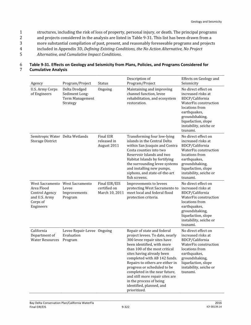
Geology and Seismicity
Bay Delta Conservation Plan/California WaterFix Final EIR/EIS
Administrative Final 9-322
2016 ICF 00139.14
structures, including the risk of loss of property, personal injury, or death. The principal programs 1 and projects considered in the analysis are listed in Table 9-31. This list has been drawn from a 2 more substantial compilation of past, present, and reasonably foreseeable programs and projects 3 included in Appendix 3D, Defining Existing Conditions, the No Action Alternative, No Project 4 Alternative, and Cumulative Impact Conditions. 5
Table 9-31. Effects on Geology and Seismicity from Plans, Policies, and Programs Considered for 6 Cumulative Analysis 7
Agency Program/Project Status Description of Program/Project
Effects on Geology and Seismicity
U.S. Army Corps of Engineers
Delta Dredged Sediment Long-Term Management Strategy
Ongoing Maintaining and improving channel function, levee rehabilitation, and ecosystem restoration.
No direct effect on increased risks at BDCP/California WaterFix construction locations from earthquakes, groundshaking, liquefaction, slope instability, seiche or tsunami.
Semitropic Water Storage District
Delta Wetlands Final EIR released in August 2011
Transforming four low-lying islands in the Central Delta within San Joaquin and Contra Costa counties into two Reservoir Islands and two Habitat Islands by fortifying the surrounding levee systems and installing new pumps, siphons, and state-of-the-art fish screens.
No direct effect on increased risks at BDCP/California WaterFix construction locations from earthquakes, groundshaking, liquefaction, slope instability, seiche or tsunami.
West Sacramento Area Flood Control Agency and U.S. Army Corps of Engineers
West Sacramento Levee Improvements Program
Final EIR/EIS certified on March 10, 2011
Improvements to levees protecting West Sacramento to meet local and federal flood protection criteria.
No direct effect on increased risks at BDCP/California WaterFix construction locations from earthquakes, groundshaking, liquefaction, slope instability, seiche or tsunami.
California Department of Water Resources
Levee Repair-Levee Evaluation Program
Ongoing Repair of state and federal project levees. To date, nearly 300 levee repair sites have been identified, with more than 100 of the most critical sites having already been completed with AB 142 funds. Repairs to others are either in progress or scheduled to be completed in the near future, and still more repair sites are in the process of being identified, planned, and prioritized.
No direct effect on increased risks at BDCP/California WaterFix construction locations from earthquakes, groundshaking, liquefaction, slope instability, seiche or tsunami.

Geology and Seismicity
Bay Delta Conservation Plan/California WaterFix Final EIR/EIS
Administrative Final 9-323
2016 ICF 00139.14
Agency Program/Project Status Description of Program/Project
Effects on Geology and Seismicity
California Department of Water Resources
Delta Levees Flood Protection Program
Ongoing Levee rehabilitation projects in the Delta.
No direct effect on increased risks at BDCP/California WaterFix construction locations from earthquakes, groundshaking, liquefaction, slope instability, seiche or tsunami.
California Department of Water Resources
Central Valley Flood Management Planning Program
Planning phase Among other management actions, involves levee raising and construction of new levees for flood control purposes.
No direct effect on increased risks at BDCP/California WaterFix construction locations from earthquakes, groundshaking, liquefaction, slope instability, seiche or tsunami.
Sacramento Area Flood Control Agency, Central Valley Flood Protection Board, U.S. Army Corps of Engineers
Flood Management Program
Ongoing South Sacramento Streams Project component consists of levee, floodwall, and channel improvements.
No direct effect on increased risks at BDCP/California WaterFix construction locations from earthquakes, groundshaking, liquefaction, slope instability, seiche or tsunami.
Bureau of Reclamation, California Department of Water Resources
2-Gates Fish Protection Demonstration Project
Delayed Temporary gates would be placed across Old River and Connection Slough in the central Delta and operated from December to March for fish protection purposes.
No direct effect on increased risks at BDCP/California WaterFix construction locations from earthquakes, groundshaking, liquefaction, slope instability, seiche or tsunami.
Bureau of Reclamation, California Department of Water Resources
Franks Tract Project
Delayed State and federal agencies would evaluate and implement, if appropriate and authorized, a strategy to significantly reduce salinity levels in the south Delta and at the CCWD and SWP/CVP export facilities and improve water supply reliability by reconfiguring levees and/or Delta circulation patterns around Franks Tract while accommodating recreational interests
No direct effect on increased risks at BDCP/California WaterFix construction locations from earthquakes, groundshaking, liquefaction, slope instability, seiche or tsunami.

Geology and Seismicity
Bay Delta Conservation Plan/California WaterFix Final EIR/EIS
Administrative Final 9-324
2016 ICF 00139.14
Agency Program/Project Status Description of Program/Project
Effects on Geology and Seismicity
California Department of Water Resources, Bureau of Reclamation, and Contra Costa Water District
Los Vaqueros Expansion Investigation
Final EIR certified by Contra Costa Water Districtin March 2010
The existing Los Vaqueros Reservoir would be expanded up to a total of 275,000 acre-feet to take full advantage of the existing state of the art fish screens currently in use in the Delta. New Delta intakes, pumps, and pipelines would be required to fill the additional reservoir capacity, and water deliveries would be made from the expanded reservoir to Bay Area beneficiaries through new conveyance facilities.
No direct effect on increased risks at BDCP/California WaterFix construction locations from earthquakes, groundshaking, liquefaction, slope instability, seiche or tsunami.
California Department of Water Resources
FloodSAFE California
Ongoing Program
Promotes public safety through integrated flood management while protecting environmental resources; emphasizes action in the Delta. This program is very broad, but is designed to improve flood safety throughout the state while encouraging sound conservation actions that benefit California’s native fish and wildlife and promote wildlife-friendly agricultural practices.
No direct effect on increased risks at BDCP/California WaterFix construction locations from earthquakes, groundshaking, liquefaction, slope instability, seiche or tsunami.
Semitropic Water Storage District
Delta Wetlands Projects
Semitropic Water Storage District issued a Draft EIR in 2010 and a Final EIR in 2012.
Under the current proposal, the project would: 1) provide water to Semitropic WSD to augment its water supply, 2) bank water within the Semitropic Groundwater Storage Bank and Antelope Valley Water Bank, and 3) provide water to other places, including the service areas of the Golden State Water Company and Valley Mutual Water Company.
No direct effect on increased risks at BDCP/California WaterFix construction locations from earthquakes, groundshaking, liquefaction, slope instability, seiche or tsunami.
State and Federal Contractors Water Agency, California Department of Water Resources and MOA Partners
Lower Yolo Restoration Project
The goal of this project is to provide important new sources of food and shelter for a variety of native fish species at the appropriate scale in strategic locations in addition to ensuring continued or enhanced flood protection.
No direct effect on increased risks at BDCP/California WaterFix construction locations from earthquakes, groundshaking, liquefaction, slope instability, seiche or tsunami.
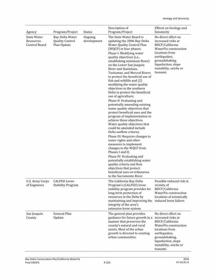
Geology and Seismicity
Bay Delta Conservation Plan/California WaterFix Final EIR/EIS
Administrative Final 9-325
2016 ICF 00139.14
Agency Program/Project Status Description of Program/Project
Effects on Geology and Seismicity
State Water Resources Control Board
Bay-Delta Water Quality Control Plan Update
Ongoing development
The State Water Board is updating the 2006 Bay-Delta Water Quality Control Plan (WQCP) in four phases: Phase I: Modifying water quality objectives (i.e., establishing minimum flows) on the Lower San Joaquin River and Stanislaus, Tuolumne, and Merced Rivers to protect the beneficial use of fish and wildlife and (2) modifying the water quality objectives in the southern Delta to protect the beneficial use of agriculture; Phase II: Evaluating and potentially amending existing water quality objectives that protect beneficial uses and the program of implementation to achieve those objectives. Water quality objectives that could be amended include Delta outflow criteria; Phase III: Requires changes to water rights and other measures to implement changes to the WQCP from Phases I and II; Phase IV: Evaluating and potentially establishing water quality criteria and flow objectives that protect beneficial uses on tributaries to the Sacramento River.
No direct effect on increased risks at BDCP/California WaterFix construction locations from earthquakes, groundshaking, liquefaction, slope instability, seiche or tsunami.
U.S. Army Corps of Engineers
CALFED Levee Stability Program
The California Bay-Delta Program’s (CALFED) levee stability program provides for long-term protection of resources in the Delta by maintaining and improving the integrity of the area’s extensive levee system.
Possible reduced risk in vicinity of BDCP/California WaterFix construction locations of seismically induced levee failure.
San Joaquin County
General Plan Update
The general plan provides guidance for future growth in a manner that preserves the county’s natural and rural assets. Most of the urban growth is directed to existing urban communities.
No direct effect on increased risks at BDCP/California WaterFix construction locations from earthquakes, groundshaking, liquefaction, slope instability, seiche or tsunami.

Geology and Seismicity
Bay Delta Conservation Plan/California WaterFix Final EIR/EIS
Administrative Final 9-326
2016 ICF 00139.14
Agency Program/Project Status Description of Program/Project
Effects on Geology and Seismicity
California State Administration
Sites Reservoir/ North of the Delta Offstream Storage
Determine the viability of a proposed off-stream storage project that could improve water supply, water reliability, support enhanced survival of anadromous fish and other aquatic species
No direct effect on increased risks at BDCP/California WaterFix construction locations from earthquakes, groundshaking, liquefaction, slope instability, seiche or tsunami.
Department of Water Resources
California Water Action Plan
Initiated in January 2014
This plan lays out a roadmap for the next 5 years for actions that would fulfill 10 key themes. In addition, the plan describes certain specific actions and projects that call for improved water management throughout the state.
No direct effect on increased risks at BDCP/California WaterFix construction locations from earthquakes, groundshaking, liquefaction, slope instability, seiche or tsunami.
Delta Conservancy
California EcoRestore
Initiated in 2015
This program will accelerate and implement a suite of Delta restoration actions for up to 30,000 acres of fish and wildlife habitat by 2020.
No direct effect on increased risks at BDCP/California WaterFix construction locations from earthquakes, groundshaking, liquefaction, slope instability, seiche or tsunami.
Department of Water Resources
North Bay Aqueduct Alternative Intake
Notice of Preparation issued on December 2, 2009. CEQA documentation under preparation.
Plan to construct and operate an alternative intake on the Sacramento River, generally upstream of the Sacramento Regional Wastewater Treatment Plant, and connect it to the existing North Bay Aqueduct system by a new pipeline. The proposed alternative intake would be operated in conjunction with the existing North Bay Aqueduct intake at Barker Slough.
No direct effect on increased risks at BDCP/California WaterFix construction locations from earthquakes, groundshaking, liquefaction, slope instability, seiche or tsunami.
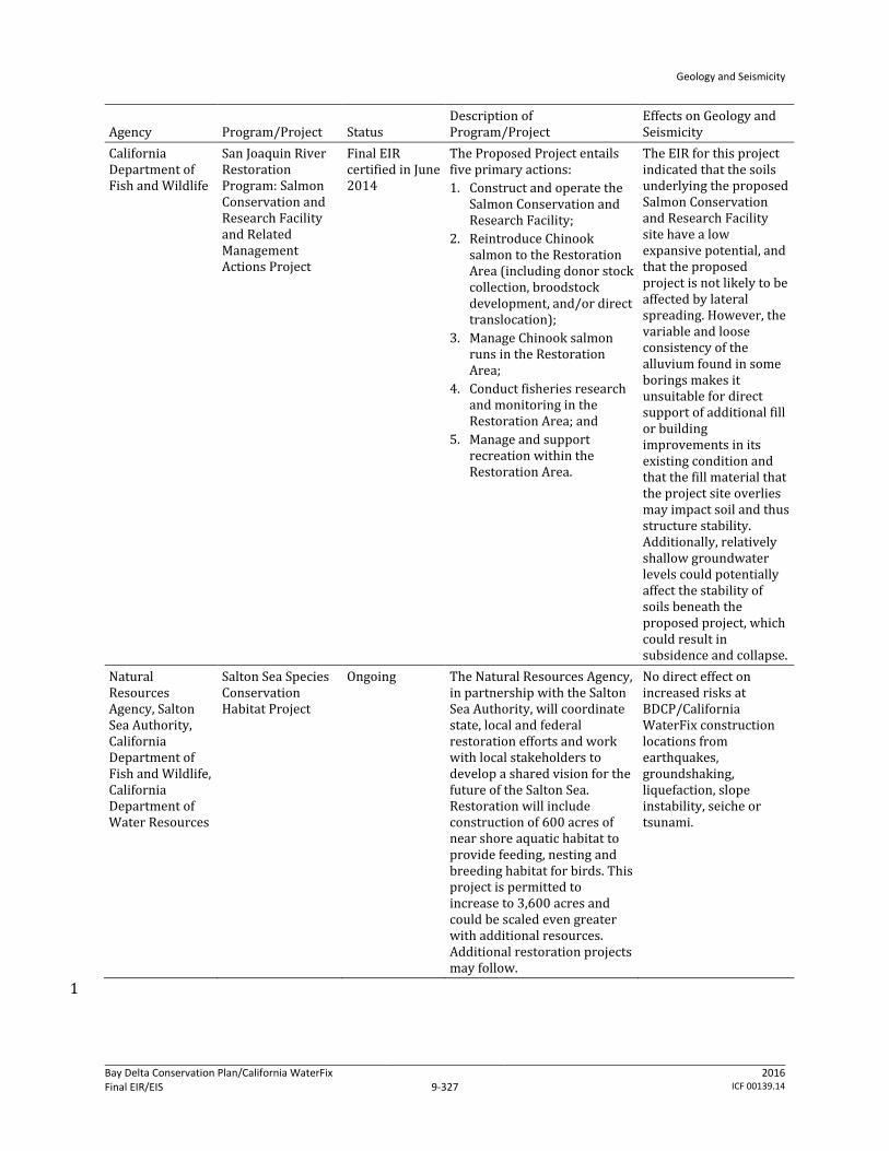
Geology and Seismicity
Bay Delta Conservation Plan/California WaterFix Final EIR/EIS
Administrative Final 9-327
2016 ICF 00139.14
Agency Program/Project Status Description of Program/Project
Effects on Geology and Seismicity
California Department of Fish and Wildlife
San Joaquin River Restoration Program: Salmon Conservation and Research Facility and Related Management Actions Project
Final EIR certified in June 2014
The Proposed Project entails five primary actions: 1. Construct and operate the
Salmon Conservation and Research Facility;
2. Reintroduce Chinook salmon to the Restoration Area (including donor stock collection, broodstock development, and/or direct translocation);
3. Manage Chinook salmon runs in the Restoration Area;
4. Conduct fisheries research and monitoring in the Restoration Area; and
5. Manage and support recreation within the Restoration Area.
The EIR for this project indicated that the soils underlying the proposed Salmon Conservation and Research Facility site have a low expansive potential, and that the proposed project is not likely to be affected by lateral spreading. However, the variable and loose consistency of the alluvium found in some borings makes it unsuitable for direct support of additional fill or building improvements in its existing condition and that the fill material that the project site overlies may impact soil and thus structure stability. Additionally, relatively shallow groundwater levels could potentially affect the stability of soils beneath the proposed project, which could result in subsidence and collapse.
Natural Resources Agency, Salton Sea Authority, California Department of Fish and Wildlife, California Department of Water Resources
Salton Sea Species Conservation Habitat Project
Ongoing The Natural Resources Agency, in partnership with the Salton Sea Authority, will coordinate state, local and federal restoration efforts and work with local stakeholders to develop a shared vision for the future of the Salton Sea. Restoration will include construction of 600 acres of near shore aquatic habitat to provide feeding, nesting and breeding habitat for birds. This project is permitted to increase to 3,600 acres and could be scaled even greater with additional resources. Additional restoration projects may follow.
No direct effect on increased risks at BDCP/California WaterFix construction locations from earthquakes, groundshaking, liquefaction, slope instability, seiche or tsunami.
1
Geology and Seismicity
Bay Delta Conservation Plan/California WaterFix Final EIR/EIS
Administrative Final 9-328
2016 ICF 00139.14
9.3.5.1 Cumulative Effects of the No Action Alternative 1
The cumulative effect of the No Action Alternative is anticipated to result in the current hazard 2 resulting from earthquake-induced ground shaking from regional and local faults persisting. It is 3 also anticipated that the current hazard of earthquake-induced liquefaction triggered by regional 4 and local faults would persist. Slope instability associated with non-engineered levees would 5 continue to present a risk of levee failure and subsequent flooding of Delta islands, with a 6 concomitant influx of seawater into the Delta, thereby adversely affecting water quality and water 7 supply. Ongoing and reasonably foreseeable future projects in parts of the Delta are expected to 8 upgrade the levees to a “flood-safe” condition under the 100-year return flood elevation. However, 9 these projects would provide very little levee foundation strengthening and improvements directed 10 at improving the stability of the levees to better withstand ground shaking, liquefaction, and slope 11 instability. 12
The Delta and vicinity is within a highly active seismic area, with a generally high potential for major 13 future earthquake events along nearby and/or regional faults, and with the probability for such 14 events increasing over time. Based on the location, extent and non-engineered nature of many 15 existing levee structures in the Delta area, the potential for significant damage to, or failure of, these 16 structures during a major local seismic event is generally moderate to high. In the instance of a large 17 seismic event, levees constructed on liquefiable foundations are expected to experience large 18 deformations (in excess of 10 feet) under a moderate to large earthquake in the region. There would 19 potentially be loss, injury or death resulting from ground rupture, ground shaking and liquefaction, 20 (See Appendix 3E, Potential Seismic and Climate Change Risks to SWP/CVP Water Supplies for more 21 detailed discussion). While similar risks would occur under implementation of the action 22 alternatives, these risks may be reduced by project-related levee improvements along with those 23 projects identified for the purposes of flood protection in Table 9-31. 24
9.3.5.2 Concurrent Project Effects 25
Construction of the water conveyance facilities under all action alternatives has the potential to 26 result in the loss of property, personal injury, or death due to structural failure from strong seismic 27 shaking, settlement or collapse caused by dewatering, ground settlement, slope failure, or structural 28 failure due to ground motions. In addition, operation of the water conveyance facilities under all 29 action alternatives could potentially result in the loss of property, personal injury, or death from 30 structural failure resulting from strong seismic shaking or seismic-related ground failure (including 31 liquefaction), landslides and other slope instability, seiche or tsunami, or groundwater surface 32 elevations from unlined canal seepage. These potential effects would be limited to the locations of 33 the construction and the operations activities of the action alternatives. Implementation of the 34 conservation measures in the restoration opportunity areas under Alternatives 1A–2C, 3, 4, 5, and 35 6A–9, could result in similar geologic- and seismic-related risks. 36
The Delta and vicinity is within a highly active seismic area, with a generally high potential for major 37 future earthquake events along nearby and/or regional faults, and with the probability for such 38 events increasing over time. Construction activities for water conveyance facilities and CM2–CM7 39 and CM16 under Alternatives 1A–2C, 3, 4, 5, and 6A–9, could overlap in time, with CM1 construction 40 concluding after approximately 10 years. Similarly, in the long-term, operation of the water 41 conveyance facilities and the habitat areas would occur concurrently. However, there would be little, 42 if any, overlap in location. Therefore, it is unlikely that the potential geologic and seismic hazards 43 resulting from these activities under Alternatives 1A–2C, 3, 4, 5, and 6A–9 would combine to 44
Geology and Seismicity
Bay Delta Conservation Plan/California WaterFix Final EIR/EIS
Administrative Final 9-329
2016 ICF 00139.14
increase the overall risks of loss, injury or death at any one locality in the Plan Area. Environmental 1 commitments to design and manage all active construction sites to meet safety and collapse 2 prevention requirements of the relevant state codes and standards (described in Appendix 3B, 3 Environmental Commitments, AMMs, and CMs) and conformance with Cal-OSHA and other state code 4 requirements such as shoring, bracing, lighting, excavation depth restrictions, required slope angles, 5 and other measures, to protect worker safety would act to reduce the severity of the geologic- and 6 seismic-related hazards. Concurrent geologic and seismicity effects under Alternatives 4A, 2D, and 7 5A would be similar to, but less than, those described under the BDCP alternatives. 8
9.3.5.3 Cumulative Effects of the Action Alternatives 9
Impact GEO-1: Cumulative Impacts Related to Geology and Seismicity Hazards 10
NEPA Effects: Implementation of the action alternatives and other local and regional projects as 11 presented in Table 9-31, could contribute to regional impacts and hazards associated with geology 12 and seismicity. The geologic and seismic hazards that would exist and the potential adverse effects 13 that could occur to structures and persons in association with construction and operation of any 14 action alternative would be restricted to the locations of the construction and the operational 15 activities of these alternatives. Depending on which alternative is chosen, the location of these 16 impacts would vary slightly. These impacts include the potential for loss, injury or death as a result 17 of strong seismic shaking, settlement or collapse caused by dewatering, ground settlement, slope 18 failure (including decreased levee stability from construction and operation activities), seismic-19 related ground failure (including liquefaction), ground shaking, fault rupture, seiche or tsunami. All 20 of the impacts are mitigated by incorporating standard construction and structural measures into 21 project design and construction. No impacts related to construction or operation of any of the action 22 alternatives or from implementation of the conservation measures were identified for this resource 23 area. These cumulative impacts would result from construction activities and development of 24 additional structures that may be subject to geologic, seismic, or slope failure and could be reduced 25 by implementing measures similar to those described for proposed project. However, these projects 26 would not increase the risks to structures and people at the specific locations affected by the action 27 alternatives. Therefore, the risks of loss of property, personal injury, or death associated with the 28 alternatives would not combine with the geologic and seismic risks from other projects or programs 29 to create a cumulatively adverse effect at any one locality in the Plan Area. There would be no 30 cumulative adverse effect. 31
CEQA Conclusion: The geologic and seismic hazards that would exist and the potential adverse 32 effects that could occur in association with construction and operation of any action alternative 33 would be restricted to the locations of the construction and the operational activities of these 34 alternatives. Other past, present and probable future projects and programs in the Plan Area that 35 are identified in Table 9-31 would not increase the risks of loss, injury or death at the specific 36 locations affected by project alternatives. Therefore, the risks of loss, injury or death associated with 37 the project alternatives would not combine with the geologic and seismic risks from other projects 38 or programs to create a substantial cumulative effect at any one locality in the Plan Area. This 39 cumulative impact is considered less than significant. No mitigation is required. 40
Geology and Seismicity
Bay Delta Conservation Plan/California WaterFix Final EIR/EIS
Administrative Final 9-330
2016 ICF 00139.14
9.4 References Cited 1
Atkinson, G. M., and D. M. Boore. 2003. Empirical Ground-Motion Relations for Subduction-Zone 2 Earthquakes and their Application to Cascadia and Other Regions. Bulletin of the Seismological 3 Society of America 93(4):1703–1729. 4
Attewell P. B. and J. P. Woodman. 1982. Predicting the Dynamics of Ground Settlement and its 5 Derivatives Caused by Tunnelling in Soil. Ground Engineering, November 1982: 13-22 6
Atwater, B. F. 1982. Geologic Maps of the Sacramento–San Joaquin Delta, California: U.S. Geological 7 Survey. (Miscellaneous Field Studies Map MF-1401, scale 1:24,000). Reston, VA. 8
Atwater, B. F., and D. F. Belknap. 1980. Tidal–Wetland Deposits of the Sacramento–San Joaquin 9 Delta, California. In: M. E. Field, A. H. Bouma, I. P. Colburn, R. G. Douglas, and J. C. Ingle (eds.). 10 Quaternary Depositional Environments of the Pacific Coast: [papers] Pacific Coast Paleogeography, 11 Symposium 4, April 9, 1980. Los Angeles, CA: Pacific Section, Society of Economic Paleontologists 12 and Mineralogists. 13
Boore, D. M., and G. M. Atkinson. 2007. Boore-Atkinson NGA Ground Motion Relations for the 14 Geometric Mean Horizontal Component of Peak and Spectral Ground Motion Parameters. PEER 15 2007/01, Pacific Earthquake Engineering Research Center Report. 16
British Tunnelling Society. 2005. Closed-Face Tunnelling Machines and Ground Stability: A Guideline 17 for Best Practice. London: Thomas Telford. 18
Brocher, T. M. 2005. A Regional View of Urban Sedimentary Basins in Northern California Based on 19 Oil Industry Compressional-Wave Velocity and Density Logs. Bulletin of the Seismological Society 20 of America 95:2093–2114. 21
Bryant, W. A., and E. W. Hart. 2007. Fault-Rupture Hazard Zones in California Alquist-Priolo 22 Earthquake Fault Zoning Act with Index to Earthquake Fault Zones Maps (Interim Revision). 23 Special Publication 42. California Department of Conservation, California Geological Survey. 24 Sacramento, CA. 25
CALFED Bay-Delta Program. 2000. Levee System Integrity Program Plan, Final Programmatic 26 EIS/EIR Technical Appendix. July. 27
California Department of Conservation. 2000. Seismic Hazard Zone Report 044 for the San Jose East 28 7.5-minute Quadrangle, Santa Clara County, California. Open-File Report 2000-010. Division of 29 Mines and Geology. Available: <http://gmw.consrv.ca.gov/shmp/download/ 30 evalrpt/sjose_eval.pdf>. Accessed: April 25, 2012. 31
———. 2009. Tsunami Inundation Map for Emergency Planning, Benicia Quadrangle. July. 32 Sacramento, CA. Available: <http://www.conservation.ca.gov/cgs/geologic_hazards/Tsunami/ 33 Inundation_Maps/Solano/Documents/Tsunami_Inundation_Benicia_Quad_Solano.pdf>. 34 Accessed: October 21, 2011. 35
California Department of Water Resources. 1992. Seismic Stability Evaluation of the Sacramento–36 San Joaquin Delta Levees, Volume 1, Phase I Report: Preliminary Evaluations and Review of 37 Previous Studies. August. 38
Geology and Seismicity
Bay Delta Conservation Plan/California WaterFix Final EIR/EIS
Administrative Final 9-331
2016 ICF 00139.14
———. 2007a. Technical Memorandum: Delta Risk Management Strategy (DRMS) Phase 1 (Topical 1 Area: Seismology, Final). Prepared by URS Corporation/Jack R. Benjamin and Associates, Inc. 2
———. 2007b. Draft Summary Report: Delta Risk Management Strategy (DRMS) Phase 1 (Risk 3 Analysis, Draft). Prepared by URS Corporation/Jack R. Benjamin and Associates, Inc. 4
———. 2008a. Technical Memorandum: Delta Risk Management Strategy (DRMS) Phase 1: Topical 5 Area: Levee Vulnerability (Final). May. Prepared by URS Corporation/Jack R. Benjamin and 6 Associates, Inc. 7
———. 2008b. Risk Analysis Report (Final): Delta Risk Management Strategy (DRMS) Phase 1. 8 December. Prepared by URS Corporation/Jack R. Benjamin and Associates, Inc. 9
———. 2009a. Conceptual Engineering Report—Isolated Conveyance Facility—East Option. 10 November 18. Revision 1. Delta Habitat Conservation and Conveyance Program. Sacramento, CA. 11
———. 2009b. Conceptual Engineering Report—Isolated Conveyance Facility—West Option. 12 November 25. Revision 0. Delta Habitat Conservation and Conveyance Program. Sacramento, CA. 13
———. 2010a. Conceptual Engineering Report—Isolated Conveyance Facility—All Tunnel Option. 14 March 10. Revision 0. Design Document 500-05-05-100-03. Delta Habitat Conservation and 15 Conveyance Program. Sacramento, CA. 16
———. 2010b. Conceptual Engineering Report—Isolated Conveyance Facility—Pipeline/Tunnel 17 Option (formerly All Tunnel Option)—Addendum. October 22. Delta Habitat Conservation and 18 Conveyance Program. Sacramento, CA. 19
———. 2010c. Conceptual Engineering Report—Isolated Conveyance Facility—East Option—20 Addendum. October 25. Delta Habitat Conservation and Conveyance Program. Sacramento, CA. 21
———. 2010d. Conceptual Engineering Report—Isolated Conveyance Facility—West Option—22 Addendum. October 25. Delta Habitat Conservation and Conveyance Program. Sacramento, CA. 23
———. 2010e. Option Description Report—Separate Corridors Option, Volume 1—Report. June. 24 Revision 0. Document 600-05-05-100-001. Delta Habitat Conservation and Conveyance 25 Program. Sacramento, CA. 26
———. 2010f. The State Water Project Delivery Reliability Report 2009. August. Available: 27 <http://baydeltaoffice.water.ca.gov/swpreliability/Reliability2010final101210.pdf>. Accessed: 28 September 6, 2010. 29
———. 2010g. Draft Phase I Geotechnical Investigation—Geotechnical Data Report—Isolated 30 Conveyance Facility West. July 12. Revision 0. Document 002-31-05-183-001. Delta Habitat 31 Conservation and Conveyance Program. Sacramento, CA. 32
———. 2010h. Draft Phase I Geotechnical Investigation—Geotechnical Data Report—Isolated 33 Conveyance Facility East. July 12. Revision 0. Delta Habitat Conservation and Conveyance 34 Program. Sacramento, CA. 35
———. 2010i. Draft Report of the Analysis and Optimization of the Pipeline/Tunnel Option. November 36 23. Document 005-05-05-100-004. Delta Habitat Conservation and Conveyance Program. 37 Sacramento, CA. 38
Geology and Seismicity
Bay Delta Conservation Plan/California WaterFix Final EIR/EIS
Administrative Final 9-332
2016 ICF 00139.14
———. 2011. Draft Phase II Geotechnical Investigation—Geotechnical Data Report—Pipeline/Tunnel 1 Option. August 22. Revision 1.1. Delta Habitat Conservation and Conveyance Program. 2 Sacramento, CA. 3
———. 2014. Draft Geotechnical Exploration Plan—Phase 2. October 14. Revision 5. Delta Habitat 4 Conservation and Conveyance Program. Sacramento, CA. 5
———. 2015. Conceptual Engineering Report — Dual Conveyance Facility Modified Pipeline/Tunnel 6 Option—Clifton Court Forebay Pumping Plant (MPTO/CCO). Volume 1. April 1. Delta Habitat 7 Conservation and Conveyance Program. Sacramento, CA. 8
California Department of Water Resources and California Department of Fish and Game. 2008. Risk 9 and Options to Reduce Risks to Fishery and Water Supply Uses of the Sacramento/San Joaquin 10 Delta. A Report Pursuant to Requirements of Assembly Bill 1200, Laird. 11
California Division of Oil and Gas. 1982. Oil and Gas Fields, Northern California: Volume 3 of 12 Publication TR10. State of California. 13
California Geological Survey. 2008. Guidelines for Evaluating and Mitigating Seismic Hazards in 14 California. Special Publication 117A. Sacramento, CA. 15
Campbell, K. W., and Y. Bozorgnia. 2007. Campbell-Bozorgnia NGA Ground Motion Relations for the 16 Geometric Mean Horizontal Component of Peak and Spectral Ground Motion Parameters. PEER 17 2007/02. Pacific Earthquake Engineering Research Center. 18
Cao, T., W. A. Bryant, B. Rowshandel, D. Branum, and C. J. Wills. 2003. Revised 2002 California 19 Probabilistic Seismic Hazard Maps, June. California Geological Survey. 20
Chapman, D. N. C. D. F. Rogers, and D. V. L. Hunt. 2004. Predicting the Settlements above Twin Tunnels 21 Constructed in Soft Ground. School of Engineering, Civil Engineering, The University of 22 Birmingham, U.K. 23
Cherven, V. B., and S. A. Graham (eds.). 1983. Geology and Sedimentology of the Southwestern 24 Sacramento Basin and East Bay Hills. Field Trip Guidebook, Pacific Section (Society of Economic 25 Paleontologists and Mineralogists). Los Angeles, CA: Pacific Section, Society of Economic 26 Paleontologists and Mineralogists. 27
Chiou, B. S-J., and R. R. Youngs. 2006. Chiou and Youngs PEER NGA Empirical Ground Motion Model 28 for the Average Horizontal Component of Peak Acceleration and Pseudo-Spectral Acceleration 29 for Spectral Periods of 0.01 to 10 Seconds. Interim Report for U.S. Geological Survey Review. 30 Revised July 10, 2006. 31
City and County of San Francisco. 2011. Emergency Response Plan—Tsunami Response Annex. March. 32 An element of the CCSF Emergency Management Program. San Francisco, CA. 33
Contra Costa County. 2009. Draft Environmental Impact Report, Contra Costa Pipeline Project. May. 34 State Clearinghouse No. 20070662007. Department of Conservation and Development. 35
Contra Costa Transportation Agency. 2009. Draft Environmental Impact Report, 2009 Countywide 36 Comprehensive Transportation Plan. February 18. State Clearinghouse No. 2008052073. 37

Geology and Seismicity
Bay Delta Conservation Plan/California WaterFix Final EIR/EIS
Administrative Final 9-333
2016 ICF 00139.14
County of Sacramento. 1993. Safety Element: Background to the 1993 General Plan as Amended. 1 Planning and Community Development Department. Sacramento, CA. Available: 2 < http://www.per.saccounty.net/PlansandProjectsIn-Progress/Documents/ 3 General%20Plan%202030/Safety%20Element%20Background.pdf >. Accessed: June 21, 2013. 4
Dean A., D. J. Young, and G. J. E. Kramer. 2006. The Use and Performance of Precast Concrete Tunnel 5 Linings in Seismic Areas. September. International Association of Engineering Geology (IAEG) 6 Congress. 7
DeCourten, F. 2008. Geology of Northern California. Available: <http://cengage.com/custom/ 8 regional_geology/data/DeCourten_0495763829_LowRes_New.pdf>. Accessed: September 21, 9 2012. 10
Fugro Consultants. 2011. Reprocessing and Interpretation of Seismic Reflection Data, Clifton Court 11 Forebay. Letter to Mark Pagenkopp, California Department of Water Resources. July 22. Walnut 12 Creek, CA. 13
Graymer, R. W., D. L. Jones, and E. E. Brabb. 2002. Geologic Map and Map Database of Northeastern 14 San Francisco Bay Region, California, Most of Solano Country, and Parts of Napa, Marin, Contra 15 Costa, San Joaquin, Sacramento, Yolo, and Sonoma Counties. U.S. Geological Survey 16 Miscellaneous Field Studies Map MF-2403. U.S. Geological Survey. Menlo Park, CA. 17
Hansen, D. T., G. J. West, P. Welch, and B. Simpson. 2001. Geomorphology_Delta. U.S. Bureau of 18 Reclamation, Mid-Pacific Region GIS. Available: <http://atlas.ca.gov/catalog/>. Accessed: April 19 9. 2012. 20
Helley, E. J., and J. A. Barker. 1979. Preliminary Geologic Map of Cenozoic Deposits of the Guinda, 21 Dunningan, Woodland, and Lake Berryessa Quadrangles, California. U.S. Geological Survey Open-22 File Report OF-79-1606, 4 sheets, scale 1:62,500. Available: 23 <http://ngmdb.usgs.gov/Prodesc/proddesc_11190.htm>. Accessed: April 25, 2012. 24
Hendy, I. L., and J. P. Kennett. 2000. Stable Isotope Stratigraphy and Paleoceanography of the Last 25 170 K. Y.: ODP Site 1014, Tanner Basin, California. In: M. Lyle, I. Koizumi, C. Richter, and T. C. 26 Moore, Jr. (eds.). Proceedings of the Ocean Drilling Program, Scientific Results 167:129–140. 27 College Station, TX. 28
Imbrie, J., J. D. Hays, D. G. Martinson, A. McIntyre, A. C. Mix, J. J. Morley, N. G. Pisias, W. L. Prell, and 29 N. J. Shackleton. 1984. The Orbital Theory of Pleistocene Climate: Support from a Revised 30 Chronology of the Marine δ18O Record. In Berger et al. (eds.). Milankovitch and Climate (Part 1): 31 NATO ASI Series C, Math and Physical Science 126:269–305. 32
International Tunneling Association. 2007. Report on Settlements Induced by Tunneling in Soft 33 Ground. Tunnelling and Underground Space Technology 2:119–149. 34
Lettis, W. R., and J. R. Unruh. 1991. Quaternary Geology of the Great Valley, California. In 35 R. B. Morrison (ed.), Quaternary Non-Glacial Geology of the Western United States: Decade of 36 North American Geology. Volume K-2, Geological Society of America. Pages 164–176. 37
Geology and Seismicity
Bay Delta Conservation Plan/California WaterFix Final EIR/EIS
Administrative Final 9-334
2016 ICF 00139.14
Marchand, D. E. 1977. The Cenozoic History of the San Joaquin Valley and the Adjacent Sierra 1 Nevada as Inferred from the Geology and Soils of the Eastern San Joaquin Valley. In Singer, M. J. 2 (ed.), Soil Development, Geomorphology, and Cenozoic History of the Northeastern San Joaquin 3 Valley and Adjacent Areas, California. Guidebook for Joint Field Session, Soil Science Society of 4 America and Geologic Society of America. University of California Press. 5
Martinson, D. G., N. G. Pisias, J. D. Hays, J. Imbrie, T. C. Moore, and N. J. Shackleton. 1987. Age Dating 6 and the Orbital Theory of the Ice Ages—Development of a High-Resolution-0 to 300,000-Year 7 Chronostratigraphy. Quaternary Research 27(1): 1–29. 8
Miller, A. W., R. S. Miller, H. C. Cohen, and R. F. Schultze. 1975. Suisun Marsh Study, Solano County, 9 California. U.S. Department of Agriculture Soil Conservation Service. 10
Norris, R. M., and R. W. Webb. 1990. Geology of California. Second Edition. New York: John Wiley & 11 Sons, Inc. 12
National Research Council. 2004. Adaptive Management for Water Resources Project Planning. 13 Washington, DC: National Academies Press. 14
National Research Council of Canada. 1983. A Method of Estimating Surface Settlement above Tunnels 15 Constructed in Soft Ground. 16
Petersen, M. D., A. D. Frankel, S. C. Harmsen, C. S. Mueller, K. M. Haller, R. L. Wheeler, R. L. Wesson, 17 Y. Zeng, O. S. Boyd, D. M. Perkins, N. Luco, E. H. Field, C. J. Wills, and K. S. Rukstales. 2008. 18 Documentation for the 2008 Update of the United States National Seismic Hazard Maps. U.S. 19 Geological Survey Open-File Report 2008-1128. 20
Real, C. R., and K. L. Knudsen. 2009. Application of New Liquefaction Hazard Mapping Technique to 21 the Sacramento-San Joaquin Delta Area. Final Technical Report. December 23. Collaborative 22 Research with URS Corporation, California Geological Survey. 23
Roberts, S., M. Roberts, and E. Brennan. 1999. Landslides in Alameda County, California. A digital 24 database extracted from preliminary photointerpretation maps of surficial deposits by T. H. 25 Nilsen. In: U.S. Geological Survey Open File Report 75-277. Open-File Report 99-504. U.S. 26 Geological Survey. 27
San Joaquin County. 1992. Countywide General Plan 2010. Volume I, Chapter V. Public Health and 28 Safety. Amended 2005, 2010. Community Development Department, Stockton, CA. Available: 29 <http://www.sjgov.org/commdev/cgi-bin/cdyn.exe?grp=planning&htm=generalplan>. 30 Accessed: June 21, 2013. 31
Shlemon, R. J. 1971. The Quaternary Deltaic and Channel System in the Central Great Valley, 32 California. Annals of the Association of American Geographers 61:427–440. 33
Shlemon, R. J., and E. L. Begg. 1975. Late Quaternary Evolution of the Sacramento–San Joaquin Delta, 34 California. In R. P. Suggate and M. M. Cresswell (eds.), Quaternary Studies 13:259–266. 35 Wellington, New Zealand: The Royal Society of New Zealand. 36
Solano County. 2008. Solano County General Plan. December. Fairfield, CA. Available: 37 <http://www.co.solano.ca.us/depts/rm/planning/general_plan.asp>. Accessed: February 11, 38 12, and 13, 2009; January 17, 2012. 39
Geology and Seismicity
Bay Delta Conservation Plan/California WaterFix Final EIR/EIS
Administrative Final 9-335
2016 ICF 00139.14
Tolmachoff, W. 1993. Linear Velocity Functions and the Effect of Mentors in the Oil Industry. 1 Association of Petroleum Geologists Pacific Section. Newsletter No. 2, Pacific Section, American 2 Association of Petroleum Geologists. Pages 4–5. 3
Torres, R. A., N. A. Abrahamson, F. N. Brovold, G. Cosino, M. W. Driller, L. F. Harder, N. D. Marachi, C. 4 N. Neudeck, L. M. O’Leary, M. Ramsbotham, and R. B. Seed. 2000. Seismic Vulnerability of the 5 Sacramento-San Joaquin Delta Levees. CALFED Bay-Delta Program, Levees and Channels 6 Technical Team, Seismic Vulnerability Sub-Team. April. 7
U.S. Department of Transportation, Federal Highway Administration. 2009. Technical Design Manual 8 for Design and Construction of Road Tunnels. 9
U.S. Geological Survey. 2008. United States National Seismic Hazard Maps. 2008 Hazard Maps – 10 Revision III. Available: 11 <http://earthquake.usgs.gov/hazards/hazmaps/conterminous/2008/maps-rev3.php>. 12
Wagner, D. L. and E. J. Bortugno. 1982. Geologic Map of the Santa Rosa Quadrangle. California 13 Geological Survey, Regional Geologic Map No. 2A, 1:250,000 scale. Last revised: Unknown. 14 Available:<http://www.conservation.ca.gov/cgs/information/geologic_mapping/Pages/google15 maps.aspx>. Accessed: March 21, 2012. 16
Wagner, D. L., E. J. Bortugno, and R. D. McJunkin. 1991. Geologic Map of the San Francisco—San Jose 17 Quadrangle. California Geological Survey, Regional Geologic Map No. 5A, 1:250,000 scale. Last 18 revised: Unknown. Available:<http://www.conservation.ca.gov/cgs/information/ 19 geologic_mapping/Pages/googlemaps.aspx>. Accessed: March 21, 2012. 20
Wagner, D. L., C. W. Jennings, T. L. Bedrossian, and E. J. Bortugno. 1981. Geologic Map of the 21 Sacramento Quadrangle. California Geological Survey, Regional Geologic Map No. 1A, 1:250,000 22 scale. Last revised: Unknown. Available:<http://www.conservation.ca.gov/ 23 cgs/information/geologic_mapping/Pages/googlemaps.aspx>. Accessed: March 21, 2012. 24
Wells, D. L., and K. J. Coppersmith. 1994. New Empirical Relationships Among Magnitude, Rupture 25 Length, Rupture Width, Rupture Area, and Surface Displacement. Bulletin of the Seismological 26 Society of America 84(4):974–1002. 27
Working Group on California Earthquake Probabilities. 2003. Earthquake Probabilities in the San 28 Francisco Bay Region b: 2002–2031. U.S. Geological Survey Open-File Report 03-214. 29
Working Group on Northern California Earthquake Potential. 1996. Database of Potential Sources for 30 Earthquakes Larger than Magnitude 6 in Northern California. USGS Open-File Report 96-705. 31
Wong, I. and M. Dober. 2007. Screening/Scoping Level Probabilistic Seismic Hazard Analysis for 32 Buckhorn Dam, California. Unpublished Report. Prepared for Bureau of Reclamation. Prepared 33 by URS Corporation. 34
Youd, T. L. and S. N. Hoose. 1978. Historic Ground Failures in Northern California Triggered by 35 Earthquakes. U.S. Geological Survey Professional Paper 993. U.S. Government Printing Office. 36 Washington, DC. 37
Youngs, R. R., S-J. Chiou, W. A. Silva, and J. R. Humphrey. 1997. Strong Ground Motion Attenuation 38 Relationships for Subduction Zone Earthquakes. Seismological Society of America. Seismological 39 Research Letters 68:58–73. 40