Embed Size (px)
Citation preview

The study on sewerage system development in the Syrian Arab Republic Final Report
M9-1
CHAPTER 9 ESTABLISHMENT OF THE SEWERAGE DEVELOPMENT MASTER PLAN
9.1 Basic Condition for Master Plan
9.1.1 Target Year
One of Japan’s most highly authoritative design guideline entitled, “Design Guidelines for Sewerage System” prescribes that the target year for a sewerage development plan shall be set approximately 20 years later than the current year. This is due to the following reasons: • The useful life of both the facilities and the construction period should extend over a long
period of time; • Of special significance to sewer pipe construction is the phasing of the capacity
strengthening. This should be based on the sewage volume increase although this may be quite difficult to track;
• Therefore, the sewerage facility plan shall be based on long-term prospect, such as the long-term urbanization plan.
In as much as this study started in November 2006, the year 2006 can be regarded as the “present” year. Though 20 years after 2006 is 2026, this was correspondingly adjusted as 2025. Hence, the year 2025 was adopted as target year for this Study. 9.1.2 Sanitation System / Facilities
The abovementioned guideline describes “service area” as the area to be served by the sewerage system, as follows: • Since the service area provides the fundamental condition for the sewerage system
development plan, investment-wise, the economic and O&M aspects shall be dully examined upon the delineation of the area.
• The optimum area, the area where the target pollution reduction can be achieved as stipulated in theover-all development plan, shall be selected carefully.
• Basically, the service area is the area of advantage that will be served by the centralized sewerage system based on the level of urbanization and the conditions obtaining in the surrounding communities in the target year.
The development of the sewerage system in Syria has just started and by and large, only the development of the sewer network has proceeded without the benefit of the over-all development plan. This resulted in the pollution of public water bodies that have been receiving the discharged raw sewage.
The study on sewerage system development in the Syrian Arab Republic Final Report
M9-2
As mentioned earlier, the service area is the area of advantage to be served by the centralized sewerage system. Its condition corresponds to those conditions obtaining in urbanized areas where large populations reside in densely constructed housing settlements. Options are available to integrate the treatment of sewage generated by communities located near the urban area, and send these to the existing pipe network of the urban area through connecting sewer pipes. It will thus form part of the integrated sewage treatment by STP in the subject urban area. However, this option is only applicable if it is deemed advantageous by economical standards. The prerequisite is the existence of a huge number of communities that are unserved. Sewage generated in these communities shall be properly treated as well. On-site system development is applicable in these cases. The on-site system can be divided into two methods, namely 1) Pit Latrine and 2) Septic Tank. The Pit Latrine is a bare ground pit dug into the ground. As most of them are not concrete-lined, there is risk of groundwater contamination is high if the ground has a high permeability. The typical on-site system prevalent in Syria is the Pit Latrine but as stated, but since it bears the potential risk of groundwater contamination, the method shall be converted into the Septic Tank method with less effluent pollution load. Generally, the Septic Tank is comprised of two adjoining compartments made of concrete. Solids settle at the bottom of each compartment and are digested in anaerobic condition and the scum layer takes form on the surface. Solid sediments will decrease volumetrically but as part of the solids will be accumulated, the periodic removal of sludge should be undertaken at least once every five years, is necessary. Since the effluent collected cannot be discharged without any treatment, it shall be discharged into the soak pit or soak ditch. Absorption by plants will be effective as well. 9.1.3 Sewage Collection System
The guideline forwards that the “Sewage collection method shall be a separate system, in general. However, if the appropriate countermeasures are taken for the purpose of coping with conditions in the receiving water body, the combined system can be adopted.” The comparison between the Combined System and Separate System is shown in Table 9.1.1:

The study on sewerage system development in the Syrian Arab Republic Final Report
M9-3
Table 9.1.1 Comparison of Combined System and Separate System
Items Combined Sewerage System Separate Sewerage System Workability As sewage and storm water is collected by
means of one sewer, construction work is easy, posing no hindrance to other underground construction. The pipe diameter is larger that those of separate system.
As sewage and storm water is collected by two sewers respectively, construction work will be difficult in narrow streets. Since the diameter of the sewage pipe is small and its slope is large, pipe installation depth may become large in turn.
Con
stru
ctio
n W
ork
Cost Cheap, as sewage and storm water is collected by one sewer.
If the sewer for both sewage and storm water is constructed, the cost will be expensive. If only the sewer is constructed, the cost will be less.
O&
M
In-pipe sediments
As the diameter is large and the in-pipe velocity is small, settlement is apt to occur. Sediments will be flushed by storm water.
As to the sewer pipe, its volume is comparatively small. As to the storm water drainage pipe, settlement is apt to occur as in the case of the Combined System. Sediments will be flushed by storm water.
Soil, sand intrusion
Intrusions mainly originate from road surfaces. This causes the defacement of the machinery and sand sedimentation.
Less in sewer pipe. In case of storm water drainage pipe, some soil and sand intrusion is observed.
Inspection, Cleaning
As the diameter is large, inspection is made easier but in the case of super large diameters, cleaning may be difficult.
As to the sewer pipe, clogging may occur due to its small diameter but cleaning is easy. As to the storm water drainage pipe, the same conditions prevail as in the Combined System.
Ope
ratio
n an
d M
aint
enan
ce
Mis- connection of storm drainage facilities
None Shall be duly guided. This might cause inundation during rains.
Combined Sewer Overflow
As pollutant overflows into the water bodies, there is a high risk of water pollution and environmental degradation. Proper countermeasure for combined sewer overflow is needed.
None
Wat
er Q
ualit
y Pr
eser
vatio
n
Pollution load of Non-point Source
Collection and treatment of initial turbid storm water is possible. Incoming volume exceeding the capacity of the interceptor pipe will be discharged into water bodies without any treatment.
Storm water is discharged into water bodies without any treatment.
Land Use Since the existing drainage gutter will be abolished, the resultant road widening and use will be beneficial
Storm water drainage gutter may remain.
The guideline indicates the adoption of a Separate Sewerage System in principle, considering the combined overflow of sewer into public water bodies and the load increase in the STP. In Syria, the Combined Sewerage System has been adopted and has been implemented in many cities, towns and villages. The annual rainfall in Syria varies by Governorates and ranges widely from as high as 800 mm/year at the Mediterranean Coastal Area to as low as 200 mm/year at the Rural Damascus Governorate. Except for the Mediterranean Coastal Area, the annual rainfall is not heavy enough to require planning for a storm water overflow chamber to mitigate the wet weather sewage volume flowing into the STP, as this seems much less. Meanwhile, the storm water overflow chamber shall be planned because the projected storm water volume may not be negligible owing to the heavy annual rainfall. As mentioned above,
The study on sewerage system development in the Syrian Arab Republic Final Report
M9-4
the proper countermeasure for the combined sewer overflow should be definitely taken to reduce the discharge of the pollution load into the public water bodies. Furthermore, the replacement of deteriorated pipe network is preferably desirable. 9.1.4 Summary of Design Sewage Flow and Design Sewage Quality
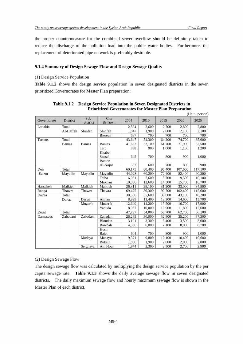
(1) Design Service Population Table 9.1.2 shows the design service population in seven designated districts in the seven prioritized Governorates for Master Plan preparation:
Table 9.1.2 Design Service Population in Seven Designated Districts in Prioritized Governorates for Master Plan Preparation
(Unit : person)
Governorate District Sub -district
City & Town 2004 2010 2015 2020 2025
Lattakia Total 2,534 2,600 2,700 2,800 2,800 Al-Haffeh Slunfeh Slunfeh 1,847 1,900 2,000 2,100 2,100 Biereen 687 700 700 700 700Tartous Total 43,647 54,300 64,200 74,700 85,600 Banias Banias Banias 41,632 52,100 61,700 71,900 82,500 Tero 838 900 1,000 1,100 1,200
Khabet Snasel 645 700 800 900 1,000
Boston Al-Najor 532 600 700 800 900
Deir Total 60,175 80,400 95,400 107,600 117,100-Ez zor Mayadin Mayadin Mayadin 44,028 60,200 72,400 82,400 90,300 Taiba 6,061 7,600 8,700 9,500 10,100 Makhan 10,086 12,600 14,300 15,700 16,700Hassakeh Malkieh Malkieh Malkieh 26,311 29,100 31,200 33,000 34,500Raqqa Thawra Thawra Thawra 69,425 80,300 90,700 102,400 115,600Dar'aa Total 30,536 35,600 39,600 43,100 46,200 Dar'aa Atman 8,929 11,400 13,200 14,600 15,700 Muzerib Muzerib 12,640 14,200 15,500 16,700 17,900
Dar'aa Yaduda 8,967 10,000 10,900 11,800 12,600
Rural Total 47,737 54,000 58,700 62,700 66,100Damascus Zabadani Zabadani Zabadani 26,285 30,000 32,800 35,200 37,300 Bloudan 3,101 3,300 3,400 3,500 3,600 Rawdah 4,536 6,000 7,100 8,000 8,700
Hosh Bajet 604 700 800 900 1,000
Madaya Madaya 9,371 9,800 10,100 10,400 10,600 Bukein 1,866 1,900 2,000 2,000 2,000 Serghaya Ain Hour 1,974 2,300 2,500 2,700 2,900
(2) Design Sewage Flow The design sewage flow was calculated by multiplying the design service population by the per capita sewage rate. Table 9.1.3 shows the daily average sewage flow in seven designated districts. The daily maximum sewage flow and hourly maximum sewage flow is shown in the Master Plan of each district.

The study on sewerage system development in the Syrian Arab Republic Final Report
M9-5
Table 9.1.3 Daily Average Sewage Flow in Seven Designated Districts (Unit : m3/day)
Governorates District Sub -district
City & Town 2004 2010 2015 2020 2025
Total Lattakia Total 1,383 1,489 1,620 1,757 1,833 Al-Haffa Slunfeh Slunfeh 1,008 1,088 1,200 1,318 1,375 Biereen 375 401 420 439 458Tartous Total 8,273 10,834 13,429 16,346 19,556 Banias Banias Banias 8,053 10,582 13,129 15,995 19,151
Tero, Snasel,Najor 220 252 300 351 406
Deir-Ez-zor Total 7,440 10,466 13,031 15,383 17,483 Mayadeen Mayadeen Mayadeen 5,678 8,152 10,270 12,220 13,974 Taiba 661 871 1,044 1,192 1,323 Makhan 1,101 1,444 1,716 1,970 2,187Hassakeh Malkieh Malkieh Malkieh 2,871 3,334 3,745 4,141 4,518Raqqa Thawra Thawra Thawra 8,953 10,873 12,866 15,186 17,889Dar'aa Total 3,332 4,079 4,753 5,409 6,050 Dar'aa Atman 974 1,306 1,584 1,832 2,056
Dar'aa Muzerib Muzerib 1,379 1,627 1,860 2,096 2,344
Yaduda 978 1,146 1,308 1,481 1,650Rural Total 14,546 17,176 19,498 21,709 23,851Damascus Zabadani Zabadani Zabadani 10,169 12,187 13,959 15,661 17,317 Bloudan 1,354 1,512 1,632 1,757 1,886 Rawdah 495 687 852 1,004 1,139 Hosh Bajet 66 80 96 113 131 Madaya Madaya 1,534 1,684 1,818 1,958 2,082 Bukein 713 762 840 878 917 Surghya Ain Hour 215 264 300 339 380
(3) Design Sewage Quality As described in the previous section, (7.4.2 Wastewater Quality), the design sewage quality of domestic sewage was established based on the pollution load and verified by the existing data and results of the sewage quality survey conducted in the course of the Study. Refer to Table 9.1.4.
Table 9.1.4 Design Sewage Quality
Water Quality Indices
Design Sewage Quality (mg/l)
BOD 310 SS 360 T-N 74 T-P 24
9.1.5 Sewage Treatment Method
9.1.5.1 External Conditions for Sewage Treatment Method (1) Incoming Sewage Quality Incoming Sewage Quality is one of the most important external conditions. As described in previous sections (7.4.2 2) Design Sewage Quality), a BOD concentration of 310 mg/l is approximately 1.5 times the standard Japanese sewage quality. Therefore, the tank capacity and oxygen requirement will become 1.5 times the Japanese examples.

The study on sewerage system development in the Syrian Arab Republic Final Report
M9-6
(2) Sewerage Flow for STP Design Japanese design standard has description that STP facilities shall be designed based on daily maximum sewage flow. In this study, daily maximum flow and hourly maximum flow was established based on daily average flow. However, as sewage flow estimated in this study has many indefinite factors and it is quite different from sewage flow estimated based on numerous existing data, it shall be examined whether STP facility design based on daily maximum flow is feasible in Syria. Accounting the following items into consideration, STP facility design by daily average flow was judged as appropriate to avoid excessive design and to realize effective and economical facility design: • As tourism sewage flow was estimated without any actual flow measurement or any
existing ground-data, STP facility design shall be carefully conducted to avoid excessive design.
• Water consumption rate is quite limited due to water source restriction. Generally precipitation is also small depends on areas and therefore, annual incoming sewage flow fluctuation is relatively small compared to Japan.
• By adoption of low-loaded system such as OD method, stable treatment against fluctuation in incoming sewage rate is ensured. In this study, 40 hours of retention time was secured owing to the high concentration of design sewage quality and to the restriction of BOD-SS loading.
STP facility design by other donor agencies also adopted daily average sewage flow (3) Effluent Standards Effluent standards for treated sewage shall be established depending on the status of the receiving water bodies and the usage of the treated effluents. The conditions of setting effluence standard vary in the different Governorates, for example; • As the contamination of groundwater is in an advanced state in Rural Damascus, the
effluent standard in Zabadani shall be set up to enable the re-use of treated sewage for irrigating vegetable farms. However, if treated sewage is to be discharged into the river, the standard of SS 30 mg/l shall be applied. This level is more stringent than the 50 mg/l applied for treated wastewater to be used for irrigating vegetable farms.
• In Muzerib, groundwater is abundant and commonly used for irrigation. Therefore, the treated sewage is discharged into the river and the corresponding stringent effluent standard should be considered.
• In Slunfeh, Thawra and Mayadin, treated sewage is discharged into the river as well. • In Malkieh, the treated sewage is applied to the irrigation of cotton and industrial crops.
The effluent standard for the irrigation of industrial crops is BOD 150 mg/l which is slacker than the 30mg/l for discharge to river. Therefore, the effluent standard for the discharge of effluents into the river shall be applied.
Refer to Table 9.1.5:

The study on sewerage system development in the Syrian Arab Republic Final Report
M9-7
Table 9.1.5 Example of Effluent Standard (Unit : mg/l) M/P Area Maximum Allowed Limited effluent standard from STP
Discharge mode to water-body
/ Condition of re-use BOD SS NH3-N NO3-N Zabadani Irrigation (vegetable)/river Muzerib River
3040
3030
3 5
2050
Slunfeh River 40 30 5 50Banias Sea 60 60 10 50Thawra River 40 30 5 50Mayadin Malkieh
River River /Irrigation (Industrial crops)
4040
3030
5 5
5050
(4) Treatment Method related to Duty Time Mainly, life in Syria centers on the family, and working time falls between 8:00 a.m. to 15:30 p.m. Most of the STP operators return home in the evening, which is also the peak time of incoming sewage flow. In the Adraa STP, some engineers continue working at the STP in the evening for the purpose of doing equipment repair as required. In evaluating the treatment performance, composite samples are collected every three hours by workers and handed over to the laboratory in the morning for analysis. Although the engineers evaluate the average treated sewage quality on a daily basis, they cannot evaluate the detailed treatment performance during peak hours under the current lifestyle practices. The labor environment is thus traditionally oriented toward attaining the desirable family centered life. To maintain this labor environment and to achieve operational responsibility during peak flow time, the adoption of treatment processes requiring simple and lesser units of equipment and processes with long retention time is preferable. In Japan, the Oxidation Ditch Method with long retention time and a simplified treatment process is widely applied. Routine O&M is executed during daytime and the plant is operated without operators at night. (5) Issues on Manpower Securing and Remarks on Sewage Treatment Method Selection Currently, the number of plant operators is quite insufficient in Syria. Therefore, the human resources management should be strengthened in the following manner to ensure the presence of O&M engineers for new STP: • Generate surplus engineers by re-structuring the O&M staffing at existing STPs • Introduction of simplified sewage treatment methods
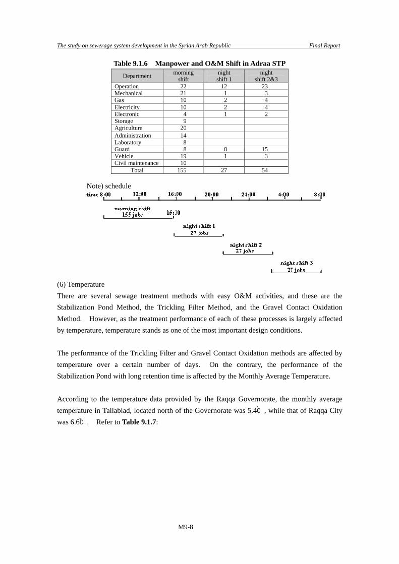
At the Adraa STP, more than 200 O&M staff members are working everyday and repair works are executed even during nighttime. Therefore, it seems possible to transfer some engineers to other STPs by improving the working efficiency of O&M activities. Refer to Table 9.1.6: Since O&M cost, especially labor costs, contribute a large percentage to the total project cost, the use of simplified sewage treatment processes, when adopted, could reduce the total project cost. Simple treatment processes facilitate the smooth performance of O&M, thereby improving the labor and management environment. Therefore, simplified treatment processes with easy O&M activities shall be employed for the new STPs even if their construction costs are little more expensive.
The study on sewerage system development in the Syrian Arab Republic Final Report
M9-8
Table 9.1.6 Manpower and O&M Shift in Adraa STP Department morning
shift night shift 1
night shift 2&3
Operation 22 12 23 Mechanical 21 1 3 Gas 10 2 4 Electricity 10 2 4 Electronic 4 1 2 Storage 9 Agriculture 20 Administration 14 Laboratory 8 Guard 8 8 15 Vehicle 19 1 3 Civil maintenance 10
Total 155 27 54 Note) schedule
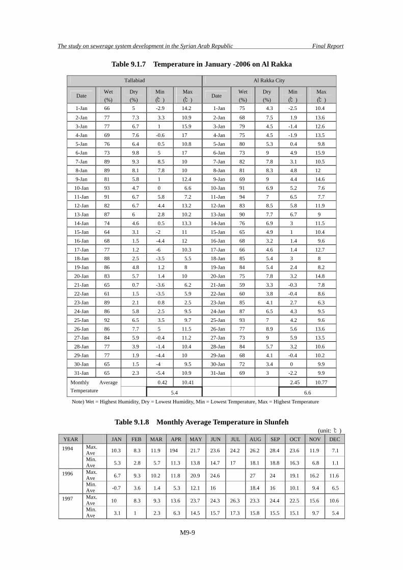
(6) Temperature There are several sewage treatment methods with easy O&M activities, and these are the Stabilization Pond Method, the Trickling Filter Method, and the Gravel Contact Oxidation Method. However, as the treatment performance of each of these processes is largely affected by temperature, temperature stands as one of the most important design conditions. The performance of the Trickling Filter and Gravel Contact Oxidation methods are affected by temperature over a certain number of days. On the contrary, the performance of the Stabilization Pond with long retention time is affected by the Monthly Average Temperature. According to the temperature data provided by the Raqqa Governorate, the monthly average temperature in Tallabiad, located north of the Governorate was 5.4℃, while that of Raqqa City was 6.6℃. Refer to Table 9.1.7:
The study on sewerage system development in the Syrian Arab Republic Final Report
M9-9
Table 9.1.7 Temperature in January -2006 on Al Rakka
Tallabiad Al Rakka City
Date Wet (%)
Dry (%)
Min (℃)
Max (℃)
Date Wet (%)
Dry (%)
Min (℃)
Max (℃)
1-Jan 66 5 -2.9 14.2 1-Jan 75 4.3 -2.5 10.4
2-Jan 77 7.3 3.3 10.9 2-Jan 68 7.5 1.9 13.6 3-Jan 77 6.7 1 15.9 3-Jan 79 4.5 -1.4 12.6 4-Jan 69 7.6 -0.6 17 4-Jan 75 4.5 -1.9 13.5 5-Jan 76 6.4 0.5 10.8 5-Jan 80 5.3 0.4 9.8 6-Jan 73 9.8 5 17 6-Jan 73 9 4.9 15.9 7-Jan 89 9.3 8.5 10 7-Jan 82 7.8 3.1 10.5 8-Jan 89 8.1 7.8 10 8-Jan 81 8.3 4.8 12 9-Jan 81 5.8 1 12.4 9-Jan 69 9 4.4 14.6
10-Jan 93 4.7 0 6.6 10-Jan 91 6.9 5.2 7.6 11-Jan 91 6.7 5.8 7.2 11-Jan 94 7 6.5 7.7 12-Jan 82 6.7 4.4 13.2 12-Jan 83 8.5 5.8 11.9 13-Jan 87 6 2.8 10.2 13-Jan 90 7.7 6.7 9 14-Jan 74 4.6 0.5 13.3 14-Jan 76 6.9 3 11.5 15-Jan 64 3.1 -2 11 15-Jan 65 4.9 1 10.4 16-Jan 68 1.5 -4.4 12 16-Jan 68 3.2 1.4 9.6 17-Jan 77 1.2 -6 10.3 17-Jan 66 4.6 1.4 12.7 18-Jan 88 2.5 -3.5 5.5 18-Jan 85 5.4 3 8 19-Jan 86 4.8 1.2 8 19-Jan 84 5.4 2.4 8.2 20-Jan 83 5.7 1.4 10 20-Jan 75 7.8 3.2 14.8 21-Jan 65 0.7 -3.6 6.2 21-Jan 59 3.3 -0.3 7.8 22-Jan 61 1.5 -3.5 5.9 22-Jan 60 3.8 -0.4 8.6 23-Jan 89 2.1 0.8 2.5 23-Jan 85 4.1 2.7 6.3 24-Jan 86 5.8 2.5 9.5 24-Jan 87 6.5 4.3 9.5 25-Jan 92 6.5 3.5 9.7 25-Jan 93 7 4.2 9.6 26-Jan 86 7.7 5 11.5 26-Jan 77 8.9 5.6 13.6 27-Jan 84 5.9 -0.4 11.2 27-Jan 73 9 5.9 13.5 28-Jan 77 3.9 -1.4 10.4 28-Jan 84 5.7 3.2 10.6 29-Jan 77 1.9 -4.4 10 29-Jan 68 4.1 -0.4 10.2 30-Jan 65 1.5 -4 9.5 30-Jan 72 3.4 0 9.9 31-Jan 65 2.3 -5.4 10.9 31-Jan 69 3 -2.2 9.9
0.42 10.41 2.45 10.77 Monthly Average Temperature 5.4 6.6
Note) Wet = Highest Humidity, Dry = Lowest Humidity, Min = Lowest Temperature, Max = Highest Temperature
Table 9.1.8 Monthly Average Temperature in Slunfeh
(unit: ℃)YEAR JAN FEB MAR APR MAY JUN JUL AUG SEP OCT NOV DEC
Max. Ave 10.3 8.3 11.9 194 21.7 23.6 24.2 26.2 28.4 23.6 11.9 7.1 1994
Min. Ave 5.3 2.8 5.7 11.3 13.8 14.7 17 18.1 18.8 16.3 6.8 1.1
Max. Ave 6.7 9.3 10.2 11.8 20.9 24.6 27 24 19.1 16.2 11.6 1996
Min. Ave -0.7 3.6 1.4 5.3 12.1 16 18.4 16 10.1 9.4 6.5
Max. Ave 10 8.3 9.3 13.6 23.7 24.3 26.3 23.3 24.4 22.5 15.6 10.6 1997
Min. Ave 3.1 1 2.3 6.3 14.5 15.7 17.3 15.8 15.5 15.1 9.7 5.4

The study on sewerage system development in the Syrian Arab Republic Final Report
M9-10
Table 9.1.8 Monthly Average Temperature in Slunfeh (unit: ℃)
YEAR JAN FEB MAR APR MAY JUN JUL AUG SEP OCT NOV DECMax. Ave 7 9.3 1998
Min. Ave 1.7 3.2
Monthly Average Temperature 5.4 5.7 6.8 40.4 17.8 19.8 21.2 21.5 21.2 17.8 11.6 7.1
Note)At Climate Observation Station on Bab Al Jannah Tomn in Slunfeh district In Slunfeh, a summer resort in a mountainous area, the monthly average temperature in January 1996 was 3℃. The average temperature over a four year period from 1994 to 1998 was 5.4℃ and corresponds with that in Tallabiad. As shown in Table 9.1.8, the temperature in Syria is very cold in the winter. Hence, the sewage treatment processes are sensitive to temperature levels and they should not be implemented in cases where the stable treated sewage quality is expected throughout the year and in cases where the treated swage is anticipated to be used for irrigation since its quality affects the aquatic environment, especially during the winter. This is due to fact that microorganism becomes inactive if temperature falls below 10℃. Refer to Table 9.1.9:
Table 9.1.9 Temperature Classification of Biological Processes
Type Temperature Range(℃)
Optimum Range Range(℃)
Psychrophilic 10-30 12-18 Mesophilic 20-50 25-40 Termphilic 35-75 55-65 Source) Fourth Edition of Metcalf & Eddy
(7) pH Added to the temperature, the pH value of sewage is also a key factor related to the growth of microorganism. The favorable pH range for bacterial growth lies between 4.0 and 9.5 and the optimum pH is 6.5 to 7.5. As shown in Table 9.1.10, the annual average pH of inflow was observed to be 8.0 at the Adraa STP in 2006. It was a little higher than the optimum range but lies within the tolerable range. In the application of the Conventional Extended Aeration Method, since the pH has the tendency to fall due to the act of excessive aeration, great care should be taken. Therefore, this is categorized as a relatively difficult method to adopt in terms of air control in the reactor.

The study on sewerage system development in the Syrian Arab Republic Final Report
M9-11
Table 9.1.10 pH of Incoming Sewer to Adraa STP
Date pH 2006/1/15 8.12006/3/2 7.82006/4/3 7.82006/5/16 7.82006/6/1 8.02006/7/16 7.82006/8/21 7.92006/9/4 8.22006/10/2 8.02006/11/2 8.12006/12/5 8.0Average 8.0
9.1.5.2 Applicable Sewage Treatment Methods in Syria (1) List of General Treatment Method Based on the existing aquatic environment in the M/P priority areas, the required level of sewage treatment shall be “Secondary Treatment”. General Biological Treatment Methods classified as secondary treatment are shown in Table 9.1.11. They have been adopted worldwide and possess long operational histories.
Table 9.1.11 Biological Sewage Treatment Methods
Status of Sewage Classification Treatment Methods Aerobic condition
Suspended-growth on sludge status
Activated sludge process -Conventional - Step aeration -Conventional extended aeration -Oxidation ditch (extended aeration) -Pure oxygen -Sequencing batch reactor
Aerated lagoon Trickling filters
Submerged Attached Growth Processes
Attached-growth on sludge status
Activated Bio filter process Stabilization pond Maturation pond Plant-based process Wet Land Aerobic to Anaerobic condition
Stabilization pond Facultative pond
Anaerobic condition Stabilization pond Anaerobic pond Attached-growth on sludge
status Anaerobic filter process
Anoxic Suspended-growth on sludge status
Suspended-growth de-nitrification
Attached-growth on sludge status
Fixed-film de-nitrification
(2) Applicable Treatment Methods Processes with high optimal values shall be identified from the general methods shown in Table 9.1.11 based on recent studies and the required conditions in the course of design. The applicable methods are as follows:

The study on sewerage system development in the Syrian Arab Republic Final Report
M9-12
1) Conventional Activated Sludge Method 2) Conventional extended aeration Method 3) Oxidation Ditch Method (one of Extended Aeration Method) 4) Constructed Wet Land Method 5) Submerged Attached Growth Method
The reasons of selection for various processes are as follows: • 1) The Conventional Activated Sludge Method and 2) the Conventional Extended
Aeration Method have been recently studied and recently adopted by the MHC and MLAE
• 3) The Oxidation Ditch Method requires an easy O&M and involves denitrification. It has been studied as a part of the F/S in Banias and will also be studied in near future as well by the GTZ. Since water resource pollution is one of the key issues in Syria, the OD method could provide the solution.
• Although performance analysis data is insufficient, 4) the Constructed Wet Land Method, has been operated in Rural Damascus and Thawra in Raqqa, and seems to have manifested good treatment efficiency. Therefore, this method was added to the other four advanced treatment methods.
• 5) The Submerged Attached Growth Method is easy in terms of O&M, because no return sludge is needed. Moreover, it is suitable for locations where the available STP site is small. In addition, denitrification is also possible in the application of this process that could serve as a substitute to the OD. This is also widely practiced as an on-site system in Japan. It is also quite applicable for small-scale target areas and could be operated without the continued presence of an operator. Thus, this method was added to the four abovementioned advanced treatment methods.
Special considerations in method selection and the reasons for the exclusion of other methods are presented below: • The reasons for selecting the Constructed Wet Land Method and Submerged Attached
Growth Method are attributed to the following background. • In Syria, large-scale STPs have been constructed. On the other hand, several small-scale
STPs employing Conventional Extended Aeration Method with capacities less than 1,000 m3/d have been implemented to prevent water pollution. However, some STPs are not operated at all or operated without a feeding return-sludge. Obviously, the shortage of human resource is a major cause in such cases. Hence in the future, STPs with capacities less than 1,000 m3/d should adopt the Wet Land Method and/or Submerged Attached Growth Method that are widely popular in Japan as on-site facilities, instead of the activated sludge methods that require return sludge management. Consequently, the economic burden for the relevant Ministries would be relieved.

The study on sewerage system development in the Syrian Arab Republic Final Report
M9-13
• Though Trickling filters, Stabilization Pond and Aerated Lagoon are advantageous with respect to O&M, these methods are directly affected by low temperatures in winter and result in poor performance. Moreover, the Aerated Lagoon Method has exhibited low power efficiency and has failed in the Allepo Governorate.
• In the Study for Zabadani conducted by the EIB, the Biological Nitrogen Removal Method was proposed because only a small parcel of land was available for the construction of the STP. This process requires a complicated and sensitive operation to feed micro-organisms. Moreover, whenever the incoming BOD load is unstable, such as in the case of tourism spots, operation becomes even further difficult. As the OD and Submerged Attached Growth Method are also applicable for denitrification, this method was excluded from the comparative study.
In selecting the appropriate method for adoption, the nitrification or denitrification capabilities of the methods were carefully examined. Though the Conventional Activated Sludge Method has an inferior nitrification or denitrification capacity compared to the other four methods, this method requires a smaller land area and proves efficient if the treated sewage is discharged into the public water bodies that are not closed water bodies. Therefore, this was chosen as the target method for the comparative study. (3) Profile of Treatment Methods 1) Conventional Activated Sludge Method This is the most basic Activated Sludge Method. Settled sludge and return activated sludge (RAS) are mixed and aerated by diffused air or mechanical aeration equipment through several compartments. Organic matter would be absorbed and consumed by the activated sludge. Finally, the increased flocculated sludge solids are separated in the secondary settling tank. This method is suitable for large-scale treatment plants that require the highly stable performance of the treated quality sewage and that have compact sites. On the other hand, the construction cost and O&M expenditure in this case are relatively higher than those of the other methods because of the number of experienced operators required, the daily inspection of equipment, the treatment of sludge generated in both primary and secondary clarifiers, and so on.
Figure 9.1.1 Schematic Drawing of Conventional Activated Sludge Method
Sludge
Influent
Sludge Return Activated Sludge
Effluent
Aeration Tank Secondary Clarifier

The study on sewerage system development in the Syrian Arab Republic Final Report
M9-14
2) Conventional Extended Aeration Method This is one of the Activated Sludge Methods. As the primary settlement is omitted, the high concentration of organic matter is biologically treated and therefore, the aeration tank should be larger, approximately three times that of the conventional activated sludge method. Characteristics are as follows: • This method requires a huge power consumption, but generates a small amount of sludge.
Therefore it is applicable for small-scale plants. • O&M is relatively easy but presents difficulties in controlling the air volume and the RAS
according to the concentration of the incoming sewage, steps that are necessary to avoid the disorganization of the activated sludge due to over-aeration.
• Less odor
Figure 9.1.2 Schematic Drawing of Conventional Extended Aeration Method 3) Oxidation Ditch Method (a kind of extended aeration) This is also another type of the Activated Sludge Method; one of the Extended Aeration Method. Reactor is an oval-shaped channel equipped with a mechanical aeration device. The sewage is passed through a screen and grit removal chamber and subsequently made to enter the reactors, until finally aerated and circulated. Mechanical Aerators are divided into two groups to include the Mechanical Aerators with Vertical Axis and Mechanical Aerators with Horizontal Axis. These are further subdivided into surface and submerged aerators although, in the OD method, the Surface Mechanical Aerators is commonly applied.
Sludge Return Activated Sludge
Effluent Secondary clarifier
Influent Aeration Tank

The study on sewerage system development in the Syrian Arab Republic Final Report
M9-15
Figure 9.1.3 Schematic Drawing of Oxidation Ditch Method Its salient features are as follows: • Performance of treatment is stable because of the low-loaded operation and the even
allocation of aerobic zone and anaerobic zone. The O&M can be easily implemented, even if difficulties are encountered in the availability or the mobilization of skilled operators in the local branches of the Ministry in charge. The OD could provide a better solution.
• Nitrification and denitrification could be carried out using this process. • Less odor • In the case of the combined sewer system, the sewage diluted by rain does not harm the
biological process. • Quantity of excess waste sludge is small and stable in the fermentation of organic matter. • In Japan, the construction cost is almost same as the other processes in case of small STP.
4) Constructed Wet Land Method The Constructed Wet Land Method is a simple and yet well-designed method that applies the self-purification capacity of reedy grass. The Constructed Wet Land Method consists of a reed bed and primary sedimentation tank which reduce the load on the reed bed for the fermentation of organic matter. The main characteristics of this process are as follows: As this system is simple, its O&M is very easy and correspondingly, the construction cost and O&M expenditure are very small. However, this process requires vast areas of land. So this method is suitable for rural towns where sizeable land areas are available and the population is small.
Sludge Return Activated Sludge
Secondary clarifierInfluent
Influent
Return Activated Sludge Sludge
Secondary clarifierReaction channel
Effluent
Effluent
Reaction channel

The study on sewerage system development in the Syrian Arab Republic Final Report
M9-16
Figure 9.1.4 Schematic Drawing of Constructed Wet Land Method
5) Submerged Attached Growth Method This is one of the attached growth methods that employs a package of bio-film (generally a plastic media). As the bio-film is submerged in the aeration tank, organic matters will be absorbed on the biological layer grown on the surface of the film through the action of metabolism. Characteristics of this process are as follows: • O&M is easy because no RAS is needed. • By selecting materials with larger surface areas for the bio-film, the treatment would be
flexible enough to accommodate the fluctuations of incoming sewage flow and organic load.
• Quantity of excess sludge is very small and stable in the fermentation of organic matter. • The use of the bio-film might cause clogging because of the thickening of the biological
layer in cases where the plant is operated under higher loading conditions. Primary clarifier can be omitted in small-scale plant such as on-site facility.
Figure 9.1.5 Schematic Drawing of Submerged Attached Growth Method (4) Sludge Treatment Processes Sludge Treatment Processes should be selected carefully for the safer treatment of the generated sludge and re-use of treated sludge. Sludge treatment processes may be proposed as the sewage treatment method described below:
Collection Pipe
Distribution Pipe
Sludge
Influent Primary clarifier
Effluent
Reed bed
Sludge
Influent Primary clarifier
Sludge
Effluent
Aeration Tank Secondary clarifier
packing for biofilm

The study on sewerage system development in the Syrian Arab Republic Final Report
M9-17
Generated sludge that settle in the sedimentation tanks of the Conventional Activated Sludge Method, the Constructed Wet Land Method and the Submerged Attached Growth Method can be treated by means of the Gravity Thickening + Anaerobic Digestion + Drying Bed, if the treated sludge is to be re-used as compost. However, in the case of the Constructed Wet Land Method where the generated sludge volume is relatively small, this can be treated by Gravity Thickening + Drying Bed + Landfill. In the future, regional sludge treatment can be one option. As the generated sludge of the Conventional Extended Aeration Method and the OD Method has low settling characteristics, it cannot be thickened efficiently by means of Gravity Thickening. In the case of the Drying Bed that is applicable if there is enough land for the STP, the sludge can be thickened through the use of the Mechanical Thickening Equipment in subsequent dry bed processes. Since the thickened sludge is stable in nature, it can be treated by means of the Drying Bed for re-use as soil improvement additive, for reclamation, or as the base material for compost. If land for the Drying Bed is not available, Mechanical Dewatering with gravity thickener for sludge reservation shall be applied. Further, if there is a large STP existing nearby, the stored sludge can be transferred to this plant. 9.1.5.3 Applicable Sewage Treatment Method for Seven Governorates (1) Strategy on Sewage Treatment Plant Planning The optimum method for sewage treatment shall be selected considering the following factors that pertain to external conditions and general knowledge:
• Load Fluctuation: The fluctuation in the quantity and quality of incoming sewage should be prudently considered to facilitate stable operations and reliable performance. Peak flow occurs once a day between 5:30 pm and 9:30 pm. Though the peak factor is small and ranges from 1.5 to 1.6, the peak duration is long.
• System Composition and Aeration Time: A simpler system composition is preferred. As Syrian working hours begin at 8:00 a.m. and ends at 3:30 p.m., it could not cover the O&M activities that transpire during the peak flow time. Therefore, simple and stable treatment methods with longer retention time are more applicable for this kind of load fluctuation including peak flow.
• Treated sewage quality satisfies effluent regulations • Small sludge volume • Environmentally acceptable disinfection: The disinfection process should not be too
complicated. Chlorination is not applicable if the treated sewage is to be re-used for irrigation.
• Reuse of treated sewage: As the purpose of treating the sewage is irrigation, the

The study on sewerage system development in the Syrian Arab Republic Final Report
M9-18
treatment method that incorporates the denitrification process and has a longer retention time is preferable.
• Odor Problem: There are various sources of odor, among which are incoming wastewater, screenings, anaerobic stabilization pond, the anaerobic sludge digester, the sludge thickening tank and primary sedimentation tank, it follows that the layout of these facilities should be carefully examined to enable the installation of odor control mechanisms. As screenings emit strong odors and are frequently found near the screen facilities in STPs in other countries, the prompt and adequate disposal of screenings can be effective countermeasure in containing the odor problem.
• Operation: A technically complicated system is not applicable. Simpler systems should be adopted.
• Construction: Though complicated structures like sludge digesters and gas tanks were constructed by local contractors, simpler structure are preferable.
• Operation of equipment: Complicated equipment are not indicated either. Simpler equipment account for easier maintenance.
• Cost: For the purpose of curtailing construction costs, some authorities think highly of “the cheaper the better” but on the contrary, the total cost must be examined. The total cost is inclusive of construction as well as O&M costs. In general, the efficient life of sewage facilities is 35 years, and the O&M costs over this period should be included in calculating the total cost.
• Land for expansion: The land to be used for plant expansion shall be secured to enable the facility to cope with the impending increase of incoming sewage flow or plant upgrading.
(2) Sewage Treatment Methods The sewage treatment method should depend on the actual scale of communities prioritized for M/P preparation. And the preferred sewage treatment method should be based on local conditions are, typically, as follows:
a) In the Dar’aa and Damascus Rural Governorates, the treatment of sewage for irrigation purposes is essential. Therefore, the land to be occupied by the treatment plant should be located near the farm areas. Nitrification and denitrification are equally desirable. • Stabilization Pond is not suitable in these conditions because a big land area would
be required, and it may be difficult as well to secure an area of this dimension near the farms,
• Conventional Activated Sludge Method is not capable of performing denitrification,
• Conventional Extended Aeration Method facilitates only nitrification. As for the stabilization of the K-N, a combination of the Oxidation Ditch and Constructed Wet Land methods would yield better performance.

The study on sewerage system development in the Syrian Arab Republic Final Report
M9-19
• Consequently, the Conventional Extended Aeration Method, Oxidation Ditch Method and Constructed Wet Land Methods have been proposed.
b) In the Tartous and Lattakia Governorates that belong to a region with rich rainfall,
treated sewage is usually discharged to the water bodies. An extensive land for the location of the treatment plant is frequently difficult to secure. In this case, the Conventional Activated Sludge Method is more applicable for a large-size STP and the Conventional Extended Aeration Method and Oxidation Ditch are best for a medium-scale STP. The Submerged Attached Growth Method would be the method of choice in the mountainous areas where land acquisition is difficult as well.
c) In Rakka, Deir-Er-zor and Hasakeh, treated sewage is usually discharged to the water
bodies. Spacious lands for the location of the treatment plant are available. Here, all kinds of processes are proposed and these include the Conventional Activated Sludge Method, Conventional Extended Aeration Method, Oxidation Ditch Method and Constructed Wet Land Method. On the other hand, as the environmental assimilating capacity of the Euphrates River is huge, the application of primary treatment is possible in the initial stage of the STP construction during which time initial investments are usually restrained. In this case, the Conventional Activated Sludge Method and Constructed Wet Land Method with primary sedimentation tank are applicable. If superior treated sewage quality is needed, the Oxidation Ditch Method can be adopted, considering the ease in O&M and available human resource.
Refer to Table 9.1.12:
Table 9.1.12 Applicable Treatment Method in Seven Governorates
Items Scale of land acquisition
Aptitude for irrigation
-Dar’aa -Damascus
Rural
-Tartous -Lattakia
-Raqqa -Deir-Er-zor
-Hasakeh big high 1)Wet Land + + 2)Oxidation ditch + + + 3) Conventional
extended aeration
+ + +
4)Submerged Attached Growth Methods
+
5)Conventional Activated sludge
+ +
small low
(3) Sludge Treatment Processes Sludge Treatment Processes shall be selected considering a number of factors such as sewage treatment, urbanization status of surroundings, availability of land, etc. The Conventional Activated Sludge Method which generates a big amount of sludge, mainly adopted in large

The study on sewerage system development in the Syrian Arab Republic Final Report
M9-20
cities, most likely incorporates the sludge digestion process that reduces volume and stabilizes the nature of the generated sludge. Refer to Table 9.1.13:
Table 9.1.13 General Approach for Applicable Sludge Treatment Process
Vast Land Narrow Land/Close to the City Conventional Activated sludge
Sludge Reservoir + digestion tank + Drying Bed
Mechanical/Gravity Thickener + Mechanical Dewatering
Conventional extended aeration
Gravity Thickener /Sludge Reservoir + Drying Bed
ditto
Oxidation ditch ditto ditto Wet Land ditto ditto Submerged Attached Growth Methods
ditto ditto
(4) Final Disposal of Sludge
In STPs, the generated sludge will be dewatered to enable hauling. The final disposal of dewatered sludge could be in the form of landfill, soil improvement such as tree-planting in the desert, composting, agricultural land application, etc. Of these, agricultural land application is the most preferred disposal method because of the good agricultural prospects in Syria. Upon choosing the agricultural land application, the fermentation process is indispensable and should be undertaken to prevent production failure. Further, once the quality of the composed sludge is secured and it gains popularity among the farmers, its demand will exceed the production capacity of each STP. Therefore, the establishment of regional compost factories is proposed as a future plan. These factories could gather sludge from several STPs. The fermentation process usually requires a time frame of three months. For instance, sewage collected from five STPs may be treated using the OD method. Volumes with a capacity of 100,000 PE will have to be stored for three months to allow the fermentation process to take place. For this purpose, the dimension of the fermentation tank will be as shown in Table 9.1.14. The sludge will be mixed with chopped reed leaves and stored in the fermentation tank.
Table 9.1.14 Dimension of Fermentation Tank
Dewatered Sludge (moisture content 80%)
Dried Sludge (moisture content 60%)
Population 500,000 500,000 Wastwater LDC 100 liter 100 liter Sludge kgDS/yr 6,022,500 6,022,500 Sludge m3/yr 30,113 15,056 Fermenter, h=1.0~2.0m 12-25m×25m 12-20m×20m Required Land Area (ha) 100m×250m (2.5 ha) 90m×200m (1.8ha)

The study on sewerage system development in the Syrian Arab Republic Final Report
M9-21
9.2 Design Criteria for Sewerage Facilities
9.2.1 Sewer Network
(1) Design Criteria The sewer network shall be designed using the gravity system as the standard but the pumping station and force main shall also be examined in accordance with site conditions. The standardization of the gravity system is necessary in order to facilitate the pursuit of O&M activities after commissioning. However, if sewage collection by means of the gravity system is difficult to manage owing to the topographic conditions in the target area, the optimum solution shall be chosen by means of a comparative study on applicable alternatives, for instance:
1) Sewage transmission by pumping station and force main 2) Generated sewage treatment by On-site System
The sewer pipe diameter is determined based on the design’s hourly maximum sewage flow given some allowance. As the incoming sewage flow exhibits an hourly fluctuation, the design of the sewer pipe shall be based on the hourly maximum sewage flow in order to cope with this hourly fluctuation. In Syria, a combination type of sewer system has been mainly adopted. In this case, storm water and wastewater are collected by one pipe. Therefore, upon network planning, the two kinds of incoming flow must be taken into account. Sewer pipe diameter and gradient shall be appropriately determined to enable enough in-pipe flow velocity, traction force and smooth flow that will prevent stagnancy and the accumulation of sediments that result in anaerobiosis. If the sediments accumulated in the sewer, flow section and flow capacity wll decrease and the sewage develop an anaerobic status that may generate highly toxic and corrosive hydrogen sulfide gases and result in the corrosion of the sewer itself, the pumping station and STP. Accordingly, the sewage shall be designed properly in order to circumvent the problems mentioned. Major design criteria and calculation formula are described below:
• Velocity Formula For flow velocity in gravity flow, Manning’s Formula is adopted.
v =(R2/3 I1/2)/n where: v:Velocity(m/s) R:Hydraulic radius(m)= flow section divided by wetted perimeter I:Gradient (decimal fraction) n:Roughness coefficient
In case of pressured flow, Hazen-William’s Formula is applicable:

The study on sewerage system development in the Syrian Arab Republic Final Report
M9-22
v =0.84935CR0.63I0.54 where: v:Velocity(m/s) C:Velocity factor = 110 I:Hydraulic gradient (decimal fraction) R:Hydraulic radius(m)
• Minimum and maximum velocity Velocity shall be within the range of 0.8 m/s to 3.0 m/s in case of Combined Sewer
• Allowance Upon determination of sewer diameter, allowance of 100% shall be counted to design hourly maximum sewage flow.
• Earth Cover More than 1.0m from Road Surface More than 1.5m from river bottom More than 0.5m from drainage bottom More than 2.0m from railroad facility If earth cover becomes smaller, pipe installation cost becomes cheaper. Earth cover of 0.6 m is applicable where the following conditions are satisfied: • Pipe safety is certificated. • House connection can be connected to the sewer pipe. • Permission of the road supervisor can be obtained.
• Minimum diameter The minimum diameter shall be 250mm accounting the intrusion of storm water since combined system is predominant in Syria.
(2) Pipe Materials In the selection of sewer materials, consideration shall be given to the problem of pipe corrosion dealt by sulfide build up in sewers. Preference is given, therefore, to corrosion resistant and low roughness coefficient materials. There are several factories manufacturing polyvinyl chloride pipes (PVC) and polyethylene pipes (PEP) in Syria. These pipes are exceedingly superior to concrete pipes in aspects of water-tightness and durability. As quality control in the manufacture of concrete pipes has not been dully exercised in Syria, they are fragile and inferior in material character compared with the two abovementioned pipe materials. The role of sewer pipes is to transfer sewage to the STPs without any leakage. As concrete pipes are much inferior in water-tightness during pipe connection in comparison to PVC and PEP, they shall be adopted for sewer pipe in principle. Since the percentage cost of pipe materials in the total project cost is less than 20%, the total
The study on sewerage system development in the Syrian Arab Republic Final Report
M9-23
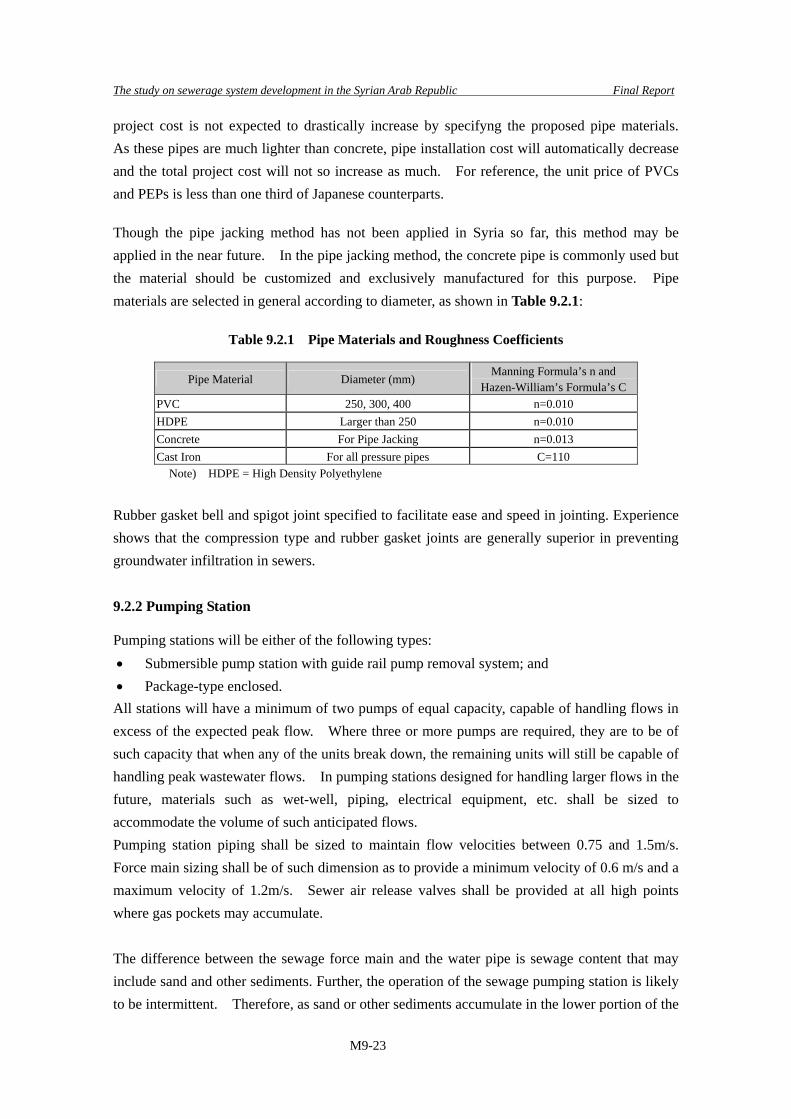
project cost is not expected to drastically increase by specifyng the proposed pipe materials. As these pipes are much lighter than concrete, pipe installation cost will automatically decrease and the total project cost will not so increase as much. For reference, the unit price of PVCs and PEPs is less than one third of Japanese counterparts. Though the pipe jacking method has not been applied in Syria so far, this method may be applied in the near future. In the pipe jacking method, the concrete pipe is commonly used but the material should be customized and exclusively manufactured for this purpose. Pipe materials are selected in general according to diameter, as shown in Table 9.2.1:
Table 9.2.1 Pipe Materials and Roughness Coefficients
Pipe Material Diameter (mm) Manning Formula’s n and
Hazen-William’s Formula’s C PVC 250, 300, 400 n=0.010 HDPE Larger than 250 n=0.010 Concrete For Pipe Jacking n=0.013 Cast Iron For all pressure pipes C=110
Note) HDPE = High Density Polyethylene
Rubber gasket bell and spigot joint specified to facilitate ease and speed in jointing. Experience shows that the compression type and rubber gasket joints are generally superior in preventing groundwater infiltration in sewers. 9.2.2 Pumping Station
Pumping stations will be either of the following types: • Submersible pump station with guide rail pump removal system; and • Package-type enclosed.
All stations will have a minimum of two pumps of equal capacity, capable of handling flows in excess of the expected peak flow. Where three or more pumps are required, they are to be of such capacity that when any of the units break down, the remaining units will still be capable of handling peak wastewater flows. In pumping stations designed for handling larger flows in the future, materials such as wet-well, piping, electrical equipment, etc. shall be sized to accommodate the volume of such anticipated flows. Pumping station piping shall be sized to maintain flow velocities between 0.75 and 1.5m/s. Force main sizing shall be of such dimension as to provide a minimum velocity of 0.6 m/s and a maximum velocity of 1.2m/s. Sewer air release valves shall be provided at all high points where gas pockets may accumulate. The difference between the sewage force main and the water pipe is sewage content that may include sand and other sediments. Further, the operation of the sewage pumping station is likely to be intermittent. Therefore, as sand or other sediments accumulate in the lower portion of the
The study on sewerage system development in the Syrian Arab Republic Final Report
M9-24
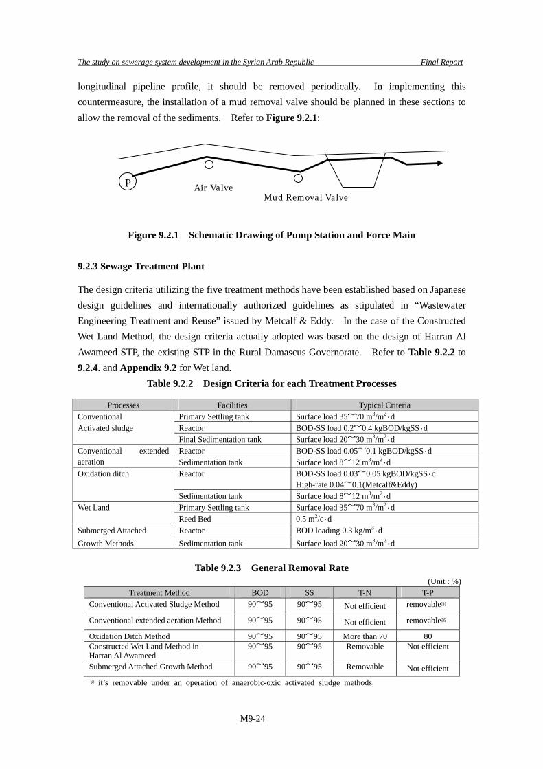
longitudinal pipeline profile, it should be removed periodically. In implementing this countermeasure, the installation of a mud removal valve should be planned in these sections to allow the removal of the sediments. Refer to Figure 9.2.1:
Figure 9.2.1 Schematic Drawing of Pump Station and Force Main 9.2.3 Sewage Treatment Plant
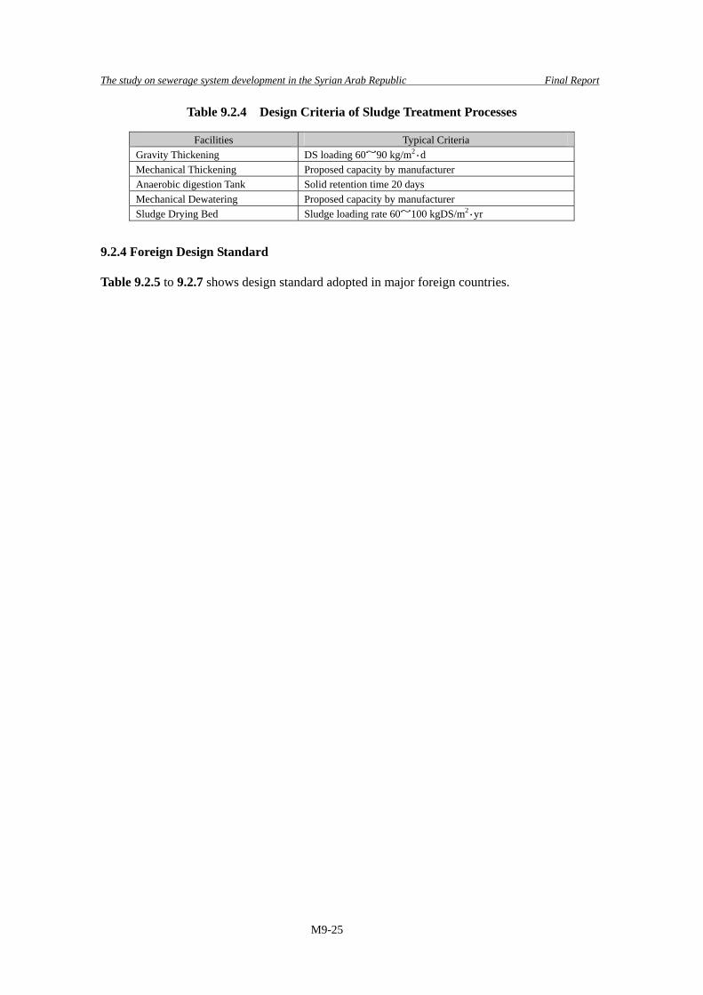
The design criteria utilizing the five treatment methods have been established based on Japanese design guidelines and internationally authorized guidelines as stipulated in “Wastewater Engineering Treatment and Reuse” issued by Metcalf & Eddy. In the case of the Constructed Wet Land Method, the design criteria actually adopted was based on the design of Harran Al Awameed STP, the existing STP in the Rural Damascus Governorate. Refer to Table 9.2.2 to 9.2.4. and Appendix 9.2 for Wet land.
Table 9.2.2 Design Criteria for each Treatment Processes
Processes Facilities Typical Criteria Conventional Primary Settling tank Surface load 35~70 m3/m2・d Activated sludge Reactor BOD-SS load 0.2~0.4 kgBOD/kgSS・d Final Sedimentation tank Surface load 20~30 m3/m2・d
Reactor BOD-SS load 0.05~0.1 kgBOD/kgSS・d Conventional extended aeration Sedimentation tank Surface load 8~12 m3/m2・d
Reactor BOD-SS load 0.03~0.05 kgBOD/kgSS・d High-rate 0.04~0.1(Metcalf&Eddy)
Oxidation ditch
Sedimentation tank Surface load 8~12 m3/m2・d Primary Settling tank Surface load 35~70 m3/m2・d Wet Land Reed Bed 0.5 m2/c・d
Submerged Attached Reactor BOD loading 0.3 kg/m3・d Growth Methods Sedimentation tank Surface load 20~30 m3/m2・d
Table 9.2.3 General Removal Rate (Unit : %)
Treatment Method BOD SS T-N T-P Conventional Activated Sludge Method 90~95 90~95 Not efficient removable※
Conventional extended aeration Method 90~95 90~95 Not efficient removable※
Oxidation Ditch Method 90~95 90~95 More than 70 80 Constructed Wet Land Method in Harran Al Awameed
90~95 90~95 Removable Not efficient
Submerged Attached Growth Method 90~95 90~95 Removable Not efficient
※it’s removable under an operation of anaerobic-oxic activated sludge methods.
P Air ValveMud Removal Valve
The study on sewerage system development in the Syrian Arab Republic Final Report
M9-25
Table 9.2.4 Design Criteria of Sludge Treatment Processes
Facilities Typical Criteria Gravity Thickening DS loading 60~90 kg/m2・d Mechanical Thickening Proposed capacity by manufacturer Anaerobic digestion Tank Solid retention time 20 days Mechanical Dewatering Proposed capacity by manufacturer Sludge Drying Bed Sludge loading rate 60~100 kgDS/m2・yr
9.2.4 Foreign Design Standard
Table 9.2.5 to 9.2.7 shows design standard adopted in major foreign countries.

The study on sewerage system development in the Syrian Arab Republic Final Report
M9-26
1D
esig
n flo
w fo
r cal
cula
tion
Hou
rly m
axim
umPe
ak fl
owPe
ak fl
ow4
~ 6
times
×D
ry w
eath
er F
low
2V
eloc
ity fo
rmul
a(G
ravi
ty fl
ow)
(Gra
vity
flow
)(G
ravi
ty fl
ow)
(Gra
vity
flow
)
Man
ning
form
ula
M
anni
ng fo
rmul
a
Man
ning
form
ula
M
anni
ng fo
rmul
a
V=C
(Ri)0.
5
Col
ebro
ok-W
hite
form
ula
V
=(R
2/3 I1/
2 )/n
V=(
R2/
3 I1/2 )/n
V
=(R
2/3 I1/
2 )/nC
=Ry /n
etc.
(Pre
ssur
ed fl
ow)
(Pre
ssur
ed fl
ow)
(Pre
ssur
ed fl
ow)
y=2.
5n0.
5 -0.1
3-0.
75R
(n0.
5 -0.1
)
Haz
en-W
illia
ms f
orm
ula
H
azen
-Will
iam
s for
mul
a
Haz
en-W
illia
ms
form
ula
V
=0.8
4935
CR
0.63
I0.54
V
=0.8
49C
R0.
63I0.
54
V=0
.849
35C
R0.
63I0.
54
3M
axim
um v
eloc
ity (V
)V
= 3
.0V
= 3
.0V
= 4
.0V
=4.0
(con
cret
e an
d st
one
linin
g)V
=2(D
)0.5
V=1
.6 (b
rick
wal
l)
V=2
.0 (s
ingl
e la
yer p
avem
ent)
V=3
.0 to
3.5
(dou
ble
laye
r pav
emen
t)4
Min
imum
vel
ocity
(V)
V =
0.8
(com
bine
d sy
stem
)V
= 0
.8V
= 0
.8V
=0.7
(150
<D<2
50m
m)
V =
0.7
5
V=0
.8 (3
00<D
<400
mm
)
V=0
.9 (4
50<D
<500
mm
)
V=1
.0 (6
00<D
<800
mm
)V
=1.1
5 (9
00<D
<1,2
00m
m)
V=1
.30
(D=1
.500
mm
)
V=1
.50
(D>1
,500
mm
)
5R
ough
ness
coe
ffic
ient
sn=
0.01
3 (C
oncr
ete)
n=0.
015
(Con
cret
e)n=
0.01
4 (g
ravi
ty fl
ow)
n=0.
010
(PV
C, P
EP)
n=0.
011
(PV
C, P
EP)
n=0.
013
(pre
ssur
e flo
w)
C=1
10 (C
ast i
ron)
C=1
00 (C
ast i
ron)
6Fl
ow a
llow
ance
100
(D<7
00m
m d
ia.)
0.8
of fu
ll at
ulti
mat
e pe
ak fl
ow0.
6 (1
50<D
<250
mm
)
50~1
00 (7
00<D
<165
0mm
dia
.)0.
7 (3
00<D
<400
mm
)25
~50
(D>1
,650
mm
dia
.)0.
75 (4
50<D
<900
mm
)
0.8
(D>1
,000
)
7M
inim
um e
arth
cov
er (H
)H
=1.0
H=1
.0 (b
ranc
h se
wer
)H
=1.2
H=0
.3 (D
<500
mm
)
H=1
.5 (t
runk
sew
er)
H=0
.5 (D
>500
mm
)H
=0.7
(pre
vent
from
free
zing
and
tr
affic
on
load
)
8M
inim
um p
ipe
diam
eter
(D)
D=2
50 (c
ombi
ned
syst
em)
D=1
50D
=225
D=2
00
9Pi
pe m
ater
ials
Rei
nfor
ced
conc
rete
pip
eR
einf
orce
d co
ncre
te p
ipe
Vitr
ified
cla
y pi
peR
einf
orce
d co
ncre
te p
ipe
Asb
esto
s ce
men
t pip
eC
oncr
ete
pipe
Prec
ast c
oncr
ete
pipe
Rei
nfor
ced
conc
rete
pip
eN
onpr
essu
re c
oncr
ete
pipe
Cla
y pi
pe
Man
ufac
ture
d re
ctan
gula
r con
duits
Plas
tic p
ipe
Duc
tile
iron
pipe
Cer
amic
pip
eC
oncr
ete
pipe
Poly
viny
l chl
orid
e pi
peC
ast i
ron
pipe
Stee
l pip
eC
ast i
ron
pipe
Box
cul
vert
Cla
y pi
peSt
eel p
ipe
Poly
ethy
lene
pip
eA
sbes
tos c
emen
t pip
eD
uctil
e iro
n pi
peFi
ber r
einf
orce
d pl
astic
pip
eC
lay
pipe
Gla
ss re
info
rced
pla
stic
pip
ePl
astic
pip
eG
lass
rein
forc
ed p
last
ic p
ipe
Poly
ethy
lene
pip
eA
sbes
tos c
emen
t pip
eSt
eel p
ipe
Hig
h de
nsity
pol
yeth
ylen
e pi
pe
Gla
ss fi
ber r
einf
orce
d pl
astic
pip
ePo
lyvi
nyl c
hlor
ide
pipe
Stee
l pip
e
- -
m/s
ec
m/s
ec
Japa
nese
Sta
ndar
dsun
itD
esig
n C
rite
ria
Ado
pted
Val
ues
Bri
tish
Stan
dard
s (B
S)R
ussi
an S
tand
ards
(SN
IP)
Mal
aysi
an S
tand
ards
In
dian
Sta
ndar
ds (C
PHE
EO
)
---
%-
- - - -
m mm
Tabl
e
9.2.
5 C
ompa
riso
n Ta
ble
on th
e D
esig
n C
rite
ria
of S
ewer
Net
wor
k (1
/2)

The study on sewerage system development in the Syrian Arab Republic Final Report
M9-27
10M
anho
le d
iam
eter
(P)
P=90
0 (D
<600
)de
pth
= H
P=1,
200m
m (2
25<D
<300
)P=
1,00
0 (D
<600
mm
)m
in. s
ize
of c
ham
ber =
1.0
5P=
1,20
0 (7
00<D
<900
)P=
900
(0.9
0<H
<1.6
5m)
P=1,
350m
m (3
75<D
<450
)P=
1,25
0 (D
=700
mm
)P=
1,50
0 (1
,000
<D<1
,100
)P=
1,20
0 (1
.65<
H<2
.30m
)P=
1,50
0mm
(600
<D<7
00)
P=1,
500
(800
<D<1
,000
mm
)
P=1,
800
(1,2
00<D
<1,3
50)
P=1,
500
(2.3
0<H
<9.0
0m)
P=2,
000
(D=1
,200
mm
)P=
1,80
0 (9
.00<
H<1
4.00
m)
P=1,
500
(pip
elin
e de
pth
> 3.
0m)
and
less
than
inte
rnal
dia
met
er o
f the
(sew
er +
150m
m o
n bo
th s
ides
)11
Man
hole
spa
cing
max
. 75
(D<6
00m
m d
ia.)
max
. 30
(D<9
00m
m d
ia.)
max
. 100
(D<1
,000
mm
dia
.)m
ax. 3
5 (D
=150
mm
)m
ax. 1
00 (D
<1,0
00m
m)
max
. 100
(D<1
,000
mm
dia
.)90
~ 1
50 (9
00<D
<1,5
00m
m d
ia.)
max
. 150
(D>1
,000
mm
dia
.)m
ax. 5
0 (2
00<D
<450
mm
)18
0 ~2
00 (1
,000
<D<1
,800
mm
)m
ax. 1
50 (D
<1,5
00m
m d
ia.)
150
~ 20
0 (1
,500
<D<2
,000
mm
dia
.)m
ax. 7
5 (5
00<D
<600
mm
)m
ax. 3
00 (D
>1,8
00m
m)
max
. 200
(D>1
,650
mm
dia
.)m
ax. 1
00 (7
00<D
<900
mm
)
max
. 150
(1,0
00<D
<1,4
00m
m)
max
. 200
(1,5
00<D
<2,0
00m
m)
mm m
Mal
aysi
an S
tand
ards
R
ussi
an S
tand
ards
(SN
IP)
Bri
tish
Stan
dard
s (B
S)A
dopt
ed V
alue
sD
esig
n C
rite
ria
unit
Japa
nese
Sta
ndar
dsIn
dian
Sta
ndar
ds (C
PHE
EO
)
Tabl
e
9.2.
5 C
ompa
riso
n Ta
ble
on th
e D
esig
n C
rite
ria
of S
ewer
Net
wor
k (2
/2)

The study on sewerage system development in the Syrian Arab Republic Final Report
M9-28
1G
rit c
ham
ber
1.1
max
. flo
w v
eloc
ity (V
)V
= 0
.3V
= 0
.15
~ 0.
30V
= 0
.2-
V =
0.3
1.2
Wat
er su
rfac
e lo
ad (W
S)W
S =
1,80
0W
S =
2,16
0W
S <
1,50
0-
-1.
3 Es
timat
ed g
rit q
uant
ity (Q
1)Q
1 =
0.00
05 ~
0.0
5-
--
Q1
= 0.
04 ~
0.2
02 (a
erat
ed ty
pe)
2Sc
reen
sys
tem
2.1
Prim
ary
scre
en M
ax. c
lear
spa
cing
(P1)
P1 =
50
~ 15
0P1
= 7
5 ~
150
(coa
rse
scre
en)
P1 =
25
P1 =
30
~ 75
P1 =
6 ~
150
Max
. vel
ocity
at s
cree
n fa
ce (V
1)V
1 =
0.45
V1
= 0.
6 ~
1.2
V1
= 1.
0-
V1
= 0.
3 ~
0.6
(man
ual s
cree
n)2.
2 Se
cond
ary
scre
en M
ax. c
lear
spa
cing
(P2)
P2 =
15
~ 25
P2 <
20
(fin
e sc
reen
)P2
= 1
2-
P2 <
6
2.3
Estim
ated
scr
eeni
ngs
volu
me
(Q2)
Q2
= 0.
5 ~
50Q
2 =
1.5
~ 15
Q2
= 30
-Q
2 =
4.0
~ 40
3Pu
mp
equi
pmen
t3.
1 D
esig
n flo
w fo
r cal
cula
tion
Hou
rly m
axim
um fl
owPe
ak fl
ow w
ith 5
0% s
tand
byPe
ak fl
owD
ry w
eath
er fl
ow ×
3-
3.2
Type
of s
tatio
nQ
: des
ign
flow
= m
3 /min
(1) T
wo
wel
ls ty
pePE
: Pop
ulat
ion
Equi
vale
nt-
-
(1) Q
<3.2
m3 /m
in (
2 un
its)
W
et w
ell f
or s
torin
g se
wag
e an
d(1
) Cas
e of
PE<
5,00
0M
anho
le ty
pe
dry
wel
l for
set
ting
pum
psW
et w
ell w
ith s
ubm
ersi
ble
(2) 3
.2<Q
<6~8
m3 /m
in (2
~5 u
nits
)(2
) One
wel
l typ
epu
mp
(2 u
nits
)Sm
all s
cale
type
with
out g
rit
Use
of w
et-p
it pu
mp
(sub
mer
sibl
e(2
) Cas
e of
5,0
00<P
E<10
,000
cham
ber a
nd sc
reen
pu
mp)
Wet
wel
l or d
ry w
ell (
2uni
ts)
(3) Q
>6~8
m3 /m
in (2
~5 u
nits
)(3
) Cas
e of
PE>
10,0
00C
onve
ntio
nal t
ype
Wet
wel
l and
dry
wel
l10
,000
<PE<
20,0
00
2~4
units
PE>2
0,00
0 6
uni
ts
3.3
Prop
osed
pum
p di
amet
er (D
)D
= 1
46(Q
/V)0.
5-
--
-w
here
Q: d
isch
argi
ng fl
ow (m
3 /min
)V
: Vel
ocity
at s
uctio
n=
1.5
~ 3.
0 m
/sec
3.3
Ret
entio
n tim
e of
wet
wel
l (T)
T =
4 (in
cas
e of
man
hole
type
)T
= 5
T =
30 m
inut
es in
ave
rage
flow
T =
5 ~
10-
4Fo
rce
mai
nm
in. d
iam
eter
(D)
D =
80
D =
100
D=1
00D
= 1
00-
Des
ign
Cri
teri
aun
itJa
pane
se S
tand
ards
Indi
an S
tand
ards
(CPH
EE
O)
Mal
aysi
an S
tand
ards
B
ritis
h St
anda
rd C
ode
Was
tew
ater
Eng
inee
ring
(Met
calf
& E
ddy)
Ado
pted
Val
ues
m/s
m3 /m
2 /day
m3 /1
03 m3
mm
m/s
ec
mm
m3/
106 m
3
- - mm
min
mm
Tabl
e
9.2.
6 C
ompa
riso
n Ta
ble
on th
e D
esig
n C
rite
ria
of P
umpi
ng S
tatio
n

The study on sewerage system development in the Syrian Arab Republic Final Report
M9-29
1A
pplic
able
sew
age
treat
men
t met
hods
(1) C
onve
ntio
nal a
ctiv
ated
slud
ge(1
) Con
vent
iona
l act
ivat
ed sl
udge
(1) T
rickl
ing
filte
r(f
or sm
all s
ewag
e tre
atm
ent w
orks
)(1
) Con
vent
iona
l act
ivat
ed s
ludg
e(2
) Oxy
gen
activ
ated
slud
ge(2
) Com
plet
ely
mix
ed(2
) Rot
atin
g bi
olog
ical
con
tact
or(1
) Ext
ende
d ae
ratio
n(2
) Mod
ified
act
ivat
ed sl
udge
(3) C
onta
ct a
erat
ion
(3) E
xten
ded
aera
tion
(3) S
ubm
erge
d bi
olog
ical
con
tact
or(2
) Con
tact
stab
iliza
tion
(3) E
xten
ded
aera
tion
(4) O
xida
tion
ditc
h(4
) Oxi
datio
n di
tch
(4) S
tabi
lizat
ion
pond
(3) O
xida
tion
ditc
h(4
) Oxi
datio
n di
tch
(5) E
xten
ded
aera
tion
(5) A
erat
ed la
goon
(5) A
erat
ed la
goon
(4) R
otar
y bi
olog
ical
con
tact
ors
(5) S
eque
nce
batc
h re
acto
r(6
) Bio
logi
cal a
erat
ed fi
lter
(6) T
rickl
ing
filte
r(6
) Con
vent
iona
l act
ivat
ed s
ludg
e(6
) Tric
klin
g fil
ter
(7) A
dvan
ced
treat
men
t(7
) Rot
atin
g bi
olog
ical
con
tact
or(7
) Ext
ende
d ae
ratio
n(7
) Aer
ated
lago
on(8
) Tric
klin
g fil
ter
(8) S
tabi
lizat
ion
pond
(8) O
xida
tion
ditc
h(8
) Sta
biliz
atio
n po
ndet
c.(9
) Upf
low
ana
erob
ic sl
udge
bla
nket
(9) S
eque
nce
batc
h re
acto
r(9
) Rot
atin
g bi
olog
ical
con
tact
or
etc.
etc.
(10)
Wet
land
etc.
2Sc
reen
and
grit
cha
mbe
rre
fer t
o th
e sh
eet o
f pum
p st
atio
nre
fer t
o th
e sh
eet o
f pum
p st
atio
nre
fer t
o th
e sh
eet o
f pum
p st
atio
nre
fer t
o th
e sh
eet o
f pum
p st
atio
n
3Pr
imar
y se
dim
enta
tion
tank
Det
entio
n tim
e (T
)T
= 1.
5T
= 2.
0 ~
2.5
T =
2 ho
urs i
n pe
ak fl
owT
= 2.
0W
ater
sur
face
load
(WS)
WS
= 35
~ 7
0W
S =
35 ~
50
WS
= 30
~ 4
5 in
pea
k flo
wW
S =
33 ~
49
Efflu
ent w
eir l
oad
(EW
)EW
= 2
50EW
= 1
25EW
= 1
00 ~
200
EW =
124
~ 4
96W
ater
dep
th (H
)H
= 2
.5 ~
4.0
H =
2.5
~ 3
.5-
H =
3.0
5 ~
4.6
4Ty
pica
l sec
onda
ry tr
eatm
ent p
roce
ss4.
1C
onve
ntio
nal a
ctiv
ated
slud
ge (C
AS)
BO
D-S
S lo
ad (L
)L
= 0.
2 ~
0.4
L =
0.3
~ 0.
4L
= 0.
25 ~
0.5
0L
= 0.
2 ~
0.4
Hyd
raul
ic re
tent
ion
time
(HR
T)H
RT
= 6
~ 8
HR
T =
4 ~
6H
RT
= 6
~ 16
HR
T =
4 ~
8O
xyge
n re
quire
men
t (O
)O
= 1
.62
O =
0.8
~ 1
.0O
= 1
.5-
Mix
ed li
quor
susp
ende
d so
lids (
MLS
S)M
LSS
= 1,
500
~ 2,
000
MLS
S =
1,50
0 ~
3,00
0M
LSS
= 1,
500
~ 3,
000
(typi
cal =
2,5
00)
MLS
S =
1,20
0 ~
3,00
0Sl
udge
age
(SA
)SA
= 3
~ 6
SA =
5 ~
8SA
= 5
~ 1
0SA
= 5
~ 1
5M
in. m
ixin
g po
wer
requ
irem
ent (
P)-
-P
= 20
-W
ater
dep
th (H
)H
= 4
~ 6
H =
3.0
~ 4
.5H
= 3
.0 ~
5.0
(diff
used
aer
ator
type
)H
= 4
.57
(diff
used
aer
ator
type
)4.
2Ex
tend
ed a
erat
ion
(EA
)B
OD
-SS
load
(L)
L =
0.05
~ 0
.10
L =
0.1
~ 0.
18L
= 0.
05 ~
0.1
0L
= 0.
05 ~
0.1
5L
= 0.
05 ~
0.1
5
Hyd
raul
ic re
tent
ion
time
(HR
T)H
RT
= 16
~ 2
4H
RT
= 12
~ 2
4H
RT
= 18
~ 2
4H
RT
= 24
~ 4
8H
RT
= 18
~ 3
6O
xyge
n re
quire
men
t (O
)O
= 1
.4 ~
2.2
O =
1.0
~ 1
.2O
= 1
.5 ~
2.0
O =
2.0
-M
ixed
liqu
or su
spen
ded
solid
s (M
LSS)
MLS
S =
3,00
0 ~
4,00
0M
LSS
= 3,
000
~ 5,
000
MLS
S =
2,50
0 ~
5,00
0M
LSS
= 2,
000
~ 5,
000
MLS
S =
1,50
0 ~
5,00
0Sl
udge
age
(SA
)SA
= 1
3 ~
50SA
= 1
0 ~
25SA
= >
20
-SA
= 2
0 ~
30M
in. m
ixin
g po
wer
requ
irem
ent (
P)-
-P
= 20
--
Wat
er d
epth
(H)
H =
4 ~
6H
= 3
.0 ~
4.5
H =
3~5
(diff
used
aer
ator
type
)H
= 2
.0 ~
3.5
H =
4.5
7 (d
iffus
ed a
erat
or ty
pe)
4.3
Rot
atin
g bi
olog
ical
con
tact
or (R
BC
)To
tal B
OD
spe
cific
load
(TL)
TL =
5 ~
7-
TL =
5 ~
10
TL =
5.0
~ 7
.5TL
= 3
.7 ~
9.8
Det
entio
n tim
e (T
)-
T =
1.0
~ 1.
5T
= 2
hour
s in
aver
age
flow
-T
= 0.
7 ~
1.5
Dis
c di
amet
er (D
)D
= 3
.0 ~
4.0
D =
1.0
~ 4
.0D
= 2
.5 ~
3.5
--
Max
. per
iphe
ral v
eloc
ity (V
)V
= 0
.3le
ss th
an 1
0 rp
mV
= 0
.3V
< 0
.35
-D
epth
of d
isc
subm
erge
nce
(H)
H =
35
~ 45
H =
40
~ 60
H =
40
~ 90
-H
= 4
0
Des
ign
Cri
teri
aun
itJa
pane
se S
tand
ards
Indi
an S
tand
ards
(CPH
EE
O)
Mal
aysi
an S
tand
ards
B
ritis
h St
anda
rd C
ode
Was
tew
ater
Eng
inee
ring
(Met
calf
& E
ddy)
Ado
pted
Val
ues
-
hour
m3 /m
2 /day
m3 /m
/day
- m
kgB
OD
/kgS
S
hour
kgO
2/kg
BO
D
mg/
lda
y
w/m
3
m
kgB
OD
/kgS
S
hour
kgO
2/kg
BO
D
mg/
lda
y
w/m
3
m
g/m
2 /day
hour m
m/s
ec%
Tabl
e
9.2.
7 C
ompa
riso
n Ta
ble
on th
e D
esig
n C
rite
ria
of S
ewer
age
Trea
tmen
t Pla
nt (1
/3)

The study on sewerage system development in the Syrian Arab Republic Final Report
M9-30
4.4
Tric
klin
g fil
ter (
TF)
-O
L =
0.08
~ 0
.32
(low
rate
)O
L =
0.08
~ 0
.15
(low
rate
)O
L =
0.08
~ 0
.40
(low
rate
)O
L <
1.2
(hig
h ra
te)
OL
= 0.
32 ~
1.0
(hig
h ra
te)
OL
= 0.
50 ~
2.0
0 (h
igh
rate
)O
L =
0.48
~ 0
.96
(hig
h ra
te)
-H
L =
1.0
~ 4.
0 (lo
w ra
te)
HL
= 1.
0 ~
4.0
(low
rate
)H
L =
0.94
~ 3
.74
(low
rate
)H
L =
15.0
(hig
h ra
te)
HL
= 10
.0 ~
40.
0 (h
igh
rate
)H
L =
10.0
~ 4
0 .0
(hig
h ra
te)
HL
= 9.
35 ~
37.
4 (h
igh
rate
)SY
= 0
.5 (l
ow ra
te)
SY =
1.0
(hig
h ra
te)
H =
1.8
~ 3
.0 (l
ow ra
te)
H =
1.8
3 ~
2.44
(low
rate
)H
= 0
.9 ~
2.5
(hig
h ra
te)
H =
0.9
1 ~
1.83
(hig
h ra
te)
4.5
Sequ
ence
bat
ch re
acto
r (SB
R)
BO
D-S
S lo
ad (L
)L
= 0.
03 ~
0.4
0L
= 0.
05 ~
0.3
0L
= 0.
05 ~
0.3
0Sl
udge
age
(SA
)-
SA =
10
~ 30
-Sl
udge
yie
lds
(SY
)-
SY =
0.7
5 ~
1.10
-M
ixed
liqu
or su
spen
ded
solid
s (M
LSS)
MLS
S =
1,50
0 ~
4,00
0M
LSS
= 3,
000
~ 6,
000
-C
ycle
tim
e (T
)-
T =
4 ~
8M
LSS
= 1,
500
~ 5,
000
Dec
ant t
ime
(DT)
-D
T >
1.0
-W
ater
dep
th (H
)H
= 4
~ 5
-H
= 4
.57
(diff
used
aer
ator
type
)4.
6O
xida
tion
ditc
h (O
D)
BO
D-S
S lo
ad (L
)L
= 0.
03 ~
0.0
5L
= 0.
1 ~
0.18
L =
0.05
~ 0
.15
L =
0.05
~ 0
.30
Hyd
raul
ic re
tent
ion
time
(HR
T)H
RT
= 24
~ 4
8H
RT
= 12
~ 2
4H
RT
= 24
~ 4
8H
RT
= 8
~ 36
Oxy
gen
requ
irem
ent (
O)
O =
1.4
~ 2
.2O
= 1
.0 ~
1.2
O =
2.0
-M
ixed
liqu
or su
spen
ded
solid
s (M
LSS)
MLS
S =
3,00
0 ~
4,00
0M
LSS
= 3,
000
~ 5,
000
MLS
S =
2,00
0 ~
5,00
0M
LSS
= 1,
500
~ 5,
000
Slud
ge a
ge (S
A)
SA =
8 ~
50
SA =
10
~ 25
-SA
= 1
0 ~
30M
in. m
ixin
g po
wer
requ
irem
ent (
P)-
--
-W
ater
dep
th (H
)H
= 1
~ 3
(in
case
of s
urfa
ce m
ixer
)H
= 3
.0 ~
4.5
H =
1.0
~ 3
.0H
= 4
.57
(diff
used
aer
ator
type
)4.
7Fa
culta
tive
aera
ted
lago
on (A
L)D
eten
tion
time
(T)
T =
3 ~
5T
= 3
~ 6
Wat
er d
epth
(H)
H =
2.5
~ 5
.0H
< 3
.7 (s
urfa
ce a
erat
or)
Land
requ
irem
ent (
A)
A =
0.1
5 ~
0.30
-Po
wer
requ
irem
ent (
P)P
= 12
~ 1
5-
5Se
cond
ary
sedi
men
tatio
n ta
nk5.
1In
cas
e of
CA
SM
in. s
ide
wat
er d
epth
(H)
H =
2.5
~ 4
.0H
= 3
.5 ~
4.5
H =
3.0
H =
3.7
~ 6
.1H
ydra
ulic
rete
ntio
n tim
e (T
)-
T =
1.5
~ 2.
0T
= 2.
0-
Wat
er s
urfa
ce lo
ad (W
S)W
S =
20 ~
30
WS
= 15
~ 3
5W
S =
< 30
in p
eak
flow
WS
= 16
.3 ~
32.
6Ef
fluen
t wei
r loa
d (E
W)
EW =
150
EW =
185
EW =
150
~ 1
80EW
= 2
505.
2In
cas
e of
OD
, EA
Min
. sid
e w
ater
dep
th (H
)H
= 3
.0 ~
4.0
H =
3.5
~ 4
.5-
H =
3.7
~ 6
.1H
ydra
ulic
rete
ntio
n tim
e (T
)T
= 6
~ 12
T =
1.5
~ 2.
0T
= 2.
0-
Wat
er s
urfa
ce lo
ad (W
S)W
S =
8 ~
12W
S =
8 ~
15W
S <
22.0
(pea
k flo
w)
WS
= 8.
2 ~
16.3
Efflu
ent w
eir l
oad
(EW
)EW
= 5
0EW
= 1
85EW
= 1
50EW
= 1
20
H =
1.5
~ 2
.0H
= 1
.5
kgB
OD
/kgS
S
day
kgSS
/kgB
OD
Org
anic
load
(OL)
Hyd
raul
ic lo
ad (H
L)
Slud
ge y
ield
s (S
Y)
Min
. dep
th (H
)
Mal
aysi
an S
tand
ards
B
ritis
h St
anda
rd C
ode
Was
tew
ater
Eng
inee
ring
(Met
calf
& E
ddy)
Ado
pted
Val
ues
Des
ign
Cri
teri
aun
itJa
pane
se S
tand
ards
Indi
an S
tand
ards
(CPH
EE
O)
kgSS
/kgB
OD
m3 /d
ay/m
2
kg/d
ay/m
3
m mg/
lho
urho
ur m
kgB
OD
/kgS
S
hour
kgO
2/kg
BO
D
mg/
lda
y
w/m
3
m day m
m2 /p
erso
nkw
h/pe
rs./y
m hour
m3 /m
2 /day
m3 /m
/day
m hour
m3 /m
2 /day
m3 /m
/dayTa
ble
9.2.
7 C
ompa
riso
n Ta
ble
on th
e D
esig
n C
rite
ria
of S
ewer
age
Trea
tmen
t Pla
nt (2
/3)

The study on sewerage system development in the Syrian Arab Republic Final Report
M9-31
5.3
In c
ase
of T
FM
in. s
ide
wat
er d
epth
(H)
H =
2.5
~ 3
.5H
= 3
.0 ~
4.5
Hyd
raul
ic re
tent
ion
time
(T)
T =
1.5
~ 2.
0-
Wat
er s
urfa
ce lo
ad (W
S)W
S =
15 ~
25
WS
= 16
.3 ~
24.
4Ef
fluen
t wei
r loa
d (E
W)
EW =
185
EW =
120
6D
isin
fect
ion
Chl
orin
e do
sage
(CD
)C
D =
2 ~
4C
D =
2.0
~ 8
.0C
D =
2.0
~ 8
.0C
onta
ct ti
me
(T)
T =
15T
= 30
in a
vera
ge fl
owT
= 15
~ 4
5
7G
ravi
ty s
ludg
e th
icke
ning
SL =
30
~ 50
(prim
ary
+ ac
tivat
ed)
SL =
39
~ 78
(prim
ary
+ ac
tivat
ed)
SL =
50
~ 60
(prim
ary
+ tri
cklin
g fil
ter)
SL =
59
~ 98
(prim
ary
+ tri
cklin
g fil
ter)
Tank
dep
th (H
)H
= 4
.0H
= 3
.0H
= 0
.6 ~
2.4
Slud
ge re
tent
ion
time
(T)
T =
12T
= 24
(max
imum
)-
8Sl
udge
dig
estio
nD
iges
tion
day
(T)
T =
20 ~
30
T =
10 ~
20
(hig
h ra
te)
T =
30T
= 10
~ 2
0O
rgan
ic v
olat
ile s
olid
s rat
e (O
S)O
S =
70O
S =
60 ~
85
--
Dig
estio
n ra
te (D
R)
DR
= 5
0D
R =
50
--
9Sl
udge
dew
ater
ing
Prop
osed
type
of d
ewat
erin
gB
elt p
ress
Vac
uum
filte
rB
elt p
ress
Dry
ing
bed
Bel
t pre
ss
Cen
trifu
gefil
ter p
ress
Cen
trifu
geC
entri
fuge
Filte
r pre
ssC
entri
fuge
Filte
r pre
ssFi
lter p
ress
Scre
w p
ress
etc.
Dry
ing
bed
Dry
ing
bed
Slud
ge d
epth
in d
ryin
g be
d (H
)H
< 2
00H
= 3
00H
< 3
00H
< 2
25H
= 2
00 ~
300
Ret
entio
n tim
e in
dry
ing
bed
(T)
-T
= fe
w d
ay ~
2 w
eeks
-T
= 6
~ 10
wee
ksT
= 10
~ 1
5
Bri
tish
Stan
dard
Cod
eW
aste
wat
er E
ngin
eeri
ng (M
etca
lf&
Edd
y)A
dopt
ed V
alue
s
Solid
load
(SL)
kg/m
2 /day
SL =
60
~ 90
hour
m3 /m
2 /day
m3 /m
/day
mg/
l
Des
ign
Cri
teri
aun
itJa
pane
se S
tand
ards
Indi
an S
tand
ards
(CPH
EE
O)
Mal
aysi
an S
tand
ards
m min m hour
day
day
% % - mmTa
ble
9.2.
7 C
ompa
riso
n Ta
ble
on th
e D
esig
n C
rite
ria
of S
ewer
age
Trea
tmen
t Pla
nt (3
/3)

The study on sewerage system development in the Syrian Arab Republic Final Report
M9-32
9.3 Selection of the Priority Area for Master Plan
9.3.1 Lattakia Governorate
Lattakia Governorate is comprised of four major districts namely Lattakia, Jable, Al Hafeh and Al Qerdaha in order of population. As aforementioned in the previous chapter, Lattakia and Jable is contained in the EU supported “Protecting Mediterranean from land-based Pollution Program” and Feasibility Report of Pre-investment Study was completed on June 2005. Therefore, these two districts can be excluded from Master Plan priority area. According to the Census, the population of 2004 in Al Hafeh and Al Qerdaha was as shown in Table 9.3.1.
Table 9.3.1 Population in 2004
Name of District
Population in 2004
Service Ratio
Served Population
M/P Priority
Al Hafeh 81,213 83% 67,407 ○ Al Qerdaha 75,279 77% 57,965 △
As both districts have no treatment facilities, the raw sewage has been discharged into channels, rivers or valleys nearby and the magnitude of the discharged pollution load is correlative to the served population. As borne by the table, Al Hafeh with the greater number of served population has the higher priority. Al Hafeh is also comprised of several sub-districts as shown in Table 9.3.2.
Table 9.3.2 Comparison of Master Plan Priority in Lattakia Governorate
Name of Sub-district
Population in 2004
Number of Tourists
Total Population
Service Ratio
Served Population
M/P Priority
Al Hafeh Center
23,347 unknown,
but negligible24,905 80% 19,924 △
Slunfeh 19,518 *77,778 97,296 90% 87,566 ○ Kansaba 17,615 unknown 17,615 60% 10,569 △ Mzeraa 13,908 unknown 13,908 90% 12,517 △ Ayen Teneh 6,825 unknown 6,825 90% 6,143 △
*) 1,000,000/90/7 = 77,778 : Assuming that tourists stay for a week per season
Among these sub-districts, Slunfeh is the summer resort area. During the summer season from July to September, the number of tourists that flock to the resort is estimated to be 1 to 1.5 million. Even if this influx is temporary, tourists should be counted in as part of the served population. As shown in the table, Slunfeh with greatest number of served population was selected as an MP priority area. 9.3.2 Tartous Governorate
The Tartous Governorate consists of four major districts, namely Tartous, Banias, Safita,

The study on sewerage system development in the Syrian Arab Republic Final Report
M9-33
Drekeish and Al Shreikh Bader in the order of population. The construction of the STPs in Tartous City and Banias that covers the rehabilitation of the wastewater treatment plant in the oil refining facilities is contained in the scope of EU supported “Protecting Mediterranean from Land-based Pollution Program”. Therefore, Tartous can be excluded from the M/P priority area but as to Banias, the EU study only covers the Banias Center, the existing populated area along the Mediterranean Sea and the oil refining factory.
Table 9.3.3 Comparison of Master Plan Priority in Tartous Governorate
Name of District
Population in 2004
Service Ratio
Served Population
M/P Priority
Remarks
Tartous 283,571 85% 241,035 △ Studied by EU
Banias 174,233 95% 165,521 ○ Whole area shall be Studies
Safita 129,632 90% 116,669 △ Drekeish 60,978 80% 48,782 △ Al Shreikh Bader
52,981 78% 41,325 △
Actually, Banias is composed of several sub-districts, as shown in Table 9.3.4.
Table 9.3.4 Breakdown of Sub-districts Contained in Banias Center
Name of Sub-district Population
Banias Center 94,832 Rawda 11,688 Anazeh 18,446 Kadmous 22,370 Talin 8,351 Al Tawahin 10,024 Haman Wasil 8,522
Even if the population here is smaller than that in Banias Center, raw sewage discharged from the six sub-districts located in the mountainous area has been found to infiltrate the groundwater and the Mediterranean Sea. The sewerage development plan for Banias Center cannot be completed without the appropriate treatment of the raw sewage generated in the upstream areas. Therefore, an appropriate and comprehensive sewerage system development master plan shall be prepared for the whole Banias area. 9.3.3 Deir-Ez-zor Governorate
The Deir-Ez-zor Governorate is composed of three major districts located along the Euphrates River, namely, Deir-Ez-zor, Mayasin and Abu Kamal, from upstream to downstream. As to Deir-Ez-zor, the STP design including the incoming trunk sewer was completed by GCEC, and can be excluded from the scope of M/P prioritization.

The study on sewerage system development in the Syrian Arab Republic Final Report
M9-34
Table 9.3.5 Comparison of Master Plan Priority in Deir-Ez-zor Governorate
Name of District
Population in 2004
Service Ratio
Served Population
M/P Priority Remarks
Deir-Ez-zor 492,434 61% 300,384 △ STP design was completed
Abu Kamal 265,142 56% 148,480 △ Located in the most downstream
Mayadin 247,171 62% 153,246 ○ Located next to Deir-ez-zor
As shown in Table 9.3.5, Mayadin has the second largest served population. The distance from Deir-Ez-zor to Mayadin is about 45 km, while that of Abu Kamal is 120 km. To maximize the benefits of the project, the sewerage system shall be developed in sequence and therefore, Mayadin located next to Deir-Ez-zor must be given priority in the M/P preparation. 9.3.4 Hassakeh Governorate
The Hassakeh Governorate consists of four major districts. The served population in each district is shown in Table 9.3.6.
Table 9.3.6 Comparison of Master Plan Priority in Hassakeh Governorate
Name of District
Population in 2004
ServiceRatio
Served Population
M/P Priority Remarks
Hassakeh 480,394 42% 201,765 △ STP design is now being prepared by GCEC.
Qameshili 425,580 37% 157,465 △
There are no communities along with Jag Jag river where sewage is currently discharged. Natural river purification function can be utilized to sewage treatment.
Malkieh 191,994 46% 88,317 ○ As raw sewage is finally inflows to Tigris river, this area has responsibility to river water quality preservation.
Ras Al Ayen 177,150 44% 77,946 △ There is one existing STP.
Since the GCEC is preparing the detailed design for the Hassakeh STP, Hassakeh can be excluded from the scope of M/P prioritization. As to Qameshili, all sewage is discharged into the Jag Jag river and the river flows down to the south, toward the confluent point with the Khabour river in Hassakeh. As there are no major inhabited communities along the Jag Jag river, no complaint is expected about the odor emitted by the discharged sewage. Furthermore, sewage treatment utilizing the natural river purification function may be applicable in this case, because the distance from Qameshili to the said confluent point with Khabour River is 80 km. There is one existing STP in Ras Al Ayen adopting Aerated Lagoon Method.

The study on sewerage system development in the Syrian Arab Republic Final Report
M9-35
In Malkieh, as most of the residents here are engaged in agricultural activities, there is a demonstrated need for sewage treatment for subsequent reuse. Morbidity due to the incidence of water-borne diseases such as diarrhea and leishmania is also high and this condition has gone on for a long time because of groundwater contamination that is caused by raw sewage discharged into the valley. Further, since Malikieh is located near the national border between Syria and Iraq, discharged sewage flows into the Tigris River. Thus, this place is the designated area of responsibility of Iraq as well in the preservation of the river water quality. Considering these current circumstances, the MP preparation should give priority to Malkieh. 9.3.5 Raqqa Governorate
The Raqqa Governorate is composed of three major districts and Thawla belongs to the second biggest area called Al Tabka. Thawla has the biggest population among the sub-districts included in Al Tabka as shown in Table 9.3.7.
Table 9.3.7 Comparison of Master Plan Priority in Raqqa Governorate
Name of District
Name of Sub-district
Population in 2004
ServiceRatio
Served Population
M/P Priority Remarks
Raqqa 506,960 78% 393,089 △ Now preparing for tender of STP construction contract
159,840 Thawla 69,425 75% 52,069 ○ Located close to Asad Dam
Mansorah 58,727 90% 52,854
Al Thawla Jameah 31,688 5% 1,589 Tal Abyad 129,714 62% 80,423 △
In the case of Raqqa, preparations are being made for the tender of the STP construction contract assisted by the Spanish Government. Hence, the area can be excluded from the scope of M/P prioritization. Located just upstream of Asad Dam, Thawla appears to have the highest and most urgent demand for sewerage system development and should therefore be given high priority in the sewerage Master Plan. 9.3.6 Dar’aa Governorate
The Dar’aa Governorate includes three major districts and Muzerib belongs to Dar’aa Center District having the biggest population and Muzerib has the second biggest population among the sub-districts composing Dar’aa Center District. Refer to Table 9.3.8.

The study on sewerage system development in the Syrian Arab Republic Final Report
M9-36
Table 9.3.8 Comparison of Master Plan Priority in Dar’aa Governorate
Name of District
Population in 2004
ServiceRatio
Served Population
M/P Priority Remarks
Dar’aa Center 428,681 77% 329,321 ○ One of the sub-district called Muzerib is well-known tourism spot
Ezraa 246,915 63% 155,822 △ Al Sanameen 167,882 60% 99,922 △
As Muzerib is well-knows as tourism spot, high priority shall be given to this area to facilitate environmental conservation of this beautiful area. 9.3.7 Rural Damascus Governorate
Rural Damascus Governorate is comprised of nine district including Zabadani District. Refer to Table 9.3.9.
Table 9.3.9 Comparison of Master Plan Priority in Rural Damascus Governorate
Name of District
Population in 2004
ServiceRatio
Served Population
M/P Priority Remarks
Rural Damascus Center 902,216 77% 691,270 △
Doma 433,719 87% 377,154 △ Daria 260,961 83% 215,548 △ Qatana 207,245 73% 151,517 △ Qotifeh 119,283 67% 53,109 △ Al Tal 115,937 89% 103,061 △
Zabadani 105,342 71% 75,201 ○ Located near to Ain Fijeh Spring, Zabadani is quite important water and tourism resource
Nabek 80,001 55% 44,389 △ Yabroud 48,370 70% 34,086 △
Zabadani is situated just upstream of the Ain Fejeh Spring, the largest and most important water source of Damascus. Ain Fejeh is also facing the Barada River. As Zabadani is also well-known as a tourist spot, raw sewage being directly discharged into the Barada River has been particularly damaging to Zabadani’s tourist resources. Further, since the Barada River flows through Damascus City, the prompt improvement of the river water quality can result in better water amenities. From the viewpoint of water quality improvement in the historical Barada River, high priority shall be given to Zabadani in the sewerage system development M/P preparation. 9.4 Sewerage Macro Plan for Seven Governorates
Upon establishment of sewerage development master plan, the work was executed through two stages, namely “Macro Plan” and “Master Plan”. Refer to Table 9.4.1 for their outline:

The study on sewerage system development in the Syrian Arab Republic Final Report
M9-37
Table 9.4.1 Outline of Macro Plan and Master Plan
Plans Outline of the Plan Macro Plan Prepare long-term goal of sewerage development plan such as , sewerage service area,
served population, number of proposed STP, basic policy on re-use of treated sewage and sludge treatment and O&M plan. In Macro Plan, regional sewerage plan including not only target core-cities for M/P but also their surrounding cities, towns and villages is carried out to grasp the possibility in integrated or decentralized sewage collection and treatment. Results are utilized to establish more feasible Master Plan.
Master Plan Further detailed sewerage service area delineation in target core city is conducted to allocate the optimum sewerage system options, namely Centralized Sewerage System, Decentralized Sewerage System and On-site System.
9.4.1 Preparation Works
As cited above, the seven target Governorates are 1) Lattakia, 2)Tartous, 3) Deir-Ez-zor, 4) Hassakeh, 5) Raqqa, 6) Dar’aa and 7) Rural Damascus Governorate. Upon formulation of Macro Plan, fundamental design criteria comprises long-term goal of sewerage development plan such as design service population, number of STPs, sewage and sludge treatment methods, O&M methods and project priority shall be examined. Prior to the preparation of the Macro Plan, the Study Team organized a “Sewerage Database” to serve as a fundamental basis in the development of the sewerage plan. The Tartous Governorate was the first to submit its input to the data base. The Ministry of Housing and Construction disseminated this format to persons in charge in the remaining Governorates by fax. The Study Team subsequently processed the data submitted by each of the Governorates. The ensuing database is thus comprised of the following data on cities, villages and communities. The Study Team arranged these data according to Sub-district and District: • Sewer service ratio by served population • Served population • Current raw sewage discharging points • Existence of STP
Based on this database, cities, villages and communities can be divided into three categories as follows: • Sewer network existing but wthout STP • Sewer network and STP existing • None = Served by Pit Latrine

The study on sewerage system development in the Syrian Arab Republic Final Report
M9-38
If these three categories are described on a GIS map made by GIS engineers in each Governorate, it will prove useful in the proritization of areas to be served by the appropriate sewerage system options. As to the detailed Sewerage Database, refer to Volume III, Supporting Report, Part I Master Plan, Appendix 9.1. 9.4.2 Sewerage System Development Macro Plan
Based on the abovementioned three categories, the sewerage system will be developed according to the order of priority, but the optimum sewerage system option shall be selected based on the geographic features of the locality in each of the target areas such as topography, housing density, target service population and so on. Applicable options are as follows: • On-site Sewerage System = Pit Latrine and Septic Tank • Decentralized Sewerage System, serves one city and town • Centralized Sewerage System, serves plural cities and towns
Presently, the predominant On-site Sewerage System in Syria is Pit Latrine but inasmuch as the pit is dug into the ground and most of these are not concrete-lined, there is a great risk of groundwater contamination if the ground has high permeability. Therefore, the system should be gradually converted into Septic Tanks with less effluent pollution load. Figure 9.4.1 shows the proposed flow chart of the On-site Sewerage System selection. Major items in the selection process are: “Does the area form part of a Village?”; “Household Density”; “Ground Permeability” and “Groundwater Usage”. Areas where sewage collection by means of sewer network is not advantageous shall be served by the On-site Sewerage System. Figure 9.4.2 presents the comparison between the Centralized Sewerage System and the Decentralized Sewerage System. The illustration shows Community A to be near large-scaled City A. Whether the sewage generated in Community A shall be connected to City A for integrated treatment (Centralized) or whether sewage generated by both of them shall be treated respectively (Decentralized) the final system must be determined by cost efficiency comparison. In topographies where the collection of sewage by gravity is difficult, a pumping station might be planned. Comparison should take into account the total project cost inclusive of construction and O&M costs.

The study on sewerage system development in the Syrian Arab Republic Final Report
M9-39
NO YES NO
YES YES NO
YESNO
YES
NOYES
NO
YES NO
START
Residential statusof Target Area
Is area forms aVillage?
Is houses arescattered ? Pit Latrine
Does the groundhave highpermeability?
Do they usegroundwater forpotable use?
Is houses arescattered ?
Areas where PitLatrine have been used
The spaces between housings are morethan 50 m? Is Septic Tank applicablefor the geological and topographicalconditions of the target area?
Septic Tank
Sewerage SystemExamination
The cost comparison between SepticTank and Sewerage Systemconstruction including O&M cost. IsSeptic Tank cheaper than SewerageSystem? Areas densly inhabited and their sanitary
conditions have been deteriorated
Areas where sewer network have beendeveloped
Areas where water quality preservationhave been needed
Isolated Hotels andFacilities where Septic Tankis applicable
Decentralized Systemor
Centralized System?
Refer to Figure 9.4.2
Figure 9.4.1 Flow Chart of Sewerage System Option Selection
Note) As to cost threshold sewer length (critical space between housings), refer to Volume III, Supporting Report, Part I Master Plan, Appendix 9.4.

The study on sewerage system development in the Syrian Arab Republic Final Report
M9-40
Community A
City A
Decentralized Sewerage System
Community A
Pumping StataionTrunk Sewer City AL = Critical Length
Centralized Sewerage System
Example of Cost Comparison Case in Japan
Note) Population of City A = 35,000
500 1,8001,000 3,500
Population of Community A Critical Length (m)
100 1,200
STP
STP
STP
P
Figure 9.4.2 Comparison on Decentralized Sewerage System and Centralized Sewerage System
Based on the socio-environmental features of the target areas and the economical profiles of the projects, the order of priority of the evaluated items can be proposed as shown in Table 9.4.2.

The study on sewerage system development in the Syrian Arab Republic Final Report
M9-41
Table 9.4.2 Proposed Priority Order Evaluation Items
Evaluation Items Contents and Manner of Evaluation 1) Projected Service
Population
Comparison by projected service population with consideration in scale-merit
2) Population Density
The higher the population density, the greater the health hazard from poor sanitation and the lower the unit cost of sewerage.
3) Failure on On-site System
The cause of failure shall be confirmed. Most of cases can be solved by removal of accumulated sludge and replacement of facilities. Conversion from on-site system to sewerage system is only applicable where on-site system is proved to have failed irreparably or is likely to fail within the design life.
4) Industrial Pollution Industrial wastewater is much more concentrated and lager than domestic sewage. Effluents to sewer size and STP capacity shall be examined upon connection of industrial wastewater to public sewerage system.
5) Construction Cost and O&M Cost
Comparison by per capita construction cost and O&M cost
6) Tourist Impact
Number of tourists, length of contaminated river and beach
7) Environmental Impact
Odor and visual impact
8) Affordability Presumed by “Affordability to Pay” through Social Survey to residents
9) Economy Scale
If plural communities are located near to the existing sewerage system, priority shall be determined by their economy scale.
10) Institutional Capacity
Higher priority shall be given to the communities where O&M institution has already formed or support by external institution is available
11) Health Benafits
Comparison by number of beneficiaries
Source) “Low Cost Sewerage”/Duncan Mara
(1) General 1) General Conditions When priority areas for the Master Plan preparation are chosen, the following examination parameters should serve as guide in assessing general conditions:
1) Core City to be selected should fall within the designated area 2) The location and topographic conditions of the said core city and its surrounding
communities shall be investigated to determine whether their merger is advantageous in terms of sewerage system development.
3) A field survey shall be conducted for core city and its surrounding communities to determine housing density. The communites should then be classified into two categories:
a) Community where service by sewerage system is advantageous b) Community where service by sewerage system is not advantageous and thus shall be
served by On-site system

The study on sewerage system development in the Syrian Arab Republic Final Report
M9-42
4) In communities where service by sewerage system was determined to be more advantageous, a merger should be studied offering several alternatives. Alternatives shall be compared in terms of their economic effectovemess and the issues to be encountered in project implementation in order to arrive at the optimally beneficial alternative.
In this Study, the abovementioned examination was conducted in seven designated areas within the seven Governorates. Based on the results of the examination, the Ministry of Housing and Construction, as the Study Team’s counterpart, is expected to extend the examination nationwide. The detailed examination of conditions prevailing in communities that were identified for inclusion in the On-site system was terminated, due to the following factors: • There is no sewer network and residents are served by Pit Latrine or Septic tank • Since housing is scattered, opportunities for natural purification per housing unit are
open. Therefore, the environmental impact brought about by their raw sewage discharge is quite small.
• As the distance between housing units is large, sewer installation cost per housing unit becomes higher. The critical distance between the housing units was determined based on the economic comparison between the existing system and the sewer pipe and Septic Tank installation. The critical distance was set at 50 m. As to the basis of this critical distance, refer to Volume III, Supporting Report, Part I Master Plan, Appendix 9.4.
As a result, the sewerage system development efficiency and urgency are low in these communities. Therefore the design system cannot take the form of a public utility. Accordingly, the installation cost of the Septic Tank for the improvement of the living environment will prove burdensome to the owner. If such communities are located near a potable water source or a dam, Septic Tank installation can be done through a public utility. In this case, the legislation of a policy authorizing the Governorate to extend needed subsidies for the installation of Septic Tanks in the subject communities should be seriously considered.
2) Detailed Conditions a) Re-use of treated Sewage In general, the objective plan with a firm base can only be prepared if data is available, but the Study Team faced several obstacles in this regard that made planning difficult. For instance,
• No updated topographic and urban development data are available • No map with a suitable scale for planning is available • Most of the information obtained were acquired through interviews/discussions with the
relevant counterpart or through a field survey

The study on sewerage system development in the Syrian Arab Republic Final Report
M9-43
However, subjective interpretation must be eliminated at most. Therefore, the design policy data must be clearly arranged in order to avoid serious discrepancies in the crafting of the sewerage system development plan.
Aside from assessing topographic conditions, another important condition relevant to the Macro Plan preparation is the re-use of treated sewage. Interviews with the engineers of Hassakeh Governorate, revealed that there was a need to re-use treated sewage in the summer months. The following points were confirmed in the course of those interviews:
• Treated sewage can be used to water wheat, crops for livestock and cotton • Treated sewage can also serve the irrigation needs of wheat and crops during winter
but relative precipitation can be expected during this season • Therefore, the re-use of treated sewage for cotton cultivation can only be done in
summer. As a huge volume of water is needed to cultivate cotton, this becomes the subject of agricultural water conservation.
Originally, effective plantation presupposes the selection of the most suitable breed given the local climate and soil condition since the random application of treated sewage may cause additional problems. If there is a need to treat sewage, then the Decentralized System can be introduced as the preferred treatment system because it requires a lesser number of transmission facilities when compared with the Centralized System. Furthermore, market research in targeted farmhouses is also indispensable to accelerate the project benefit. The demand for treated sewage can be calculated by this means. Failure of treated sewage re-use in the Adraa STP is assumed to be due to the lack of research. b) Project Urgency Considerations If sewerage system development is critical to the target area, service by Decentralized System per each city, municipality and town is applicable and efficient. This is apparent when observing the circumstances surrounding Muzerib. In this case, the STP construction site was altered several times due to the opposition of residents, resulting in the huge loss of time and budget. The original Muzerib plan was an integrated plan for three core cities. Hence, the STP construction site had to be relocated twice due to popular pressure. The site is now site located in the intermediate point of these three core cities and adjustment work is on-going prior to project implementation. Residents in one city do not usually want to accept sewage generated by other cities into their STP. This is expected. Accordingly, if the sewerage system development is an urgent matter, the Decentralized System is applicable and the identification of the STP site can be the joint responsibility of the target city, municipality and

The study on sewerage system development in the Syrian Arab Republic Final Report
M9-44
town, respectively. c) Condition on Economical Comparison for Alternatives Upon the economical comparison of alternatives, the location of the Main Trunk (ML), Pumping Station (PS) and Sewage Treatment Plant (STP) was temporally planned and each project cost was estimated as shown in Table 9.4.3 based on the following provisions:
• Per capita sewage flow was set at 100 l/day and STP capacity was calculated based on this
• Peak hourly flow is 2.0 times of the daily maximum flow in consideration of the Combined System
• O&M costs including labor, power, chemical and fuel consumption shall be estimated for a perod of 35 years which represents the average useful life of Civil Structures. Though the sewage treatment method was selected in the course of the Master Plan preparation, the OD was adopted on the basis of economical comparison.
Costs computed in the Pre-investment Study in Banias were accessed as reference.
Table 9.4.3 Condition on Economical Comparison for Alternatives
Population 5,000 10,000 50,000 100,000 200,000 Average flow (m3/d) 500 1,000 5,000 10,000 20,000Peak flow(m3/d) 1,000 2,000 10,000 20,000 40,000Diameter of Trunk Sewer (gravity)
v= 1.5 m/s 250 250 500 600 800
Unit Cost of Trunk Sewer ($/m) 120 120 140 160 220Diameter of Trunk Sewer (pressure)
V=2.0m/s 100 150 300 400 500
Unit Cost of Trunk Sewer ($/m) 80 100 120 130 140Capacity of PS (m3/min) 0.69 1.39 6.94 13.89 27.78Total Cost of PS ($) 428,471 623,277 1,638,910 2,509,858 3,797,786Capacity of STP (m3/d) 500 1,000 5,000 10,000 20,000Construction cost of STP 1,440,000 1,670,000 3,530,000 5,800,000 10,500,000 O&M cost of STP (for 35 years) 2,277,136 2,658,525 5,959,939 9,881,432 17,193,118Total Cost of STP ($) 3,718,136 4,328,525 9,489,939 15,681,432 27,693,118
(2) Study for each Area 1) Slunfeh, Lattakia Governorate The core city located closest to Slunfeh is Ain Al Teyna and distance between them is 11km. As the existing road connecting these two cities has an intensive undulation, the installation of sewer pipes to convey sewage to Slunfeh is unrealistic. Though the community of Ain Alwadgi is located near Slunfeh, since this is situated at the bottom of the valley, a high head pump was considered indispensable to the conveyance of sewage to Slunfeh. There is no apparent merit in sending sewage generated in Ain Alwadgi to Slunfeh. Based on this examination, Slunfeh shall be served by the Decentralized System. Figure 9.4.3 shows the

The study on sewerage system development in the Syrian Arab Republic Final Report
M9-45
location map of Slunfeh and other core cities.
Figure 9.4.3 Schematic Location Map of Slunfeh and Adjoining Core Cities
2) Banias, Tartous Governorate The distance between Banias and its closest core city, Anaze, is 11 km. As the existing road connecting these two cities is characterized by intensive undulation, sewer pipe installation to convey sewage to Banias is, likewise, unrealistic. In the other surrounding core cities, it is apparent that there is no merit in integrating their common sewage with that of Banias owing to size of their population as well as distance to Banias. These surrounding cities shall be served by the Decentralized System or the On-site system. Because Banias is densly inhabited, service by means of the Centralized System is assessed to be more advantageous. Figure 9.4.4 shows the location map of Slunfeh and other core cities.
Kansaba 1,000 c
Al-Muzera'a 1,000 c
Ain Al-Teneh 1,600 c
Al Haffeh 5,000 c
Slunfeh
18km
15km
11km
14km
Biereen
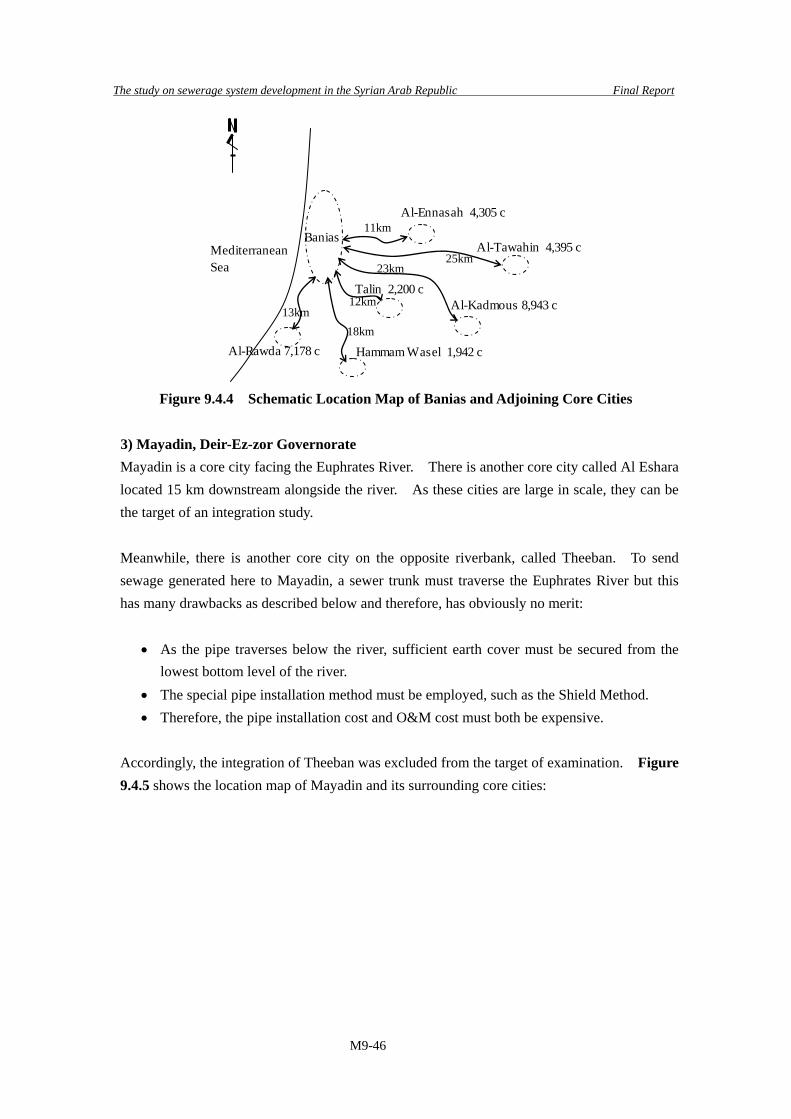
The study on sewerage system development in the Syrian Arab Republic Final Report
M9-46
Banias11km
Al-Tawahin 4,395 cMediterraneanSea
Al-Kadmous 8,943 c
Al-Ennasah 4,305 c
Hammam Wasel 1,942 c
Talin 2,200 c
Al-Rawda 7,178 c
25km
12km
23km
18km13km
Figure 9.4.4 Schematic Location Map of Banias and Adjoining Core Cities
3) Mayadin, Deir-Ez-zor Governorate Mayadin is a core city facing the Euphrates River. There is another core city called Al Eshara located 15 km downstream alongside the river. As these cities are large in scale, they can be the target of an integration study. Meanwhile, there is another core city on the opposite riverbank, called Theeban. To send sewage generated here to Mayadin, a sewer trunk must traverse the Euphrates River but this has many drawbacks as described below and therefore, has obviously no merit:
• As the pipe traverses below the river, sufficient earth cover must be secured from the
lowest bottom level of the river. • The special pipe installation method must be employed, such as the Shield Method. • Therefore, the pipe installation cost and O&M cost must both be expensive.
Accordingly, the integration of Theeban was excluded from the target of examination. Figure 9.4.5 shows the location map of Mayadin and its surrounding core cities:
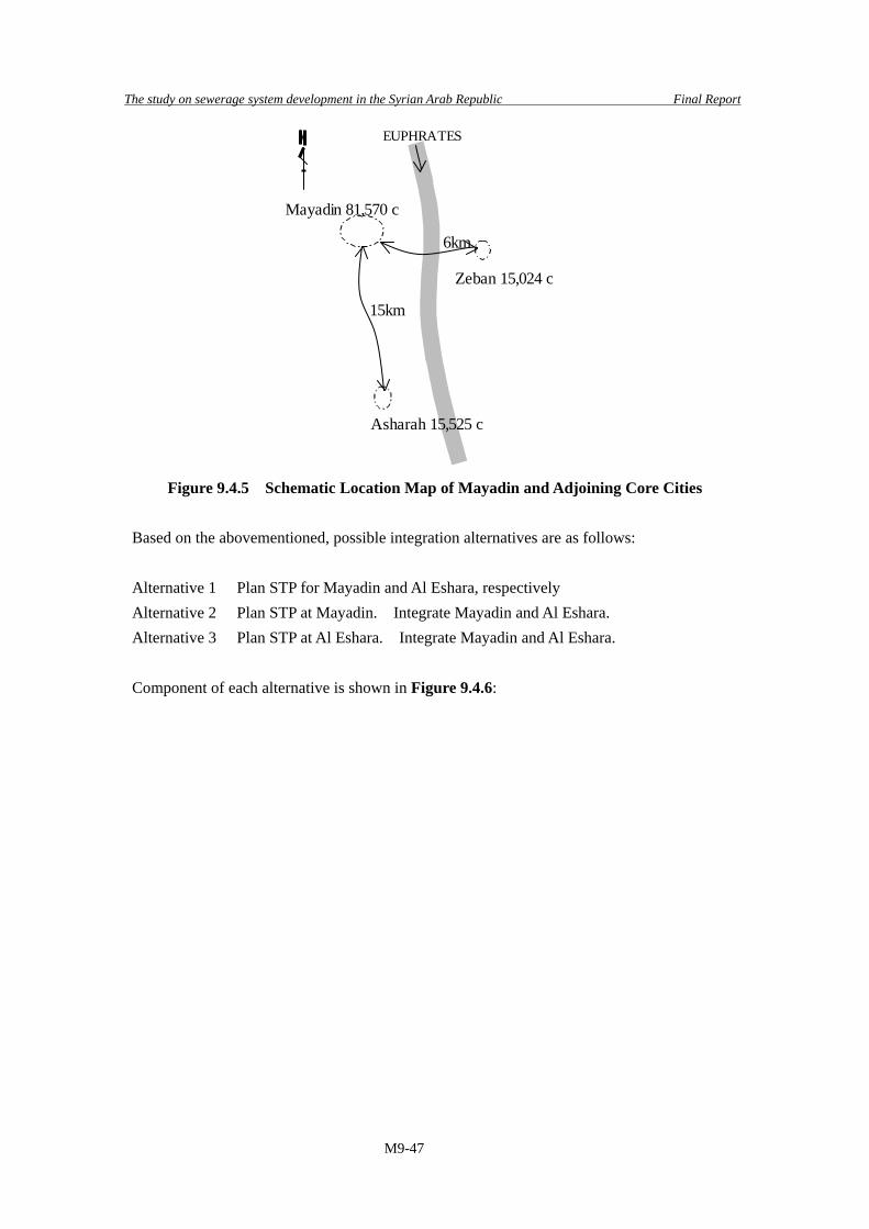
The study on sewerage system development in the Syrian Arab Republic Final Report
M9-47
Zeban 15,024 c
15km
Mayadin 81,570 c
6km
EUPHRATES
Asharah 15,525 c
Figure 9.4.5 Schematic Location Map of Mayadin and Adjoining Core Cities
Based on the abovementioned, possible integration alternatives are as follows:
Alternative 1 Plan STP for Mayadin and Al Eshara, respectively Alternative 2 Plan STP at Mayadin. Integrate Mayadin and Al Eshara. Alternative 3 Plan STP at Al Eshara. Integrate Mayadin and Al Eshara.
Component of each alternative is shown in Figure 9.4.6:

The study on sewerage system development in the Syrian Arab Republic Final Report
M9-48
STP
P
Mayadinand adjoining settlement
Asharahand adjoining settlement
STP
Mayadinand adjoining settlement
Asharahand adjoining settlement
STP
Mayadinand adjoining settlement
Asharahand adjoining settlement
STP
P
Alternative 1 Alternative 2 Alternative 3
Figure 9.4.6 Component of each Alternative As a result of the economical comparison of alternatives, Alternative 2, the planned STP in Mayadin demonstrates a larger sewage flow. Refer to Table 9.4.4. Further, compared with Alternative 3, Alternative 2 has more merit in terms of the antecedent project investment restriction, since there is no need for a long truck sewer to transmit sewage to Al-Eshara in the early stage of the project. Accordingly, sewerage development in Al-Eshara and its surrounding communities is not urgently called for, and can be scheduled to cope with the progress of urbanization and river water pollution.
Table 9.4.4 Economical Comparison on Alternatives
Alternatives Main Components Cost($) Ratio STP at Mayadin STP at Al-Eshara Trunk Sewer
Alternative 1
Sewerage network on adjoining settlements of core city
30,213,754 1.06
STP at Mayadin PS & Trunk Sewer
Alternative 2
Sewerage network on adjoining settlements of core city
28,526,515 1.0
STP at Mayadin STP at Al-Eshara PS & Trunk Sewer
Alternative 3
Sewerage network on adjoining settlements of core city
31,903,490 1.12
Note) As to detailed cost estimation, refer to Volume III, Supporting Report, Part I Master Plan, Appendix 9.6.
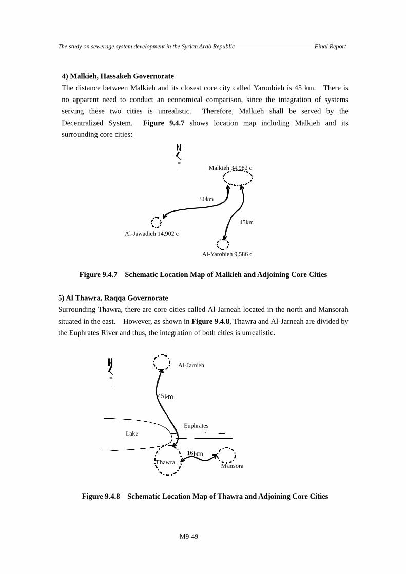
The study on sewerage system development in the Syrian Arab Republic Final Report
M9-49
4) Malkieh, Hassakeh Governorate The distance between Malkieh and its closest core city called Yaroubieh is 45 km. There is no apparent need to conduct an economical comparison, since the integration of systems serving these two cities is unrealistic. Therefore, Malkieh shall be served by the Decentralized System. Figure 9.4.7 shows location map including Malkieh and its surrounding core cities:
Figure 9.4.7 Schematic Location Map of Malkieh and Adjoining Core Cities
5) Al Thawra, Raqqa Governorate Surrounding Thawra, there are core cities called Al-Jarneah located in the north and Mansorah situated in the east. However, as shown in Figure 9.4.8, Thawra and Al-Jarneah are divided by the Euphrates River and thus, the integration of both cities is unrealistic.
Figure 9.4.8 Schematic Location Map of Thawra and Adjoining Core Cities
Al-Yarobieh 9,586 c
Al-Jawadieh 14,902 c
Malkieh 34,982 c
50km
45km
Thawra
Al-Jarnieh
Lake
45km
16km
M ansora
Euphraties RiverEuphrates

The study on sewerage system development in the Syrian Arab Republic Final Report
M9-50
Thawra
SafsafeMansorah Hamarn
Abe Kabe’ee
EUPHRATESLAKE
mountain area Thawra District
Study area for Macro PlanHounayada
Figure 9.4.9 Schematic Location Map of Communities in Thawra Sub-district
Refer to Figure 9.4.9 above. Status of Thawra City and communities located nearby is as follows:
1) Thawra city is situated on a hilly area facing Asad Lake. According to the Census conducted in 2004, the population here is about 70,000, making Thawra city the second biggest city in the Raqqa Governorate. To cope with rapid population growth, a city plan was designed to expand the urban area boundary.
2) Al Safsafeh is comprised of Safsafeh-Tahtany located on the terrace of the Euphrates River and Safsafeh-Foqany situated in the hilly area. Human excreta generated here are treated by Pit Latrine constructed by the respective households. No sewer network has been installed. Throughout the community, housing density is rather weak.
3) Al Hounayada is situated on the terrace of the Euphrates River. Human excreta generated here are treated by Pit Latrine constructed by the respective households. No sewer network has been installed as well. Housing density is likewise weak.
4) Located along the Euphrates River, Mansorah has an existing sewer network and STP. 5) Hamarn is located also on the terrace of the Euphrates River. Human excreta generated
here are treated by Pit Latrine constructed by the respective households. No sewer network has been installed. Housing density is also rather weak.
6) Abe Kabe’ee Gharbe shares the same situation as Hamarn.
Figure 9.4.10 shows the existing sewerage system in this area.

The study on sewerage system development in the Syrian Arab Republic Final Report
M9-51
Thawra
SafsafehMansourah
HamarnAbe Kabe’ee
EUPHRATESLAKE
reed beds
STP
Hounayada
Note; Sewerage Network; Pit Laterine
Figure 9.4.10 Existing Sewerage System in Thawra
Among the six communities described above, Thawra and Monsorah are considered large-scale cities with populations exceeding 50,000. Thus, scale-merit by integration can be expected. Remaining communities were excluded from the scope of the integration examination as they are served by Pit Latrine.
Although there are five existing small-scale STPs in Mansorah, STP operations have been
suspended in three of these facilities due to the lack of proper O&M activities. Integration examination is carried out in the design of two alternatives: Alternative 1 STP is planned for Mansorah and Thawra, respectively Alternative 2 Mansorah and Thawra will have integrated systems. STP is planned for Mansorah As to the composition of each alternative, refer to Figure 9.4.11 to 9.4.12.
Thawra
MansorahSafsafeh Hamam
Abe Kabe’ee
EUPHRATES
LAKE
T
Mansorah Area
THounayada
Figure 9.4.11 Composition of Alternative 1
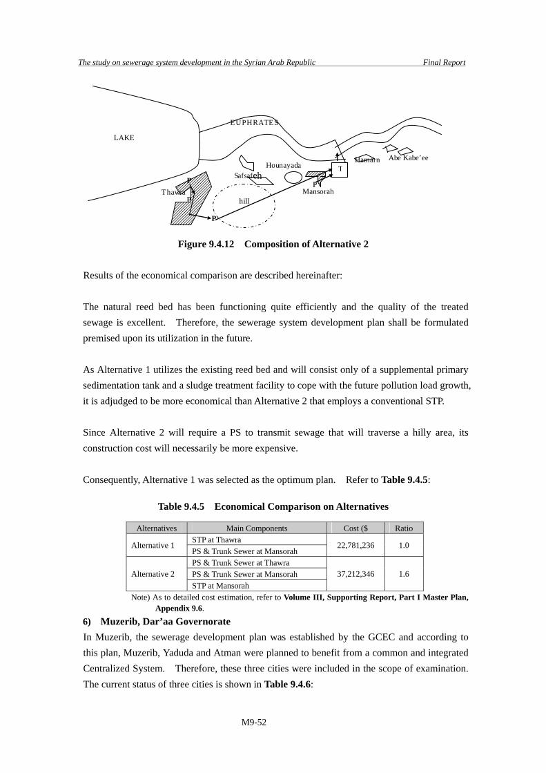
The study on sewerage system development in the Syrian Arab Republic Final Report
M9-52
Abe Kabe’ee
EUPHRATES
LAKE
Thawra
SafsafehMansorah
Hamarn
PT
P
hillP
P
Hounayada
Figure 9.4.12 Composition of Alternative 2
Results of the economical comparison are described hereinafter: The natural reed bed has been functioning quite efficiently and the quality of the treated sewage is excellent. Therefore, the sewerage system development plan shall be formulated premised upon its utilization in the future. As Alternative 1 utilizes the existing reed bed and will consist only of a supplemental primary sedimentation tank and a sludge treatment facility to cope with the future pollution load growth, it is adjudged to be more economical than Alternative 2 that employs a conventional STP. Since Alternative 2 will require a PS to transmit sewage that will traverse a hilly area, its construction cost will necessarily be more expensive. Consequently, Alternative 1 was selected as the optimum plan. Refer to Table 9.4.5:
Table 9.4.5 Economical Comparison on Alternatives
Alternatives Main Components Cost ($ Ratio STP at Thawra
Alternative 1 PS & Trunk Sewer at Mansorah
22,781,236 1.0
PS & Trunk Sewer at Thawra PS & Trunk Sewer at Mansorah Alternative 2 STP at Mansorah
37,212,346 1.6
Note) As to detailed cost estimation, refer to Volume III, Supporting Report, Part I Master Plan, Appendix 9.6.
6) Muzerib, Dar’aa Governorate In Muzerib, the sewerage development plan was established by the GCEC and according to this plan, Muzerib, Yaduda and Atman were planned to benefit from a common and integrated Centralized System. Therefore, these three cities were included in the scope of examination. The current status of three cities is shown in Table 9.4.6:

The study on sewerage system development in the Syrian Arab Republic Final Report
M9-53
Table 9.4.6 Current Status of Cities in Scope of Examination
Name of City Current Status Muzerib Has the largest population.
Sewer network has been developed already and raw sewage is discharged into channel nearby called Wadi Al Dhahab.
Yaduda Located 6 km upstream of Muzerib, it has second largest population. Sewer network has been developed already and raw sewage is discharged into Wadi Al Dhahab as well.
Atman Located 4 km upstream of Muzerib, it has the smallest population. Sewer network has not been developed yet.
As these three cities are densely inhabited, service by a Centralized System seems advantageous. However, Atman was judged to be more efficiently served by a Decentralized System due to the following circumstances:
• Since the sewer network has not yet been installed,, the development is estimated to
take a longer perod of time. • No contamination of public water bodes has been reported yet. • As the topography between Atman and Yaduda is flat, PS is necessary to send sewage
generated in Atman to Yaduda. • Raw sewage generated in Atman is discharged through a channel nearby that differs
from that n Muzerib and Yaduda. • Severe opposition might arise from residents near to the STP construction site who are
against the treatment of sewage coming from other communities. Considering the abovementioned conditions, alternative study presenting two alternatives has been conducted and they are as follows:
Alternative 1 Plan separate STPs for Muzerib, Yaduda and Atman, respectively Alternative 2 Plan an integrated system for Muzerib and Yaduda and another Decentralized
system for Atman. The major components of each case are as follows:
Alternative 1
• Plan an STP with a capacity of 1,700 m3/d located near the discharge point of Muzerib with a population of 17,180.
• Plan an STP with a capacity of 1,700 m3/d located near the discharge point of Yaduda with a population of 17,200.
• Plan an STP with a capacity of 1,500 m3/d located near the discharge point of Atman with a population of 15,200.

The study on sewerage system development in the Syrian Arab Republic Final Report
M9-54
Alternative 2 • Plan a PS with a capacity of 2.386 m3/sec located near the discharge point of Muzerib
with a population of 17,200 to pump sewage to STP 4.5 km away. Diameter of the force main is 200 mm.
• Send sewage generated in Yaduda with total population of 17,200 including refugees numbering 5,000 to the STP by gravity. Pipe length is 2.0 km and diameter is 300 mm.
• Plan an STP with a capacity of 3,400 m3/d located at the intermediate point between Muzerib and Yaduda.
• Plan an STP with a capacity of 1,500 m3/d in Atman.
The results of the economical comparison are shown in Table 9.4.7.
Table 9.4.7 Economical Comparison on Alternatives
Alternatives Main Components Cost ($) Ratio STP at Muzerib STP at Yaduda
Alternative 1
STP at Atman 15,512,087
1.00
PS at Muzerib Trunk Sewer from Muzerib to STPTrunk Sewer from Yaduda to STP STP at Muzerib&Yaduda
Alternative 2
STP at Atman
14,036,999
0.90
Note) As to detailed cost estimation, refer to Volume III, Supporting Report, Part I Master Plan, Appendix 9.6.
As shown on this Table, the total project cost of Case 2 that represents the integration case of Muzerib and Yaduda is 10 % cheaper than the cost of Case 1. As the cost difference is small, Case 1 with the advantage of phased implementation is feasible but Case 2 was the one that was finally selected owing to the following considerations:
• Adjustments in anticipation of project implementation are on-going between Muzerib,
Yaduda and Dar’aa Governorates. • Sewerage system development in Muzerib and Yaduda is urgent. • STP O&M engineers cannot be easily hired.
Figure 9.4.13 shows the schematic map of the sewerage system.

The study on sewerage system development in the Syrian Arab Republic Final Report
M9-55
STP
Muzerib
Yaduda
Atman
●
●
●
●
●
●
●
●
●
●
●
●
●
P
STP▽GL 454
▽GL 462
▽GL 454
▽GL 471
▽GL 435
▽GL 440
▽GL 466
●
▽GL 520
▽GL 510
Wadi Al Dhahab
Wellspring
Fig 9.4.13 Schematic Map of Sewerage System of Muzerib
7) Zabadani, Rural Damascus Governorate As to Zabadani, the Pre-Feasibility Study was prepared by the EIB. According to this study, the seven communities of Zabadani, Bludan, Buqqin, Madaya, Ain Hour, Rawdah and Hosh Bujd were planned to be served by one Centralized System. Based on the field survey, the Study Team classified these communities into two categories, namely communities to be served by the Centralized System and those to be served by the Decentralized System.
a) Zabadani, Bludan, Buqqin, Madaya
These four communities are located at the central area of Zabadani. As housing here is dense, service by Centralized System appears advantageous. Further, since these communities are located close to each other, they shall be inevitably served by an integrated system.
b) Ain Hour This community is located 5 km away from Zabadani in the north. In consideration of the following circumstances, the Decentralized System was employed for this community: • The residential area is served by two existing sewer network systems divided by a
small creek that flows down the middle of the community. Collected raw wastewater has been discharged into the said creek and has been contributing to water contamination.
It should be noted further that the existing sewer network has deteriorated badly due to aging. Pipe breakage was also reported. As concrete pipes are supposed to be installed, these will be replaced by more reliable pipe materials like PVC and PE as indicated in

The study on sewerage system development in the Syrian Arab Republic Final Report
M9-56
Chapter 5, p5-48, Table 5.2.33. c) Rawdah
Rawdaw is a community located in a western hilly area with a population of 4,536. As the average housing interval is 50 m approximately, the Decentralized System is applicable. However, since Rawdah is located far from Zabadani, Bludan, Buqqin and Madaya, integration with these communities is not advantageous.
d) Hosh Bujd Although Hosh Bujd is a small-scaled community located at the end of western hilly area, it has been served by an existing sewer network and collected wastewater has been discharged into small creeks through two discharge points. Since efforts are ongoing to conserve the Zabadani area as a tourist resource, a thorough pollution control measure should be undertaken. Therefore, the Study Team proposed the installation of a Decentralized System for the purpose of this community.
As abovementioned, the classification is as follows:
• Zabadani, Bludan, Buqqin and Madaya = Integrated service by Centralized System • Rawdah, Ain Hour and Hosh Bujd = Decentralized System
Figure 9.4.14 shows schematic map of sewerage system.
Fig 9.4.14 Schematic Map of Sewerage System of Zabadani The examination results of the Macro Plan are shown in Figure 9.4.15 to Figure 9.4.21.
AinHour
Bloudan
Zabadani
Bukei
Madaya
Rawdah
HoshBajet
BaradaRiver
BaradaSpring
T
SmallstreamL=6km
N
Bukein
Bujed
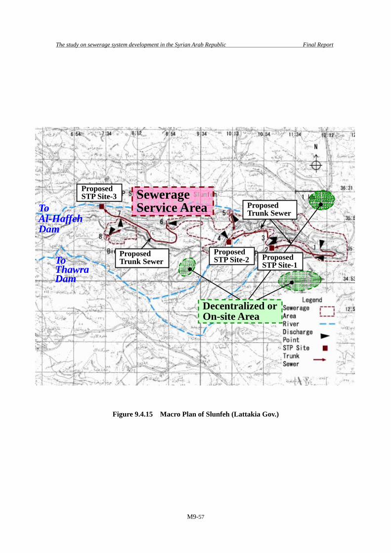
The study on sewerage system development in the Syrian Arab Republic Final Report
M9-57
Figure 9.4.15 Macro Plan of Slunfeh (Lattakia Gov.)
Sewerage Service Area
Decentralized or On-site Area
Proposed Trunk Sewer
ProposedSTP Site-2
Proposed Trunk Sewer
Proposed STP Site-1
Proposed STP Site-3
To Al-Haffeh Dam
To Thawra Dam

The study on sewerage system development in the Syrian Arab Republic Final Report
M9-58
Figure 9.4.16 Macro Plan of Banias (Tartous Gov.)
Sewerage Service Area
Decentralized or On-site ServiceArea
Proposed STP Site
Proposed Trunk Sewer
Mediterranean Sea

The study on sewerage system development in the Syrian Arab Republic Final Report
M9-59
Figure 9.4.17 Macro Plan of Mayadin(Deir-Ez-Zor Gov.)
Sewerage Service Area
On-site Service Area
Proposed STP Site
Proposed Trunk Sewer
Euphrates River
Proposed Pumping StationSite
SewerageService Area

The study on sewerage system development in the Syrian Arab Republic Final Report
M9-60
Figure 9.4.18 Macro Plan of Malkieh (Hassakeh Gov.)
Sewerage Service Area
Proposed STP Site
Proposed Trunk Sewer
Dam
Decentralized or On-Site Service Area

The study on sewerage system development in the Syrian Arab Republic Final Report
M9-61
Figure 9.4.19 Macro Plan of Thawra (Raqqa Gov.)
Sewerage Service Area
On-site ServiceArea
Proposed STP Site
Proposed Trunk Sewer
Al Assad Lake
Reed Bed
Euphrates River

The study on sewerage system development in the Syrian Arab Republic Final Report
M9-62
Figure 9.4.20 Macro Plan of Muzerib (Dar’aa Gov.)
Sewerage Service Area
On-site Service Area
Proposed Trunk Sewer
Proposed STP Site
Sewerage Service Area
Decentralized Service Area
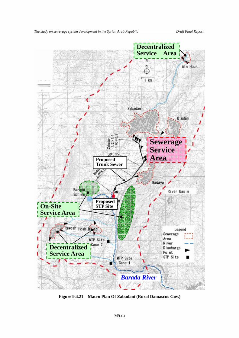
The study on sewerage system development in the Syrian Arab Republic Draft Final Report
M9-63
Figure 9.4.21 Macro Plan Of Zabadani (Rural Damascus Gov.)
Sewerage Service Area
Decentralized Service Area
Proposed STP Site
Proposed Trunk Sewer
Barada River
Decentralized Service Area
On-Site Service Area
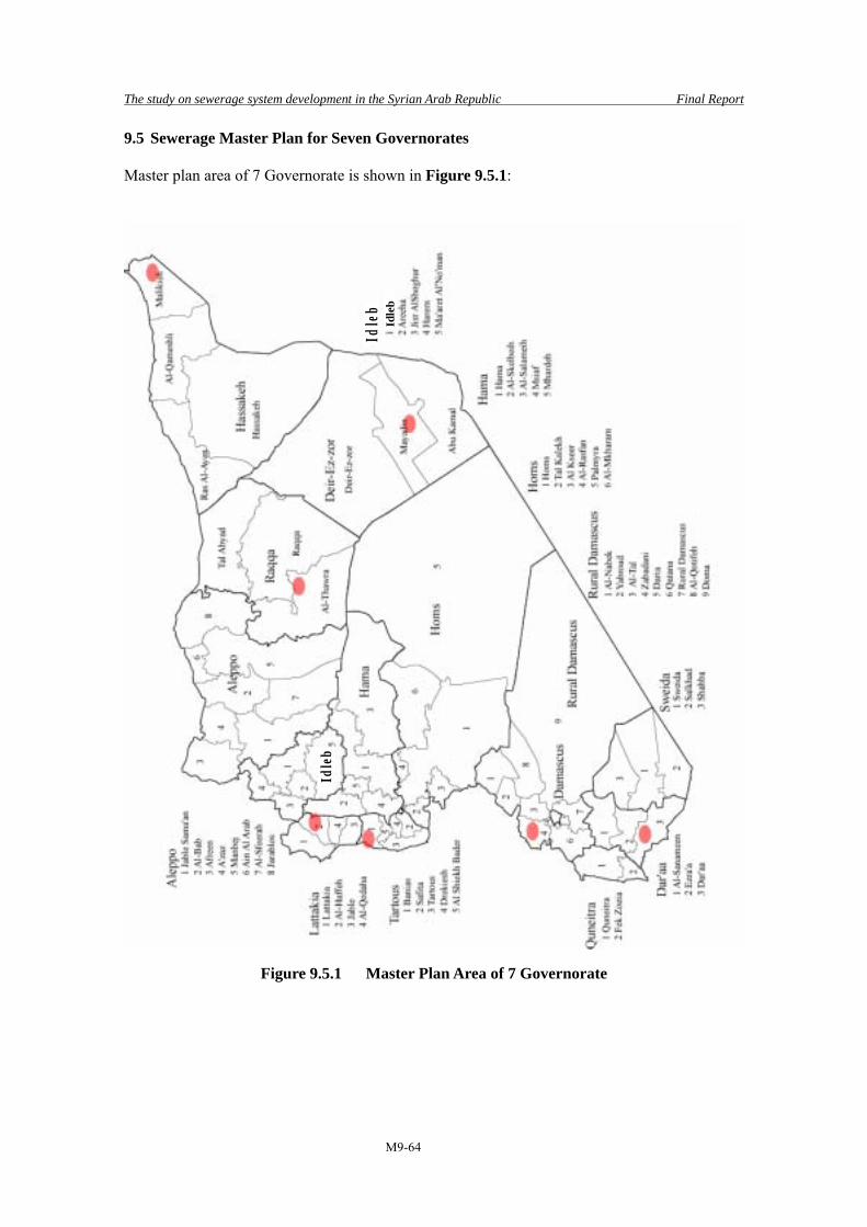
The study on sewerage system development in the Syrian Arab Republic Final Report
M9-64
9.5 Sewerage Master Plan for Seven Governorates
Master plan area of 7 Governorate is shown in Figure 9.5.1:
Figure 9.5.1 Master Plan Area of 7 Governorate
Idle
b
Idle
bId
leb

The study on sewerage system development in the Syrian Arab Republic Final Report
M9-65
9.5.1 Slunfeh, Lattakia Governorate
(1) Study Area Lattakia Governorate is located along Mediterranean Sea and is a center of industry and tourism. In the eastern side of the governorate, the area is steep mountainous and there are several villages near the top of mountains. Total population of the governorate is about 900 thousands. There are 4 districts in Lattakia Governorate, namely, Lattakia, Jable, Al-Haffeh, and Al-Qedaha. Slunfeh, which is the target city of the Master Plan, is located in Al-Haffeh District and the District has 5 sub-districts such as Al-Haffeh, Slunfeh, Ain Al-Tineh, Kansaba, and Al-Mzer’aa. Population of Slunfeh Sub-district is about 20,000 and population of Slunfeh occupies about 10 % of the sub-district population, about 1,900. There are 25 communities in the Slunfeh Sub-District like Slunfeh and the largest community is Salma of which population is about 2,100 and the Slunfeh is the second largest community in the sub-district.
Although Biereen which locates in west of Slunfeh is not considered in the Macro Plan, the Biereen is treated as part of the study area since the Biereen is under administrative jurisdiction of Slunfeh. Slunfeh is located in east of and at 38 km away from Lattakia. Because of comfortable temperature in summer season, many tourists visit Slunfeh. During the high season of tourism, volume of wastewater reaches 5 times of one in winter season.
Slunfeh is located at the most upstream of the river basin. Wastewater of Slunfeh is collected by sewer pipelines and discharged to V-shaped valley. According to the results of investigation at winter season, there was no wastewater flow at the discharge point. It seems all wastewater penetrates into ground because less quantity of wastewater during the winter season. Untreated wastewater will penetrate into ground during flow down in the valley and it may contaminate groundwater which is used as source of water supply. In seaside area in downstream, people depends on spring or well for their drinking water. Therefore, contamination of groundwater is considered as urgent issue and people are eager to have adequate wastewater treatment system in upstream area.
Figure 9.5.2 Master Plan Area in Al-Haffeh District
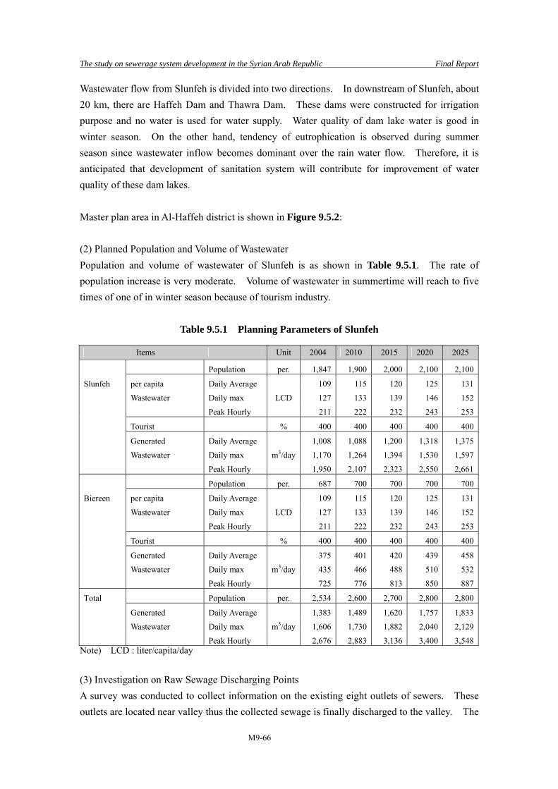
The study on sewerage system development in the Syrian Arab Republic Final Report
M9-66
Wastewater flow from Slunfeh is divided into two directions. In downstream of Slunfeh, about 20 km, there are Haffeh Dam and Thawra Dam. These dams were constructed for irrigation purpose and no water is used for water supply. Water quality of dam lake water is good in winter season. On the other hand, tendency of eutrophication is observed during summer season since wastewater inflow becomes dominant over the rain water flow. Therefore, it is anticipated that development of sanitation system will contribute for improvement of water quality of these dam lakes. Master plan area in Al-Haffeh district is shown in Figure 9.5.2: (2) Planned Population and Volume of Wastewater Population and volume of wastewater of Slunfeh is as shown in Table 9.5.1. The rate of population increase is very moderate. Volume of wastewater in summertime will reach to five times of one of in winter season because of tourism industry.
Table 9.5.1 Planning Parameters of Slunfeh
Items Unit 2004 2010 2015 2020 2025
Population per. 1,847 1,900 2,000 2,100 2,100
Slunfeh per capita Daily Average 109 115 120 125 131
Wastewater Daily max LCD 127 133 139 146 152
Peak Hourly 211 222 232 243 253
Tourist % 400 400 400 400 400
Generated Daily Average 1,008 1,088 1,200 1,318 1,375
Wastewater Daily max m3/day 1,170 1,264 1,394 1,530 1,597
Peak Hourly 1,950 2,107 2,323 2,550 2,661
Population per. 687 700 700 700 700
Biereen per capita Daily Average 109 115 120 125 131
Wastewater Daily max LCD 127 133 139 146 152
Peak Hourly 211 222 232 243 253
Tourist % 400 400 400 400 400
Generated Daily Average 375 401 420 439 458
Wastewater Daily max m3/day 435 466 488 510 532
Peak Hourly 725 776 813 850 887
Total Population per. 2,534 2,600 2,700 2,800 2,800
Generated Daily Average 1,383 1,489 1,620 1,757 1,833
Wastewater Daily max m3/day 1,606 1,730 1,882 2,040 2,129
Peak Hourly 2,676 2,883 3,136 3,400 3,548Note) LCD : liter/capita/day
(3) Investigation on Raw Sewage Discharging Points A survey was conducted to collect information on the existing eight outlets of sewers. These outlets are located near valley thus the collected sewage is finally discharged to the valley. The

The study on sewerage system development in the Syrian Arab Republic Final Report
M9-67
information was provided by the engineers of Slunfesh. The city of Slunfeh is developed at the top of mountain area, the sewage is discharged through the existing outlets of sewers and reached at two different destinations: Haffeh dam or Thawa dam. Table 9.5.2 summarizes the information of outlets including estimated flow rate ratios between those in winter and summer. The average ratio is about 20%, in other words, the sewage would be generated five times higher than those in winter.
Table 9.5.2 Discharge Points in Slunfeh
No Location of Outlet Sewer Diameter
(mm) Final Discharge Point
Flow Rate Ratio (%)
1 Ain Al Bayda 400 Al Thawra Dam 30 2 Jeb Sulaiman 300 Al Thawra Dam 20 3 Al Bareed 400 Al Thawra Dam 25 4 Al Joubeh 400 Al Thawra Dam 20 5 Haret Al Derjeh 300 Al Haffeh Dam 15 6 Hannah Village 400 Al Haffeh Dam 10 7 Biereen (school) 300 Al Haffeh Dam 10
8 Biereen (Al Harah Al Kadimeh) 400 Al Thawra Dam 20
Note) Flow Rate Ratio = Winter/Summer
(4) Selection of STP Site The planning area is divided into two sub-basins. In addition, there are eight raw sewage discharge points being dotted about over 7 km length. Under these circumstances, construction of only one sewage treatment plant to collect all sewage in a centralized manner would not be feasible. It was selected three candidate sites for STPs after due consideration of geographical conditions and site investigations with the officials of the Ministry of Housing and Construction of Slunfeh District. Following issues are considered in the course of selection of the candidates of proposed STP sites: • Sewage effluent from a dischage point can be efficiently collected. • Access road to the proposed site is available. • Enough area is available for STP construction. • There are not many houses around the proposed STP site. Table 9.5.3 gives a summary of the proposed STP sites.
Table 9.5.3 Location of the Proposed STP Sites (Slunfeh)
No Latitude N Longitude E LevelDischargePoint ID
No.
Available Area
Land Cost
Land Owner
Distance from
residential area
1 35°35′31.4″ 36°11′03.1″ 1,000 1, 2 More than 1ha
1,000 SP/m2 Private 200m
2 35°35′41.8″ 36°09′59.7″ 994 3, 4, 5 More than 1ha - Public 50m
3 35°36′11.4″ 36°07′24.4″ 737 6, 7, 8 0.5ha - Public 100m

The study on sewerage system development in the Syrian Arab Republic Final Report
M9-68
(5) Sewage Collection Plan 1) Trunk Sewer Plan It is proposed that the sewage collected by the existing sewers will be conveyed by new gravity trunk sewers from each discharge point to the proposed STP in principal. However the sewage at the discharge point No. 5 and No.8, both are located near the proposed STP, will be conveyed by pumping stations considering following reasons: • Installation of a force main is more economical than a gravity sewer, because the distance
from No.5 discharge point to No.6 discharge point is as much as 2.5km. • No.8 discharge point locates at different basin from No.3 STP. However, a provision of
pump station is more economical than construction of another STP. A sewage flow at each discharge point is approximately 450m3/day, as the total design maximum hourly flow of 3,548m3/day is divided by eight discharge points. The sewer slope can be applicable more than 10 ‰ because the STP sites locate lower than those discharging points. It is possible for 250mm of minimum diameter sewer to cater for the flow form two discharge points as shown in Table 9.5.4.
Table 9.5.4 Design of Trunk Sewer
Flow rate Capacity Diameter Gradient v Q m3/day m3/s m3/s mm ‰ m/s m3/s
900 0.010 0.020 250 10 1.58 0.077
2)Pumping Station Plan Design maximum hourly sewage flow =3,548/8=444 m3/day=0.3 m3/min Pump capacity is recommended to be 0.5m3/min including some allowance. Size of force main is 100mm as calculated bellow.
m....
.D 10001030011434008330
→=××
=
(6) Planning of STP 1) Influent quality and Effluent standard Treated wastewater will be discharged to valley. It finally flows to the two dams through valley distance of 20 to 28 km away from Slunfeh. Reserved water in dams is used for irrigation of fruit trees. Therefore, Effluent Standard would be applied for the discharge to River.
Table 9.5.5 Incoming Sewage Quality and Effluent Standard
Maximum Allowed Limited effluent standard from STP (mg/l) Items
Discharge mode to water-body
/ Condition of re-use BOD SS NH3-N NO3-N T-N T-P
Influent 310 360 74 24 Effluent Standard
Proposed effluent standard ( River)
40 30 5 50

The study on sewerage system development in the Syrian Arab Republic Final Report
M9-69
2) Summary of conditions and proposed facilities The conditions considered for Planning and specifications of proposed facilities are listed in Table 9.5.6
Table 9.5.6 Summary of Conditions and Proposed Facilities
Items Contents Average wastewater (m3/d) 1,833 Hourly max wastewater (m3/d) 3,548 Sludge (kgDS/d) 224 Sludge (m3/d) 2.7 Moisture content (%) 92 No. of STP 3 Treatment method Submerged attached growth
For each STP of capacity 500 m3/d) Grit chamber (No.-w×L) 1-1m×1m Main P (No.-D×power) - Reactor (No.-W×L×H) 2-5.5m×12m×5m Final sedimentation tank 2-5.5m×3m Disinfection channel 1-φ0.9m(manhole) Required land area (ha) Each 0.1
3) Sewage treatment method There are three narrow lands available for STP, each with an area of 0.1 ha. Therefore, 3 small STPs are proposed to be constructed with capacity of 610 m3/d each, collecting sewage from several discharges to three STPs. As the proposed STP is very small, Submerged Attached Growth Method, known as unmanned on-site facility in Japan, is suitable for small stretch of available land. Submerged Attached Method has some favorable features, for example, no need of return activated sludge, sludge, digested slime peeled from bio-film is assumed 30 percent of removed SS because removed VSS would be almost digested and gasified. So disposal of sludge could be carried out using low-budget. This method requires bio-film, generally plastic media, so relatively costly in terms of construction. However, O&M in this process is easy and it does not need the resident engineers, therefore in long run the total cost for this method is cheaper. Moreover, the environmental risk through an unmanned operation is small because of small amount of wastewater. In consequence, Submerged Attached Growth Method has been proposed for this case. 4) Sludge treatment method This sewage treatment method generate small amount of sludge, so in Japan mainly maintenance is carried out once a year. Also, annual rainfall in Slunfeh is 1,000 mm to 1,400 mm, and therefore drying bed is not applicable. Considering these factors, sludge treatment

The study on sewerage system development in the Syrian Arab Republic Final Report
M9-70
would be neglected for this case, and generated sludge is proposed to be conveyed to Lattakia STP by tanker. 5) Special Consideration on facility Planning • All facilities are set up on the condition of unmanned operation, but by patrol duty, so
there is no sludge treatment facility or administration building. • To achieve effective O&M, following periodic maintenance activities would be required
necessarily: a) Adjustment of aeration device, Two times a year, once before and once at end of summer b) Water analysis of discharged sewage once a month c) Checking and removal of the coarse material remaining at screen basket, and supply of
solid chlorine, once a week. d) Sludge, settled bio-slim peeled from bio-film, would be collected at the bottom of
settling tank and collected by the tanker with vacuum device and conveyed to Lattakia STP.
Master plan of Slunfeh is shown in Figure 9.5.3:

The study on sewerage system development in the Syrian Arab Republic Final Report
M9-71
Figure 9.5.3 Master Plan of Slunfeh

The study on sewerage system development in the Syrian Arab Republic Final Report
M9-72
9.5.2 Banias, Tartous Governorate
(1) Study Area Tartous Governorate is located along the Mediterranean Sea. In the governorate, wastewater is discharged into the sea without any treatment through 60 discharge points. These discharges cause sea water pollution. Total population in the governorate is about 700 thousand. Tartous Governorate consists of five districts such as Tartous, Banias, Safita, Drekiesh, and Al-Shiekh Bader. Banias district has 7 sub-districts and they are Banias, Al-Rawda, Hemmam Wasel, Al-Eennasah, Al-Kadomous, Talin, and Al-Tawahin. Total population of the Banias District is about 95,000 and about half of the total population, 42,000 people lives in Banias. There are 36 communities in the Banias Sub-District like Banias. Population of the second largest city is about 5,000 and the other communities have lesser population and these small scale communities are scattered in mountainous area in eastern side.
Although these three areas, Tero, Khrbet Snasel, and Boston Al-Najo, were not included in the Macro Plan, these areas will be treated as part of the study area from aspects listed below.
• Elevation of these three areas are higher and wastewater can be transmitted to Banias easily
• Roads are available to accommodate sewer pipelines • Engineers in Banias had already agreed to accept wastewater from these three areas
Master plan area in Banias district is shown in Figure 9.5.4: Banias is the oceanfront city and wastewater from Banias is discharged into the sea without treatment. This area is tourist spot and many tourists visit Banias in summer vacation season. Water quality of the sea is deteriorated because of discharged domestic wastewater. Water quality will be drastically improved if adequate wastewater treatment system was introduced in this area. Improvement of sea water quality will contribute to not only for tourism industry but also for domestic living conditions. Sewage Development Plan of Banias was once prepared by Egyptian Consultant as Pre-Investment Study in March 2005. Based on “MED POL (Mediterranean Marine Pollution Monitoring and Research Program)”, the sewage development plan will be implemented using
Figure 9.5.4 Master Plan Area in Banias District
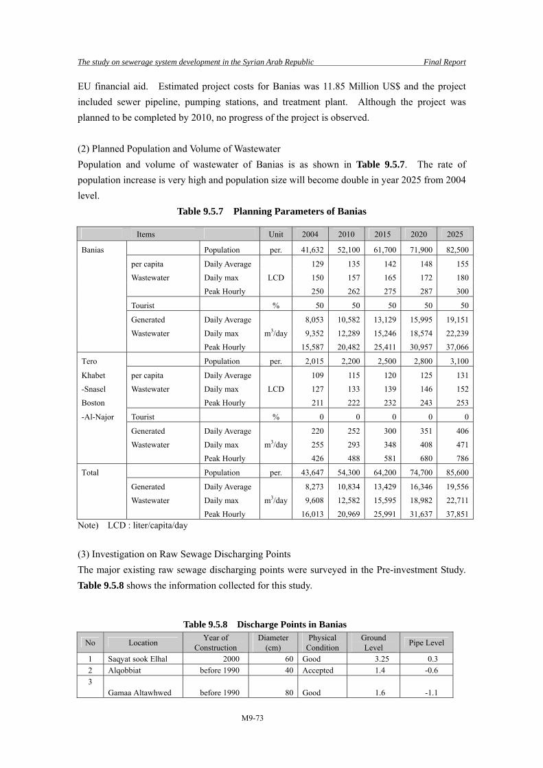
The study on sewerage system development in the Syrian Arab Republic Final Report
M9-73
EU financial aid. Estimated project costs for Banias was 11.85 Million US$ and the project included sewer pipeline, pumping stations, and treatment plant. Although the project was planned to be completed by 2010, no progress of the project is observed. (2) Planned Population and Volume of Wastewater Population and volume of wastewater of Banias is as shown in Table 9.5.7. The rate of population increase is very high and population size will become double in year 2025 from 2004 level.
Table 9.5.7 Planning Parameters of Banias
Items Unit 2004 2010 2015 2020 2025
Banias Population per. 41,632 52,100 61,700 71,900 82,500
per capita Daily Average 129 135 142 148 155
Wastewater Daily max LCD 150 157 165 172 180
Peak Hourly 250 262 275 287 300
Tourist % 50 50 50 50 50
Generated Daily Average 8,053 10,582 13,129 15,995 19,151
Wastewater Daily max m3/day 9,352 12,289 15,246 18,574 22,239
Peak Hourly 15,587 20,482 25,411 30,957 37,066
Tero Population per. 2,015 2,200 2,500 2,800 3,100
Khabet per capita Daily Average 109 115 120 125 131
-Snasel Wastewater Daily max LCD 127 133 139 146 152
Boston Peak Hourly 211 222 232 243 253
-Al-Najor Tourist % 0 0 0 0 0
Generated Daily Average 220 252 300 351 406
Wastewater Daily max m3/day 255 293 348 408 471
Peak Hourly 426 488 581 680 786
Total Population per. 43,647 54,300 64,200 74,700 85,600
Generated Daily Average 8,273 10,834 13,429 16,346 19,556
Wastewater Daily max m3/day 9,608 12,582 15,595 18,982 22,711
Peak Hourly 16,013 20,969 25,991 31,637 37,851Note) LCD : liter/capita/day (3) Investigation on Raw Sewage Discharging Points The major existing raw sewage discharging points were surveyed in the Pre-investment Study. Table 9.5.8 shows the information collected for this study.
Table 9.5.8 Discharge Points in Banias
No Location Year of Construction
Diameter (cm)
Physical Condition
Ground Level Pipe Level
1 Saqyat sook Elhal 2000 60 Good 3.25 0.3 2 Alqobbiat before 1990 40 Accepted 1.4 -0.6 3 Gamaa Altawhwed before 1990 80 Good 1.6 -1.1
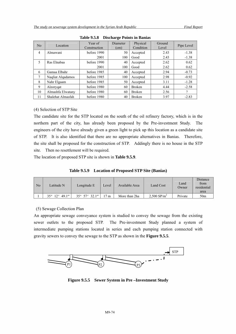
The study on sewerage system development in the Syrian Arab Republic Final Report
M9-74
Table 9.5.8 Discharge Points in Banias
No Location Year of Construction
Diameter (cm)
Physical Condition
Ground Level Pipe Level
4 Almawani before 1990 50 Accepted 2.43 -1.38 2001 100 Good 2.43 -1.38
5 Ras Elnabaa before 1990 40 Accepted 2.62 0.62 2001 100 Good 2.62 0.62
6 Gamaa Elbahr before 1985 40 Accepted 2.94 -0.73 7 Naqliat Alqadamos before 1985 100 Accepted 2.98 -0.92 8 Nahr Elgaam before 1985 50 Accepted 3.11 -1.28 9 Alzoryqat before 1980 60 Broken 4.44 -2.58 10 Almashfa Elwatany before 1980 60 Broken 2.56 ? 11 Shalehat Almasfah before 1980 40 Broken 3.97 -2.83
(4) Selection of STP Site The candidate site for the STP located on the south of the oil refinery factory, which is in the northern part of the city, has already been proposed by the Pre-investment Study. The engineers of the city have already given a green light to pick up this location as a candidate site of STP. It is also identified that there are no appropriate alternatives in Banias. Therefore, the site shall be proposed for the construction of STP. Addingly there is no house in the STP site. Then no resettlement will be required. The location of proposed STP site is shown in Table 9.5.9.
Table 9.5.9 Location of Proposed STP Site (Banias)
No Latitude N Longitude E Level Available Area Land Cost Land Owner
Distance from
residential area
1 35°12′49.1″ 35°57′32.1″ 17 m More than 2ha 2,500 SP/m2 Private 50m
(5) Sewage Collection Plan An appropriate sewage conveyance system is studied to convey the sewage from the existing sewer outlets to the proposed STP. The Pre-investment Study planned a system of intermediate pumping stations located in series and each pumping station connected with gravity sewers to convey the sewage to the STP as shown in the Figure 9.5.5.
Figure 9.5.5 Sewer System in Pre –Investment Study
P1 P2 P3
STP
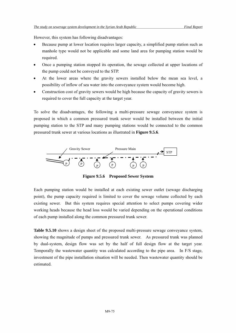
The study on sewerage system development in the Syrian Arab Republic Final Report
M9-75
However, this system has following disadvantages: • Because pump at lower location requires larger capacity, a simplified pump station such as
manhole type would not be applicable and some land area for pumping station would be required.
• Once a pumping station stopped its operation, the sewage collected at upper locations of the pump could not be conveyed to the STP.
• At the lower areas where the gravity sewers installed below the mean sea level, a possibility of inflow of sea water into the conveyance system would become high.
• Construction cost of gravity sewers would be high because the capacity of gravity sewers is required to cover the full capacity at the target year.
To solve the disadvantages, the following a multi-pressure sewage conveyance system is proposed in which a common pressured trunk sewer would be installed between the initial pumping station to the STP and many pumping stations would be connected to the common pressured trunk sewer at various locations as illustrated in Figure 9.5.6.
Figure 9.5.6 Proposed Sewer System Each pumping station would be installed at each existing sewer outlet (sewage discharging point), the pump capacity required is limited to cover the sewage volume collected by each existing sewer. But this system requires special attention to select pumps covering wider working heads because the head loss would be varied depending on the operational conditions of each pump installed along the common pressured trunk sewer. Table 9.5.10 shows a design sheet of the proposed multi-pressure sewage conveyance system, showing the magnitude of pumps and pressured trunk sewer. As pressured trunk was planned by dual-system, design flow was set by the half of full design flow at the target year. Temporally the wastewater quantity was calculated according to the pipe area. In F/S stage, investment of the pipe installation situation will be needed. Then wastewater quantity should be estimated.
P P P
STP
P P P
Gravity Sewer Pressure Main

The study on sewerage system development in the Syrian Arab Republic Final Report
M9-76
Table 9.5.10 Design of Trunk Sewer
No Location A (m2)
Q (m3/s)
Q (m3/min)
1/2Q (m3/min)
Pump(m3/min)
Pipe (m3/min)
Calc.Dia(mm)
Dia (mm)
L (m)
Total Head(m)
Kw
1 Saqyat sook Elhal 0.28 0.027 1.6 0.8 326 2 Alqobbiat 0.13 0.012 0.7 0.4 255 3 Gamaa Altawhwed 0.50 0.048 2.9 1.4 3.0 3.0 0.25 250 139 30.7 28.74 Almawani 0.20 0.019 1.1 0.6 0.79 0.075 4.5 2.2 3.0 6.0 0.36 300 548 26.1 24.55 Ras Elnabaa 0.13 0.012 0.7 0.4 0.79 0.075 4.5 2.2 3.0 9.0 0.44 400 675 19.2 18.06 Gamaa Elbahr 0.13 0.012 0.7 0.4 1.0 10.0 0.46 400 95 17.4 5.47 Naqliat Alqadamos 0.79 0.075 4.5 2.2 3.0 13.0 0.53 500 362 17.1 16.08 Nahr Elgaam 0.20 0.019 1.1 0.6 1.0 14.0 0.55 500 871 16.4 5.19 Alzoryqat 0.28 0.027 1.6 0.8 1.0 15.0 0.56 500 580 14.6 4.6
10 Almashfa Elwatany 0.28 0.027 1.6 0.8 1.0 16.0 0.58 600 639 11.7 3.611 Shalehat Almasfah 0.13 0.012 0.7 0.4 1.0 17.0 0.60 600 1672 11.4 3.6 Total 4.60 0.438 17.0
As to detailed economical comparison, refer to Volume III, Appendix 9.5.
(6) Planning of STP
1) Influent quality and Effluent standard Treated wastewater in this case will be discharged to sea through storm channel.
Table 9.5.11 Incoming Sewage Quality and Effluent Standard in Banias
Maximum Allowed Limited effluent standard from STP (mg/l) Items
Discharge mode to water-body
/ Condition of re-use BOD SS NH3-N NO3-N Coliform Influent 310 360 Effluent Standard
Proposed effluent standard (Sea)
60 60 10 50 5000
MPN/100ml
2) Summary of conditions and proposed facilities Planning conditions and dimensions of proposed facilities based on the design results are listed in Table 9.5.12.

The study on sewerage system development in the Syrian Arab Republic Final Report
M9-77
Table 9.5.12 Summary of Conditions and Proposed Facilities
Items Contents
Average wastewater (m3/d) 19,556 Hourly max wastewater (m3/d) 37,851 Sludge (kgDS/d) 4,401 Sludge (m3/d) 22.0 Moisture content (%) 80
Treatment method OD +Gravity Thickener + Mechanical dewatering
Grit chamber (No.-w×L) 2-1.5m×7m Main P (No.-D×power) - Reactor (No.-W×L×H) 12-4.5m×140m×3.0m(high rate) Final sedimentation tank 8-φ18m Disinfection channel 2-2m×24×2.1m Gravity Sludge Thickener 2-5.0m×5.0m Mechanical Sludge Dehydrator 2-2,201 kg DS/d Required land area (ha) 5.1
3)Sewage treatment method Conventional Activated Sludge method is applicable due to the effluent standard though, primary settling tank of Conventional Activated Sludge method generates offensive odor. As STP land will be in the future urban district, Conventional Extended Aeration or OD that does not require primary settling tank, is better than conventional activated sludge method. Based on the result of comparison, OD is better than Conventional Extended Aeration considering the total cost including O&M cost and others. Hence, OD which requires easy operation among them, has been proposed.
Table9.5.13 Comparison of Treatment Process in Banias
Items OD Conventional
extended aeration Conventional
Activated Sludge Possibility of layout + + + Nitrification + ++ De-nitrification ++ Correspondence to load fluctuation
++ ++ +
Sludge Reduction + + Offensive odor Problem + + Simple equipment ++ + Easiness of operation ++ + Construction cost + Maintenance cost ++ + Evaluation 14 points 11 points 2 points
4)Sludge treatment method As mentioned earlier, the STP site is to be located in the future urban district, the sludge should be treated promptly, keeping fresh, hence Mechanical Dewatering unit has been proposed, and
The study on sewerage system development in the Syrian Arab Republic Final Report
M9-78
so not to annoy neighborhood by offensive odor. And since generated sludge could not be well thickened by gravity, Gravity Sludge Thickener shall be placed mainly for the purpose of reservoir of sludge. 5) Special Consideration on facility Planning
• For designing of facilities and layout planning, offensive odor problem must be considered.
• Wastewater will be conveyed directly from the pumping station in the city. Since the conveyed wastewater is 2.2 times of daily average flow, reservoir or distribution tank must be affected and tank water level might fluctuate significantly. Therefore, these tanks are required to have sufficient freeboard or capacity.
Master plan of Banias is shown in Figure 9.5.7:
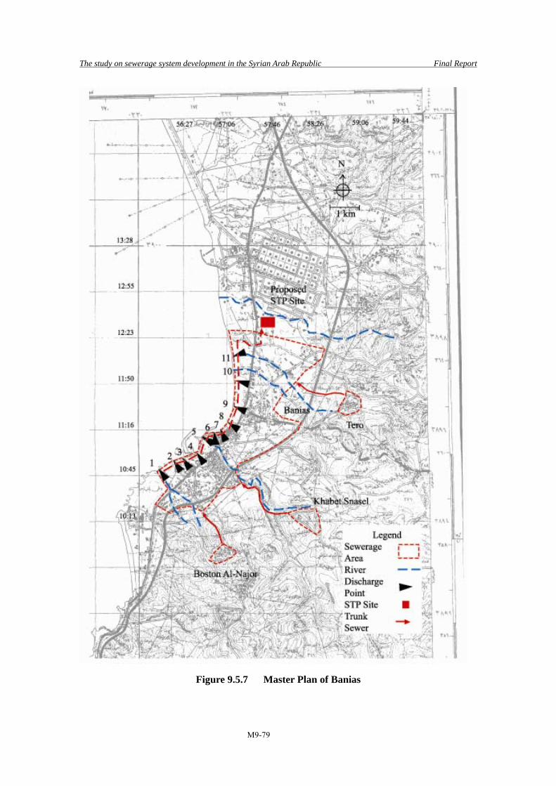
The study on sewerage system development in the Syrian Arab Republic Final Report
M9-79
Figure 9.5.7 Master Plan of Banias

The study on sewerage system development in the Syrian Arab Republic Final Report
M9-80
9.5.3 Mayadin, Deir-Ez-zor Governorate
(1) Study Area Deir-Ez-zor Governorate is located in downstream of the Euphraties River and its population is about one million. There are three districts, Deir-Ez-zor, Abu-Kamal, and Mayadin, in Deir-Ez-zor Governorate. Mayadin consists of three sub-districts, Mayadin, Zeban, and Asharah. Population of Mayadin Sub-Districts is about 86,000 and about half, 44,000, population live in Mayadin. Mayadin Sub-District has 8 communities such as Mayadin.
Although Taiba and Makhan were not included in the Macro Plan, these areas will be treated as part of the study area from the aspects listed below.
• Taiba is neighboring city with Mayadin in its downstream side. Since discharge point from Taiba is very near from Mayadin discharge point, these two areas should be treated as combined system.
• Discharge point from Makhan is located 3.5 km downstream of Taiba’s discharge point. However, difference of ground level of these two discharge points is very small. Wastewater from Makhan can be easily pumped up to Taiba.
• Engineers of Mayadin had already agreed to establish combined system among Taiba, Makhan, and Mayadin.
Master plan area in Mayadin district is shown in Figure 9.5.8: (2) Planned Population and Volume of Wastewater Population and volume of wastewater of Mayadin is as shown in Table 9.5.14. Wastewater volume in 2025 for Mayadin, Taiba, and Makhan will be 13,974, 1,323, 2,187 m3/day, respectively.
Table 9.5.14 Planning Parameters of Mayadin
Items Unit 2004 2010 2015 2020 2025 Mayadin Population per. 44,028 60,200 72,400 82,400 90,300 per capita Daily Average 129 135 142 148 155 Wastewater Daily max LCD 150 157 165 172 180 Peak Hourly 250 262 275 287 300 Tourist % 0 0 0 0 0 Generated Daily Average 5,678 8,152 10,270 12,220 13,974 Wastewater Daily max m3/day 6,594 9,466 11,927 14,191 16,228 Peak Hourly 10,989 15,777 19,878 23,652 27,047Taiba Population per. 6,061 7,600 8,700 9,500 10,100
Figure 9.5.8 Master Plan Area in Mayadin District

The study on sewerage system development in the Syrian Arab Republic Final Report
M9-81
Table 9.5.14 Planning Parameters of Mayadin
Items Unit 2004 2010 2015 2020 2025 per capita Daily Average 109 115 120 125 131 Wastewater Daily max LCD 127 133 139 146 152 Peak Hourly 211 222 232 243 253 Tourist % 0 0 0 0 0 Generated Daily Average 661 871 1,044 1,192 1,323 Wastewater Daily max m3/day 768 1,011 1,213 1,384 1,536 Peak Hourly 1,280 1,685 2,021 2,307 2,560Makhan Population per. 10,086 12,600 14,300 15,700 16,700 per capita Daily Average 109 115 120 125 131 Wastewater Daily max LCD 127 133 139 146 152 Peak Hourly 211 222 232 243 253 Tourist % 0 0 0 0 0 Generated Daily Average 1,101 1,444 1,716 1,970 2,187 Wastewater Daily max m3/day 1,278 1,677 1,993 2,288 2,539 Peak Hourly 2,130 2,794 3,322 3,813 4,232Total Population per. 60,175 80,400 95,400 107,600 117,100 Generated Daily Average 7,440 10,466 13,031 15,383 17,483 Wastewater Daily max m3/day 8,640 12,154 15,133 17,864 20,303 Peak Hourly 14,400 20,257 25,222 29,773 33,839
Note) LCD : liter/capita/day
(3) Investigation on Raw Sewage Discharging Points Physical features of the existing raw sewage discharging points are summarized in the Table 9.5.15. The discharging No.2 is planned to abandoned and shifted to the No.3. The necessary sewer between No.2 and No.3, having diameter of 1,500 mm, is now being installed. At No.4 the sewage collected from Taiba area will be discharged. Because the lateral sewer networks are still being under construction, the sewage has not been discharged yet when our survey was conducted. At No.5 the sewage collected from Makhan area is discharged, maybe including some irrigation water.
Table 9.5.15 Discharge Points in Mayadin
Location Latitude N Longitude E Level Remarks 1 35°01′37.3″ 40°27′01.8″ 188 Mayadin 2 35°01′30.5″ 40°27′47.1″ 191 Mayadin 3 35°01′15.4″ 40°28′40.1″ 189 Mayadin D 1.0m 4 35°00′21.8″ 40°29′10.3″ 186 Taiba D 1.0m 5 34°59′06.7″ 40°30′32.8″ 185 Makhan 0.15.1 ×
water depth=8cm
(4) Selection of STP Site The engineers of Mayadin recommended that the location near the discharge point No.4 is promising for the site of STP. The reasons are as follows: • Because the proposed site locates between the discharge points of Mayadin and Taiba, the
sewage generated in both area can be collected and conveyed efficiently. • The proposed site is public owned and would be easily acquired without any cost.

The study on sewerage system development in the Syrian Arab Republic Final Report
M9-82
• Because there are no houses around the proposed site, environmental measures would not be required.
The location of the proposed STP sites is shown in Table 9.5.16.
Table 9.5.16 Location of the Proposed STP Site (Mayadin)
Latitude N Longitude E Level Available Area Land Cost Land Owner
Distance from
residential area
35°00′22.1″ 40°29′09.1″ 186 More than 6ha - Public 100m
There would be an alternative site near Makhan for the STP, downstream of the discharge point No.4, enable to collect sewage generated from three cities of Mayadin, Taiba and Makhan. However, in practice, the site near the discharging point No.4 would have advantages for following reasons: • Sewage volume of Mayadin and Taiba is overwhelmingly greater than that of Makhan. It
would be advantagous to construct the STP near Mayadin and Taiba. Because of the trunk sewers generally would require smaller dimenstion (diameter and length) when a STP site were located at the area where sewage generation were higher. In other words, if the STP were constructed in the Makhan side, installation of trunk sewer having larger diameter and longer would be required.
• Sewer invert elevation at the discharge point No.4 is about same height with the river water level. If the sewer were extended to the downstream, the extended sewer would be installed at lower level compared to the river water level. This would bring a risk of inflow of river water into the sewer and require preventive measures during construction stage.
Relationship between extended trunk sewer and river water level is shown in Figure 9.5.9:
Figure 9.5.9 Relationship between Extended Trunk Sewer and River Water Level
(5) Sewage Collection Plan 1) Trunk Sewer Plan The design of conveyance sewers from the existing sewer outlet No.3 and No.5 to the STP is as
Ground Level
River water LevelTaiba Discharge point No.4
Trunk Sewer
(Makhan)
STP

The study on sewerage system development in the Syrian Arab Republic Final Report
M9-83
illustrated in Figure 9.5.10 and Table 9.5.17.
Figure 9.5.10 Schematic Drawing of Trunk Sewers
Table 9.5.17 Design of Trunk Sewer
Flow rate Capacity Dia. I v Q Items
m3/day m3/s m3/s mm ‰ m/s m3/s Mayadin (No.3 - STP)
27,047 0.313 0.626 800 1.4 1.28 0.643
Makhan (No.5 - STP)
4,232 0.049 0.098 400 1.5 0.83 0.105
The sewage collected at the discharge point No.3 is planned to convey by a gravity sewer to the proposed STP. The sewage collected at the discharge point No.5 is planned to lift up by a new pumps installed and conveyed by a gravity sewer to the STP. The reasons why the sewage would be not conveyed by pressured sewer are as follows: • The length of the pressured sewer will be long as about 3.5 km, a hydrogen sulfide would
be generated at the outlet and would damage the concrete structures. Some countermeasures to protect the damages would be required.
• There are no obstacles such as channels crossing over the conveyance sewer between the discharge point No. 4 and No.5. A gravity type conveyance sewer can be installed at shallower depth along the bank of the Euphraties.
2) Pumping Station Plan The planned sewage flow is 4,232 m3/day or 2.9 m3/min. The design capacity of pumping station is proposed at 3.0 m3/min. (6) Planning of STP 1) Influent quality and Effluent standard Treated sewage in this case is to be discharged to Euphraties river. Data on influent quality and effluent standard has been presented in Table 9.5.18
STP No.5 Makhan D 400
1.5‰ L=3.5km
P
No.3 Mayadin
STP D 8001.4‰ L=1km

The study on sewerage system development in the Syrian Arab Republic Final Report
M9-84
Table 9.5.18 Incoming Sewage Quality and Effluent Standard in Mayadin
Maximum Allowed Limited effluent standard from STP (mg/l) Items
Discharge mode to water-body
/ Condition of re-use BOD SS NH3-N NO3-N T-N T-P Influent 310 360 74 24 Effluent Standard
Proposed effluent standard (River) 40 30 5 50
2) Summary of conditions and proposed facilities The conditions considered for planning and specifications of proposed facilities are listed in Table 9.5.19. It shall be noted that Makhan was excluded from the scope of this M/P. Makhan will be integrated to the proposed STP in future and at that moment, STP shall be expanded.
Table 9.5.19 Summary of Conditions and Proposed Facilities
Items Contents Average wastewater (m3/d) 15,300 Hourly max wastwater (m3/d) 29,610 Sludge (kgDS/d) 3,787 Sludge (m3/d) 9.5 Moisture content (%) 60 Treatment method OD + Mechanical Thickening + Drying Bed Grit chamber (No.-w×L) 2-1.4m×6m Main P (No.-D×power) 5-φ200mm×11kw Reactor (No.-W×L×H) 8-4.5m×140m×3.0m(high rate) Final sedimentation tank 8-φ15m Disinfection channel 2-2m×21×1.9m Mechanical Sludge Thickener 2-1,893kg/d Drying Bed 24-15m×43m Required land area (ha) 5.9
3) Sewage treatment method The agricultural land along the river bank is available for STP establishment. It is vast public land and good farm, so consideration should be given to acquire the minimum land for STP construction. For selection of treatment method it is important to consider that water for irrigation is abundant, and environmental capacity of Euphraties is large., Therefore, it is possible to select a primary treatment method if not counting on effluent standard, like only primary sedimentation. However, the water from the river provides for the water supply in many cases downstream. Therefore, primary treatment would not be sufficient, and secondary treatment has been proposed. Conventional Extended Aeration, OD, or Wet-land is applicable as the treatment method for this scale of wastewater flow. As the economic value of land is high, wet-land which demand larger land, would be excluded, and Conventional Activated Sludge for comparison with

The study on sewerage system development in the Syrian Arab Republic Final Report
M9-85
Conventional Extended Aeration and OD is added. Since de-nitrification is not included as treatment target, BOD-SS loading of OD is set as the same rate as of Conventional Extended Aeration. Preservation of agricultural land has been considered important while comparison and evaluation of methods is carried out. As a result, OD is proposed in terms of easiness of O&M and structural reason considering that the load of OD is relatively small and it is better to construct OD on such land near river for which bearing capacity of foundation must be small. Comparison of treatment process in Mayadin is shown in Table 9.5.20.
Table 9.5.20 Comparison of Treatment Process in Mayadin
Items OD Conventional
extended aeration Conventional
Activated Sludge Possibility of layout + + + Preservation of farm land + + ++ Correspondence to load fluctuation
+ +
Sludge Reduction + + Offensive odor Problem + + Simple equipment ++ + Easiness of operation ++ + Construction cost + Maintenance cost ++ + Evaluation 11 points 9 points 3 points
4)Sludge treatment method Sufficient land is available for any method. However, generated sludge cannot be thickened by gravity, and therefore Mechanical Thickening and Drying Bed are proposed. 5) Special Consideration on facility Planning
• STP site is located within flood plain, so embankment and bank protection must be constructed.
• The foundation must be soft ground because it is located in flood plain, so light weight structure like the digging ditch covered by rubber sheet would be preferred. Foundations for the aerators would be required though.
• Proposed area of Mayadin may be coupled with neighboring cities along the river, and STP would possibly require extension, because centralization of management of sewage facilities would have economical advantages in this region. However, at this moment it is uncertain, so land requirement for STP for future population of Mayadin and Taiba should be estimated and land acquisition should be carried out as enough land is available near STP for the future plan.

The study on sewerage system development in the Syrian Arab Republic Final Report
M9-86
Maser plan of Mayadin is shown in Figure 9.5.11:
Figure 9.5.11 Master Plan of Mayadin
Future Plan

The study on sewerage system development in the Syrian Arab Republic Final Report
M9-87
9.5.4 Malkieh, Hassakeh Governorate
(1) Study Area Hassakeh Governorate is located in northern area of the Euphraties River. A major part of the governorate is located in the Al-Khabour River basin and eastern part of the governorate including Malkieh exists in the Tigris River basin. There are four districts, Hassakeh, Al-Qamishli, Malkieh, and Ras Arain in the governorate. Malkieh District consists of three sub-districts namely, Malkieh, Al-Jawadieh, and Al-Yarobieh. There are 108 communities in Malkieh Sub-district. Population in Malkieh is about 26,000 and about 16,000 for Al-Mabadeh. Other communities are rather small and their populations are less than 3,000. Development in Malkieh will occupy a hilly area with a good run-off for water since the river crosses the middle of the city. The river flows into a dam that was constructed for irrigation. The sewer pipeline system in the city is already almost developed. To avoid the discharge of raw wastewater into the dam lake, the raw wastewater transmission pipeline should reach the downstream of the dam. The wastewater that is discharged flows into the Tigris River. On the way to the Tigris River, there are many small scale communities, along the riverbanks that depend on wells as their water source. To reduce the risk of groundwater contamination, the development of a sewage system in Malkieh is urgently required. The Master Plan area in Maikieh district is shown in Figure 9.5.12: (2) Planned Population and Volume of Wastewater The population and volume of wastewater in Malkieh is as shown in Table 9.5.21.
Figure 9.5.12 Master Plan Area in Malkieh District
Malkieh

The study on sewerage system development in the Syrian Arab Republic Final Report
M9-88
Table 9.5.21 Planning Parameters of Malkieh
Items Unit 2004 2010 2015 2020 2025 Population per. 26,311 29,100 31,200 33,000 34,500per capita Daily Average 109 115 120 125 131Wastewater Daily max LCD 127 133 139 146 152 Peak Hourly 211 222 232 243 253Tourist % 0 0 0 0 0Generated Daily Average 2,871 3,334 3,745 4,141 4,518Wastewater Daily max m3/day 3,334 3,872 4,349 4,809 5,246 Peak Hourly 5,557 6,453 7,248 8,015 8,744
Note) LCD : liter/capita/day
(3) Investigation on Raw Sewage Discharge Points The sewage collected from the urban area is discharged at a point located downstream of the dam within the vicinity of the proposed STP. The outlet is about 40 m below the level of the urban area. The diameter of the sewer is 800 mm. (4) Selection of STP Site All sewage generated from the city is being diverted around the dam and discharged downstream of the dam. City officials plan to construct the STP near the discharge point. This location would be appropriate for the following reasons: • No houses exist in the STP site and therefore, no resettlement will be required. • Becasuse the site is remote from residential areas, environmental measures would not be
required. • Since the site is located lower than the residential area, it could efficiently collect the
sewage generated. • The proposed site is not flat but can be developed by filling and cutting work. • An appropriate discharge channel is available near the proposed site. Diagrammatic sketch of discharge point is shown in Figure 9.5.13. Location of proposed STP site in Malkieh is shown in Table 9.5.22.
Figure 9.5.13 Diagrammatic Sketch of Discharge Point
Dam
Abandoned
Discharge Point STP
River
Malkieh
Discharge Point

The study on sewerage system development in the Syrian Arab Republic Final Report
M9-89
Table 9.5.22 Location of Proposed STP Site (Malkieh)
No Latitude N Longitude E Level Available Area Land Cost
Land Owner
Distance from residential area
1 37°11′02.0″ 42°09′56.5″ 444 m More than 2ha - Public 1,500m (5) Sewage Collection System It is proposed that a structure be installed to divert the sewage from the existing trunk sewer and convey to the proposed STP. Table 9.5.23 summarizes the design of the conveyance sewer.
Table 9.5.23 Design of Trunk Sewer
Flow rate Capacity Diameter Inclination v Q m3/day m3/s m3/s mm ‰ m/s m3/s 8,744 0.101 0.202 500 1.7 1.03 0.202
(6) Planning of STP 1)Influent quality and Effluent standard Treated sewage will be discharged to river. Incoming sewage quality and effluent standard in Markieh are shown in Table 9.5.24.
Table 9.5.24 Incoming Sewage Quality and Effluent Standard in Markieh
Maximum Allowed Limited effluent standard from STP (mg/l) Items
Discharge mode to water-body
/ Condition of re-use BOD SS NH3-N NO3-N T-N T-P
Influent 310 360 74 24Effluent Standard
Proposed effluent standard (River)
40 30 5 50
The treated sewage is expected to be used for the irrigation of cotton, where cotton is assumed to be an industrial crop. The effluent standard for the irrigation of industrial crops is BOD 150 mg/l, which is more lenient than 30mg/l for discharge into the river. Therefore, the effluent standard for discharge into the river shall be applied. 2)Summary of conditions and proposed facilities Planning conditions and results are listed in Table 9.5.25.
Table 9.5.25 Summary of Conditions and Proposed Facilities
Items Contents Average wastewater (m3/d) 4,518 Hourly max wastwater (m3/d) 8,744 Sludge (kgDS/d) 1,119 Sludge (m3/d) 2.8 Moisture content (%) 60
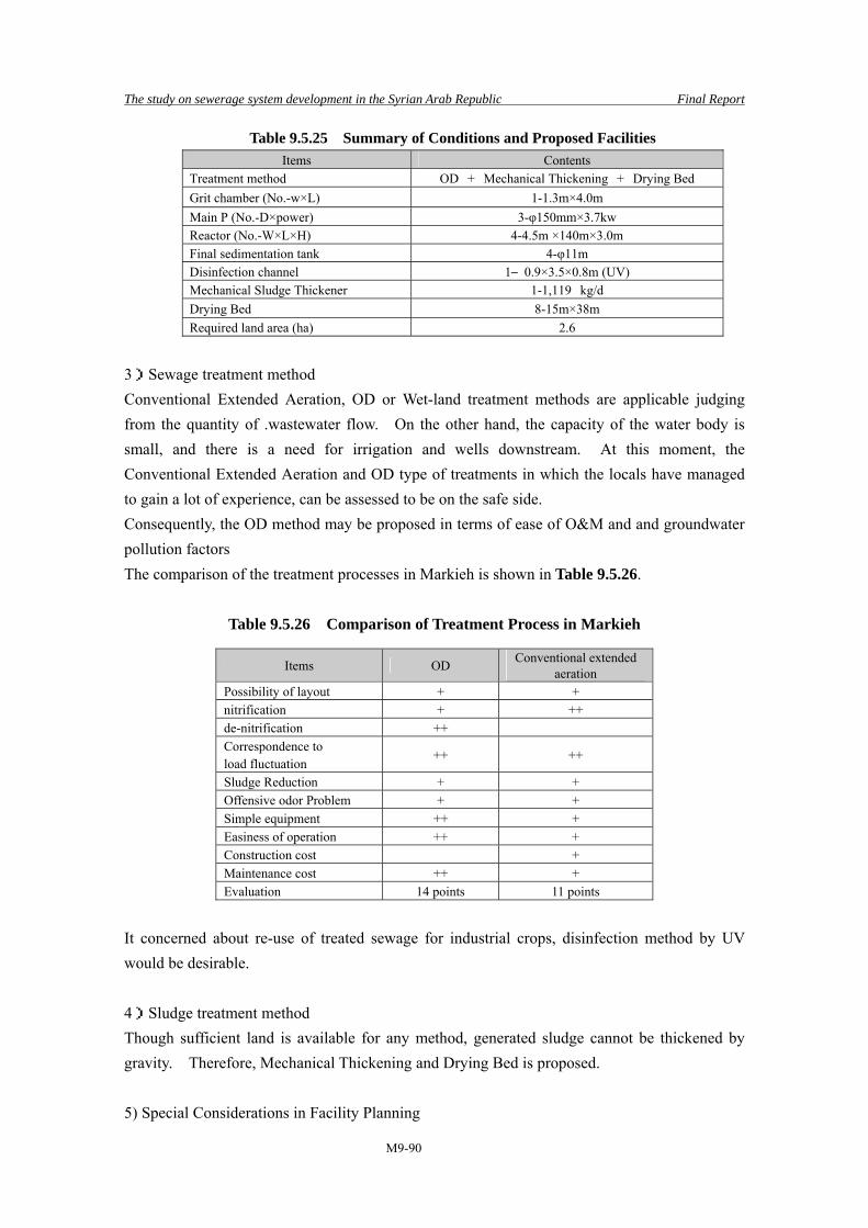
The study on sewerage system development in the Syrian Arab Republic Final Report
M9-90
Table 9.5.25 Summary of Conditions and Proposed Facilities Items Contents
Treatment method OD + Mechanical Thickening + Drying Bed Grit chamber (No.-w×L) 1-1.3m×4.0m Main P (No.-D×power) 3-φ150mm×3.7kw Reactor (No.-W×L×H) 4-4.5m ×140m×3.0m Final sedimentation tank 4-φ11m Disinfection channel 1―0.9×3.5×0.8m (UV) Mechanical Sludge Thickener 1-1,119 kg/d Drying Bed 8-15m×38m Required land area (ha) 2.6
3)Sewage treatment method Conventional Extended Aeration, OD or Wet-land treatment methods are applicable judging from the quantity of .wastewater flow. On the other hand, the capacity of the water body is small, and there is a need for irrigation and wells downstream. At this moment, the Conventional Extended Aeration and OD type of treatments in which the locals have managed to gain a lot of experience, can be assessed to be on the safe side. Consequently, the OD method may be proposed in terms of ease of O&M and and groundwater pollution factors The comparison of the treatment processes in Markieh is shown in Table 9.5.26.
Table 9.5.26 Comparison of Treatment Process in Markieh
Items OD Conventional extended aeration
Possibility of layout + + nitrification + ++ de-nitrification ++ Correspondence to load fluctuation
++ ++
Sludge Reduction + + Offensive odor Problem + + Simple equipment ++ + Easiness of operation ++ + Construction cost + Maintenance cost ++ + Evaluation 14 points 11 points
It concerned about re-use of treated sewage for industrial crops, disinfection method by UV would be desirable. 4)Sludge treatment method Though sufficient land is available for any method, generated sludge cannot be thickened by gravity. Therefore, Mechanical Thickening and Drying Bed is proposed. 5) Special Considerations in Facility Planning

The study on sewerage system development in the Syrian Arab Republic Final Report
M9-91
As the STP site is located on a relatively low ground, an extended embankment will be constructed to avoid submergence. The foundation will be set on the embankment, so that a light structure like a digging ditch covered with a rubber sheet would be preferred. Foundations at the aerators are required though. Master plan of Malkieh is shown in Figure 9.5.14:

The study on sewerage system development in the Syrian Arab Republic Final Report
M9-92
Figure 9.5.14 Master Plan of Malkieh
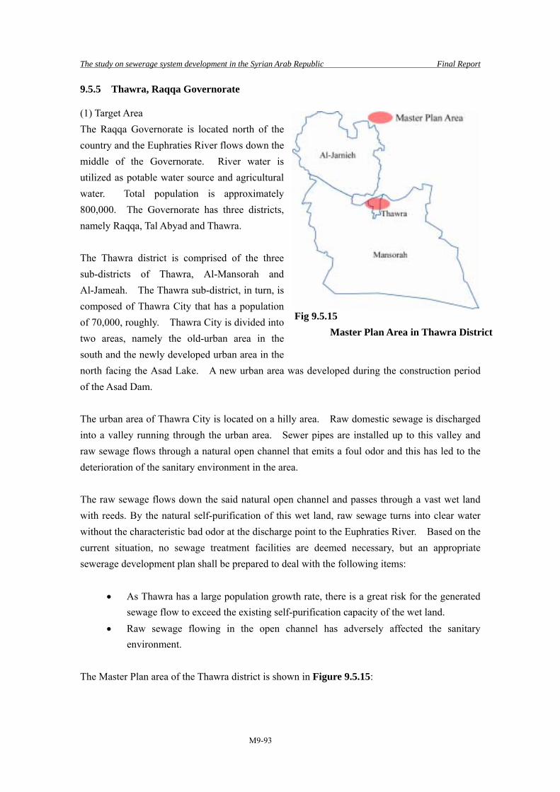
The study on sewerage system development in the Syrian Arab Republic Final Report
M9-93
9.5.5 Thawra, Raqqa Governorate
(1) Target Area The Raqqa Governorate is located north of the country and the Euphraties River flows down the middle of the Governorate. River water is utilized as potable water source and agricultural water. Total population is approximately 800,000. The Governorate has three districts, namely Raqqa, Tal Abyad and Thawra. The Thawra district is comprised of the three sub-districts of Thawra, Al-Mansorah and Al-Jameah. The Thawra sub-district, in turn, is composed of Thawra City that has a population of 70,000, roughly. Thawra City is divided into two areas, namely the old-urban area in the south and the newly developed urban area in the north facing the Asad Lake. A new urban area was developed during the construction period of the Asad Dam.
The urban area of Thawra City is located on a hilly area. Raw domestic sewage is discharged into a valley running through the urban area. Sewer pipes are installed up to this valley and raw sewage flows through a natural open channel that emits a foul odor and this has led to the deterioration of the sanitary environment in the area.
The raw sewage flows down the said natural open channel and passes through a vast wet land with reeds. By the natural self-purification of this wet land, raw sewage turns into clear water without the characteristic bad odor at the discharge point to the Euphraties River. Based on the current situation, no sewage treatment facilities are deemed necessary, but an appropriate sewerage development plan shall be prepared to deal with the following items:
• As Thawra has a large population growth rate, there is a great risk for the generated sewage flow to exceed the existing self-purification capacity of the wet land.
• Raw sewage flowing in the open channel has adversely affected the sanitary environment.
The Master Plan area of the Thawra district is shown in Figure 9.5.15:
Fig 9.5.15 Master Plan Area in Thawra District

The study on sewerage system development in the Syrian Arab Republic Final Report
M9-94
(2) Design Population and Sewage Flow Design population and relevant data on sewage flow calculation are shown in Table 9.5.27:
Table 9.5.27 Planning Parameters of Thawra
Items Unit 2004 2010 2015 2020 2025 Population per. 69,425 80,300 90,700 102,400 115,600per capita Daily Average 129 135 142 148 155Wastewater Daily max LCD 150 157 165 172 180 Peak Hourly 250 262 275 287 300Tourists % 0 0 0 0 0Generated Daily Average 8,953 10,873 12,866 15,186 17,889Wastewater Daily max m3/day 10,397 12,627 14,942 17,636 20,775 Peak Hourly 17,328 21,045 24,903 29,393 34,625
Note) LCD : liter/capita/day
(3) Investigation on Raw Sewage Discharging Points According to the results of field survey, there are three raw sewage discharging points. Table 9.5.28 shows the coordinates and pipe sizes. However, discharge point No.3was unidentified. Discharge point No.1 was constructed recently and no sewage was discharged as sewer pipe was not connected yet. Since discharge point No.2 was submerged, sewage flow could not be confirmed but it was assumed that considerable sewage volume runs.
Table 9.5.28 Discharge Points of Thawra
Location Latitude Longitude Level Remarks 1 35°50′34.2″ 38°34′13.3″ 275 Dia. 1,000mm 2 35°50′28.5″ 38°33′37.1″ 292 Dia. 700mm 3 - - - Unidentified
(4) Selection of STP Site According to the Governorate engineer, the land near discharge point No.1 was proposed as the STP construction site. As this land has a lower ground elevation, it has not been utilized as agricultural land and thus land acquisition will be easy. Further, since there are no housing units in the surrounding areas, no strict environmental countermeasure will be needed. Therefore, the said land is appropriate for the STP construction site. Table 9..5.29 indicates the relevant data on the site.
Table 9.5.29 Location of Proposed STP Site (Thawra)
Location Latitude Longitude Level Available Area Land Cost
Land Owner
Distance fromresidential area
1 35°50′38.7″ 38°34′19.8″ 278 More than 1 ha - Public 1,300m
(5) Sewage Collection Plan 1) Trunk Sewer Plan A trunk sewer shall be installed to send discharged sewage to the STP, provided that the

The study on sewerage system development in the Syrian Arab Republic Final Report
M9-95
sewage flow of discharge point No.1 and 2 is 40% of the total flow, while that of discharge point No.3 is 20%. Refer to Figure 9.5.16 and Table 9.5.30.
Figure 9.5.16 Schematic Drawing of Trunk Sewer
Table 9.5.30 Design of Trunk Sewer
Flow Capacity Diameter I v Q Items
m3/day m3/s m3/s mm ‰ m/s m3/s No.1, 2 13,850 0.160 0.320 600 1.7 1.13 0.329 No.3 6,925 0.080 0.160 500 1.5 0.97 0.190
(6) Sewage Treatment Plant Plan 1) Incoming Sewage Quality and Effluent Standard Treated sewage will be discharged into river. Refer to Table 9.5.31 for the proposed effluent
standard:
Table 9.5.31 Incoming Sewage Quality and Effluent Standard
Discharge mode to water-body
/ Condition of re-use Maximum allowed effluent standard from STP (mg/l)
Items
Indices BOD SS NH3-N NO3-N T-N T-P Incoming Sewage
310 360 74 24
Effluent Standard
Proposed Effluent Standard (to River)
40 30 5 50
2) Summary of Conditions and proposed Facilities The summary of design conditions and data on proposed facilities are shown in Table 9.5.31:
No.2 Discharge
STP D 600mm 1.7‰ L=1,100m
No.1 Discharge
D 600mm 1.5‰ L=200 m
No.3 Discharge
D 500mm 1.7‰ L=100 m

The study on sewerage system development in the Syrian Arab Republic Final Report
M9-96
Table 9.5.32 Summary of Conditions and Proposed Facilities
Items Contents Population 115,600 Daily Average Sewage Flow (m3/d) 17,889 Hourly Maximum Sewage Flow (m3/d) 34,625 Sludge (kgDS/d) 2,361 Sludge (m3/d) 5.9 Moisture content (%) 60 Treatment processes Existing Wet-land + Primary Settling Tank +Drying Bed
Grit chamber (No.-w×L) 2-1.3m×7.5m Main P (No.-D×power) 5-φ250mm×11kw Primary Settling Tank 4-φ10 Drying Bed 20-15m×32m Required land area (ha) 2.4
3) Sewage Treatment Method Considering that the Euphraties River (the receiving water body of treated sewage) has a large environmental capacity and that Reed Bed, the existing natural system has been functioning well, the existing Reed Bed will be utilized as a Wet Land and a Primary Settling Tank shall be constructed to cope with future population growth. A possible alternative is the construction of an STP with 120,000 PE in the land located between Safsafe and Thawra but as this land has a higher elevation, a pumping station would be required. From the viewpoint of the optimization of existing facilities and power saving, this alternative lacks rationality.
4) Sludge Treatment Method If a Primary Settling Tank will be constructed, raw sludge will be generated. As there is vast land available south of Thawra City that could be used as sludge reclamation land, sludge can be transferred to this location for treatment. Sludge treatment by Gravel Thickening and Drying Bed will be economical. However, considering the environmental aspect, the establishment of a regional compost factory has been planned for future construction to gather sludge from several STPs.
5) Special Consideration on Facility Planning The Study Team has proposed the establishment of Primary Settling Tanks and Sludge Drying Beds as supplemental facilities for the existing Reed Bed. However, there are several issues to be addressed towards project implementation as follows: The establishment of the sewerage system in Thawra was intended basically to maintain the natural self-purification of existing reed beds for sewage treatment, and to effect budget savings simultaneously. The self-purification capacity is expected to be sufficient for
The study on sewerage system development in the Syrian Arab Republic Final Report
M9-97
purposes of the present service area in 2007, thus, the prompt construction of the STP would be not required. But in the future, when the capacity of the reed bed is expected to be exhausted due to the increase in population, several options should be considered. For example, the expansion of the reed bed or the construction of new supplemental facilities such as a primary sedimentation tank and sludge treatment facility shall be carried out. Therefore, the M/P shall be prepared considering these long-term factors. On the other hand, in formulating the future option, the Raqqa Governorate should monitor the sewage quality (at inlet and outlet) in order to recognize the relationship between the growth of the population and self-purification capacity of reed beds. In this way, the Governorate would be able to determine the exact year when the reed beds would need expansion or when supplemental facilities would be introduced. The collection of following fundamental information shall be carried out and compiled by the Governorate from hereon for subsequent use in future design:
a) Location of the Main Trunks b) Area of reed beds and flood plains c) Pollution loading on the reed beds d) Monitoring of treated sewage quality discharged to the river
6) Proposal on Fundamental Data Collection by Governorate Survey a) Location of Main Trunks
Location and elevation of the main trunks that reach the reed bed are not available. It is impossible to design the supplemental facilities without considering data on existing facilities. For this purpose, a topographic survey of main trunks located outside the city shall be conducted and the location of these main trunks shall be confirmed by the topographic map. A ;ongitudinal section shall also be prepared.
Survey b) Area of reed beds and flood plain
The area of the existing reed beds and its drawing is not defined on the map. So a topographic survey of the reed bed site shall also be carried out. At the same time, the areas of the reed beds and flood plain shall be defined on the map. Equally, a specific area within the reed bed that wll be identified for the location of the sewage treatment should be identified.
Survey c) Pollution Loading to the reed bed
Though the existing reed bed seems to have a sufficient treatment capacity to contain the present loading, the actual load is not well defined. To accomplish this, the population growth rate, flow and fundamental sewage indices of BOD, SS, COD, NH3, NO3, DO, Coliform, etc. should be periodically monitored for each

The study on sewerage system development in the Syrian Arab Republic Final Report
M9-98
main trunk.
Survey d) Monitoring of treated sewage quality discharged to the river Treated effluent from the reed bed looks very clear at the discharge point near the river but the actual treated sewage quality is still unknown. Along with the population growth, the pollution load will simultaneously increase and this will apparently affect the capacity of the reed bed. Therefore, through the successive monitoring of the incoming pollution load on the reed bed and the treated sewage quality, the Government would be able to decide appropriately when the supplemental facilities shall be constructed.
Refer to Figure 9.5.17: :
Figure 9.5.17 Schematic Drawing of Existing Reed Bed and Future Plan Master plan of Thawra is shown in Figure 9.5.18:

The study on sewerage system development in the Syrian Arab Republic Final Report
M9-99
Figure 9.5.18 Master Plan of Thawra

The study on sewerage system development in the Syrian Arab Republic Final Report
M9-100
9.5.6 Muzerib, Dar’aa Governorate
(1) Target Area The GCEC has already prepared the study on the sewerage system development for this area. According to this study, the proposed centralized sewerage system will collect sewage generated in the three cities of Muzerib, Yaduda and Atman for treatment in one STP. Comparison was done on five alternatives for the proposed STP site and the optimum site was chosen. The proposed site is an agricultural land located between Muzerib and Yaduda. These three cities are medium-scale cities populated by more than 8,000 persons and geographically adjoin each other. Their order of location from upstream to downstream is Atman, Yaduda and Muzerib. The largest city is Muzerib. The distance between Atman and Yaduda is about 6 km and that between Yaduda and Muzerib is 5 km, approximately. As a result of the examination indicated in the Macro Plan, Atman will be served by a decentralized system, while Yaduda and Muzerib will be served by a centralized system. The major issue to be addressed by the Master Plan is the selection of the proposed STP construction sites. The Master Plan area in Muzerib district is shown in Figure 9.5.19: (2) Design Population and Sewage Flow
Design population and sewage flow in study area is shown in Table 9.5.33:
Table 9.5.33 Planning Parameters of Muzerib Items Unit 2004 2010 2015 2020 2025 Muzelib Population per. 12,640 14,200 15,500 16,700 17,900 per capita Daily Average 109 115 120 125 131 Wastewater Daily max LCD 127 133 139 146 152 Peak Hourly 211 222 232 243 253 Tourists % 0 0 0 0 0 Generated Daily Average 1,379 1,627 1,860 2,096 2,344 Wastewater Daily max m3/day 1,602 1,889 2,161 2,434 2,722 Peak Hourly 2,670 3,149 3,601 4,056 4,537Yaduda Population per. 8,967 10,000 10,900 11,800 12,600 per capita Daily Average 109 115 120 125 131 Wastewater Daily max LCD 127 133 139 146 152 Peak Hourly 211 222 232 243 253 Tourists % 0 0 0 0 0
Figure 9.5.19 Master Plan Area in Muzerib District

The study on sewerage system development in the Syrian Arab Republic Final Report
M9-101
Table 9.5.33 Planning Parameters of Muzerib Items Unit 2004 2010 2015 2020 2025 Generated Daily Average 978 1,146 1,308 1,481 1,650 Wastewater Daily max m3/day 1,136 1,331 1,519 1,720 1,916 Peak Hourly 1,894 2,218 2,532 2,866 3,193Atman Population per. 8,929 11,400 13,200 14,600 15,700 per capita Daily Average 109 115 120 125 131 Wastewater Daily max LCD 127 133 139 146 152 Peak Hourly 211 222 232 243 253 Tourists % 0 0 0 0 0 Generated Daily Average 974 1,306 1,584 1,832 2,56 Wastewater Daily max m3/day 1,131 1,517 1,840 2,128 2,387 Peak Hourly 1,886 2,528 3,067 3,546 3,979Total Population per. 30,536 35,600 39,600 43,100 46,200 Generated Daily Average 3,332 4,079 4,753 5,409 6,050 Wastewater Daily max m3/day 3,870 4,737 5,520 6,281 7,025 Peak Hourly 6,449 7,895 9,200 10,468 11,709Total Population per. 21,607 24,200 26,400 28,500 30,500Muzelib Generated Daily Average 2,357 2,773 3,168 3,577 3,994Yaduda Wastewater Daily max m3/day 2,738 3,220 3,680 4,154 4,638 Peak Hourly 4,564 5,367 6,133 6,922 7,730
Note) LCD : liter/capita/day
(3) Investigation of Raw Sewage Discharging Points Coordinates of discharge points located by GPS survey were shown in Table 9.5.34:
Table 9.5.34 Discharge Points of Muzerib
Name of Discharge Points N E Diameter Yaduda Discharge Point 32°40′38.1″ 36°02′59.6″ Muzerib Discharge Point 32°42′22.5″ 36°00′34.1″ Dia.= 1,000 mm
(4) Selection of STP Site a) STP Site Two STP construction sites were identified for further examination. From the viewpoint of economy, the site near the existing Muzerib discharge point is preferable but as both of the proposed sites are 4 km away from Muzerib, the discharge point, they are not suitable as STP construction sites. Hereinafter, a comparative analysis was conducted on these two alternatives. Refer to Table 9.5.35 to Table 9.5.39:
In both site, there are no housing units and therefore, no resettlement will be required. Table 9.5.35 Characteristics of Proposed STP Site
Case Characteristic of the Sites Case 1 Site proposed by engineer of Dara’a Governorate. 4 km away from
Muzerib discharge point in downstream. Case 2 The optimum site extracted comparison study executed on five alternatives by
GCEC. 4 km away from Muzerib discharge point in upstream.
Explanation drawing of case 1 and case 2 are shown in Figure 9.5.20 and 9.5.21:

The study on sewerage system development in the Syrian Arab Republic Final Report
M9-102
Table 9.5.36 Location of the Proposed STP Site (Muzerib)
Site N E Level Land-use Land Cost(SP/m2)
Land Owner
Distance fromresidential area
No.1 STP Site 32°42′03.3″ 35°58′42.1″ 420 Farm land 500 Private 150m No.2 STP Site 32°41′00.0″ 36°02′02.6″ 461 Farm land 1,000 Private 300m
Figure 9.5.20 Explanation Drawing of Case 1
Table 9.5.37 Construction Cost of Case 1
Facility Number Unit cost Cost Dia. 500 4,000 m 6,000SP/m 24.0 Mil.SP Dia. 400 5,800 m 4,500SP/m 26.1 Mil.SP Total 50.1 Mil.SP
Figure 9.5.21 Explanation Drawing of Case 2
Table 9.5.38 Construction Cost of Case 2
Facility Number Unit cost Cost D 400 1,800 m 4,500 SP/m 8.1 Mil SP D 250 4,000 m 3,000 SP/m 12.0 Mil SP PS 3.0 m3/min 15 Mil.SP 15.0 Mil SP Maintenance 30 Years 0.5 Mil.SP 15.0 Mil SP Total 50.1 Mil SP
b) Head of Pump Actual Head=461 - 441 = 20 m Pipe Friction Loss=0.006×4,000 = 24 m Total Head=20 + 24 = 44 m Daily Average Sewage Flow in 2004 = 1,112 m3/day Power Consumption=1,112×44×0.0045×365= 80,000 kWh/Year Electricity=80,000 kWh×2.5 SP/kWh=200,000 SP/Year
STP Muzerib Yaduda Dia.= 400mm I= 1.5‰ L=1.8 km
Pumping Station Q=3.0 m3/min
Dia.= 250mm L= 4km
STP Muzerib Yaduda D 400mm 1.5‰ L=5.8 km
D 500mm 1.4‰ L=4km

The study on sewerage system development in the Syrian Arab Republic Final Report
M9-103
As planned, a pumping station for transporting the whole sewage generated is indicated in Muzerib. However, it cannot be designed as a simplified facility such as the manhole-type pumping station. A general pumping station shall be planned. The necessary equipment for the pumping station are the following:
• Generator as an emergency facility in case of power failure • Air injector to restrain the generation of Hydrogen Sulfide that is likely to build up in
longer forced sewage transmission • Serge tank to prevent water hammer • Pump with higher head • Sedimentation tank and screening removal equipment • Anti-odor measures shall be taken as housing units are located nearby
Electricity was calculated based on the computed result, wherein the electricity needed to pump sewage was estimated to be 1 m3 to 1 m higher is 0.0045 kwh/m3/m; the annual electricity was calculated as 200,000 SP. The O&M cost of the pumping station was estimated to be 500,000 SP/Year including labor cost. Electricity needed to pump sewage equivalent to 1m3/min to 1 m higher was computed using the following formula:
kwh.).(.
.)(HQr.P 270150170
111163011630=+×
×××=α+×
η×××
=
If the pump is operated for 1 hour, the pumped sewage volume will be 60 m3. Thus, the needed electricity per 1 m3 was computed by dividing the figure by 60. (0.27/60=0.0045)
Table 9.5.39 Comparison of Proposed STP Sites
Items Case1 Case 2 Remarks 1. Construction Cost
△ ○ Case 1 was calculated as 50.1 Mil.SP, while that of Case 2 was 35.1 Mil.SP.
2. O&M Cost ○ △ Case 2 requires annual O&M cost of 0.5Mil.SP 3. Length of Trunk
Sewer △ ○
Case 1 has larger trunk sewer length. 4 km longer than Case 2. Further pipe diameter is larger.
4. Pumping Station ○ △
Case 2 needs pumping station. Pump shall have higher head.
5. Effect on Groundwater
○ △ As STP proposed in Case 2 located near to production wells in Muzerib, adverse effect is anticipated.
6. Re-use as Irrigation Water △ ○
Since Case 2 can discharge treated sewage into channel located upstream, it can be utilized as irrigation water efficiently.
7. Surrounding Conditions △ ○
There is no residential area near STP site of Case 2, while there are residential area 500 m away from STP site of Case 1.
8. Sewage generated in neighboring villages
○ △ Case 1 can collect and treat sewage generated in three communities located downstream of Muzerib.
9. Land Acquisition Cost
○ △ Land acquisition cost of Case 1 was 500 SP/m2, while that of Case 2 was 1,000 SP/m2.

The study on sewerage system development in the Syrian Arab Republic Final Report
M9-104
According to the comparison shown in Table 9.5.39, number of ○ is 5 in Case 1 and that of Case 2 is 4. They are almost equivalent. However, the JICA Study Team selected Case 1 as the optimum plan owing to the following reasons:
• Total project cost inclusive of construction and O&M cost is almost equivalent. • As this area has an abundant agricultural water source, there is no need for the re-use of
treated sewage. • Though there are some communities 500 m away from the proposed STP construction
site in Case 1, the environmental impact caused by the STP can be minimized through the adoption of proper countermeasures.
• Long pressured sewage transmission tends to generate Hydrogen Sulfide that might cause corrosion of sewer pipe and treatment facilities.
• Pumping station needs equipment such as air injector, surge tank and anti-odor facility.
(5) Sewage Collection Plan 1) Trunk Sewer Plan Table 9.5.40 shows the design criteria and relevant data on the trunk sewer. In-pipe velocity of the force main was set at 1.0 m/s.
Table 9.5.40 Design of Trunk Sewer
Flow Capacity Diameter I v Q Items
m3/day m3/s m3/s mm ‰ m/s m3/s Yaduda-Muzerib 3,193 0.037 0.074 400 1.5 0.83 0.105Muzerib-STP 7,730 0.089 0.178 500 1.4 0.94 0.184Muzerib-STP(Case2) 4,537 0.053 0.053 250 6.0 1.03 0.050
(6) Sewage Treatment Plant Plan 1) Incoming Sewage Quality and Effluent Standard Treated sewage is discharged to Waji (river). As the ground water is abundant, there is no need to re-use treated sewage for irrigation. If the quality of the treated sewage is well within effluent standard for discharging into the river, this effluent could be used for the irrigation of fruit trees or grain. Refer to Table 9.5.41.

The study on sewerage system development in the Syrian Arab Republic Final Report
M9-105
Table 9.5.41 Incoming Sewage Quality and Effluent Standard
Items Discharge mode to
water-body / Condition of re-use
Maximum allowed effluent standard from STP (mg/l)
Indices BOD SS NH3-N NO3-N T-N T-P Incoming Sewage
310 360 74 24
Effluent Standard
Proposed Effluent Standard (to River) 40 30 5 50
Reference:Irrigation (Grain) 100 150 5 25
2) Summary of Conditions and Facilities Planning condition and summarized data on proposed facilities are shown in Table 9.5.42:
Table 9.5.42 Summary of Conditions and Proposed Facilities
Items Contents Population 30,500 Daily Average Sewage Flow (m3/d) 3,994 Hourly Maximum Sewage Flow (m3/d) 7,730 Sludge (kgDS/d) 527 Sludge (m3/d) 1.3 Moisture content (%) 60
Treatment processes Wet-land + Drying Bad
Grit chamber (No.-w×L) 1-0.9m×5m Main P (No.-D×power) 3-φ150mm×5.5kw Primary settling tank 2-φ6.5m Reed Bed 24-21m×37m Drying Bed 8-12m×22m
Required land area (ha) 4.9
3) Sewage Treatment Method As no groundwater contamination was observed, the environmental capacity has been sufficient to cope with the needs of the present population. However, since the residents depend on wells as potable water sources, the advanced sewage treatment method shall be employed to avoid groundwater contamination that might be caused by increased pollution load. The existing water quality of Waji will also be improved. OD, Conventional Extended Aeration and Constructed Wet Land treatment processes have been chosen for comparison based on the design sewage flow. Comparison of treatment processes is shown in Table 9.5.43:

The study on sewerage system development in the Syrian Arab Republic Final Report
M9-106
Table 9.5.43 Comparison of Treatment Processes
Items OD Conventional
extended aeration Constructed Wet Land
Land Availability + + + Nitrification + ++ + Denitrification ++ Re-use for Irrigation ++ + + Correspondence to load fluctuation
+ + +
Sludge Reduction + + Odour Problem + + Simple equipment ++ + +++ Easiness of operation ++ + +++ Construction cost + +++ Maintenance cost ++ + +++ Evaluation 15 points 11 points 16 points
If land is readily available, then a Constructed Wet Land with the cheapest construction cost and ease in O&M is the most suitable method. Moreover, as the STP site is located near communities and is visible to them, the reeds could serve as a good landscape. However, available data on nitrogen removal through the use of this method is not sufficient and careful examination is needed prior to adoption. However, treated sewage looks clean in both existing facilities in Thawra and Harran Al Awameed and currently there is no need to re-use treated sewage for irrigation. Therefore, the Constructed Wet Land method is applicable in cases where the treated sewage is discharged into the Waji. Further, since design loading to the reed bed is small, it has the needed flexibility to cope with the fluctuation of incoming pollution load. Based on abovementioned comprehensive assessment of the Constructed Wet-land, the Study Team would like to propose this method as it is superior to others in terms of ease in the carrying out of O&M and financial cost effectiveness. From hereon, data collection on the existing facilities in Thawra and Harran Al Awameed is desirable.
4) Sludge Treatment Method As generated sludge in the Constructed Wet Land is non-digestible, the applicable option is to send the sludge to Dara’a STP for integrated treatment. However, since the generated sludge concentration which is four % is rather high for conveyance by pipe and of small amount, it can be treated using the Drying Bed method. In the future, given that the Dar’aa governorate will have a lot of STPs in good agricultural locations, so the Study Team would like to propose the establishment of regional compost factories to gather sludge from several STPs to serve future purposes. Further, as primary sludge has a higher concentration in Syria, the thickening process has been excluded. 5)Special Consideration on Facility Planning Layout plan is available in the Appendices. The land required for expansion was secured to

The study on sewerage system development in the Syrian Arab Republic Final Report
M9-107
cope with the growth in future pollution load. Wet lands will be considered as a more reliable and better method for adoption in Syria, particularly when criteria is improved in the future, so that the contingency spaces for the expansion of reed beds on the layout plan can be conveniently secured (refer to Appendix 9.3).
Master plan of Muzerib is shown in Figure 9.5.22:

The study on sewerage system development in the Syrian Arab Republic Final Report
M9-108
Figure 9.5.22 Master Plan of Muzerib

The study on sewerage system development in the Syrian Arab Republic Final Report
M9-109
9.5.7 Zabadani, Rural Damascus Governorate
(1) Target Area Zabadani is situated in north-west of Damascus City. This is an origin of Barada River. There are four core cities, namely Zabadani, Bludan, Bukein and Madaya. Topographically, the area forms V-shaped valley and Zabadani is located in east and other three cities are situated in east. As residential area is located hilly area, sewage can be collected by gravity. Ain Hour community is located about 5 km upstream of this residential area and Hosh Bujed and Rawdah are situated in 6 km downstream approximately. According to the Pre-F/S conducted by EIB for this area, these seven cities and communities are planned to be served by one STP, Centralized System. The JICA Study Team reviewed this study in our Macro Plan. As abovementioned small-scaled community namely, Ain Hour, Hosh Bujed and Raudah are isolated from large-scaled core cities were planned to be served by Decentralized System. Barada River originated by Barada Spring has clear water in its origin but as there is raw sewage discharge point in 2 km downstream, river water has been heavily polluted. Raw sewage is mainly composed of domestic sewage generated in Zabadani City. Barada River is divided into five tributaries in downstream and river water is used for irrigation purpose. However, since river water has been contaminated by domestic sewage, this hinders the river water utilization. Furthermore, as Barada River flows through Damascus City, if sewerage system development in upstream, namely in Zabadani is advanced, river water quality will be drastically improved and it will be resulted in great amelioration of urban environment of Damascus City. Thus, environmental improvement in this area by sewerage system development has huge influence. There are rich spring sources namely Fijeh, Barada Spring and Buqqein. Source of this groundwater is snow accumulated in mountainous area near the border of Lebanon. Melt snow infiltrates into ground spouts here. Groundwater quality is excellent for potable water contains minerals temperately. As these springs are located in elevated hilly areas, they have not been deteriorated by domestic sewage. Domestic sewage could not infiltrate into groundwater vein.
Zabadani has vast area in upstream and there is marsh in Ain Hour but it vanished in south side
Fig 9.5.23 Master Plan Area in Zabadani District

The study on sewerage system development in the Syrian Arab Republic Final Report
M9-110
of Zabadani. Accordingly, there are no rivers in southern side of Zabadani. This means all marsh water in upstream is exploited as irrigation water and infiltrated into ground. Rain water is infiltrated into ground as well. Ground of Zabadani is diluvial deposit with high permeability. Master plan area in Zabadani district is shown Figure 9.5.23: (2) Design Population and Sewage Flow Table 9.5.44 shows design service population and design sewage flow of Zabadani. As Zabadani has a lot of tourists especially during summer season, sewage flow generated by these tourists are also estimated.
Table 9.5.44 Planning Parameters of Zabadani
Items Unit 2004 2010 2015 2020 2025 Zabadani Population per. 26,285 30,000 32,800 35,200 37,300
These “per capita wastewater rates” are commonly used in theses seven communities per capita Daily Average 129 135 142 148 155 Wastewater Daily max LCD 150 157 165 172 180 Peak Hourly 250 262 275 287 300 Tourist % 200 200 200 200 200 Generated Daily Average 10,169 12,187 13,959 15,661 17,317 Wastewater Daily max m3/day 11,809 14,152 16,210 18,187 20,110 Peak Hourly 19,682 23,587 27,017 30,311 33,516 per capita Daily Average 109 115 120 125 131 Wastewater Daily max LCD 127 133 139 146 152 Peak Hourly 211 222 232 243 253Bloudan Population per. 3,101 3,300 3,400 3,500 3,600 Tourist % 300 300 300 300 300 Generated Daily Average 1,354 1,512 1,632 1,757 1,886 Wastewater Daily max m3/day 1,572 1,756 1,896 2,040 2,190 Peak Hourly 2,620 2,927 3,160 3,400 3,650Bukein Population per. 1,866 1,900 2,000 2,000 2,000 Tourist % 250 250 250 250 250 Generated Daily Average 713 762 840 878 917 Wastewater Daily max m3/day 828 885 976 1,020 1,064 Peak Hourly 1,379 1,475 1,626 1,700 1,774Madaya Population per. 9,371 9,800 10,100 10,400 10,600 Tourist % 50 50 50 50 50 Generated Daily Average 1,534 1,684 1,818 1,958 2,082 Wastewater Daily max m3/day 1,781 1,956 2,112 2,273 2,418 Peak Hourly 2,969 3,260 3,520 3,789 4,030Rawdah Population per. 4,536 6,000 7,100 8,000 8,700 Tourist % 0 0 0 0 0 Generated Daily Average 495 687 852 1,004 1,139 Wastewater Daily max m3/day 575 798 990 1,166 1,323 Peak Hourly 958 1,331 1,649 1,943 2,205Hosh Bujet Population per. 604 700 800 900 1,000 Tourist % 0 0 0 0 0 Generated Daily Average 109 115 120 125 131
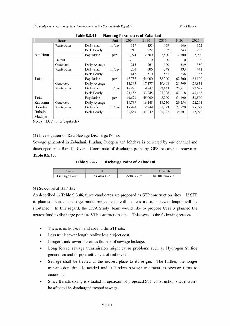
The study on sewerage system development in the Syrian Arab Republic Final Report
M9-111
Table 9.5.44 Planning Parameters of Zabadani Items Unit 2004 2010 2015 2020 2025 Wastewater Daily max m3/day 127 133 139 146 152 Peak Hourly 211 222 232 243 253Ain Hour Population per. 1,974 2,300 2,500 2,700 2,900 Tourist % 0 0 0 0 Generated Daily Average 215 264 300 339 380 Wastewater Daily max m3/day 250 306 348 393 441 Peak Hourly 417 510 581 656 735Total Population per. 47,737 54,000 58,700 62,700 66,100 Generated Daily Average 14,545 17,177 19,498 21,709 23,851 Wastewater Daily max m3/day 16,891 19,947 22,643 25,211 27,698 Peak Hourly 28,152 33,245 37,738 42,018 46,163Total Population per. 40,623 45,000 48,300 51,100 53,500Zabadani Generated Daily Average 13,769 16,145 18,250 20,254 22,201Bloudan Wastewater Daily max m3/day 15,990 18,749 21,193 23,520 25,782Bukein Peak Hourly 26,650 31,249 35,322 39,201 42,970Madaya
Note) LCD : liter/capita/day (3) Investigation on Raw Sewage Discharge Points Sewage generated in Zabadani, Bludan, Buqqein and Madaya is collected by one channel and discharged into Barada River. Coordinate of discharge point by GPS research is shown in Table 9.5.45:
Table 9.5.45 Discharge Point of Zabadani
Name N E Diameter Discharge Point 33°40′43.9″ 36°04′33.8″ Dia. 800mm x 2
(4) Selection of STP Site As described in Table 9.5.46, three candidates are proposed as STP construction sites. If STP is planned beside discharge point, project cost will be less as trunk sewer length will be shortened. In this regard, the JICA Study Team would like to propose Case 3 planned the nearest land to discharge point as STP construction site. This owes to the following reasons:
• There is no house in and around the STP site. • Less trunk sewer length realize less project cost. • Longer trunk sewer increases the risk of sewage leakage. • Long forced sewage transmission might cause problems such as Hydrogen Sulfide
generation and in-pipe settlement of sediments. • Sewage shall be treated at the nearest place to its origin. The further, the longer
transmission time is needed and it hinders sewage treatment as sewage turns to anaerobic.
• Since Barada spring is situated in upstream of proposed STP construction site, it won’t be affected by discharged treated sewage.

The study on sewerage system development in the Syrian Arab Republic Final Report
M9-112
Table 9.5.46 Comparison of Proposed STP Sites
Items Case 1 Case 2 Case 3 1. Proposed by EIB MHC The JICA Study Team 2. Location Located at downstream of
Study Area. Orchard in right bank of Barada River.
Located at downstream of Study Area. Hilly area 800 m away from right bank of Barada River. Near to discharge point compared with Case 1.
Land 400 m away from discharge point.
3. Sewage transmission measure
Trunk sewer with length of 6 km and pumping station to cross the river is needed.
Trunk sewer length is shorter than Case1 by 1.8 km. As STP site has high elevation, PS is needed to transmit sewage to STP.
As STP site is close to discharge point, trunk sewer length is the shortest. No PS is needed.
4. Surrounding Environment
As surrounding is orchard and there are no housings. As located near to Barada River, groundwater level is high and ground is soft.
There are no housings in surrounding. Ground is quite firm. Since ground is uneven, grading work is needed.
There is trunk road and housings near to STP site. Barada spring is located 2 km in the west.
Location of the proposed STP site (Zabadani) is shown in Table 9.5.47:
Table 9.5.47 Location of the Proposed STP Site (Zabadani)
Site N E Level Land-use Land Cost(SP/m2)
Land Owner
Distance from residential area
No.1 STP Site 33°38′39.9″ 36°04′13.0″ 1093 Farm land 2,000 Private 150m No.2 STP Site 33°37′37.9″ 36°04′17.0″ 1149 Not used 500 Private 200m
No.3 STP Site 33°40′39.9″ 36°04′37.5″ 1110 Ministry of Irrigation - Public 100m
(5) Sewage Collection Plan 1) Trunk Sewer Plan Currently, installation work of trunk sewer is on-going in Zabadani City. The jurisdiction of Zabadani City is within city boundary and outside of it shall be managed by Buqqein and Madaya located in downstream. Therefore, most of trunk sewer is about to be completed. Diversion chamber shall be installed in upstream of discharge point to send sewage to STP. Refer to Table 9.5.48.
Table 9.5.48 Design of Trunk Sewer
Flow rate Capacity Diameter Gradient v Q m3/day m3/s m3/s mm ‰ m/s m3/s 42,970 0.497 0.994 800 3.4 1.99 1.002
Transmission trunk sewer length is 100 m approximately stated from the diversion chamber to

The study on sewerage system development in the Syrian Arab Republic Final Report
M9-113
pumping station at STP. (6) Sewage Treatment Plant Plan
1) Incoming Sewage Quality and Effluent Standard Treated sewage will be discharged to Barada River trough a creek. As the contamination of groundwater has been increasing in Rural Damascus Governorate, effluence standard in Zabadani shall be set up so as to enable the re-use of treated sewage to irrigate vegetable farms. However, if treated sewage is to be discharged into river, standard of SS 30 mg/l shall be applied. It is stringent than 50 mg/l applied in case of irrigation use for vegetable. Refer to Table 9.5.49.
Table 9.5.49 Incoming Sewage Quality and Effluent Standard
Discharge mode to water-body
/ Condition of re-useMaximum allowed effluent standard from STP (mg/l)
Items
Indices BOD SS NH3-N NO3-N T-N T-P Incoming Sewage
310 360 74 24
Irrigation (vegetable) 30 50 3 20 Effluent Standard River 40 30 5 50 Proposed effluent
standard 30 30 3 20
2) Summary of Conditions and Facilities The conditions considered for Planning and information on proposed facilities are listed in Table 9.5.50.
Table 9.5.50 Summary of Conditions and Proposed Facilities
Items Contents Daily Average Sewage Flow (m3/d) 22,201 Hourly Maximum Sewage Flow (m3/d) 42,970 Sludge (kgDS/d) 5,495 Sludge (m3/d) 27.5 Moisture content (%) 80 Treatment processes OD Gravel Thickener + Mechanical dewatering
Grit chamber (No.-w×L) 2-1.6m×8m Main P (No.-D×power) 5-φ250mm×15kw
Reactor (No.-W×L×H) 10-5.5m×150m×5m
Final sedimentation tank 8-φ18m Disinfection channel 3-1.5m×3.5m×0.8m (UV) Gravity Sludge Thickener 2-6.0m×6.0m Mechanical Sludge Dehydrator 2-2,747kg/d
Required land area (ha) 5.5
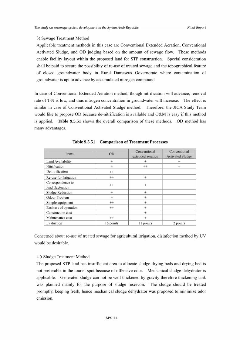
The study on sewerage system development in the Syrian Arab Republic Final Report
M9-114
3) Sewage Treatment Method Applicable treatment methods in this case are Conventional Extended Aeration, Conventional Activated Sludge, and OD judging based on the amount of sewage flow. These methods enable facility layout within the proposed land for STP construction. Special consideration shall be paid to secure the possibility of re-use of treated sewage and the topographical feature of closed groundwater body in Rural Damascus Governorate where contamination of groundwater is apt to advance by accumulated nitrogen compound.
In case of Conventional Extended Aeration method, though nitrification will advance, removal rate of T-N is low, and thus nitrogen concentration in groundwater will increase. The effect is similar in case of Conventional Activated Sludge method. Therefore, the JICA Study Team would like to propose OD because de-nitrification is available and O&M is easy if this method is applied. Table 9.5.51 shows the overall comparison of these methods. OD method has many advantages.
Table 9.5.51 Comparison of Treatment Processes
Items OD Conventional
extended aeration Conventional
Activated Sludge Land Availability + + + Nitrification + ++ + Denitrification ++ Re-use for Irrigation ++ + Correspondence to load fluctuation
++ +
Sludge Reduction + + Odour Problem + + Simple equipment ++ + Easiness of operation ++ + Construction cost + Maintenance cost ++ + Evaluation 16 points 11 points 2 points
Concerned about re-use of treated sewage for agricultural irrigation, disinfection method by UV would be desirable.
4)Sludge Treatment Method The proposed STP land has insufficient area to allocate sludge drying beds and drying bed is not preferable in the tourist spot because of offensive odor. Mechanical sludge dehydrator is applicable. Generated sludge can not be well thickened by gravity therefore thickening tank was planned mainly for the purpose of sludge reservoir. The sludge should be treated promptly, keeping fresh, hence mechanical sludge dehydrator was proposed to minimize odor emission.
The study on sewerage system development in the Syrian Arab Republic Final Report
M9-115
* Sludge treatment is an early field of technical innovation. As an example, adoption of the "multiplex board type screw press dehydrator" which enabled continuous and efficient processing by withdrawing low concentration sludge directly from a reactor is generalized in small-scale STP, such as the Oxidation Ditch method in Japan. The adoption of this dehydrator can omit a thickening process and a storage tank, and has a merit, like control of maintenance becomes easy. In a design phase, it is important to discern the trend of sludge treatment technology well, to take into consideration economical efficiency, control of maintenance, marketability, etc., and to select a sludge treatment flow.
5) Special Consideration on Facility Planning • There are some issues that need consideration while preparing plan:
a) The population of tourist is uncertain. b) Actual condition on water consumption is not defined. c) Agricultural effluent or spring has possibly to be contained in sewage.
As we could not figure out the entire actual conditions through our survey in short period, layout plan in Appendix is planned based on design conditions established by the JICA Study Team. To cope with future incoming pollution load fluctuation, land required for expansion is secured. • As current effluent standard is too stringent in terms of NH3-N concentration,
stabilization pond is planned upstream of discharge point for keeping in mind safety. This would become landscape pond to raise fishes, and ecological pond for environmental education as well.
Master plan of Zabadani is shown in Figure 9.5.24:

The study on sewerage system development in the Syrian Arab Republic Final Report
M9-116
Figure 9..5.24 Master Plan of Zabadani

The study on sewerage system development in the Syrian Arab Republic FinalReport
M9-117
9.6 Summary of the Proposed Sewerage Facilities
9.6.1 Proposed Sewerage Facilities
The JICA Study Team proposed sewerage facilities for seven designated M/P areas based on careful investigation on the existing sewerage facilities, topographic condition, availability of STP construction land and locally available O&M skill. The outline of proposed sewerage facilities are shown in Table 9.6.1. Trunk sewer covers from existing discharge points to STP.
Table 9.6.1 Proposed Sewerage Facilities in Seven Designated Areas
M/P Areas Items Facilities Quantity Remarks Slunfeh/ Pipe D 250 2,700 m No.1DP – No.1 STP
D 250 1,600 m No.3DP – No.2 STP D 250 3,600 m No.6DP – No.3 STP Total 7,900 m D 100 500 m No.5 DP D 100 500 m No.8 DP Total 1,000 m Pumping Station 0.5 m3/min 2 No.5,8 DP
Incoming Flow 610 m3/day×3 3 STPS
Lattkia
Treatment Method
Submerged attached method
STP
Site Area 0.1 ha ×3 3 STPs Pipe D 250 1,800 m From Tero First phase D 250 1,300 m From Kharbet Snasel D 250 1,600 m From Al-Najor
Banias/ Tartous
D 300 580 m Gravity D 250 140 m Pressure D 300 550 m Pressure D 400 770 m Pressure D 500 1,820 m Pressure D 600 2,310 m Pressure Second phase D 250 140 m Pressure D 300 550 m Pressure D 400 770 m Pressure D 500 1,820 m Pressure D 600 2,310 m Pressure Manhole Pump 3.0 m3/min 4×2 (First phase, Second
phase) 1.0 m3/min 5×2 (First phase, Second
phase) STP Incoming Flow 19,556 m3/day Treatment
Method Oxidation Ditch
Site Area 5.1 ha Mayadin/ Pipe D 400 3,500m
D 800 1,000m Incoming Flow 15,300 m3/day STP
Deir-Ez-zor
Treatment Method
Oxidation Ditch
Site Area 5.9 ha Malkieh/ Pipe D 500 100 m diversion device –STP Hassakeh Incoming Flow 4,518 m3/day Treatment
Method Oxidation Ditch
STP
Site Area 2.6 ha Thawra/ Pipe D 500 100 m No.3 – STP Raqqa D 600 1,300 m No.2,3 – STP Incoming Flow 17,889 m3/day
STP Treatment Constructed

The study on sewerage system development in the Syrian Arab Republic FinalReport
M9-118
Table 9.6.1 Proposed Sewerage Facilities in Seven Designated Areas M/P Areas Items Facilities Quantity Remarks
Method Wet Land Site Area 2.4 ha Muzerib/ Pipe D 400 5,800 m Dar’aa D 500 4,000 m Incoming Flow 3,994 m3/day Treatment
Method Constructed
Wet Land
STP
Site Area 4.9 ha Zabadani/ Pipe D 800 100 m diversion device –STP Rural Damascus
STP Incoming Flow 22,201 m3/day
Treatment Method
Oxidation Ditch
Site Area 5.5 ha Note) D : Diameter (mm), DP : Discharge point
9.6.2 Treatment Methods and Major Effluent Regulations
Table 9.6.2 shows the proposed sewage and sludge treatment methods employed in each STP in seven target areas. Syrian effluent standards according to the types of receiving water bodies and to the usage of treated sewage are also described.
Table 9.6.2 Proposed Treatment Methods and Major Effluent Regulations
Maximum allowed effluent standard from STP (mg/l)
M/P Area Situations of STP site and Sewage Treatment Method
Sludge Treatment Method
BOD SS NH3-N NO3-N
Discharge to River Slunfeh/ Lattakia
Three STP lands are allocated in mountainous tourist spot. Each plant capacity is 500 m3/d. As proposed plant capacity is small, Submerged Attached Growth Method generally adopted to on-site facility in Japan was proposed as this facility needs no daily O&M. Weekly O&M is sufficient to maintain treatment function. Treated wastewater discharged to valley reaches to two dams located 20 to 28 km away. Dam water has not been polluted.
Small amount of sludge peeled from bio-film shall be conveyed to Lattakia STP by tanker.
40 30 5 50
Discharge to Sea Banias/ Tartous
As proposed STP construction site is supposed to be urban area in the future, OD requires easy O&M and no primary settling tank generates offensive odor, was proposed.
As stated, offensive odor must be minimized. Mechanical sludge dewatering unit was proposed.
60 60 10 50
Discharge to River Mayadin/ Deir-Ez-zor
STP was planned in the midst of public owned farmland. Receiving water body has big environment capacity. OD needs easier O&M was proposed.
Proposed STP site has enough area but sludge can not be thickened by gravity. Mechanical Thickening and Drying Bed was proposed
40 30 5 50
Malkieh/ Hassakeh
All methods are applicable as proposed STP construction site has vast area. OD was
Proposed STP site has enough area but sludge can
Discharge to River / Irrigation for cotton

The study on sewerage system development in the Syrian Arab Republic FinalReport
M9-119
Table 9.6.2 Proposed Treatment Methods and Major Effluent Regulations
Maximum allowed effluent standard from STP (mg/l)
M/P Area Situations of STP site and Sewage Treatment Method
Sludge Treatment Method
BOD SS NH3-N NO3-N
proposed to satisfy the effluent standard, to preserve water resources. Easiness in O&M was another reason of adoption.
not be thickened by gravity. Mechanical Thickening and Drying Bed was proposed
40 30 5 50
Discharge to River Thawra/ Raqqa
There is well performed reed beds spread about 2 km’s long. Wet-land was proposed to optimize the existing facility. To cope with future population growth, pre-treatment facility - primary settling tank- supporting the existing reed beds shall be installed.
Though generated sludge is not digested, Sludge Drying Bed was proposed due to the economical efficiency.
40 30 5 50
Discharge to River Muzerib/ Dar’aa
STP was planned in private farm land. As pollution in water resource (well), has not been reported, Wet-land was proposed in terms of improvement of water environment of water body and lowering of financial burden.
Ditto
40 30 5 50
Irrigation/ Discharge to River Zabadani/ Rural Damascus
STP was proposed in public land of 5.5ha in the midst of farm land. OD was proposed in terms of mitigation of nitrogen contained in water within Barada river basin, efficient and safe irrigation purpose use and easiness in O&M.
Considering the odor issue, proposed site area is not enough for drying bed. Mechanical Dewatering were proposed.
30 30 3 20
9.6.3 Design Criteria and Major Facilities
Table 9.6.3 indicates design criteria, structural dimension of major facilities and specifications of major equipment.
Table 9.6.3 Design Criteria and Major Facilities Slunfeh Banias Mayadin Malkieh Thawra Muzerib Zabadani
Average flow (m3/d) 1,833 19,556 15,300 4,518 17,889 3,994 22,201Hourly max (m3/d) 3,548 37,851 29,610 8,744 34,625 7,730 42,970Sludge (kgDS/d) 224 4,401 3,787 1,119 2,361 527 5,495Sludge (m3/d) 2.7 22.0 9.5 2.8 5.9 1.3 27.5Moisture content (%) 92 80 60 60 60 60 80 No. of STP 3 1 1 1 1 1 1
Treatment method Submerged attached growth
OD OD OD Wet-land Wet-land OD
Grit chamber (No.-w×L) Each 1-1×1m 2-1.5×7m 2-1.4×6m 1-1.3×4.0m 2-1.3×7.5m 1-0.9×5m 2-1.6×8m
Main pump (No.-D×power)
- - 5-φ200mm ×11kw
3-φ150mm ×3.7kw
5-φ250mm ×11kw
3-φ150mm ×5.5kw
5-φ250mm ×15kw
Primary settling tank 4-φ10 2-φ6.5m Reed bed 24-21m×37mReactor (No.-W×L×H) Each
2-5.5×12 ×5m 12-4.5 ×140× 3.0m/ high rate
8-4.5 ×140×3.0m/high rate
4-4.5 ×140×3.0m
10-5.5 ×150 ×5m
Final sedimentation tank Each 8-φ18m 8-φ15m 4-φ11m 8-φ18m

The study on sewerage system development in the Syrian Arab Republic FinalReport
M9-120
Table 9.6.3 Design Criteria and Major Facilities Slunfeh Banias Mayadin Malkieh Thawra Muzerib Zabadani
2-5.5×3m Disinfection channel (No.-W×L×H)
Each 1-φ0.9m 2-2×24×2.1m 2-2×21×1.9m 1-0.9×3.5×0.8m (UV)
3-1.5×3.5×0.8m (UV)
Gravity thickener (No-kg/d)
2-5.0×5.0 2-6.0×6.0
Mechanical thickener (No-kg/d)
2-1,893 1-1,119
Mechanical dehydrator (No-kg/d)
2-2,201 2-2,747
Drying bed (No.-W×L)
24-15×43m 8-15×38m 20-15×32m 8-12×22m
Required land area (ha) Each 0.1 5.1 5.9 2.6 2.4 4.9 5.5
Land owner Public/ Private
Private Public Public Public Private Public
Source: Japanese Sewerage System Standard as to sludge moisture content
9.6.4 Maps for Sewerage Master Plan
Master plans for seven prioritized cities in seven Governorates were prepared in this study. The Study Team dully aware that master plan for other prioritized cities shall also be established by Syrian side utilizing design procedures shown in this study. Therefore, the Study Team prepared maps showing the locations of STPs in seven governorates. These maps were prepared as reference data to plan STPs for cities with considerable population in 2025 and where sewer network have already been developed. Maps are shown in Figure 9.6.1 to 9.6.7. Population range by sub-district was indicated by different colors and STP locations, the following legend of STPs and STP list were described in the maps:
LEGEND Proposed STP ● Existing STP ● STP under Construction ● STP under Study ●
No. Name of STP Population to be served in 2025
Design Plant Capacity (m3/day)
Current Status
1 A STP 20,000 Proposed 2 B STP 1,000 Existing 3 C STP 2,500 Under Construction 4 D STP 1,400 Under Study
JICA Study Team prepared the following Maps: • Large Governorate-wise Map showing STP location and STP List Size = A2 • Detailed City-wise Map showing the boundary of service area Size = A4

The study on sewerage system development in the Syrian Arab Republic FinalReport
M9-121
The Study Team proposed the following criteria in STP planning prioritization:
Table 9.6.4 Proposed Criterion on STP Planning Prioritization Criteria Prioritization Order (Existing STP) Shall be excluded from priority order STP under Construction Shall be given the highest priority order and if there are plural STPs
under Construction, their order shall be determined by design plant capacity. The greater, the higher.
STP under Study Shall be given 2nd highest priority order and if there are plural STPs under Study, their order shall be determined by design plant capacity. The greater, the higher.
Proposed STP Shall be given 3rd highest Priority Order and if there are plural proposed STPs, their order shall be determined by served population. The greater, the higher.
Of course the Study Team dully aware that there must be another factors to be considered:
Table 9.6.5 Another Factors to be considered upon STP Planning Prioritization Factors Prioritization Order Sanitary Condition in target area including odor problem, drinking water quality and morbidity of water-borne disease.
The poorer, the greater order
Water quality in receiving public Water bodies
The worse, the greater order
As the detailed topographic map was not available, the Study Team prepared “Detailed City-wise Map” utilizing Google Map Information. However, STP location shown in the said map was proposed by the Study Team without detailed information on topographic condition, location of existing trunk sewer and wastewater discharging points, land availability of STP site, modification shall be made based on the abovementioned information. Since these maps were prepared as reference data for future STP planning, the Study Team consolidated them as reference data apart from official report. As to maps prepared by the Study Team, refer to Sewerage Master Plan Maps. The following is the list of detailed City-wise Map.
Table 9.6.6 List of detailed City-wise Map Governorate Area Population Remarks
No 1: Jableh 54,500 Lattakia No 2: Al Qurdaha 10,100 No 1: Banias 85,600 No 2: Drekiesh 13,800
Tartous
No 3: Al Shiekh Bader 9,800 No 1: Mo Hasan 12,400 No 2: Al Bu-Lail 13,100
No 1+No 2 (integrated service area)
No 3: Abu Kamal 64,900 No 4: Hajeen 51,100
Deir-Ez-zor
No 5: Gharaneej 15,500

The study on sewerage system development in the Syrian Arab Republic FinalReport
M9-122
Table 9.6.6 List of detailed City-wise Map Governorate Area Population Remarks
No 6: Sha’afah 14,600 No 7: Bogros Tahtani 12,100 No 8: Mhagan 15,800 No 12: Mayadin 14,100
No 8+No 12 (integrated service area)
No 9: Asharah 21,900 No 11: Qorieh 35,200
No 9+No 11 (integrated service area)
No 10: Sbekhan 25,600 No 1: Al-Shadadi 22,500 No 2: Qamishli 214,400 No 3: Amoda 24,700 No 4: Al-Kahtanieh 10,900 No 5: Al-Moua’abadeh 18,900 No 6: Al Derbasieh 11,600
Hassakeh
No 8: Malkieh 34,500 Raqqa No 1: Thawra 115,600
No 1: Tafas 43,100 No 2: Al Ghariya Al Sharkiya 14,600 No 3: Al Harah 16,400 No 4: Enkhel 29,800 No 5: Kherbet Ghazal 33,000 No 6: Al Jyza 24,200
Dar’aa
No 7: Harrak 36,100 No 4: Saieda Zeinab 238,500 No 34: Daria 167,800 No 35: Modamiet Al Cham 84,300 No 37: Ashrafiet Sahnaya 35,200 No 43: Artouz 40,000
No 34+No 35+No 37+No 43 (integrated service area)
No 46: Kanaker 19,200 No 47: Sasa 12,200
No 46+No 47 (integrated service area)
No 49: Al Qotifeh 32,200 No 51: Mo’damiet Al Kalamout
18,200
Rural Damascus
No 53: Al Rhaibe 47,000
No 49+No 51+No 53 (integrated service area)
STP lists of seven Governorates are shown in Table 9.6.7 to Table 9.6.13. It’s noteworthy that “Priority Order” shown in the said tables was proposed by the Study Team based on “proposed criterion on STP planning prioritization” shown in Table 9.6.4.
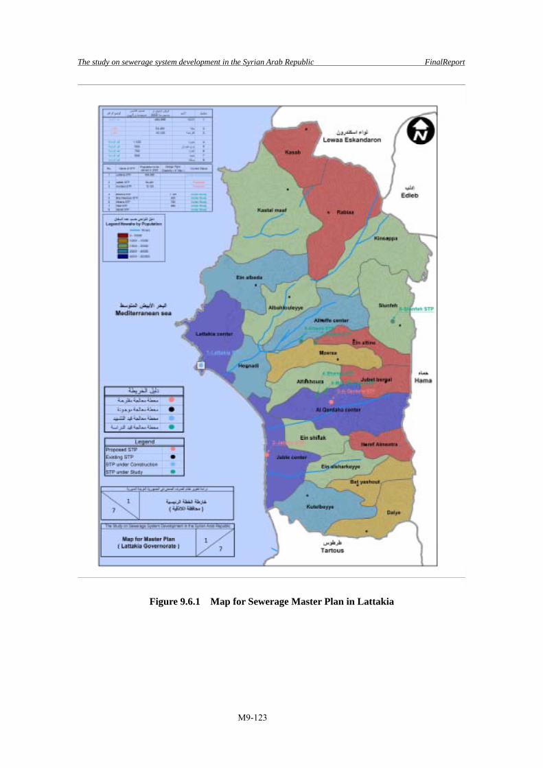
The study on sewerage system development in the Syrian Arab Republic FinalReport
M9-123
Figure 9.6.1 Map for Sewerage Master Plan in Lattakia
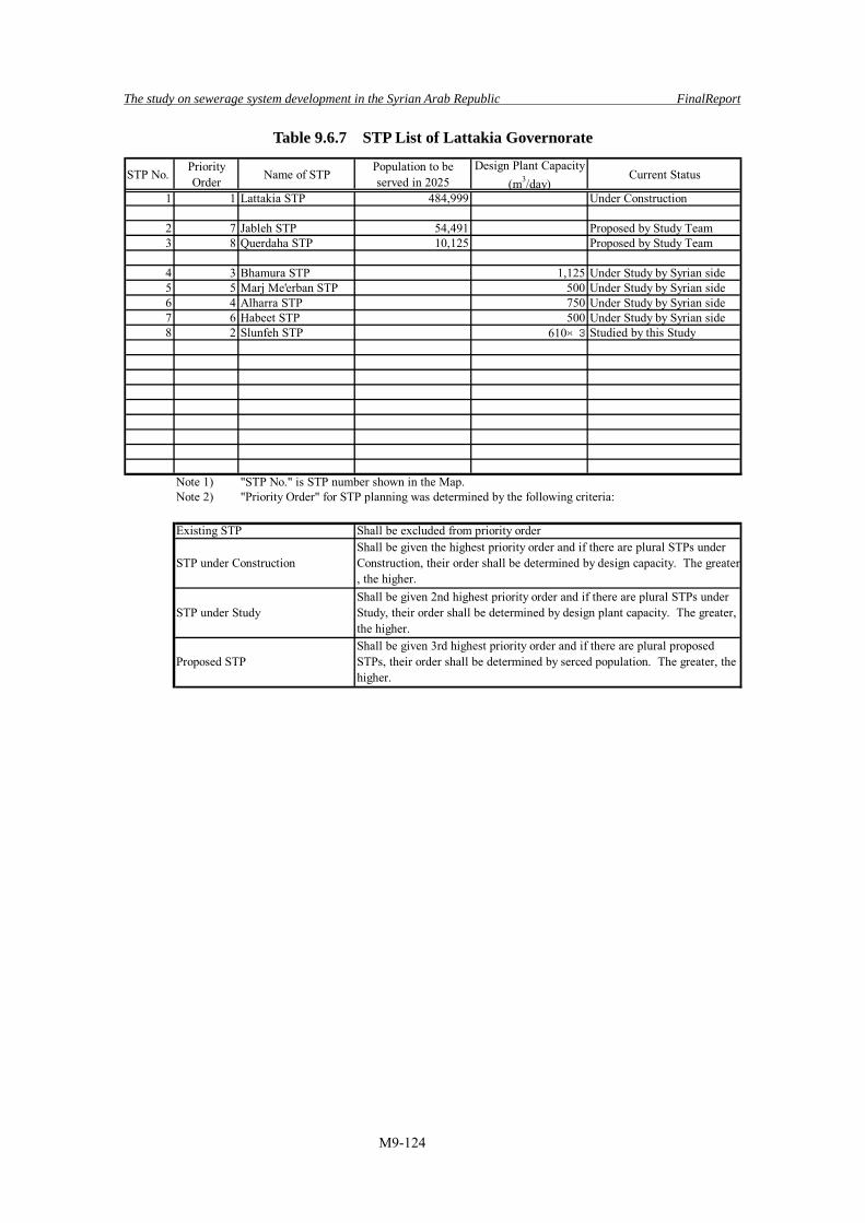
The study on sewerage system development in the Syrian Arab Republic FinalReport
M9-124
Table 9.6.7 STP List of Lattakia Governorate
STP No.PriorityOrder Name of STP
Population to beserved in 2025
Design Plant Capacity(m3/day)
Current Status
1 1 Lattakia STP 484,999 Under Construction
2 7 Jableh STP 54,491 Proposed by Study Team3 8 Querdaha STP 10,125 Proposed by Study Team
4 3 Bhamura STP 1,125 Under Study by Syrian side5 5 Marj Me'erban STP 500 Under Study by Syrian side6 4 Alharra STP 750 Under Study by Syrian side7 6 Habeet STP 500 Under Study by Syrian side8 2 Slunfeh STP 610×3 Studied by this Study
Note 1) "STP No." is STP number shown in the Map.Note 2) "Priority Order" for STP planning was determined by the following criteria:
Proposed STPShall be given 3rd highest priority order and if there are plural proposedSTPs, their order shall be determined by serced population. The greater, thehigher.
Existing STP
STP under Construction
STP under StudyShall be given 2nd highest priority order and if there are plural STPs underStudy, their order shall be determined by design plant capacity. The greater,the higher.
Shall be excluded from priority orderShall be given the highest priority order and if there are plural STPs underConstruction, their order shall be determined by design capacity. The greater, the higher.
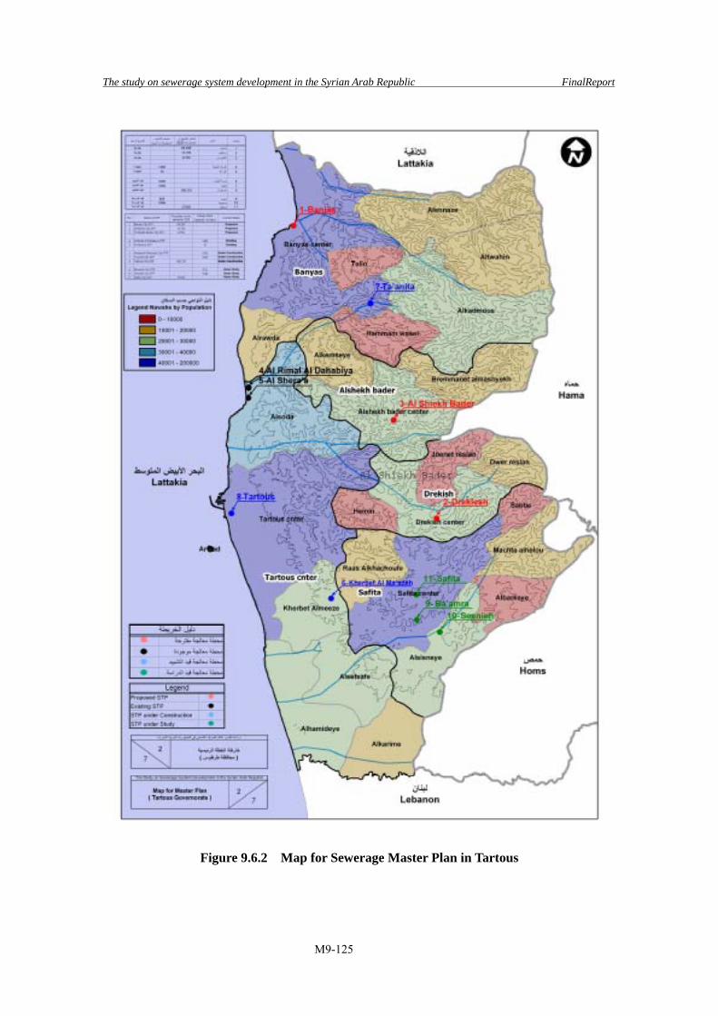
The study on sewerage system development in the Syrian Arab Republic FinalReport
M9-125
Figure 9.6.2 Map for Sewerage Master Plan in Tartous
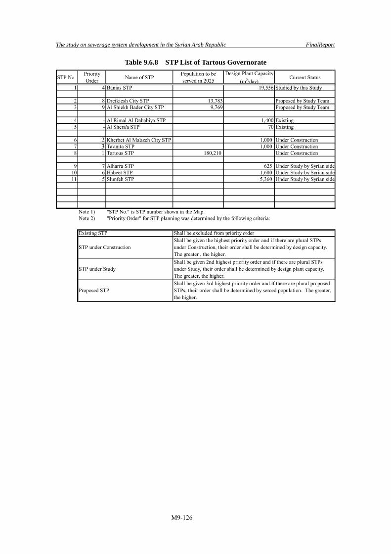
The study on sewerage system development in the Syrian Arab Republic FinalReport
M9-126
Table 9.6.8 STP List of Tartous Governorate
STP No.PriorityOrder Name of STP
Population to beserved in 2025
Design Plant Capacity(m3/day)
Current Status
1 4 Banias STP 19,556 Studied by this Study
2 8 Dreikiesh City STP 13,783 Proposed by Study Team3 9 Al Shiekh Bader City STP 9,769 Proposed by Study Team
4 - Al Rimal Al Dahabiya STP 1,400 Existing5 - Al Shera'a STP 70 Existing
6 2 Kherbet Al Ma'azeh City STP 1,000 Under Construction7 3 Ta'anita STP 1,000 Under Construction8 1 Tartous STP 180,210 Under Construction
9 7 Alharra STP 625 Under Study by Syrian side10 6 Habeet STP 1,680 Under Study by Syrian side11 5 Slunfeh STP 5,360 Under Study by Syrian side
Note 1) "STP No." is STP number shown in the Map.Note 2) "Priority Order" for STP planning was determined by the following criteria:
Proposed STPShall be given 3rd highest priority order and if there are plural proposedSTPs, their order shall be determined by serced population. The greater,the higher.
Existing STP
STP under Construction
STP under StudyShall be given 2nd highest priority order and if there are plural STPsunder Study, their order shall be determined by design plant capacity.The greater, the higher.
Shall be excluded from priority orderShall be given the highest priority order and if there are plural STPsunder Construction, their order shall be determined by design capacity.The greater , the higher.

The study on sewerage system development in the Syrian Arab Republic FinalReport
M9-127
Figure 9.6.3 Map for Sewerage Master Plan in Deir-Ez-zor

The study on sewerage system development in the Syrian Arab Republic FinalReport
M9-128
Table 9.6.9 STP List of Deir-Ez-zor Governorate
STP No.PriorityOrder Name of STP
Population to beserved in 2025
Design Plant Capacity(m3/day)
Current Status
1 12 Mo Hassan STP 12,425 Proposed by Study Team2 11 Al Bu-Lail STP 13,102 Proposed by Study Team3 3 Abu Kamal STP 64,935 Proposed by Study Team4 4 Hajeen STP 51,145 Proposed by Study Team5 9 Gharaneej STP 15,511 Proposed by Study Team6 10 Sha'afah STP 14,551 Proposed by Study Team7 13 Bogros Taftani STP 12,125 Proposed by Study Team8 8 Mhagan STP 15,802 Proposed by Study Team9 7 Asharah STP 21,917 Proposed by Study Team
10 6 Sbekhan STP 25,567 Proposed by Study Team11 5 Qorieh STP 35,209 Proposed by Study Team
12 2 Mayadin STP 15,300 Studied by this Study13 1 Deir-Ez-zor STP 67,850 Under Study by Syrian side
Note 1) "STP No." is STP number shown in the Map.Note 2) "Priority Order" for STP planning was determined by the following criteria:
Proposed STPShall be given 3rd highest priority order and if there are plural proposedSTPs, their order shall be determined by serced population. The greater,the higher.
Existing STP
STP under Construction
STP under StudyShall be given 2nd highest priority order and if there are plural STPsunder Study, their order shall be determined by design plant capacity.The greater, the higher.
Shall be excluded from priority orderShall be given the highest priority order and if there are plural STPsunder Construction, their order shall be determined by design capacity.The greater , the higher.

The study on sewerage system development in the Syrian Arab Republic FinalReport
M9-129
Figure 9.6.4 Map for Sewerage Master Plan in Hassakeh
Figure 9.6.5 Map for Sewerage Master Plan in Raqqa
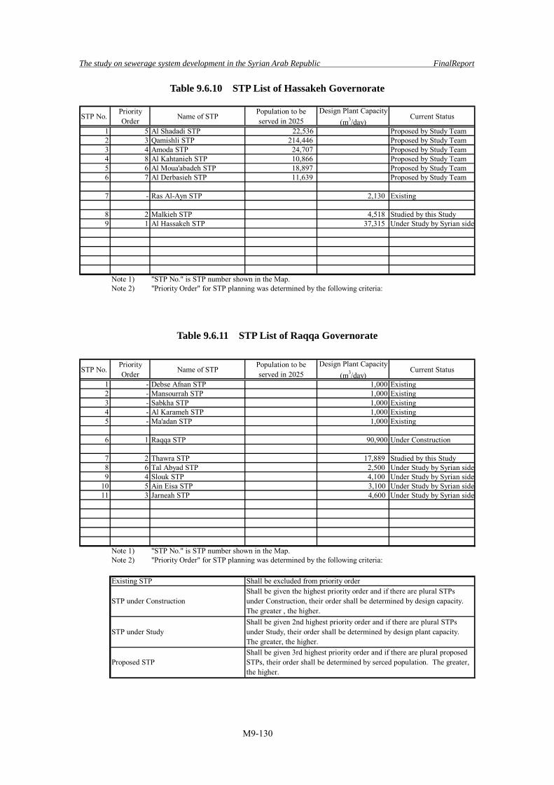
The study on sewerage system development in the Syrian Arab Republic FinalReport
M9-130
Table 9.6.10 STP List of Hassakeh Governorate
STP No.PriorityOrder Name of STP
Population to beserved in 2025
Design Plant Capacity(m3/day)
Current Status
1 5 Al Shadadi STP 22,536 Proposed by Study Team2 3 Qamishli STP 214,446 Proposed by Study Team3 4 Amoda STP 24,707 Proposed by Study Team4 8 Al Kahtanieh STP 10,866 Proposed by Study Team5 6 Al Moua'abadeh STP 18,897 Proposed by Study Team6 7 Al Derbasieh STP 11,639 Proposed by Study Team
7 - Ras Al-Ayn STP 2,130 Existing
8 2 Malkieh STP 4,518 Studied by this Study9 1 Al Hassakeh STP 37,315 Under Study by Syrian side
Note 1) "STP No." is STP number shown in the Map.Note 2) "Priority Order" for STP planning was determined by the following criteria:
Table 9.6.11 STP List of Raqqa Governorate
STP No.PriorityOrder Name of STP
Population to beserved in 2025
Design Plant Capacity(m3/day)
Current Status
1 - Debse Afnan STP 1,000 Existing2 - Mansourrah STP 1,000 Existing3 - Sabkha STP 1,000 Existing4 - Al Karameh STP 1,000 Existing5 - Ma'adan STP 1,000 Existing
6 1 Raqqa STP 90,900 Under Construction
7 2 Thawra STP 17,889 Studied by this Study8 6 Tal Abyad STP 2,500 Under Study by Syrian side9 4 Slouk STP 4,100 Under Study by Syrian side
10 5 Ain Eisa STP 3,100 Under Study by Syrian side11 3 Jarneah STP 4,600 Under Study by Syrian side
Note 1) "STP No." is STP number shown in the Map.Note 2) "Priority Order" for STP planning was determined by the following criteria:
Proposed STPShall be given 3rd highest priority order and if there are plural proposedSTPs, their order shall be determined by serced population. The greater,the higher.
Existing STP
STP under Construction
STP under StudyShall be given 2nd highest priority order and if there are plural STPsunder Study, their order shall be determined by design plant capacity.The greater, the higher.
Shall be excluded from priority orderShall be given the highest priority order and if there are plural STPsunder Construction, their order shall be determined by design capacity.The greater , the higher.

The study on sewerage system development in the Syrian Arab Republic FinalReport
M9-131
Figure 9.6.6 Map for Sewerage Master Plan in Dar’aa

The study on sewerage system development in the Syrian Arab Republic FinalReport
M9-132
Table 9.6.12 STP List of Dar'aa Governorate
STP No.PriorityOrder Name of STP
Population to beserved in 2025
Design Plant Capacity(m3/day)
Current Status
1 10 Tafas STP 43,078 Proposed by Study Team2 16 Al Ghariya Al Sharkiya STP 14,555 Proposed by Study Team3 15 Al Harah STP 16,376 Proposed by Study Team4 13 Enkhel STP 29,808 Proposed by Study Team5 12 Kherbet Ghazal STP 32,982 Proposed by Study Team6 14 Al Jyza STP 24,203 Proposed by Study Team7 11 Harrak STP 36,121 Proposed by Study Team
8 Naseeb STP 200 Existing
9 2 Da'el STP 16,000 Under Construction10 1 Dar'aa STP 21,800 Under Construction
11 8 Muzerib STP 3,994 Studied by this Study12 4 Bosra Al Cham STP 7,800 Under Study by Syrian side13 5 Jasem STP 6,500 Under Study by Syrian side14 7 Nawa STP 5,500 Under Study by Syrian side15 6 Shiek Mskeen STP 6,500 Under Study by Syrian side16 9 Tseel STP 3,000 Under Study by Syrian side17 3 Al Sanameen STP 8,500 Under Study by Syrian side
Note 1) "STP No." is STP number shown in the Map.Note 2) "Priority Order" for STP planning was determined by the following criteria:
Proposed STPShall be given 3rd highest priority order and if there are plural proposedSTPs, their order shall be determined by serced population. The greater,the higher.
Existing STP
STP under Construction
STP under StudyShall be given 2nd highest priority order and if there are plural STPsunder Study, their order shall be determined by design plant capacity.The greater, the higher.
Shall be excluded from priority orderShall be given the highest priority order and if there are plural STPsunder Construction, their order shall be determined by design capacity.The greater , the higher.

The study on sewerage system development in the Syrian Arab Republic FinalReport
M9-133
Figure 9.6.7 Map for Sewerage Master Plan in Rural Damascus

The study on sewerage system development in the Syrian Arab Republic FinalReport
M9-134
Table 9.6.13 (1/2) STP List of Rural Damascus Governorate
STP No.PriorityOrder Name of STP
Population to beserved in 2025
Design Plant Capacity(m3/day)
Current Status
1 21 Babyla STP 89,420 Proposed by Study Team2 32 Yalda STP 44,900 Proposed by Study Team3 48 Hajeera STP 21,670 Proposed by Study Team4 16 Saieda Zeinab STP 238,490 Proposed by Study Team5 22 Sbene STP 87,890 Proposed by Study Team6 20 Keswe STP 116,500 Proposed by Study Team7 61 Mkilbieh STP 12,790 Proposed by Study Team8 67 A'deliya STP 11,900 Proposed by Study Team9 75 Darkhabien STP 10,500 Proposed by Study Team
10 68 Adlieh STP 11,900 Proposed by Study Team11 56 Dyer Ali STP 16,660 Proposed by Study Team12 45 8th of March STP 25,470 Proposed by Study Team13 39 Zakieh STP 30,340 Proposed by Study Team14 76 Bait Sawa STP 10,140 Proposed by Study Team15 52 Hammoura STP 17,860 Proposed by Study Team16 58 Sabrin STP 15,450 Proposed by Study Team17 66 Hazzwh STP 12,060 Proposed by Study Team18 26 Ain Tarma STP 57,950 Proposed by Study Team19 34 Sabkba STP 41,680 Proposed by Study Team20 18 Jaramana STP 134,910 Proposed by Study Team21 27 Arbeen STP 57,360 Proposed by Study Team22 30 Zamalka STP 48,010 Proposed by Study Team23 77 Htietet Al-Turkman STP 6,820 Proposed by Study Team24 63 Dier Al-Asafir STP 12,530 Proposed by Study Team25 57 Zabdin STP 16,130 Proposed by Study Team26 28 Htietet Al-Turkman STP 52,820 Proposed by Study Team27 43 Housh Al-Soltan STP 27,750 Proposed by Study Team28 25 Adra Suburb STP 68,710 Proposed by Study Team29 41 Basel Al Asad laborers STP 28,870 Proposed by Study Team30 29 Adra Town STP 50,950 Proposed by Study Team31 62 Mesraba STP 12,560 Proposed by Study Team32 72 Nashabieh and Jerba STP 11,140 Proposed by Study Team33 42 Dhmeer STP 28,390 Proposed by Study Team34 17 Daria STP 167,830 Proposed by Study Team35 23 Mo'damiet Al Cham STP 84,280 Proposed by Study Team36 53 Sehnaya STP 17,710 Proposed by Study Team37 36 Ashrafiet Sehnaya STP 35,240 Proposed by Study Team38 24 Qatana STP 78,980 Proposed by Study Team39 59 Al Drousha STP 14,150 Proposed by Study Team40 70 Meneh STP 11,380 Proposed by Study Team41 38 Al Saboura STP 31,860 Proposed by Study Team42 71 Al Rawda STP 11,330 Proposed by Study Team43 35 Artouz STP 39,990 Proposed by Study Team44 74 Arneh and Reemah STP 10,690 Proposed by Study Team45 19 Jdaidet Artouz STP 124,150 Proposed by Study Team46 49 Kanaker STP 19,240 Proposed by Study Team47 65 Sa'sa STP 12,190 Proposed by Study Team48 69 Mazra'et Beit Jien STP 11,640 Proposed by Study Team49 37 Al Qotifeh STP 32,170 Proposed by Study Team50 47 Military House STP 22,620 Proposed by Study Team51 51 Mo'damiet Al Kalamoun STP 18,240 Proposed by Study Team52 40 Jairoud STP 29,230 Proposed by Study Team53 31 Al Rhaibe STP 47,000 Proposed by Study Team54 33 Mnien STP 42,820 Proposed by Study Team55 46 Bada STP 22,690 Proposed by Study Team56 55 Halboun STP 16,850 Proposed by Study Team57 44 Ma'raba STP 26,940 Proposed by Study Team58 60 Talfita STP 12,830 Proposed by Study Team59 73 Sydnaya STP 11,020 Proposed by Study Team60 50 Rankous STP 18,670 Proposed by Study Team

The study on sewerage system development in the Syrian Arab Republic FinalReport
M9-135
Table 9.6.13 (2/2) STP List of Rural Damascus Governorate
STP No.PriorityOrder Name of STP
Population to beserved in 2025
Design Plant Capacity(m3/day)
Current Status
61 54 Dimas STP 16,910 Proposed by Study Team62 64 Ras Al Ma'rra STP 12,390 Proposed by Study Team
63 - Harran Al Awameed STP 300 Existing64 - Qara STP 600 Existing
65 3 Maydaani STP 500 Under Construction66 2 Tawani and Jaba'den STP 2,000 Under Construction67 1 Deir Atteih STP 2,400 Under Construction
68 5 Nashabieh and Jerba STP 7,500 Under Study by Syrian side69 14 Maida'a STP 500 Under Study by Syrian side70 15 Marj Al Sultan STP 500 Under Study by Syrian side71 9 Hajianeah STP 1,500 Under Study by Syrian side72 10 Arneh and Reemah STP 850 Under Study by Syrian side73 11 Bait Saber STP 500 Under Study by Syrian side74 12 Dyer Maker STP 500 Under Study by Syrian side75 13 Bait Jin STP 500 Under Study by Syrian side76 4 Zabadani STP 22,201 Studied by this Study77 7 Nabek STP 3,250 Under Study by Syrian side78 6 Tawani and Jba'den STP 3,900 Under Study by Syrian side79 8 Assal El Ward STP 1,500 Under Study by Syrian side
Note 1) "STP No." is STP number shown in the Map.Note 2) "Priority Order" for STP planning was determined by the following criteria:
Proposed STPShall be given 3rd highest priority order and if there are plural proposedSTPs, their order shall be determined by serced population. The greater,the higher.
Existing STP
STP under Construction
STP under StudyShall be given 2nd highest priority order and if there are plural STPsunder Study, their order shall be determined by design plant capacity.The greater, the higher.
Shall be excluded from priority orderShall be given the highest priority order and if there are plural STPsunder Construction, their order shall be determined by design capacity.The greater , the higher.

The study on sewerage system development in the Syrian Arab Republic FinalReport
M9-136
9.7 Master plan for On-site and Decentralized Facilities
According to Regional Plan prepared by GCEC, whole Governorate area is covered by Centralized Sewerage System, with several sets of long trunk sewer and STP. However, as aforementioned, service by centralized system is only advantageous in densely populated and inhabited urban areas. As to communities located near to these urban areas, there are some possibilities to connect the generated sewage to the existing sewerage system in urban area by connection sewer for integrated treatment but there must be huge number of communities not corresponding to such conditions. As such communities were evaluated as “service by centralized sewerage system is not advantageous”, treatment shall be executed by other sewerage options. Applicable sewerage options are as follows: • Pit Latrine, On-site System • Septic Tank, On-site System • Decentralized Sewerage System
According to the comprehensive evaluation on locality of the target area, such as topographic features, population scale, soil conditions, anticipated incoming sewage flow and quality, the optimum sewerage option shall be selected. (1) On-site System
a) Definition of On-site System On-site system collects not only sewage and human excreta generated in household but also miscellaneous wastewater having higher pollution load than human excreta and treat them then effluent is infiltrated through soak pit or discharged into gutter. This system is water quality control facility has roles to compensate the service by centralized sewerage system.
b) Necessity of On-site System and its applicable Areas Water pollution in public water body shall be mitigated by synthetic counter measures. Areas where water pollution has been advanced, STP shall be constructed but where sewage collection by sewer pipe is not advantageous, generated sewage shall be treated by On-site system to lessen the discharged pollution load. In Syria, there are many cities served by sewer network and therefore as to these cities, sewerage system is completed by the construction of STP. While in case of communities with the following conditions, project efficiency by On-site system may become higher than that of by centralized system: • Where housings, hotels and schools are totally scattered and sewer network installation

The study on sewerage system development in the Syrian Arab Republic FinalReport
M9-137
cost is expensive. • Communities with large ground level fluctuation • Where groundwater and dam water contamination is anticipated but sewage cannot be
collected by centralized network owing to topographic feature.
c) Concept of On-site System As this system is maintained by residents basically, system was simplified and downsized to achieve “maintenance free”. System can be operated without operator and periodical, say once in a year, removal of scum and accumulated sludge is contracted out to expert firms. Since the system is installed within the premise, it must be compact and emits less odor. In Japan, Submerged Attached Growth Method is predominant as treatment method in On-site system since facility size is compact, emits no odor and generates less sludge. Figure 9.7.1 shows Japanese Johkasou system as a sample of on-site system facility.
Inlet Contact Aeration Tank No.1 Sedimentation Tank
Effluent
Contact Aeration Tank No.2 Disinfection EffluentPump
Settling Tank No.2Settling Tank No.1
Figure 9.7.1 Typical Packaged Treatment System in Japan
d) Governmental Subsidy Institution upon introduction of On-site System By designating areas having great urgencies in water pollution control and subsidizing the part of construction and O&M cost of On-site system, project efficiency will drastically increased. For instance, as groundwater in Rural Damascus Governorate forms closed water body, conventional infiltrate Pit Latrine accelerates groundwater contamination. Therefore, the whole Governorate area can be designated and Governmental subsidy institution can be introduced.
![CAP. 222, WATER AND SEWERAGEcbabelize.org/wp-content/uploads/2014/02/Water__Sewerage... · 2014. 2. 17. · Water and Sewerage [CAP. 222 [] 11 CHAPTER 222 WATER AND SEWERAGE 1 [10th](https://img.dokumen.tips/doc/110x75/60bec1877722182477077743/cap-222-water-and-2014-2-17-water-and-sewerage-cap-222-11-chapter-222.jpg)