Embed Size (px)
DESCRIPTION
General Formula
Citation preview

CHAPTER9Short - circuit Problemswith Solutions
Prob.No. Topic9.1 Short-circuit level of 4 alternators in parallel9.2 Fault current-single-phase fault on an alternator9.3 Short-circuit level for a fault on an 11 kV feeder of a power system9.4 Fault current and the voltage at the healthy phase for a line-line fault
at the remote end of a line connected to an alternator9.5 Generator supplying power to a synchronous motor via a transmission line-
To find fault currents in the machines for a 3-phase fault at the alternator terminals
9.6 To find the reactance of the current limiting reactors to limit the fault current9.7 A generator supplying power to a motor:For the single phase fault at the
generator terminals,to find the fault current( in the faulted phase ) flowing into thefault and the contributions of the generator & motor to the fault.
9.8 Line-to-line fault at the terminals of a generator-To find fault current9.9 To find fault curent & voltages for a DLG fault at the terminals of an unloaded
generator
takes you to the start page after you have read this Chapter.Start page has links to other Chapters.
Prob.9.1 Short-circuit level of 4 alternators in parallelFour identical alternators ,each rated at 11 kV ,25 MVA, and each having a sub-transientreactance of 16 5 on its rating , are connected in parallel to a common busbar. Find the 3-phase fault level at the outgoing feeder from the common busbar.
Solution: Base kV 11Base MVA 25X'pu 0.16pu fault MVA from one alternator =1/X'pupu fault MVA from one alternator 6.25 pu(MVA)Fault MVA 156.25
156.25 MVAnumber of alternators 4Total fault MVA 625 MVA Answer
Prob.9.2 Fault current-single-phase fault on an alternatorA 3- phase 33 kV,37.5 MVA alternator is connected to a 33 kV overhead line which develops an earth fault at the remote end. The positive, negative and zero-sequence reactances of the line are 6.3,6.3, and 12.6 ohms/conductor and those for the alternator areare .18, .12 and .1 pu respectively. Calculate the fault current in kA, and the phase voltages at the alternator terminals in kV. Assume the alternator star point is solidly earthed
Solution: Base MVA 37.5
WEBSITE
Top of page
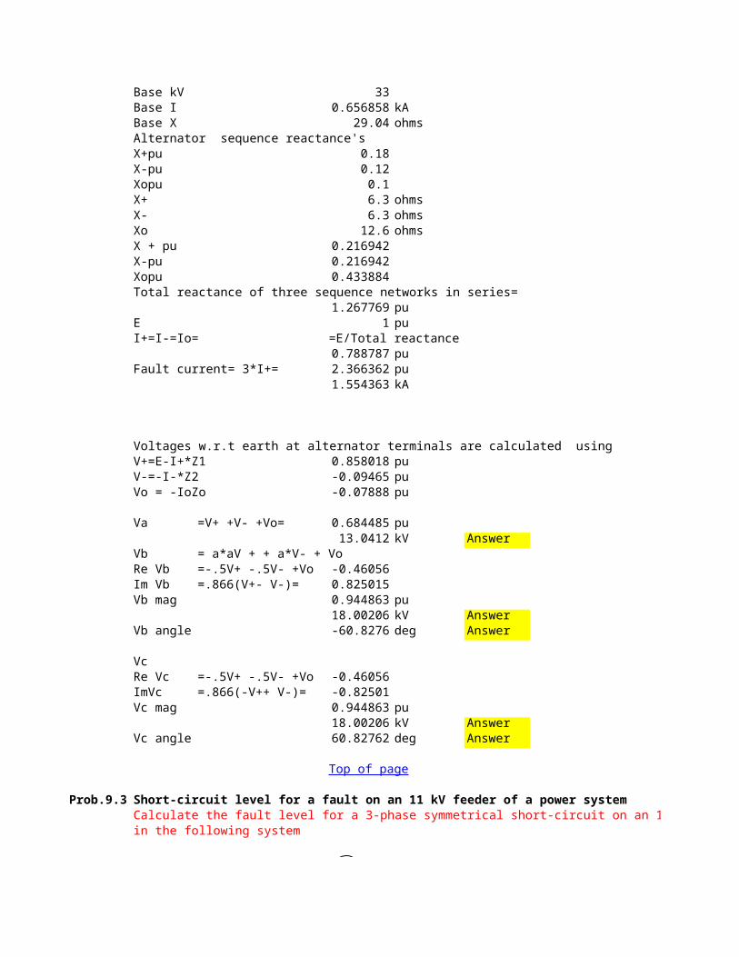
Base kV 33Base I 0.656858 kABase X 29.04 ohmsAlternator sequence reactance's X+pu 0.18X-pu 0.12Xopu 0.1X+ 6.3 ohmsX- 6.3 ohmsXo 12.6 ohmsX + pu 0.216942X-pu 0.216942Xopu 0.433884Total reactance of three sequence networks in series=
1.267769 puE 1 puI+=I-=Io= =E/Total reactance
0.788787 puFault current= 3*I+= 2.366362 pu
1.554363 kA
Voltages w.r.t earth at alternator terminals are calculated usingV+=E-I+*Z1 0.858018 puV-=-I-*Z2 -0.094654 puVo = -IoZo -0.078879 pu
Va =V+ +V- +Vo= 0.684485 pu13.0412 kV Answer
Vb = a*aV + + a*V- + VoRe Vb =-.5V+ -.5V- +Vo -0.460561Im Vb =.866(V+- V-)= 0.825015Vb mag 0.944863 pu
18.00206 kV AnswerVb angle -60.82762 deg Answer
VcRe Vc =-.5V+ -.5V- +Vo -0.460561ImVc =.866(-V++ V-)= -0.825015Vc mag 0.944863 pu
18.00206 kV AnswerVc angle 60.82762 deg Answer
Prob.9.3 Short-circuit level for a fault on an 11 kV feeder of a power systemCalculate the fault level for a 3-phase symmetrical short-circuit on an 11 kV feederin the following system
Top of page

Remainder of GridGrid infeed= 1500 MVA
132 kV
2 X 50 MVA,12.5 %4 X 25 MVA,16%
11kV 11kV
5.3 % on 25 MVAF
Generator reactance 0.16 puGenerator MVA 25Transformer reactance 0.125 puTransformer MVA 50Reactor reactance 0.053 puReactor MVA 25Grid infeed 1500 MvaBase MVA 100Grid infeed on base MVA 15 puE Grid voltage 1 puEI Grid voltamp 15 puGrid source reactance (pu)=E/I = E*E/E*I
0.066667 puGenerator reactance on common base
0.64 puTransformer reactanc on common base
0.25 puReactor reactance on common base
0.212 puSolution: pu equivalent circuit
1 pu emfj.0667
j.64 j.64 j.64 j.64
j.25 j.25
j.212IF
Reduce the circuit by combining two parallel branches and converting delta into star as
follows:

1 pu emf
a0.0667
b0.0878
0.32 0.32
e0.0743 0.0743
c d
IF
Further reduction gives
a
a0.32 0.1105
e .117 puc
0.0743c
IFIF
Fault MVA= 100/.117854.70085 MVA Answer
The circuit breaker will thus be rated at the next standard size 11kV,1000MVA
Prob.9.4 Fault current and the voltage at the healthy phase for a line-line fault at the remote end of a line connected to an alternatorA 3- phase 33 kV 37.5 MVA alternator is connected to a 33 kV overhead line which develops a short-circuit between phases b and c at the remote end . The positive and negative sequence reactances are 18 and 12 % (on rating) while those for the line are
6.3 ohms each. Calculate the fault current , and the voltage of the healthy phase to earthat the fault point.
Solution: Base MVA 37.5Base kV 33Base X 29.04 ohmsXg+ 0.18 puXg- 0.12 pu
Top of page

Xl+ 6 ohmsXl- 6 ohmsXl+ 0.206612 puXl- 0.206612 puX1 Total positive sequence reactance = Xg+ +Xl+
0.386612 puX2 Total negative sequence reactance = Xg- + Xl-
0.326612 puSequence network connections for a line to line fault
f1 f2Z1 Ia1 Z2 Ia2
EVa1 Va2
E 1 puIa1 =E/(X1+X2 -j 1.402086 puIa2 =-Ia1 j 1.402086 puIb =a*a* Ia1+a*Ia2=(a*a-a)Ia1, where a= -.5-j.866,(a*a-a)=-j1.732
Ib -2.428413 puIb mag 2.428 pu
1.59485 kA AnswerIb angle 180 deg
At the point of fault (healthy phase -a),Va1 0.457937 pu
angle 0 degVa2 =Va1 0.457937 pu
angle 0 degVae =Va1+Va2= 0.915874 pu
17.44976 kV Answerangle 0 deg
Fault MVA=1.59485*33= 52.63006 MVA
Prob.9.5 Generator supplying power to a synchronous motor via a transmission line- To find fault currents in the machines for a 3-phase fault at the alternator terminals
A 22 kV 100 MVA alternator with .25 pu transient reactance is supplying a load through a
transmission line of reactance .05 pu at 100 MVA. The load at a particular time is equivalent to a 50 MVA synchronous motor with .2 pu transient reactance which is taking 40 MWat .8 pf leading with a terminal voltage of 21.9 kV.If a 3-ophase short-circuit occurs at the alternator terminals, calculate the current in eachof the two machines and in the fault during The transient period.
Solution: MVAb base value 100
=E-Ia1jX1
Top of page

kVb base value 22Ib base value 2624.321 APm motor load 40 MWVm motor voltage 21.9 kV
0.995455 pupfm motor pf 0.8 leadIm motor current 1318.152 A
0.502283 puMotor MVA 50Xm on equipment base 0.2 puXm' on 100 MVA base 0.4 puXg' 0n 100 MVA 0.25 puXl line reactance 0.05 pu
0.05
0.25 0.4Vg Vm
Eg' G M Em'
Vm is the reference phasor
= Im *pfm 0.401826 pu=Im*Sin(acos(pfm) 0.30137 pu
Vg = Vm+jXl(Re Im +j Im Im)= Vm -Xl*ImIm 0.980386 pu
0.020091 pu
0.905044 pu= ImVg + 'Xg'''*Re Im 0.120548 pu
1.116002 pu=-Xm*Re Im -0.160731 pu
Total fault current during the transient period is found by superposition of Ig' and Im' whichflow through the switch.
Ig' =Eg'/jXg'Re Ig' 0.482192 pu
1265.426 AIm Ig' -3.620174 pu
-9500.498 AIm' =Em'/(jXm'+jXl)Re Im' -0.357179 pu
-937.3525 AIm Im' -2.480006 pu
-6508.33 ATotal current in each phase of the short-circuit:Real part= 328.0734 A Answer
Re ImIm Im
Re VgIm Vg =Xl *Re ImEg' = Vg+ jXg*(ReIm+jIm Im)Re Eg' =Re Vg-Xg*Im ImIm Eg'Em' = Vm-jXm'*(ReIm+jImIm)Re Em' =Vm+Xm*Im ImIm Em'

Im Part= -16008.83 A Answer
Prob.9.6 To find the reactance of the current limiting reactors to limit the fault currentThree star-connected 11 kV alternators are connected each in series with a similar current-limiting reactor to a common busbar. The alternators each have a rating of 10 MVA and subtransient reactance per phase of .06 pu. Two 11/33 kV transformers of 15 MVA rating,
.03 pu reactance , and 10 MVA, .02 pu reactance respectively, connected in parallel to this
busbar, supply a transmission line of impedance .2 + j .7 ohms /km. At a substation 10 km from the generating station is a 25 MVA 33/11 kV transformer of .06 pu reactance. Calculate the reactance of the current -limiting reactors if each alternator is not to carry more than 2.333 times the full-load current, when a symmetrical short-circuit occurs on the11 kV busbars in the substation.
Solution: Generators, Xg = .06 pu, 10 MVA
Reactors ,X
Transformers,10 MVA, Xt1=.02 pu 15 MVA, Xt2=.03 pu
Line Zpu = Rl+jXl = .2 +j .7 (ohms /km)
Transformer 25 MVA Xt3 =.06 pu
F
MVAb 25l Line length 10 kmRl' line resistance/km 0.2 ohms/kmXl' line reactance /km 0.7 ohms/kmRl =Rl'*l 2 ohmsXl =Xl'*l 7 ohmsVb in line 33 kVRlpu = Rl*MVAb/(Vb*Vb) 0.045914 puXlpu =Xl*MVAb/(Vb*Vb) 0.160698 puXg' on generator base 0.06 puXg on common base =.06*25*11*11/(10*33*33)
0.016667 puMVAt1 transformer t1 rating 10 MVA Xt1'= 0.02 puMVAt2 transformer t2 rating 15 MVA Xt2'= 0.03 puMVAt3 transformer t3rating 25 MVA Xt3'= 0.06 pu
Xt1 on common base 0.05 pu
Top of page

Xt2 on common base 0.05 puXt3 on common base 0.06 pupu Reactance diagram:
1 2 3 4 I 5
1=generator reactance of 3 generators in parallel= 0.005556 up2=reactance of 3 reactors in parallel=X/3, X is the unknown3= reactance of two transformers in parallel= 0.025 pu4= line Impedance= R 0.045914 pu
X 0.160698 pu5= transformer reactance = Xt3 0.06 pu
Total reactance 0.251253 +X/3
Total impedance= .0459+j(.251+X/3)
Fault current in the pu circuit=I=1/(.0459+j(.251+X/3))
Magnitude of fault current= Imag= 1/sqrt(.0459*.0459+(.251+X/3)*(.251+X/3))
Fault current in each alternator=Imag/3MVA rating of each alternator = 10 kV rating 11Full load current of each alternator = MVA rating/1.74* kV rating= 524.8641 AIb base current 437.3868 AFull load current of each alternator, pu
1.2 puTherefore this value times (7/3) should be equal to Imag/3 .or,
.0459*.0459 +(.251+X/3)*(.251+X/3)= (1/8.4)*(1/8.4)or,X= 0.42347 puX ohms 18.44637 ohms Answer
Prob.9.7 A generator supplying power to a motor: For the single phase fault at the generator terminals,to find the fault current( in the faulted phase ) flowing into thefault and the contributions of the generator & motor to the fault.In the following figure, G is an exporting grid area(generator0 having a 3-phase fault levelof 20000 MVA at the 400 kV busbars S. The corresponding data for the grid imporing rea M
(motor) is 10000MVA at R. The short 400 kV line has a series reactance of 40 ohms /phase.
The load transfer is 150 MW, .8 pf lagging, 360 kV at R. If ahort circuit to earth occurs on
Top of page

one phase at S, calculate the current (in phase A) flowing into the fault and the contributions of the generator & motor to the fault current (in phase A).
jXg S R jXmj40 ohms
GM
For both area during the subtransient period, the negative and zero sequence reactancesmay be assumed to be 100 % and 50 % respectively of the positive sequence values for the grid areas and 100% and 20% for the line. Both G and M are solidly earthed.
Solution: MVAg fault, MVA of gen. 20000 MVAV busbar Voltage 400 kVIg Gen fault current 28.90173 kAXg Source reactance 7.990531 ohm/phMVAm for motor 10000 MVAV for motor 400 kVIm for motor 14.45087 kAXm for motor 16 ohm/phTake VR as reference phasorVR L-L 360 kV
L-N 207.8462 kV/phP Load power 150 MWpf load pf 0.8 lagIm load current magnitud 0.30106 kA
0.240848 kA0.180636 kA
Xl line reactance 40 ohms
208.0268 kV/ph215.0716 kV/ph
= Re Im *Xl 9.633911 kV/phThis is the balanced pre-fault voltage at S……..= VfThe following are generator , line and motor sequence reactances:Xg+ 7.990531 ohmsXg- 7.990531 ohmsXg0 3.995266 ohmsXl+ 40 ohmsXl- 40 ohmsXl0 8 ohmsXm+ 16 ohmsXm- 16 ohmsXm0 8 ohmsThe following shows thew sequence network for a single -line to ground fault.
Re ImIm Im
VS = Vr + ImIm * jXlRe VSIm VS

Xg+ Vf= VSXg-Xg0Xl+Xl- Xg+ Xl+ Xg- Xl- Xg0 Xl0
Xm+ Xm- Xm0
Z1 Z2 Z0
=(Xg0*(Xl0+Xm0)/(Xg0+Xl0+Xm0)=(Xg-*(Xl-+Xm-)/(Xg-+Xl-+Xm-)
=(Xg+*(Xl++Xm+))/(Xg++Xl++Xm+)
Z1 6.99275 ohmsZ2 6.99275 ohmsZ0 3.196969 ohmsFault current flowing from A phase conductors into the fault at S isIae =3*Vf/(Z1+Z2+Z0)Re Iae =3*ImVf/(Z1+Z2+Z0) 1.682048 kAIm Iae =3*Re Vb/(Z1+Z2+'Z0')
37.55077 kAReal part of Positive sequence current in phase A fed into the fault from the generator is
0.49067 kAImaginary part of Positive sequence current in phase A fed into the fault from the generator is
10.95393 kAand real part of positive sequence current from motor is
0.070013 kAand imaginary part of positive sequence current from motor is
1.562995 kANegative sequence currents are the same.
Real part of Zero sequence currents in A phase fed into fault from G is 0.448652 kA
Real part of Zero sequence currents in A phase fed into fault from G is 10.01591 kA
and from motor is :Real part 0.11203 kA

Imag.part 2.501014 kATo these fault currents must be added the load current which is wholly positive sequence,in order to give the actual current in any part of the system.The positive sequence current in phase A flowing from G is =0.49067- j10.953+(0.24-j.18)=0.712-j10.74 kAfrom M is .07-j1.56 -(.24-j.18)=-.173-j1.33 kAActual current in phase A flowing from G is =.712-j10.74+.472-j10.56+.517-j11.57=1.7-j32.87 kAand from motor is=-0.173-j1.33+0.067-j1.51+0.023 -j.527=-0.083-j3.367 kAor .083 +j 3.367 to motorSum of these actual currents in phA is =1.701-j32.87 -.083-j3.37=1.618 -j 36.24 kA that is the actual fault current.
Prob.9.8 Line-to-line fault at the terminals of agenerator-To find fault currentThe positive ,negative, and zero sequence reactances of a 15 MVA,11kV synchronous generator are .3pu,.2pu, and.1pu respectively.The generator is solidly earthed and isunloaded. A line-to-line fault occurs at the terminals of the generator.Determine the faultcurrent.
Solution: The sequence network is shown below:
Ea
Va1 Va2
Z1= j 0.3 pu Z2=j 0.2 pu
Ia1 Ia2
Assume that phases b and c are faulted.Let Ea= 1 0 deg.puFor the line-line fault,Ia=0
Ia1=-Ia2 = 1 0 deg.Z1+Z2
Z1= .3iZ2= .2i
Ia1=-Ia2 = -2iThe fault current is Ib= Ib0+Ib1+Ib2=0+a*a.Ia1+aIa2a= -0.5+0.866i
Top of page

a*a= -0.5-0.866iIb= -3.464 pu
Base MVA= 15BasekV(L-L)= 11Base current= 787.2962 A
Fault current= -2727.194 A Answer
Prob.9.9 To find fault curent & voltages for a DLG fault at the terminals of an unloaded generatorA double line to earth fault occurs at the unloaded generator terminals in Prob.8.8.Calculate the fault current and the line voltages
Ea
Va1 Va2 Va0
Z1= j 0.3 pu Z2=j 0.2 Z0=j 0.1
Ia1 Ia2 Ia0
Assume that phases b and c are faulted to earth.Let Ea= 1 0 deg.pu
Ea1= 1Z1= .3iZ2= .2iZ0= .1i
Ia1= Ea/(Z1+(Z0Z2/(Z1+Z2)))
= -2.72727272727272i pu
Va1= Ea-Ia1Z10.181818181818184 pu
Va2=Va1 0.181818181818184 puVa0=Va1 0.181818181818184 puIa2=Va2/Z2 -0.90909090909092i puIa0=Va0/Z0 -1.81818181818184i puThe fault current to earth is Ib+Ic.Ib+Ic= (Ia0+a*aIa1+a.Ia0)+(Ia0+a.Ia1+a*a.Ia2)
= 2*Ia0+(a+a*a)(Ia1+Ia2)
Top of page

= 2Ia0-(Ia1+Ia2)Since Ia=0, we may write Ia=Ia0+Ia1+Ia2=0or,-(Ia1+Ia2)=Ia0.Therefore , fault current = Ib+Ic=3 Ia0=
-5.45454545454552i puSince Base current in Prob.9.8= 787.3 AFault current= -4294.36363636369i A AnswerThe line voltages are calculated as follows:Va=3Va1= 0.545455 puVb=Vc= 0Vab=Va= 3.464103 kV AnswerVbc= 0 AnswerVca=Va= 3.464103 kV Answer
Top of page

=(Xg0*(Xl0+Xm0)/(Xg0+Xl0+Xm0)