Embed Size (px)
Citation preview

Chapter 8 – Naiad repair One of the primary reasons for lifting the boat in September of 2016 was to do a full evaluation and service of our Naiad hydraulic stabilizer system.
Figure 1: Naiad port side fin circled in red
We have been concerned about the system since we pulled the boat in September of 2014 to get the Naiad lower seals replaced. When the seals were removed, liquid oily substance drained out. I don’t believe it contained any water but that has always been the concern. Advice from “experts” has ranged from “don’t even thing about reassembling the system until it is completely disassembled and you may even have to replace the shafts at $1000 each” to “its likely oil from the leaking cylinders at the top of the assembly leaking through the top seal” to “its common that over time the grease separates and thin oily liquid will drain”. Everyone has agreed that as long as grease and/or water is not pushing up though the top seal into the boat (see photo below from Duet the 50) that this is not an emergent situation. None-the-less we would like to get this figured out and taken care of once and for all.

Figure 2: (NOT Salish Aire) - but an example of grease being forced out of the actuator into the boat as a classic warning sign of water intrusion below
We looked for a boat yard that had a mechanic that was 1) familiar with the Naiads, and 2) willing to let me do whatever work I can both to save money and to learn about how to repair them myself in the future.

Figure 3: Haven Boatworks in Port Townsend Washington had a mechanic familiar with Naiads who was willing to act as my mentor
Prior to even getting to the boat yard I contacted Naiad with a list of parts that I think should pretty much repair / replace anything that is likely to have aged or failed. Initially I was told by Naiad that they normally don’t sell this level of parts to a boat owner but after our yard folks called and spoke to them they agreed to sell to me directly. The parts came to about $3000 (see the breakdown at the end). So far I have installed an aftermarket pressure gauge to replace the non-functioning gyro gauge. I have removed and taken apart the oil reservoir and replaced the thermometer on the front of the reservoir as well as the overtemp and underfill electrical switch assembly from inside of the unit. Takedown, cleaning, reassembly, and lifting it back into the difficult to reach corner where it is mounted to the better part of 2 days.

Figure 4: Naiad reservoir with new thermometer / level sight gauge installed

Figure 5: sender unit with oil level and over temp sensors that goes in the center of the reservoir
I had previously replaced the seals in the leaking hydraulic pump and replace the high and low pressure hoses from the pump to the reservoir. I was able to source the replacement parts kit from the internet as this is a common industrial pump. A local bearing supply dealer had a replacement rubber insert for the drive coupling.
Figure 6: Vickers hydraulic pump driven directly off the front pulley of the Lugger
Getting to the top of the fin assemblies inside of the boat takes some minor disassembly of the bed in the guest stateroom and the vanity in the aft head. Once the panels/furniture are removed it is pretty easy to reach the parts. The first thing I wanted to do was to replace the seals in the hydraulic cylinders as I was quite sure that the shaft seals were the source of the oil on top of the assemblies. I figured if I was removing and disassembling the cylinders anyway then I might as will install full seal kits. Naiad charged me about $70 per kit (X2) for kits that contained 4 seals each. When I looked carefully I realized only one of the seals fit my cylinders – luckily it was the lip seals that I suspect were leaking. Just to be sure I had the correct parts I called Naiad customer service. To summarize: I have gray colored cylinders made by Van Dusen and Meyer company who is long out of business. Naiad cannot get the correct seal kits any longer and it was just luck that the one seal I needed was included in the kit. The Naiad rep and I talked about replacing the cylinders for about $800 each or if it was reasonable to try the lip seal and then pressure test the cylinders to see what happens. I put everything back together with the new lip seals and then devised a bench test rig using Clarice’s father’s hydraulic hand pump. There was no sign of leakage with the testing and so I do plan to reinstall the original cylinders. Finally, since the kits came with a Parker number on them (RK2AHL0061) I sourced a second set on the internet for $9 each and ordered an extra set to have on hand. Clearly cost control on a job like this is a challenge.

Figure 7: Fully assembled upper end port side.

Figure 8: Partially disassembled Stbd side unit - access is a bit more of a challenge as it is under the vanity in the aft head
The fins were removed with the manual screw-in tool purchased from Naiad. This is a screw with a socket fitting at one end but I was told by a Naiad company technician at a boat show to not even think about trying to make one as they are specially hardened and if the threads should strip on a home built model the repair costs can be a couple thousand dollars. The first step of the fin removal process is to remove the bolt that holds them on. This takes a 1 3/8 socket, a long extension, and a breaker bar plus a pipe capable of breaking loose a bolt that is initially tightened to 300 ft lbs . Once the bolt is removed the removal tool is threaded into threads in the fin and then tightened until the fin pops loose from its taper fit shaft by pushing on the end of the shaft. In preparation for the sudden drop of the fin blocks are put under it leaving a small bit of free space above the top block. We tightened the tool with a ¾ drive breaker bar plus about 2 ½ feet of iron pipe for a leverage extension. The good news is that the tool works much better than we expected and we had both fins down in a short time. (The guy from Haven commented that it was also much tidier than using the hydraulic tool).

Figure 9: Tools used to remove fins including 3/4 drive breaker bar and extension pipe, 1 3/8 socket, 12 in extension, and Naiad removal tool (circled)
I had watched carefully when the outer seals were replaced in 2014 and so getting them out was pretty straight forward. They are held in place with a cover which is held in with 4 Allen screws. To get the seals out (they are a stacked set of 2) the recommended plan is to drive a long sheet metal screw into both sides of the seal and it will walk itself out. Next is the bearing cover which is held in by several more Allen screws. Since the cover tight fits into a lip in the main casting of the fin assembly it would be really difficult to get out if it weren’t for two 3/8 -16 drive screw holes provided by Naiad engineers. The holes are filled with Allen set screws which are removed and then bolts (I used grade 8 to avoid any chance of stripping the threads) are driven into the holes which pushes the cover out. My only concern so far is in finding that the bottom of the main casting has rusted and chipped away a bit. Since the pressure seal is really in the lip there is not a concern it will leak but I am still trying to think of a way to keep it from deteriorating more.

Figure 10: removal of seal cover (inner ring - outer ring is the bearing cover)

Figure 11: Showing removal of seals using screws (2 stacked seals both with lips down). Also showing location of one of the jack screw holes used to force the bearing cover off.
Next I moved from outside of the boat to inside at the top of the fin assembly. I removed the main shaft which is held in by a single loose bolt (it is used for height adjustment) and a clamping assembly that keys onto the top of the shaft and provides the lever arm for the hydraulic cylinder (previously removed) to turn. It is interesting that this is really all that keeps the fins from dropping out of the boat – but clearly it works reliably. The lever arm is held onto the top of the bearing shaft assembly by three bolts and then it lifts off easily. The bearing is held in by a plate the sits firmly inside of the top seal. Again Naiad engineers provided a 3/8 – 16 threaded hole for a jack screw which lifted the cover easily off. Next I used a huge screwdriver as a pry bar to lift out the top seal (this sounds easy but took a bit of banging and levering to accomplish). Now the bearings and bearing shaft are easily in view. When the seals were changed in 2014 I was told that the assembly needed to be taken to a shop for the bearings to be pressed on and the grease loaded. Now that I see how it is assembled – unless the whole casting were removed this is a bunch of hogwash (I won’t name a company I am not pleased with for general consumption on the internet but this supports my plan to never use that company again). Bottom line is that the bearing shaft must be tapped out of the bearing in order for it to be removed from the boat. I found that tapping it firmly with a brass hammer forced it out of the upper bearing and the shaft and lower bearing dropped out of the bottom of the boat into my wife’s waiting hands. The lower bearing comes off the top of the shaft and thus must be pressed off its home seat and then the upper bearing seat as well. Haven had a press that made easy work of this step. The final disassembly steps involved using a bar to on the inner edge of the 2 bearing races and tapping on the bar to force the races out, one
under the boat and one into the boat. Now it was just a matter of wiping out about a pint of white grease so that the reassembly process can begin.
Figure 12: Main shaft that comes out first; bearing shaft with the lower bearing still in place and one of the 2 bearing races. (There is a lip on the bearing shaft that is not visible in this photo that makes it impossible to remove the lower bearing without taking it up the full length of the shaft and off of the top end).
To install the lower bearings on the bearing shafts we heated them with a torch and they dropped right on. I tried using a similar trick to get the races to drop in place by putting them in the boat’s freezer but it wasn’t enough so they ended up being tapped into place with a hammer and bar. Next the lower bearing was loaded with grease and lifted into the waiting race from under the boat while the bearing cover (already set up with sealant on the sealing surfaces) was put over it (this took 2 people to accomplish) and a couple of bolts started to hold everything in place. The bolts (Allen socket head style) were then treated with Lock Tight and torqued to 15 ft lbs as called out on the Naiad drawings. From the top side I loaded the cavities with 30 oz of Lubriplate Marine lubricant per side. Again I tried heating the bearings to 400 degrees F in the oven hoping they would drop onto the shafts but was only partially successful as the grease and metal quickly cooled and shrunk them on contact. To press them the rest of the way I temporarily installed the cover and torque arm and then used the 3 bolts that normally hold them to pull the shaft and bearing into final alignment. Next I removed the cover and

torque arm so that I could tap the top seal into place and then I reassembled everything and did a final torque of the torque arm bolts to 60 ft lbs as called out on the Naiad drawings. Back to the bottom of the boat to install the main shafts. One person pushed them into place up through the splines of the torque arms. I held them in place with the top bolt and washers but purposefully did not fully raise them into position. The two seals were installed next from the bottom after the outer edges were coated with sealant. Finally the seal covers were installed to hold the seals in after putting Lock Tight on the four socket head screws and sealant on the inside of the cover (I’m not sure if this is necessary but it was done by the last installer so I followed his lead). Now the top bolts were tightened while a second person watched from below. Since my shafts have some scratches at the bottom of where the seals previously hit, I wanted the new seals to at least partially ride on a new section of the shafts. Naiad’s instructions indicate that with a fast boat the fins need to ride pretty close to the hull but since we are not a fast boat I understand that lowering the fins is not an issue. Once the shaft height was adjusted then the spline lock bolts were tightened to 90 ft lbs as called out on the Naiad drawings. And the shafts were ready to use.
We had 3 people to lift the fins onto the locked shafts. 2 to lift and 1 to start the bolt in place. The fins can swivel freely on the shafts (they are not keyed to the shafts) until the taper is pulled up tight. Naiad is pretty clear that the taper should be very clean without any oil or scratches on it. Salish Aire seems to be happy with her fins parallel to the hull in the locked position. Once the fin was on the shaft and the bolt started (we did put Never Seize on our bolt – Naiad calls out torques for with and without Never Seize) one person can hold it parallel while the other snugs the bolt with its 4 cupped washers with the cups up. Next the bolts are torqued to 300 ft lb in our case and they are ready to go.
Our final steps were to replace the actuator cylinders, finish the top end assembly and fill and test the system.
Outcome: We have had the system running for a few hours as of this writing. Everything seems to be working correctly. We do have some minor oil leaking from the port actuator – this was not totally unexpected as I expect that the shaft lip seal will need a bit of break-in time (fingers crossed).
Summary: I do NOT claim to be a professional mechanic but found that replacing bearings and seals in my Model 201 Naiad stabilizers was a very doable project with my skill set. This document is NOT intended to be a full instruction set but rather simply a description of my experience with this project.
I believe I could have saved more money by sourcing my parts other than through Naiad but felt more confident that I would get what I needed if I went directly through them. I again emphasize that while I found the manual fin removal tool to work very well and fond it to be very expensive, I would NOT try to make one myself as it is clearly been subjected to a very specific hardening process.
I did find that Naiad is great about answering their phone and quickly getting a knowledgeable technician to talk to on the other end.
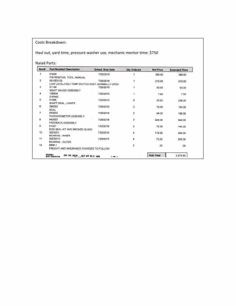
Costs Breakdown:
Haul out, yard time, pressure washer use, mechanic mentor time: $750 Naiad Parts: