Embed Size (px)
Citation preview

Chapter 8
Erosion Control Practices


Nelson/Tasman Erosion and Sediment Control Guidelines – June 2019 Chapter 8 – TOC Page i/ii
TABLE OF CONTENTS
8 EROSION CONTROL PRACTICES ................................................................................................... 1
8.1 Introduction ............................................................................................................................. 1
8.2 Water Management Controls ................................................................................................. 1 8.2.1 Check dams ............................................................................................................... 2 8.2.2 Temporary Contour Drains (Cut-Offs) ....................................................................... 5 8.2.3 Diversion Channels ................................................................................................... 8 8.2.4 Pipe Drop Structures and Flumes ........................................................................... 14 8.2.5 Surface Roughening ................................................................................................ 17 8.2.6 Benched Slopes ...................................................................................................... 19 8.2.7 Stabilised Entranceways ......................................................................................... 22
8.3 Soil Stabilisation Practices .................................................................................................. 25 8.3.1 Topsoiling and Grass Seeding ................................................................................ 26 8.3.2 Hydroseeding........................................................................................................... 31 8.3.3 Mulching .................................................................................................................. 33 8.3.4 Turfing ...................................................................................................................... 36 8.3.5 Geotextiles and erosion control blankets ................................................................ 38 8.3.6 Dust control.............................................................................................................. 42
LIST OF TABLES
Table 8-1 Erosion Controls........................................................................................................................ 1 Table 8-2 Positioning of check dams ........................................................................................................ 3 Table 8-3 Contour Drain Spacing .............................................................................................................. 7 Table 8-4 Mannings roughness coefficient for a range of materials ....................................................... 10 Table 8-5 Sizing criteria for pipe drop structure ...................................................................................... 15 Table 8-6 Sizing criteria for flumes .......................................................................................................... 16 Table 8-7 Benched slope spacings ......................................................................................................... 20 Table 8-8 Stabilised entranceway specifications .................................................................................... 23 Table 8-9 Typical seed and fertiliser application rates ............................................................................ 29
LIST OF FIGURES
Figure 8-1 Check dams installed in series to act as a water velocity control measure .............................. 2 Figure 8-2 Fabric filled check dams in conjunction with erosion control matting. Note flow evidence over
the centre portion of the dams .................................................................................................. 3 Figure 8-3 Rock check dams (Figure: Auckland Council) .......................................................................... 4 Figure 8-4 Contour drains illustration (Figure: BOPRC) ............................................................................. 5 Figure 8-5 Contour drains established on embankments as a water control measure in conjunction with
progressive stabilisation. ........................................................................................................... 6 Figure 8-6 Contour drain intercepting slope runoff. Note straw mulch to reduce raindrop impact ............. 6 Figure 8-7 Contour Drain Detail (Note the heights are indicative only) ...................................................... 7 Figure 8-8 Diversions for intercepting clean water (left) and dirty runoff (Photos courtesy of BOPRC and
Ridley Dunphy Environmental Limited) ..................................................................................... 8 Figure 8-9 Area and hydraulic radius calculations for parabolic and trapezoidal profiles ........................ 11

Nelson/Tasman Erosion and Sediment Control Guidelines – Draft for Discussion June 2019 Chapter 8 - TOC - Page ii/ii
Figure 8-10 Cross section of clean water diversion ................................................................................... 11 Figure 8-11 Cross section of dirty water diversion ..................................................................................... 12 Figure 8-12 Pipe drop structure (note check dams, silt fence and channel protection also) ..................... 14 Figure 8-13 Flume to a sediment retention pond ....................................................................................... 14 Figure 8-14 Wooden flume lined with impervious material ........................................................................ 15 Figure 8-15 Flume and pipe drop structure design. (Figure: Auckland Councils’) ..................................... 16 Figure 8-16 Surface roughening with a bulldozer....................................................................................... 17 Figure 8-17 Slope roughening in conjunction with stabilisation ................................................................. 18 Figure 8-18 Slope roughening in conjunction with stabilisation .................. Error! Bookmark not defined.
Figure 8-19 Benched Slope ........................................................................................................................ 20 Figure 8-20 Benched Slope with Reverse Benches ................................................................................... 20 Figure 8-21 Stabilised Entranceways ......................................................................................................... 22 Figure 8-22 Example of a shaker ramp in site access point ...................................................................... 23 Figure 8-23 Stabilised construction entrance showing progression of construction with filter fabric
underlay prior to stone placement........................................................................................... 24
Figure 8-24 Stabilised construction entrance
Figure 8-25 Vegetative stabilisation is an effective erosion control practice .............................................. 26 Figure 8-26 Grass strike densities - percent coverage .............................................................................. 27 Figure 8-27 Hydroseed being applied to a vertical face and the eventual stabilisation (photos courtesy of
Erosion Control Ltd). ............................................................................................................... 31 Figure 8-28 Recently applied hydroseed showing emergent grass growth ............................................... 32 Figure 8-29 Application of straw mulch as a temporary ground cover ....................................................... 33 Figure 8-30 Recently applied mulch (Photo courtesy of BOPRC) ............................................................. 33 Figure 8-31 Straw mulch being crimped into ground to reduce windblown potential ................................. 35 Figure 8-32 Well applied mulch and vegetative cover (photo courtesy of BOPRC and Ridley Dunphy
Environmental Ltd) .................................................................................................................. 35 Figure 8-33 Turf being applied to provide immediate ground cover .......................................................... 36 Figure 8-34 Turf being applied for a swale outfall ...................................................................................... 36 Figure 8-35 Erosion control blanket for slope protection. Notice grass growing through blanket .............. 38 Figure 8-36 Plastic cover to prevent slope erosion .................................................................................... 39 Figure 8-37 Plastic cover providing slope protection with plantings placed throughout the cover. ............ 40 Figure 8-38 Geotextile Design on slopes (figure courtesy of Auckland Councils’) .................................... 40 Figure 8-39 Geotextile Design on outfalls (figure courtesy of Auckland Councils’) ................................... 41 Figure 8-40 Dust suppression by water sprinkling ..................................................................................... 42

Nelson/Tasman Erosion and Sediment Control Guidelines – June 2019 Chapter 8 - Page 1 of 44
8 EROSION CONTROL PRACTICES
8.1 Introduction
This section considers erosion control from two aspects:
1. Water Management: controlling the volume and rate of water runoff from within and around the land
disturbance area; and
2. Stabilisation: Providing a protective cover against sediment generation and transportation
In any land disturbance site, both of these types of practices will most likely be required. However, the
choice of which erosion control measure is to be used will depend on the specific site constraints and the
project construction sequencing.
The erosion controls outlined in this section are summarised in the table below:
Table 8-1 Erosion Controls
Page Ref
Water Management Controls
Check Dams
Contour drains (Cut-offs)
Diversion channels and bunds
Pipe Drop Structures and Flumes
Surface Roughening
Benched Slopes
2
5
8
14
17
19
Stabilisation Methods
Stabilised Entranceways
Topsoiling and grass seeding
Hydroseeding
Mulching
Turfing
Geotextiles, plastic covers and erosion control blankets
Dust Control
22
26
31
33
36
38
42
8.2 Water Management Controls
Control of site runoff is one of the most important erosion control measures that can be done in your works
area. These practices help to reduce water velocities, which in turn reduce erosion, and provide some
reduction in contributing catchments requiring treatment with the overall aim of minimising sediment
generation. The key philosophy is keeping offsite (clean) water clean and away from disturbed areas,
keeping velocities low and diverting sediment laden (dirty) water to sediment retention devices.
Check dams, contour drains, diversion channel/bunds, pipe drop structures, surface roughening and
benched slopes are all examples of common measures to control water and runoff on land disturbance
sites. These practices are discussed in subsections 8.21 to 8.26.
Nelson/Tasman Erosion and Sediment Control Guidelines – June 2019 Chapter 8 - Page 2 of 43
8.2.1 Check dams
Definition and purpose
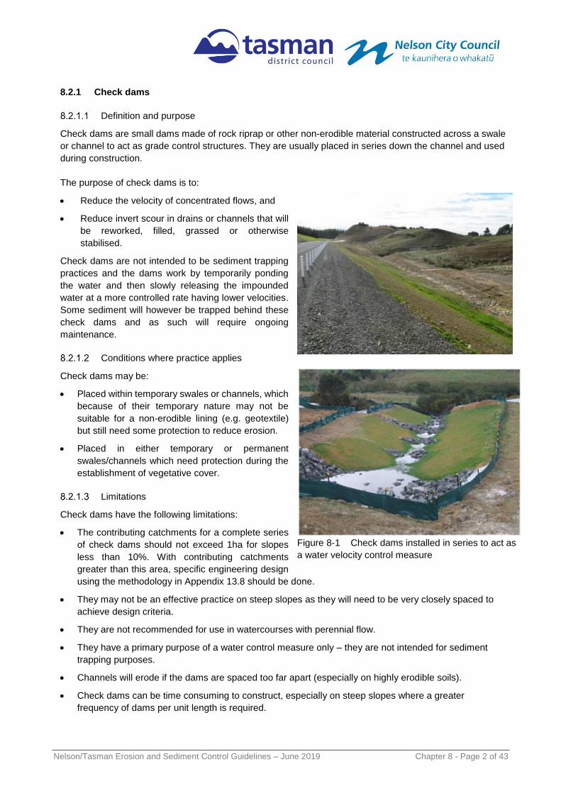
Check dams are small dams made of rock riprap or other non-erodible material constructed across a swale
or channel to act as grade control structures. They are usually placed in series down the channel and used
during construction.
The purpose of check dams is to:
Reduce the velocity of concentrated flows, and
Reduce invert scour in drains or channels that will
be reworked, filled, grassed or otherwise
stabilised.
Check dams are not intended to be sediment trapping
practices and the dams work by temporarily ponding
the water and then slowly releasing the impounded
water at a more controlled rate having lower velocities.
Some sediment will however be trapped behind these
check dams and as such will require ongoing
maintenance.
Conditions where practice applies
Check dams may be:
Placed within temporary swales or channels, which
because of their temporary nature may not be
suitable for a non-erodible lining (e.g. geotextile)
but still need some protection to reduce erosion.
Placed in either temporary or permanent
swales/channels which need protection during the
establishment of vegetative cover.
Limitations
Check dams have the following limitations:
The contributing catchments for a complete series
of check dams should not exceed 1ha for slopes
less than 10%. With contributing catchments
greater than this area, specific engineering design
using the methodology in Appendix 13.8 should be done.
They may not be an effective practice on steep slopes as they will need to be very closely spaced to
achieve design criteria.
They are not recommended for use in watercourses with perennial flow.
They have a primary purpose of a water control measure only – they are not intended for sediment
trapping purposes.
Channels will erode if the dams are spaced too far apart (especially on highly erodible soils).
Check dams can be time consuming to construct, especially on steep slopes where a greater
frequency of dams per unit length is required.
Figure 8-1 Check dams installed in series to act as
a water velocity control measure

Nelson/Tasman Erosion and Sediment Control Guidelines – June 2019 Chapter 8 - Page 3 of 43
They may not be a suitable option to provide erosion protection when highly erodible soils are
prevalent.
Key design criteria
Temporary check dams are typically constructed of
loose rock (riprap) or sandbags. Prefabricated and
re-useable triangular plastic material is also
available, and reinforced fabric dams can also be
used. However, it is critical that they are constructed
of competent material and do not erode themselves.
The check dams can either be constructed with a
450mm centre height or a 600mm centre height and
the following table is to be used to determine the
spacing of check dams for channel slopes within
indicated ranges.
Spacing for check dams are outlined in Table 8-2.
Table 8-2 Positioning of check dams
Slope of site (%) Spacing (m) between dams with a
450mm centre height
Spacing (m) between dams with a
600mm centre height
Less than 2% 24 30
2 – 4% 12 15
4 – 7% 8 11
7 – 10% 5 6
>10% Unsuitable – use stabilised channel
or specific engineered design Unsuitable – use stabilised channel
or specific engineered design
The maximum height of a check dam depends on the depth of the drain into which it is being placed.
As a general rule the centre height (spillway level) should be no higher than 600mm.
Incorporate a spillway into the design of check dams to direct flows over the centre of the structure with
the spillway elevation at least 150mm to 200mm lower than the crest of the structure.
To be effective, place check dams so that the toe of the upstream dam is at the same elevation as the
crest of the downstream dam. The standard detail of check dams is shown in Figure 8-1.
When used on highly erodible soils, check dams should be placed on a needle-punched geotextile
fabric to minimise the chance of water undermining the structure.
Figure 8-2 Fabric filled check dams in
conjunction with erosion control matting. Note flow
evidence over the centre portion of the dams

Nelson/Tasman Erosion and Sediment Control Guidelines – June 2019 Chapter 8 - Page 4 of 43
Figure 8-3 Rock check dams (Figure: Auckland Council)
Maintenance
Key items to check as part of the regular inspection includes:
Repair or reinstate the check dams if destroyed by machinery movement.
Inspect the check dams after rainfall or storms and repair as necessary.
Check if water is outflanking the structure and look for scouring around the edges of the check dam:
if so – increase the spillway depth, crest height and/or turn up edges of structure.
If scour is occurring between check dams, then additional structures may need to be provided.
Check dams should be inspected for sediment accumulation after each significant rain event.
Sediment should be removed when it reaches 40% of the original height or before this occurs.
Dispose of removed sediment to a secure area to ensure that it does not discharge to the receiving
environment.
Decommissioning
In decommissioning check dams consider the following:

Nelson/Tasman Erosion and Sediment Control Guidelines – June 2019 Chapter 8 - Page 5 of 43
Remove check dams when no longer needed, and where possible salvage all materials for re-use in
future check dams or other works.
Do not remove check dams that are protecting grass-lined channels until a complete and sustainable
cover has been achieved.
Fertilise and protect disturbed areas with surface mulch or erosion control matting if required.
8.2.2 Temporary Contour Drains (Cut-Offs)
Definition and purpose
Contour drains are temporary excavated channels or ridges or a combination of both, which are
constructed slightly off the slope contour.
The purpose of a contour drain is to:
Break overland flow draining down disturbed slopes by reducing slope length and thus the erosive
power of runoff.
To divert sediment laden water to appropriate controls via stable outlets. Note that they do not form
the same function as a Dirty Water Diversion Bund as they are more of a temporary feature.
Use as mid-slope contour banks and/or drains over the short-term. Temporary contour drain structures
should be placed across unprotected slopes within the working area at the end of each day’s work, before
site closedown or when rain is imminent.
Conditions where practice applies
The practice of using contour drains should be promoted on all earthwork’s sites, especially where there
are large areas of exposed ground and long steep slopes. The specific scenarios for their application
include the following:
To segment slopes so that the water flows on these slopes are reduced, limiting the erosion potential
of the water. They should be used at mid to lower slopes on all exposed areas.
Figure 8-4 Contour drains illustration (Figure: BOPRC)

Nelson/Tasman Erosion and Sediment Control Guidelines – June 2019 Chapter 8 - Page 6 of 43
To assist with the diversion of dirty water flows towards sediment retention devices (e.g. sediment
retention pond, decanting earth bund). Note that they do not form the same function as a Dirty Water
Diversion Bund as they are more of a temporary feature.
To use as cut-offs on tracking activities to direct water into a stable water table and/or outfall
structure.
Limitations
Contour drains have the following limitations:
Contour drains will concentrate sheet flows, thereby can increase erosion potential. This is of most
concern on any steep slope and in any vulnerable soils such as uncompacted fills and weak soils.
They may not be an effective practice on very steep slopes (>30%) as they will need to be very
closely spaced to achieve performance characteristics.
Unless the right sizing and spacing of drains is utilised, they have the potential to overtop during high
intensity rainfall events.
Steep contour drains longitudinal grades (> 2%) will increase flow velocities and may promote
erosion. In these circumstances’ drains will need to be lined to prevent scouring within the channel
invert.
Excessively flat contour drains grades mean sediment deposition is likely to occur, reducing capacity
and potentially resulting in overtopping of the structure.
Due to their temporary nature, they may be a “weak link”
in the overall treatment train by being installed too late or
not sized/spaced appropriately.
Key design criteria
Formal design of the contour drains is generally not
required due to their temporary nature. Although
commonly called contour drains, this term is misleading
as they need to be constructed slightly off the contour
(max grade 2%) to ensure they drain appropriately.
The following design principles are critical to their
effectiveness as an erosion control practice:
Minimum compacted bank height of 250mm.
Minimum depth of 500mm.
Longitudinal gradients not to exceed 2%
(otherwise lining may be required).
Be broad enough to create a low-profile bank so
that large earth working machinery can safely
cross. If this is not achievable, a dedicated
crossing using a temporary culvert can be used.
Avoid construction with a “V” profile instead use a
trapezoidal shape.
Outlets need to be carefully positioned to minimise
erosion and may need to be lined with geotextile
or other suitable material
Figure 8-5 Contour drains established on
embankments as a water control measure in
conjunction with progressive stabilisation.
Figure 8-6 Contour drain intercepting slope
runoff. Note straw mulch to reduce raindrop
impact

Nelson/Tasman Erosion and Sediment Control Guidelines – June 2019 Chapter 8 - Page 7 of 43
Indicative maximum catchment slope lengths are provided in Table 8-3 below.
Table 8-3 Contour Drain Spacing
Slope of site (%) Spacing (m) of contour drains
Less than 5% 50
5 – 10% 40
10 – 15% 30
15 - 30% 20
Specifications for contour drains are outlined in Figure 8-7.
Figure 8-7 Contour Drain Detail (Note the heights are indicative only)
Maintenance
Key items to check as part of the regular inspection includes:
Repair or reinstate contour drains if destroyed by machinery movement.
Inspect contour drains after rainfall or storms and repair as necessary.
Check the outfall for erosion and repair if required. It may be necessary to install a temporary flume
or provide geotextile.
Use sandbags during rainfall events if extra height is needed on the ridges of contour drains.
Decommissioning
Contour drains are typically removed after the rainfall event as part of the general earthworks’ activity.

Nelson/Tasman Erosion and Sediment Control Guidelines – June 2019 Chapter 8 - Page 8 of 43
8.2.3 Diversion Channels
Definition and purpose
Diversion channels are channels and/or bunds used
to convey either clean water to stable outlets or dirty
runoff to sediment retention devices. They are
constructed for a specific design storm.
For dirty water runoff, diversions are used to collect
and convey sediment-laden water within the
disturbed area, or inside the perimeter, to an
appropriate sediment retention device for treatment.
For clean water runoff, diversions are used to
intercept and divert offsite (clean) water away from
the works area. This minimises erosion by reducing
the volume of water flowing over the site and reduces
the amount of water than requires treatment, allowing
for more effective sediment control devices.
Clean Water Diversion Channels may be installed as permanent drainage works, but as a minimum are
installed throughout the duration of the earthworks programme. Permanent measures will require channel
invert and bank stabilisation to be installed.
Diversion of clean water is typically diversion of overland flow from either upper catchments or from
undisturbed areas on site. In some cases diversion of ephemeral streams may be required which needs
additional consideration of environmental effects and compliance with rules within the TRMP and NRMP for
works in watercourses - refer Chapter 10 for further detail. Diversion of intermittent or perennial streams is
also covered separately in Chapter 10. Diversion of watercourses may require resource consent.
Conditions where practice applies
Diversion channels are predominately used in the following situations:
To divert clean runoff water above the works site and divert to stable outlet(s).
As a physical “perimeter boundary” of an earthworks activity site to isolate the site and prevent
sediment from leaving the area.
To divert sediment-laden water to an appropriate sediment retention device (e.g. sediment retention
pond or decanting earth bund).
Limitations
Clean water and dirty water diversions have the following limitations:
They should not be confused with temporary contour drains and therefore need to be specifically
sized and constructed for the site conditions.
In contributing catchments greater than 2ha, specific engineering design (sizing, shape and outfall)
will be required for dirty water diversions based on the risk profile outlined in Appendix 13.7 and
specifications in Section 8.2.3.4.
Specific engineering design (sizing, shape and outfall) will be required in all cases for clean water
diversions based on the risk profile outlined in Appendix 13.7 and specifications in Section 8.2.3.4.
Figure 8-8 Diversions for intercepting clean water
(left) and dirty runoff (Photos courtesy of BOPRC
and Ridley Dunphy Environmental Limited)

Nelson/Tasman Erosion and Sediment Control Guidelines – June 2019 Chapter 8 - Page 9 of 43
In some examples (e.g. steep slopes and/or unstable ground), specific geotechnical design will be
required to avoid failure of the structure.
It is often difficult to construct a bund or channel with the required channel capacity on steep slopes.
Consider all options and in particular the location of the sediment retention device to which the dirty
water diversion will flow into.
Access for maintenance can be difficult once construction has commenced.
Key design criteria
Diversion channels are typically constructed across a slope. This requires a bund on the downslope side to
prevent flow from spilling out of the channel. Diversions may take the form of catch drains (usually lined
with an erosion-resistant material such as needle-punched fabric), existing or new stormwater reticulation
systems, combination bank or bund with excavated upslope channel, or earthen bank (often made from
compacted topsoil).
There are many designs for diversions; however, the following key aspects are required:
Sequencing: Always construct clean water diversion channels prior to undertaking any other earthworks.
Location: Diversion locations are to be determined by considering outlet conditions, topography, land use,
soil type, length of slope, seep planes (when seepage is an issue) and the development layout. Where
practicable, choose a route for permanent structures that avoids trees, existing or proposed service
infrastructure, existing or proposed fence lines and other natural or built features.
Stability of Structure: Ensure the bunds associated with the diversion channels are well compacted, and
stabilised. In some instances, this may require specific geotechnical design to ensure the stability and
integrity of the structure.
Consider where excess runoff will drain to, if the design storm is exceeded and the diversion channel is
overtopped. Consider designing an emergency overflow section or bypass area, in the most appropriate
location, to limit damage from storms that exceed the design storm.
Capacity: The minimum capacity required is:
For dirty water diversions – the same capacity equivalent to the design storm sizing used for the
sediment control device it discharges into (eg a 20yr ARI sediment retention pond should have 20yr
ARI capacity diversions), plus a 10% freeboard
For clean water diversions – capacity as defined by the risk profile for receiving environment
sensitivity, as given in Appendix 13.7, plus a 10% freeboard.
Diversion channels methodology:
1. Determine the peak discharge (in m3/s) for the area that drains into the channel using the approach
outlined in Appendix 13.7 (with storm frequency determined by either: the downstream sediment
control device sizing in the case of dirty water diversions; or the sensitivity of the receiving environment
for clean water diversions.

Nelson/Tasman Erosion and Sediment Control Guidelines – June 2019 Chapter 8 - Page 10 of 43
2. Calculate the capacity of the diversion channel/bund using the following formula:
Q = A R2/3 S1/2
Q = Discharge (m3/s)
where A = Cross Sectional Area (m2) (refer Figure 8-9)
R = Hydraulic Radius (m) (refer Figure 8-9
S = Longitudinal Slope (%)
n = Roughness Coefficient (no unit) (from
Table 8-4)
3. Ensure that the channel can convey the peak discharge flow volume calculated above
with at least 10% freeboard.
As a guide the values in Table 8-4 should be used in selecting an appropriate roughness coefficient (n) for
use in the calculation:
Table 8-4 Mannings roughness coefficient for a range of materials
Surface material Mannings roughness coefficient
(n)
Concrete - Centrifugally spun 0.013
Concrete - Steel forms 0.011
Concrete - Wooden forms 0.015
Concrete/ Asphalt 0.011
Corrugated metal 0.022
Galvanized iron 0.016
Kerb and Channel 0.018
Plastic 0.009
Short Grass 0.15
Light Turf 0.20
Lawns 0.25
Dense Turf 0.35
Pasture 0.35
Cross Section: Design diversion channels to be parabolic or trapezoidal in shape. The formula used to
calculate the cross-sectional areas (A) and hydraulic radius (R) required for the calculation of capacities is
outlined in Figure 8-9.
Ensure the internal sides of the bund associated with the diversions are no steeper than 3:1, and the
external sides no steeper than 2:1

Nelson/Tasman Erosion and Sediment Control Guidelines – June 2019 Chapter 8 - Page 11 of 43
Figure 8-10 Cross section of clean water diversion
Figure 8-9 Area and hydraulic radius calculations for parabolic and trapezoidal profiles

Nelson/Tasman Erosion and Sediment Control Guidelines – June 2019 Chapter 8 - Page 12 of 43
Velocity and Grade:
For clean water diversion channels, longitudinal grades should be managed to ensure, where practicable,
grades do not exceed 2%. However, to ensure they do not become a source of erosion they all need to be
armoured with aggregate, grass sward or alternative such that a stabilised surface exists.
For dirty water diversion channels, restrict longitudinal grades to no more than 2%, unless the channel is
armoured with geotextile cloth.
Consider the provision of sumps (2m3) in dirty water diversion channels every 50metres. These are proving
very valuable in trapping the heavier sediments and will allow for more effective overall sediment retention
on site. They will need maintenance to allow original capacity to be re-established after every rainfall event.
Avoid abrupt changes in grade which can lead to sediment deposits and overtopping or erosion.
Figure 8-11 Cross section of dirty water diversion
Stabilisation: Diversions are to be stabilised in accordance with the stabilisation specifications outlined in
section 8.3.
Outlets: Provide each diversion with an adequate outlet. The outlet may be a stable channel (e.g. rip-rap,
geotextile), vegetated or paved area, stable watercourse or pipe outlet which conveys runoff to a point
where outflow will not cause damage (erosion, flooding). If needed, install vegetated outlets before
diversion construction, to ensure establishment of vegetative cover in the outlet channel.
The design elevation of the water surface in the diversion is to be higher than the design elevation of the
water surface in the outlet at their junction when both are operating at design flow.
Never discharge diversions onto unstable soils, unconsolidated fill slopes or in concentrated flows over the
bank of a stream.
Maintenance
Diversion channels require regular maintenance to ensure that they keep functioning throughout their life.
Maintenance should include the following:
Inspect weekly, after every rainfall and during periods of prolonged rainfall for scour and areas where
breaches could occur. Repair immediately, if required, to ensure that the design capacity is maintained.

Nelson/Tasman Erosion and Sediment Control Guidelines – June 2019 Chapter 8 - Page 13 of 43
Remove any accumulated sediment deposited in the diversion channel where there is a risk of
overtopping due to a lack of freeboard.
Check invert and outlets to ensure that these remain free from scour and erosion. These points may
require geotextile lining to avoid this.
Look for low spots, areas of water ponding, formation of tunnel gullies, sediment deposition and debris
blockage and rectify immediately.
Check for stabilisation cover and ensure full stabilisation cover remains where required, and
Bunds need particular care to protect against damage from earthmoving operations and should be
reinstated if damaged.
Sumps need to have sediment trapped removed after rainfall events.
Decommissioning
In decommissioning diversion channels and bunds, fill in the channels and spread any remaining bunded
material, then stabilise all exposed soil.

Nelson/Tasman Erosion and Sediment Control Guidelines – June 2019 Chapter 8 - Page 14 of 43
8.2.4 Pipe Drop Structures and Flumes
Definition and purpose
Pipe drop structures and flumes are used where
concentrated flow is to be conveyed down a slope.
Pipe drop structures or flumes may be either temporary or
permanent structures and are commonly used in association
with diversion channels which act to collect and direct surface
runoff into the structure.
Flumes may be used to divert flows down batters to the
forebay of sediment retention ponds and also at the final point
of discharge into receiving environments.
Flumes may also be used to stabilise an active gully head.
Conditions where practice applies
Always use where slopes are steeper than 3:1 and where
channelised surface runoff needs to be conveyed down
slopes.
Pipe drop structures and flumes are suitable up to a
maximum catchment of 1ha before specific engineering
design is required.
Limitations
Pipe drop structures and flumes have the following limitations:
The topography of the site needs to allow collection of flow
at the inlet.
Erosion may result if the structures fail by overtopping,
piping or pipe separation.
Damage to the pipe drop structure or flume may result from
slippage or slumping caused by unstable foundation
material.
They require regular monitoring and maintenance to ensure that the structures are operating effectively.
Key design criteria
Temporary pipe drop structures or flumes may be fabricated from needle punched geotextile fabric,
concrete, steel or plastic half round pipes, rock, sandbags, lay flat or construction ply. Any number of
products can be used, provided they can convey water safely over exposed soils or unstable slopes.
Figure 8-12 Pipe drop structure (note check
dams, silt fence and channel protection also)
Figure 8-13 Flume to a sediment
retention pond

Nelson/Tasman Erosion and Sediment Control Guidelines – June 2019 Chapter 8 - Page 15 of 43
The following general design criteria are relevant to both pipe drop
and flume structures:
Ensure that structures have a minimum slope of 3% to avoid
sediment deposition within the structure.
The structure is to be impervious and prevent water from flowing
under the structure.
Ensure that the height (when measured from the invert) of any
diversion channel, bund or wing wall that is used to divert flows
to the pipe drop structure or flume is at least 2 times the pipe
diameter or 2 times the height of the flume.
The inlet to the flume or pipe should be well compacted and
include a 1m long stabilised entry apron created by placing
impermeable geotextile fabric into the inlet extending a minimum
of 1m in front of, and to the side of the inlet and up the sides of
the flared entrance. Ensure this geotextile is keyed 150 mm into
the ground along all edges) to prevent erosion. This needs to be
on at least a 3% grade.
The flume and pipe drop structure is to extend beyond the toe of the slope being protected and the
appropriately protect the outfall by using an energy dissipation device (eg geotextile, sandbags, riprap).
Pipe drop structures
Table 8-5 the sizing of temporary culverts should be determined by following the risk based approach in
Appendix 13.7 through selecting an appropriate design storm from Table 13-12 based on works duration and
type of receiving environment. For very short duration works (less than 2 weeks) with Category B or C
receiving environments, culvert size can be determined using 85% of the channel width at bank full, providing
appropriate provision is made for overtopping. Consideration should be given to overland flow paths to
ensure that larger flows do not cause safety or environmental impacts.
For catchments larger than 1ha, pipe sizing will require specific engineering design using the methodology
in Appendix 13.7.
Table 8-5 Sizing criteria for pipe drop structure
Maximum catchment area
(ha)
Pipe diameter (mm) Height of inlet bund / wing wall
0.05ha 150mm 300mm
0.20ha 300mm 600mm
0.60ha 450mm 900mm
1.00ha 500- 600mm 1000-1200mm
>1.00ha Specific design required Specific design required
Figure 8-14 Wooden flume lined
with impervious material

Nelson/Tasman Erosion and Sediment Control Guidelines – June 2019 Chapter 8 - Page 16 of 43
Flumes
Table 8-6 summarises the basic sizes for flumes with catchments up to 1 ha. For catchments larger than
1ha, flume sizing will require specific engineering design using the methodology in Appendix 13.7. The
flume liner should be impervious and prevent water from flowing under the structure.
Table 8-6 Sizing criteria for flumes
Maximum catchment
area (ha)
Flume Depth
(side wall height) Flume Width
Height of inlet
bund / wing wall
Up to 1.0ha Minimum 300mm depth 1.2m1 Twice depth of flume
(minimum 600mm)
Over 1.0ha Specific design required
Construct the flume with enough cross-sectional profile to adequately contain flows. Ensure the flume is
deep enough so that water stays in it; work to a minimum 300mm depth.
Figure 8-15 Flume and pipe drop structure design. (Figure courtesy of Auckland Council)

Nelson/Tasman Erosion and Sediment Control Guidelines – June 2019 Chapter 8 - Page 17 of 43
Maintenance
Pipe drop structures and flumes require regular maintenance to ensure they keep functioning throughout
their life, consisting of the following:
Inspect the pipe drop structure or flume weekly, after each rain event and immediately carry out any
maintenance required.
Keep the inlet open at all times.
Check for evidence of water bypassing, undermining or water overtopping the pipe drop structure or
flume.
Check for scour at the base of the pipe drop structure or flume or in the receiving downstream area. If
eroded, repair damage and install additional energy dissipation measures. If downstream scour is
occurring, it may be necessary to reduce flows being discharged into the device unless other
preventative measures are implemented.
Extend the length of the pipe drop structure or flume as earthworks progress and repair and/or modify
pipe drop structure or flume as required.
Keep pipe drop structures or flumes in place until runoff has been controlled and all disturbed areas
have been stabilised, or until permanent stormwater systems have been commissioned, and
Make sure water is not ponding onto inappropriate areas (e.g active traffic lanes, material storage
areas etc).
Decommissioning
Where temporary pipe drop/flume structures are decommissioned ensure any remaining concentrated
flows previously diverted through the structure have an alternative route that does not cause erosion and
stabilise any exposed soils.
8.2.5 Surface Roughening
Definition and purpose
Surface roughening is creation of horizontal grooves extending across the slope on unstabilised, bare soil
and can be achieved by tracking with construction equipment.
The purpose of surface roughening is to:
Alter the soil surface to promote infiltration and reduce erosion by
slowing water down.
Assist in capturing small quantities of sediment in the “hollows”
created.
Rip or scarify bare soil and break up hard or compacted surfaces
before seeding for either temporary or permanent revegetation
programmes.
Conditions where practice applies
Surface roughening is a simple technique that should form part of any
works methodology on any slopes that have the potential to generate
sediment and slopes which are to be stabilised with vegetation from
seed.
Figure 8-16 Surface roughening
with a bulldozer

Nelson/Tasman Erosion and Sediment Control Guidelines – June 2019 Chapter 8 - Page 18 of 43
Limitations
Surface roughening has the following limitations:
Surface roughening will not generally provide a
satisfactory level of erosion control during high-
intensity or long-duration rainfall events. Therefore,
the technique cannot be relied upon as the only
form of control and will require other devices to
assist with reducing erosion.
Ripping or scarification is a technique that should
not be used on soils vulnerable to ‘tunnelling’ the
practice can exacerbate erosion.
Do not roughen cut batters in highly erodible soils to
the extent that scarification lines are likely to collect
water in channels or rills.
Do not surface roughen very dry, fine-textured
soils, as they may be prone to pulverisation, making them more susceptible to detachment and
transport by either wind or water.
Key design criteria
There are no formal design criteria for surface roughening although the following principles apply:
Intercept water that flows onto the works area and divert it away from the areas to be roughened
prior to undertaking the works.
Fill existing rills before roughening or track-walking a batter face see Error! Reference source not
found..
Track-walking leaves well-defined cleat impressions in the soil, parallel to the contour. This is
necessary in order for the creation of a series of mound and hollow features to act as micro
sediment traps.
When track-walking topsoil material, take care to minimise movements over the same area to avoid
compaction of the soil, so that soil structure is protected for future plant and seed germination.
Maintenance
Periodically check the slopes for signs of erosion (rills and channels). Rework the area as necessary.
Decommissioning
Check slope for any rilling or erosion, repair as required then topsoil the area and stabilise (rills and
channels). Rework the area as necessary.
Figure 8-17 Slope roughening in conjunction
with stabilisation

Nelson/Tasman Erosion and Sediment Control Guidelines – June 2019 Chapter 8 - Page 19 of 43
8.2.6 Benched Slopes
Definition and purpose
Benched slopes entail grading of sloped areas to form
reverse sloping benches to reduce slope lengths and
minimise potential erosive forces.
The purpose of a benched slope is:
To break up the catchment of a worked face and limit
the velocity and volume of flows down the slope to
reduce erosion, and
To provide for erosion control and vegetation
establishment on those areas which are more prone
to erosion due to topography.
Conditions where practice applies
This practice is typically used:
On long slopes and/or steep slopes where rilling may be expected as runoff travels down the slope.
They can be a permanent alternative to temporary contour drains.
To ensure the long-term stability of the slopes, in conjunction with geotechnical design.
Benching of the slopes should be a minimum requirement on slopes exceeding 25% and greater than
20m in vertical height unless there are geotechnical considerations preventing this.
Note that benched slopes are often engineered for structural purposes and therefore can have a dual
function.
Limitations
Benched slopes have the following limitations:
Be aware of geotechnical considerations and check Council requirements. Subsoil drainage may need
to be installed to intercept seepage that would adversely affect slope stability or create excessively wet
site conditions.
Do not construct benched slopes close to property boundaries where they could endanger adjoining
properties without adequately protecting such properties against sedimentation, erosion, slippage,
settlement, subsidence or other related damages.
Fill material should be free of brush, rubbish, rocks, logs, stumps, building debris and other
objectionable material.
Key design criteria
Although design of the bench slopes will primarily depend on site conditions, the following principles apply:
Locate the benched slopes to divide the slope face as equally as possible and convey the water from
each bench to a stable outlet (e.g. geotextile, flume or rock riprap).
Soil types, seeps and location of rock outcrops need to be taken into consideration when designing
benched slopes.
The spacing of each successive bench will be based on specific engineering design however will
generally be as provided for in the following table.
Figure 8-18 Benched slopes
Nelson/Tasman Erosion and Sediment Control Guidelines – June 2019 Chapter 8 - Page 20 of 43
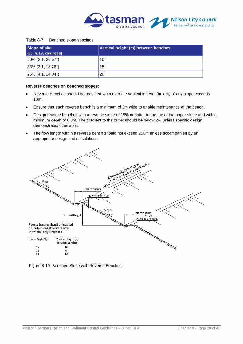
Table 8-7 Benched slope spacings
Slope of site
(%, h:1v, degrees)
Vertical height (m) between benches
50% (2:1, 26.57°) 10
33% (3:1, 18.26°) 15
25% (4:1, 14.04°) 20
Reverse benches on benched slopes:
Reverse Benches should be provided whenever the vertical interval (height) of any slope exceeds
10m.
Ensure that each reverse bench is a minimum of 2m wide to enable maintenance of the bench.
Design reverse benches with a reverse slope of 15% or flatter to the toe of the upper slope and with a
minimum depth of 0.3m. The gradient to the outlet should be below 2% unless specific design
demonstrates otherwise.
The flow length within a reverse bench should not exceed 250m unless accompanied by an
appropriate design and calculations.
Figure 8-19 Benched Slope with Reverse Benches

Nelson/Tasman Erosion and Sediment Control Guidelines – June 2019 Chapter 8 - Page 21 of 43
Key items to check as part of the regular inspection includes:
Repair or reinstate the bench slopes and reverse benches if destroyed by machinery movement
and after rainfall or storms.
Check the outfall of the reverse benches for erosion and repair if required. It may be necessary
to install a temporary flume or provide geotextile to line these exit points.
Remove any accumulated sediment within the reverse benches.
Decommissioning
Bench slopes are often permanent features and if they do need decommissioning then check the slope and
bench area for any rilling or scour, then add topsoil and stabilise.

Nelson/Tasman Erosion and Sediment Control Guidelines – June 2019 Chapter 8 - Page 22 of 43
8.2.7 Stabilised Entranceways
Definition and purpose
A stabilised entranceway is a stabilised pad of
aggregate (or equivalent) on a geotextile base located
at any entry or exit point of a construction site.
The purpose of a stabilised entranceway is to:
Provide for a specific site entrance way to avoid
multiple entranceways to a site.
Prevent site access points becoming sources of
sediment.
Keep adjacent road networks and associated
stormwater networks free of sediment.
To assist in minimising dust generation and
disturbance of areas adjacent to the road frontage
by providing a defined entry and exit point.
Some circumstances may require a formal wheel wash or a vibrating cattle grate system (shaker ramps) to
operate effectively (eg sites with river crossings, contaminated soils, etc). If installing wheel wash facilities,
ensure that full water management is considered and addressed to avoid further discharges. This will
require the installation of a formal sediment control device.
Conditions where practice applies
Stabilised entranceways apply:
At all points of construction site entry and exit (traffic should be limited to these accessways only).
Where necessary install entranceway in association with shaker ramps or wheel wash facilities as
close as possible to the boundary of the works area.
Limitations
Stabilised entranceways have the following limitations:
Stabilised entrance ways will reduce sediment movement but will not eliminate it completely. Care
needs to be taken to implement other management techniques (e.g. wheel wash, street sweeping) to
reduce the potential for vehicles to transport sediment on to road surfaces.
o The use of a wheel wash system in association with a stabilised entranceway can be expensive,
but if managed appropriately may provide much higher efficiencies in terms of sediment removal.
o On smaller sites where wheel wash systems may be impractical, regular sweeping of adjacent
roads and footpaths to keep them clear of debris and sediment may be needed, in particular at
the end of each working day and prior to rainfall events. Do not wash any sediment into the
stormwater system or any adjoining watercourse.
Do not locate stabilised entrance ways on steep slopes, in areas of concentrated flows, or next to
watercourses or stormwater catchpits. If steep slopes or catchpits are unavoidable, entranceways will
need specific detailed design to minimise sediment runoff and transportation, including catchpit inlet
protection to trap sediment for removal to an appropriate location.
Figure 8-20 Stabilised Entranceways

Nelson/Tasman Erosion and Sediment Control Guidelines – June 2019 Chapter 8 - Page 23 of 43
Key design criteria
Formal design of stabilised entranceways is generally not required (unless accessways are steep or
near watercourses) although the following design principles are required for them to be an effective
practice:
Once a suitable location for a stabilised entranceway has been determined, clear the area of
unsuitable material and grade the base to a smooth finish. Place woven geotextile over this area
ensuring this is appropriately pinned and overlapped as necessary (refer Figure 8-24)
Place aggregate from the construction site boundary extending for at least 10m according to the
specifications in Table 8-8; and
Contour the aggregate to suit the entrance point. Note that contouring can include a highpoint on the
grade to act as a barrier to water flowing out of the site.
Table 8-8 Stabilised entranceway specifications
Aggregate Size 100 – 105mm washed aggregate
Minimum Thickness 150mm or 1.5 times aggregate size
Minimum Length 10 metres
Minimum Width 4 metres
Provide drainage from the stabilised entranceway to an appropriate discharge point. This may require a
sediment control device (especially if a wheel wash is installed).
Stabilised entranceways do not necessarily need to be located at the permanent site entry/exit point;
however, consideration needs to be given to minimising the number of site entry and exit points.
Locate all stabilised entranceways so that vehicles cannot bypass these devices. Perimeter silt fences
or bunds may assist in achieving this requirement.
When used with a shaker ramp:
o A well-designed shaker ramp (eg prefabricated “cattle stop”) allows at least one full revolution of a
truck tyre. Two cattle stops should be placed one in front of the other to provide enough length.
o Stabilise the section of access road between
the shaker ramp and the sealed pavement
with aggregate.
o Ensure the runoff from the shaker ramp area
and/or wheel wash systems passes through
an appropriate sediment control device.
When used with a wheel wash:
o Ensure that a water collection and disposal
methodology (can include water
recirculation) is provided with wheel wash
facilities, and
o If wheel wash runoff cannot be disposed of
appropriately in the immediate vicinity, then
all overflow should be directed to a sediment
control device within the site.
Figure 8-18 Example of a shaker ramp in site
access point

Nelson/Tasman Erosion and Sediment Control Guidelines – June 2019 Chapter 8 - Page 24 of 43
Maintenance
Key items to check as part of the regular maintenance inspection includes:
Inspect weekly and after each rainfall event for general maintenance requirements.
Maintain the stabilised entrance way in a condition to prevent sediment from leaving the construction
site. This may require several applications of new aggregate during the life of the practice.
After each rainfall inspect any structure used to trap runoff from the stabilised entrance way and clean
out as is necessary.
Figure 8-19 Stabilised construction entrance showing progression of construction with filter fabric
underlay prior to stone placement
Figure 8-203 Stabilised entranceway

Nelson/Tasman Erosion and Sediment Control Guidelines – June 2019 Chapter 8 - Page 25 of 43
8.3 Soil Stabilisation Practices
A stabilised site is one that is resistant to erosion. Stabilisation is defined as applying measures such as
vegetative or structural practices that will protect exposed soil and minimise erosion. Common stabilisation
measures include spreading of aggregate, grassing (either with grass seed or hydroseed), revegetation,
applying mulch and the use of geotextiles.
Stabilisation techniques can be used as either a temporary or permanent measure against erosion. Some
techniques can provide instant protection (e.g. geotextiles) while others (e.g. grassing) may take some time
before the area is appropriately protected against erosion. In these situations, other erosion and sediment
controls may need to be retained in place until a sufficient level of stabilisation is achieved.
In relation to geotextiles, there are many and varied types and products. These range from those that
physically shed water through to those that incorporate seed and mulch and so encourage vegetative
growth, while protecting the bare soil against erosion.
Where vegetation is used, the disturbed surface is considered stabilised once an 80% vegetative cover has
been established over the entire exposed area. Permanently stabilised means vegetation that is self-
sustaining meaning it does not require ongoing intense maintenance or irrigation, past the initial
establishment phase, to ensure ongoing survival of at least 80% ground coverage. If this is unlikely to be
achievable due to site constraints, some other method of permanent stabilisation may be more appropriate.
It is important to consider the steepness and aspect of batter slopes, soil moisture, topsoil and nutrient
needs and the plant species used, to ensure the plants selected can cope with the specific site conditions
over the long term, particularly with hot dry summers and harsh Tasman sun.
Because vegetation is so effective in protecting soil surfaces and helping to reduce runoff, it can minimise
the erosion potential of a site and reduce the need for structural erosion and sediment controls. It is
therefore important to preserve as much of the existing vegetation as possible by limiting the extent of
works.
Further detail is provided below on the common measures used for stabilisation purposes including:
Top soiling and Grassing
Revegetation
Hydroseeding
Mulching
Turfing
Geotextiles
Dust Control.

Nelson/Tasman Erosion and Sediment Control Guidelines – June 2019 Chapter 8 - Page 26 of 43
8.3.1 Topsoiling and Grass Seeding
Definition and purpose
Grass seeding involves the planting and establishment of quick growing and/or perennial grass to provide
temporary and/or permanent stabilisation on exposed areas. The practice is often undertaken in
conjunction with the placement of topsoil.
Key fact
A site is NOT stabilised until 80% of the topsoil is covered with grass over 100% of the site.
Grass seed spread over the site and newly germinated seed is NOT considered Stabilisation of a
disturbed site.
The purpose of grassing is to provide either a short-
term or long-term cover for erosion control on
disturbed areas. The established vegetation protects
exposed soils from raindrop impact, reduces runoff
velocity and volume, binds soil particles together and
can also inhibit weed growth.
Topsoiling provides a suitable soil medium for
vegetative growth for erosion control while providing
some protection of the subsoil layer and also
increasing the absorption capacity of the soil.
Where grass is used for stabilisation, a disturbed
surface is considered stabilised with grass or other
vegetation once:
1. 80% vegetative cover has been established over
the 100% of the exposed area.
2. Permanently stabilised means the vegetation is self-sustaining - it does not require ongoing intense
maintenance or irrigation, past the initial establishment phase, to ensure ongoing survival of at least
80% ground coverage.
If this is unlikely to be achievable due to site constraints, some other method of permanent stabilisation
may be more appropriate.
It is important to consider the steepness and aspect of batter slopes, soil moisture, topsoil and nutrient
needs and the plant species used, to ensure the plants selected can cope with the specific site conditions
over the long term, particularly with hot dry summers and harsh Nelson/Tasman regions sun.
Figure 8-21 Vegetative stabilisation is an
effective erosion control practice
Nelson/Tasman Erosion and Sediment Control Guidelines – June 2019 Chapter 8 - Page 27 of 43
Conditions where practice applies:
The practice applies to any site where grass establishment is important for achieving stabilisation once
established or landscape purposes.
Temporary seeding: As a rapid-growing annual grass will provide a short-term cover. It is primarily used
where project works are still progressing but need temporary coverage.
Use on any cleared or unvegetated areas which are subject to erosion and will not be earth worked for
a period of 60 days up to a maximum duration of 12 months.
Temporary seeding is normally practised where the vegetative cover is required to be in place for less
than 12 months. In some circumstances mulching may be used as an alternative.
Utilise temporary seeding on short to medium-term stockpiles, the outside of sediment pond
embankments or diversion bunds, on cut and fill slopes, access/haul road embankments and any other
disturbed area that is likely to remain exposed and un-worked for less than 12 months. Permanent
seeding may be required for periods greater than 12 months.
Permanent seeding: The use of perennial grasses will provide permanent erosion protection to disturbed
areas following completion of the earthwork’s activity. Ideally, permanent grassing should be undertaken
progressively throughout the project as earthworks are finalised and brought to final grade.
This practice applies to any site where establishing permanent vegetation is important to protect bare
earth. It may also be used on rough graded areas that will not be brought to final grade for 12 months
or more.
Topsoiling: Topsoil provides the major zone for root development and biological activities. Topsoil is
important as it is a physically better rooting material, has more nutrients available and air and water is more
mobile through it than in clay subsoil layers. Topsoiling is recommended for sites where:
The texture and/or the organic component of the exposed subsoil or parent material cannot produce
and sustain adequate vegetative growth.
The soil material is so shallow that the rooting zone is not deep enough to support plants or furnish
continuing supplies of moisture and plant nutrients to sustain plants over the long term.
High quality vegetative cover is required to be established.
Dependent upon the site location and the soil structure that exists, soil tests for fertility and the need to add
further soil additives may provide benefits.
Limitations
Grass seeding has the following limitations:
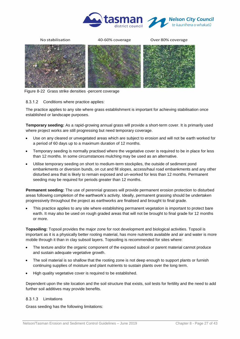
Figure 8-22 Grass strike densities -percent coverage

Nelson/Tasman Erosion and Sediment Control Guidelines – June 2019 Chapter 8 - Page 28 of 43
Establishing a protective vegetative sward is difficult during periods of low rainfall or during periods of
temperature extremes. Develop construction sequencing such that topsoiling and seeding occurs
during optimum periods (eg Aug-Nov, March-April) for vegetation establishment.
The newly established seed can be mobilised by intense rainfall and may require several applications
to achieve the appropriate stabilisation standard.
Topsoil alone is not considered stabilised and erosion/sediment control measures should be designed
to be in place until there is an appropriate density of grass strike (80% cover). Alternatively, other
stabilisation methods (e.g. mulching) may be used.
Key design criteria
For topsoiling and grass seeding use the following criteria:
Site preparation:
o Prior to seeding, ensure erosion and sediment control practices are still functioning.
o Final grading and shaping is not necessary for temporary seeding.
Seedbed preparation:
o It is important to prepare a good seedbed to ensure the success of establishing vegetation.
The seedbed should be friable, uniform and free of large clods and other objectionable
material. The soil surface should not be compacted or crusted.
o If the site has contaminated material, ensure that this is fully removed from the topsoil.
o Apply topsoil at a minimum depth of 100mm to allow for a friable surface.
o Topsoil is a valuable resource. When placing topsoil in stockpiles ensure that it is isolated by
the upslope diversion of clean water runoff, is stabilised appropriately and is not stored in
stockpiles greater than 2m in height to maintain soil structure and integrity.
Soil amendments:
o Apply fertiliser at the rate outlined in
o Table 8-9 or specific to the site in question. Confirm that this rate and type of fertiliser is
appropriate for site conditions with your fertiliser supplier before using.
o For large sites or unusual soil conditions, soil testing may be required as some soils may
require the addition of lime to improve pH and/or trace elements for grass growth.
Seed selection:
o Select the seed mixture from Table 8-9.
o Where topsoil is not used (eg recontouring vineyard blocks) only specialist colonising species
able to survive long term on subsoil should be used. Ryegrass and clover may still be used,
however strike rates can be low and growth slow and fertiliser is required.
o A mix of grass and pasture species (eg grasses and clovers) allows for natural succession for
better short and long term success (ie a rapidly growing grass provides initial cover which is
succeeded by clover which is better able to cope with long term site conditions (eg dryness or
infertility).
o Use only certified seed with a high purity and germination percentage from reputable suppliers.
Species selection need to consider the project’s ecological context and if undertaking
permanent seeding, be mindful of the final landscape plans.

Nelson/Tasman Erosion and Sediment Control Guidelines – June 2019 Chapter 8 - Page 29 of 43
Seed application:
o Apply seed uniformly at the rate outlined in Table 8-9. If hydro-seeding is required refer to
Section 8.3.2. Traditional agricultural techniques such as drill seeding, broadcast seeding or no
tillage are appropriate for establishing grass on areas flatter than 25%. Ensure the
methodology achieves a good seed-to-soil contact, thereby enhancing seed survival and
germination rates.
o For small areas hand-broadcasting and raking may also be used to apply seed and fertiliser.
o Apply and maintain fertiliser at the rate outlined in Table 8-9.
o If irrigation is required, deliver a volume at least equal to the evapotranspiration rate and
continue until natural rainfall provides the necessary soil moisture levels for plant survival.
o Ensure that the site conditions, and the time of the year are appropriate for germination and
vegetation establishment prior to undertaking this activity. This may involve the placement of
mulch and/or irrigation to achieve.
o In order to maximise germination and growth rates, the preferred seeding windows for both
temporary and permanent grassing are autumn and spring.
o Mulching as outlined in Section 8.3.3 should be undertaken in conjunction with the seeding
programme during dry or cold periods. This will protect both the seed and the soil, whilst also
providing a better microclimate for the germination and growth of grasses.
In all circumstances ensure that the seed and fertiliser application rates and mix is appropriate for your
site. Always discuss with your seed and fertiliser supplier prior to utilisation. Seek specific advice when
working near areas of high conservation value or very difficult soil conditions.
Table 8-9 Typical seed and fertiliser application rates
Application Typical seed mix
Application rates for:
Up to 20% slope
(5h:1v, 11.31°)
Greater than 20% slope
(5h1v, 11.31°)
Temporary Seeding Annual Ryegrass 20 kg/ha 30 kg/ha
Permanent Seeding1
Perennial Ryegrass 15 kg/ha 20 kg/ha
Cocksfoot 2 kg/ha 4 kg/ha
White clover
- pelleted or freshly inoculated with rhyzobia
(bacteria that fix nitrogen)
3 kg/ha 4 kg/ha
Maintenance fertiliser
6-12 weeks after seedling germination
12:10:10 (N:P:K) including trace elements
150kg/ha. 150kg/ha.
Note: if the area is to become fine lawn area, a commercial lawn mix should be used following the
producer’s recommendations with regard to application and fertilizer rates.
Any fertilizer application containing nitrogen should be carried out after seedling germination. Any
Fertiliser use will need to comply with the permitted activity discharge rules in the Tasman Resource
Management Plan or a resource consent is required.

Nelson/Tasman Erosion and Sediment Control Guidelines – June 2019 Chapter 8 - Page 30 of 43
Maintenance
The following are to be considered for maintaining topsoiling and grass seeding:
Check the condition of the topsoil on a regular basis and re-grade and/or replace where necessary so
as to always maintain the 100mm minimum depth of topsoil and appropriate surface roughening.
Heavy rainfall can wash new seeding away before full establishment of the grass. This is particularly
evident on smoother hard surfaces, steep slopes and overland flow paths. Where vegetation
establishment is unsatisfactory, the area will require a reapplication of seed or consideration will need
to be given to other stabilisation techniques.
Protect all re-vegetated areas from construction traffic and other activities such as the installation of drainage lines and utility services. If required, erect temporary barrier fencing and/or signage to restrict uncontrolled movement of equipment and vehicles onto grassed areas.

Nelson/Tasman Erosion and Sediment Control Guidelines – June 2019 Chapter 8 - Page 31 of 43
8.3.2 Hydroseeding
Definition and purpose
Hydroseeding is the application of seed, fertiliser and paper or wood pulp with water in the form of a slurry,
sprayed over an area to provide for re-vegetation.
The purpose of hydroseeding is to:
Establish grass and other vegetation on steep
and/or inaccessible areas.
Quickly establish vegetation. Hydroseeding as a
standalone measure does not achieve the definition
of stabilised although the practice will provide limited
protection from raindrop impact for a short time until
the grass is established.
Conditions where practice applies
This practice applies to any site where vegetation
establishment is important for stabilisation or landscape
purposes. Typically, it is used:
On critical areas such as steep slopes or batters and
exposed areas near watercourses that require a
more rapid germination and stabilisation than
conventional hand seeding.
On areas that may be difficult to establish by
conventional sowing methods (e.g. steep
embankments and areas with difficult access
Around diversion channels/bunds, where rapid
establishment of a protective vegetation cover is
required before introducing water flow.
Where hydroseeding of grass is used for stabilisation,
the disturbed surface is considered stabilised once a
minimum of 80% vegetative cover has been established
over the 100% of the exposed area. To be considered permanently stabilised, vegetation will have reached
a point that it is self-sustaining - meaning it does not require ongoing intense maintenance or irrigation, past
the initial establishment phase, to ensure ongoing survival of at least 80% ground coverage. If this is
unlikely to be achievable due to site constraints, some other method of permanent stabilisation may be
more appropriate.
It is important to consider the steepness and aspect of batter slopes, soil moisture, topsoil and nutrient
needs and the plant species used, to ensure the plants selected can cope with the specific site conditions
over the long term, particularly with hot dry summers and harsh Tasman sun.
Limitations
Hydroseeding has the following limitations:
Hydroseeding will require specialised equipment to apply and therefore there is a reliance on
experienced contractors and local knowledge to ensure that the seed mix is appropriate for the site and
conditions over both the short and long term.
Figure 8-236Hydroseed being applied to a vertical
face and the eventual stabilisation (photos
courtesy of Erosion Control Ltd).

Nelson/Tasman Erosion and Sediment Control Guidelines – June 2019 Chapter 8 - Page 32 of 43
Although there is an improved grass strike rate with hydroseeding, it is a more expensive option
compared with conventional grass seeding.
The newly established hydroseed can be mobilised by intense rainfall.
Hydroseeding is not suitable for permanent stabilisation of steep slopes that are too steep or dry to
maintain a healthy long-term vegetation cover. This can be a particular problem on north facing slopes
subject to intense summer sun and where there is little or no topsoil to assist with soil moisture
retention. If ongoing maintenance and irrigation is not planned and funded for such areas, then some
alternative form of permanent stabilisation will need to be implemented. Consideration should also be
given to modifying slopes to achieve grades more conducive to vegetation growth or use of hardy
colonising plant species which may tolerate the poor conditions and provide a suitable microclimate for
other species to be established at a later date.
Key design criteria
There are various hydroseed mixes which utilise soil
improvements, paper or wood pulp and in some
circumstances a binder to help seeds adhere to the
soil surface.
Use only experienced contractors.
preferably with good local knowledge.
For larger applications:
o a soil test should be done to determine rates
and whether an alkaline based fertiliser
should be used rather than an acid based
one.
Use seed mixes
o application and fertiliser rates recommended
by reputable hydroseeding companies to
ensure appropriate seed types and
application rates suitable to the specific site
conditions.
Maintenance
The following maintenance requirements are required for hydroseeding:
Heavy rainfall can wash new hydroseeding away before full establishment of the grass. This is
particularly evident on smoother hard surfaces and overland flow paths. Where vegetation
establishment is unsatisfactory, the area will require a reapplication of hydroseeding or consideration
will need to be given to other stabilisation techniques.
Apply additional fertiliser, as required, following hydroseeding contractor’s specifications
Protect all re-vegetated areas from construction traffic and other activities such as the installation of
drainage lines and utility services. If required, erect temporary barrier fencing and/or signage to restrict
uncontrolled movement of equipment and vehicles onto grassed areas.
Figure 8-247 Recently applied hydroseed
showing emergent grass growth

Nelson/Tasman Erosion and Sediment Control Guidelines – June 2019 Chapter 8 - Page 33 of 43
8.3.3 Mulching
Definition and purpose
Mulching is the application of a protective layer of hay or straw (or other suitable material) to the soil
surface to provide an instant surface protection.
The purpose of mulching is:
Providing a rapid stabilisation technique to
protect the soil surface from the forces of raindrop
impact and overland flow.
To help conserve soil moisture, maintain
temperatures, reduce runoff and erosion, prevent
soil crusting and promote the establishment of
desired vegetation.
Mulching for erosion control purposes is usually a
short to medium-term treatment. It can be used as a
stand-alone surface cover or in conjunction with a
seed and fertiliser grassing programme.
Although straw (wheat or barley) and hay are the commonly used materials, mulching can also include the
application of bark, wood residue and wood pulp spread over the surface of disturbed flatter ground. For
permanent stabilisation situations, pebbles or other aggregate may also be used as part of site landscaping.
Conditions where practice applies
Mulching can be used at any time where protection of the soil surface is desired, although the following
conditions are particularly applicable:
Where it is critical to achieve an immediate stabilised surface cover and to maintain this cover for the
short to medium term (three to five months). This includes stabilisation of areas that have not been
worked for a period of time although are proposed to be worked in the future.
Where a warmer microclimate is required to maintain soil temperatures and avoiding soil temperature
fluctuations, which in turn provide for appropriate conditions for seed germination and the establishment
of vegetation at most times of the year.
As an alternative to straw or hay mulch, bonded fibre
matrix products can be utilised (eg. hydroseed). These
are available from specific stabilisation specialists
however it is important to recognise that this surface
cover is not considered stabilised until sufficient grass
strike has occurred. This product is typically used on
steeper slopes (30% to 50%) (refer section 8.3.2).
Figure 8-258 Application of straw mulch as a
temporary ground cover
Figure 8-29 Recently applied mulch (Photo
courtesy of BOPRC)

Nelson/Tasman Erosion and Sediment Control Guidelines – June 2019 Chapter 8 - Page 34 of 43
Limitations
Mulching has the following limitations:
Mulching requires specialised equipment for large areas so that a uniform coverage is obtained. Hand
mulching can occur on smaller sites.
Both hay and straw mulch have a limited period of effectiveness. In general, hay will last for three months
and straw mulch up to five months before these materials become part of the soil matrix and effective
cover is lost.
Mulching may introduce weed species and, in some circumstances, may not be an appropriate measure
for the site. Care therefore needs to be taken to ensure that weed infestation of the mulched area does
not create a future issue.
If mulch is used as a temporary method of stabilisation to be followed by topsoiling and seeding,
consideration may be needed of whether the residual mulch requires removal or digging into topsoil to
ensure adequate grass strike is achieved.
Mulch can be dislodged by intense rainfall or very high winds.
Plant based or floatable mulch is not an appropriate cover in areas of concentrated flow paths or in
stream channel systems. Care is needed so the mulch does not block chemical treatment devices or
interrupt the operation of decants in ponds.
Key design criteria
Consider the following prior to applying mulch:
Apply straw or hay mulch as unrotted material at a rate of 6,000kg/ha. As a “rule of thumb” a 30mm
loose thickness (measured at time of application) is the required coverage and is considered to be in
a stabilised state. Ensure mulch material is relatively free of weeds and does not contain noxious
weed species. A list of noxious weeds can be obtained from Tasman District Council.
Avoid application in high winds, use dust suppression methods, if required, until mulch application
can be completed
Undertake hydro-mulch applications in accordance with the manufacturers’ specifications with a
minimum of 80% virgin or recycled wood. The application rate will range from 2,200kg/ha to
2,800kg/ha depending on the slope gradient. It should not be used on slope lengths greater than
150m.
Wood chip can be applied at rates of around 10,000kg/ha to 13,000kg/ha when available and feasible.
Bark mulch is generally slow to deteriorate but can affect soil nitrogen levels making it unavailable to
plants. It can also result in saps and tannins leaching and causing a change in pH. Wood chip should
not be used adjacent to watercourses and on steeper slopes as it can be washed away during flood
events blocking downstream areas and infrastructure.
If site conditions result in difficulties with the mulch material remaining on site (e.g. during windy
conditions), the mulch will need to be anchored.

Nelson/Tasman Erosion and Sediment Control Guidelines – June 2019 Chapter 8 - Page 35 of 43
Forms of anchoring comprise:
o Crimping – using a tractor drawn implement designed to punch and anchor mulch into the top 5cm of the soil profile. On sloping land, crimping should be done on the contour whenever possible.
o Binders or tackifiers can be applied directly as the mulch is being distributed at an application rate that matches the manufacturers’ specifications for that specific binder.
Maintenance
The following maintenance requirements are required
when mulch is used:
Inspect after each rainfall event or periods of excessively strong winds, and repair or replace any areas of damaged cover.
Construction equipment can cause disturbance to stabilised areas and may require the erection of a temporary barrier and/or signage to restrict the movement of equipment and vehicles onto mulched areas.
Maintain 100% surface cover for optimal protection and a reapplication will be required when the integrity and/or surface density has declined.
Figure 8-30 Straw mulch being crimped into ground
to reduce windblown potential
Figure 8-31 Well applied mulch and vegetative cover –
photo courtesy of BOPRC and Ridley Dunphy
Environmental Ltd

Nelson/Tasman Erosion and Sediment Control Guidelines – June 2019 Chapter 8 - Page 36 of 43
8.3.4 Turfing
Definition and purpose
Turfing is the establishment and permanent stabilisation of disturbed areas by laying a continuous cover of
already grown grass turf.
The purpose of the practice is to provide rapid
stabilisation by the placement of vegetative
cover to stabilise exposed areas.
Turfing (“instant lawn”) may also be used to
establish a vegetative filter or buffer along
footpaths, driveways, kerbs and channels. The
practice provides instant results from a visual
and erosion control perspective.
Turf is considered to provide instant
stabilisation as it protects exposed soil from
rainfall impact and overland flow, however, to
be considered as permanently stabilised the
turf should be firmly rooted to the original
ground surface and retain at least an 80%
vegetative cover over the entire exposed area. The turf vegetation will have reached a point that it is self-
sustaining - meaning it does not require ongoing intense maintenance or irrigation, past the initial
establishment phase, to ensure ongoing survival of at least 80% ground coverage (unless this has been
included in ongoing maintenance considerations – eg in a residential situation). If this is unlikely to be
achievable due to site constraints, some other method of permanent stabilisation may be more appropriate.
It is important to consider the steepness and aspect of batter slopes, soil moisture, topsoil and nutrient
needs and the plant species used, to ensure the plants selected can cope with the specific site conditions
over the long term, particularly with hot dry summers and harsh Tasman sun.
Conditions where practice applies
This practice is typically used where:
Critical erosion prone areas on the site that cannot be stabilised by conventional sowing or other stabilisation methods.
Runoff diversion channels and other areas of concentrated flow where velocities will not exceed the specifications for a grass lining.
Areas around grass stormwater inlets, swales, embankments, road berms and other areas that require immediate grass cover for landscaping purposes.
Limitations
Turfing can be a relatively expensive option to achieve
a stabilised surface although it has the dual advantage
of providing erosion control, as well as being suitable
for landscaping of a feature.
Figure 8-3326 Turf being applied for a swale outfall
Figure 8-32 Turf being applied to provide immediate
ground cover

Nelson/Tasman Erosion and Sediment Control Guidelines – June 2019 Chapter 8 - Page 37 of 43
Key design criteria
Appropriate criteria for turfing are:
The following criteria should be met for turf placement:
o Rake soil surface to break crust prior to laying turf.
o During periods of high temperature, lightly irrigate the soil immediately prior to placement. Do
not install on hot, dry soil, compacted clay, frozen soil, gravel or soil that has been treated
with pesticides as this can damage the roots of the turf and prevent root growth into the
original ground surface.
o Turf strips should be laid on the contour, never up and down the slope, starting at the bottom
of the slope and working up. Install strips of turf with their longest dimension perpendicular to
the slope and stagger the joints.
o Do not stretch or overlap turf strips.
o All joins should be butted tightly to prevent voids which would cause drying of the roots. Also,
open spaces may cause erosion.
o On slopes steeper than 3H:1V, secure turf to surface soil with wood pegs, wire stables or
split shingles. Use of ladders will facilitate work on steep slopes and prevent damage to the
turf.
Roll and tamp turf immediately following placement to ensure solid contact of root mat and soil
surface.
Care needs to be taken to ensure that flow velocities travelling over the turfed area will not cause
erosion. In these circumstances which often relate to steeper areas, turf reinforced with geotextiles
should be considered. Refer to manufacturers’ specifications for flow velocities applicable for the
various geotextiles.
Maintenance
The following maintenance is required for turfing:
Water daily during the first week of laying the turf unless there is adequate rainfall.
Check to ensure that the turf is firmly rooted to the original ground surface. Do not mow the area until
the turf is firmly rooted.
Apply fertiliser as required in accordance with supplier’s specifications.

Nelson/Tasman Erosion and Sediment Control Guidelines – June 2019 Chapter 8 - Page 38 of 43
8.3.5 Geotextiles and erosion control blankets
Definition and purpose
Geotextiles, plastic covers and erosion control blankets are used to stabilise disturbed soil areas and
protect soils from erosion by wind or water.
The purpose of the practice is to:
Instantly reduce the erosion potential of the
disturbed areas and/or reduce or eliminate
erosion on critical sites.
Permanently or temporarily control erosion.
Enable revegetation of difficult sites (eg steep
areas where topsoil is unstable.
Geotextiles are generally considered to provide
instant temporary stabilisation as they protect
exposed soil from rainfall impact and overland flow.
Conditions where practice applies
These measures are used when disturbed soils may
be particularly difficult to stabilise, including the
following situations:
In critical erosion-prone areas such as sediment retention pond outlets and inlet points.
In channels where the design flow produces tractive shear forces greater than existing soils can
withstand which leads to erosion of the soil surface.
On a temporary basis in areas where there is inadequate space to install sediment controls, so that
good erosion control is vital.
In areas that may be slow to establish an adequate permanent vegetative cover. In this situation, the
geotextile provides an early protective layer. Maintenance issues for the vegetation component are dealt
with in section 8.3.1.
On short steep slopes, batters, or stockpiles during periods of inactivity on the site.
In situations where tensile and shear strength characteristics of conventional mulches limit their
effectiveness in controlling runoff velocities, such as overland flow paths.
In areas where the downstream environment is of high value and rapid stabilisation is required.
Limitations
The practice has the following limitations:
Blankets and mats are generally not suitable for excessively rocky sites, or areas where the final
vegetation will be mowed as the staples and netting can catch in mowers.
Blankets and mats that are removed should be disposed of to an approved location, prior to application
of permanent soil stabilisation measures, unless they are specifically designed for use with permanent
revegetation and made of 100% natural fibres which will biodegrade over time.
Geotextiles do not generally provide the same level of benefit to soil quality as many of the traditional
plant-based mulches (e.g. straw mulch).
Figure 8-34 Erosion control blanket for slope
protection. Notice grass growing through blanket
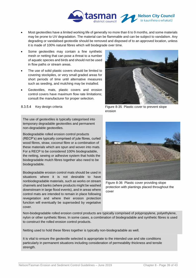
Nelson/Tasman Erosion and Sediment Control Guidelines – June 2019 Chapter 8 - Page 39 of 43
Most geotextiles have a limited working life of generally no more than 6 to 9 months, and some materials
may be prone to UV degradation. The material can be flammable and can be subject to vandalism. Any
degrading or vandalised geotextile should be removed and disposed of to an approved location, unless
it is made of 100% natural fibres which will biodegrade over time.
Some geotextiles may contain a fine synthetic
mesh or netting that can pose a threat to a number
of aquatic species and birds and should not be used
in flow paths or stream areas.
The use of solid plastic covers should be limited to
covering stockpiles, or very small graded areas for
short periods of time until alternative measures
such as seeding, and mulching may be installed.
Geotextiles, mats, plastic covers and erosion
control covers have maximum flow rate limitations;
consult the manufacturer for proper selection.
Key design criteria
The use of geotextiles is typically categorised into
temporary degradable geotextiles and permanent
non-degradable geotextiles.
Biodegradable rolled erosion control products
(RECP’s) are typically comprised of jute fibres, curled
wood fibres, straw, coconut fibre or a combination of
these materials which are spun and woven into mats.
For a RECP to be considered 100% biodegradable,
the netting, sewing or adhesive system that holds the
biodegradable mulch fibres together also need to be
biodegradable.
Biodegradable erosion control mats should be used in
situations where it is not desirable to have
nonbiodegradable materials, such as works on stream
channels and banks (where products might be washed
downstream in large flood events), and in areas where
control mats are intended to remain in place following
revegetation and where their erosion protection
function will eventually be superseded by vegetative
cover.
Non-biodegradable rolled erosion control products are typically comprised of polypropylene, polyethylene,
nylon or other synthetic fibres. In some cases, a combination of biodegradable and synthetic fibres is used
to construct the rolled erosion control products.
Netting used to hold these fibres together is typically non-biodegradable as well.
It is vital to ensure the geotextile selected is appropriate to the intended use and site conditions
particularly in permanent situations including consideration of permeability thickness and tensile
strength.
Figure 8-35 Plastic cover to prevent slope
erosion
Figure 8-36 Plastic cover providing slope
protection with plantings placed throughout the
cover

Nelson/Tasman Erosion and Sediment Control Guidelines – June 2019 Chapter 8 - Page 40 of 43
For specific construction and design specifications and to ensure that the appropriate product is used for
the conditions, refer to the manufacturers themselves and the product information sheets supplied by the
manufacturer.
Key installation considerations
All natural and synthetic geotextile products will need to be installed to the manufacturers’ specifications
(including site preparation) to achieve:
Good anchorage, keying-in and overlap of geotextiles to ensure complete and direct contact with soil
and that they are not damaged, undercut or removed by wind or runoff.
Good strike rate and growth of seeded or planted vegetation undertaken in conjunction with
geotextile use.
Good erosion control protection is achieved for the required length of time before works are finished
and permanent stabilisation achieved
Figure 8-27 Geotextile Design on slopes (figure courtesy of Auckland Councils’)

Nelson/Tasman Erosion and Sediment Control Guidelines – June 2019 Chapter 8 - Page 41 of 43
Maintenance
Areas treated with geotextiles and other synthetics should be inspected daily and after each rainfall event.
They should be maintained to provide appropriate erosion control and be repaired, reapplied or replaced if
damage occurs or if the area becomes exposed or exhibits visible erosion. The maintenance aspects to
look for include:
Lifting geotextile caused by anchor failure or vegetation growing up under the fabric
Rilling caused by water flowing beneath the geotextile
Torn geotextile, missing pins or other damage caused by high winds, machinery or vandalism
Any areas of geotextile damaged or dislodged in any way should be repaired or replaced.
If required, erect a temporary barrier and/or signage and fencing to restrict uncontrolled movement of
equipment and vehicles onto treated areas.
Decommissioning
When decommissioning geotextiles and other synthetics undertake the following:
If geotextile is temporary, remove it and stabilise the area using a permanent stabilisation method.
If geotextile is part of a permanent solution (eg as part of a revegetation programme), ensure good
stabilisation occurs (ie. at least 80% coverage), otherwise geotextile should be renewed, or another
stabilisation method should be employed until long term permanent stabilisation is achieved.
Biodegradable systems can be left to decompose, however some other long-term stabilisation (eg
revegetation) should be achieved before the erosion protection provided by the geotextile is lost.
Figure 8-28 Geotextile Design on outfalls (figure courtesy of Auckland Councils’)
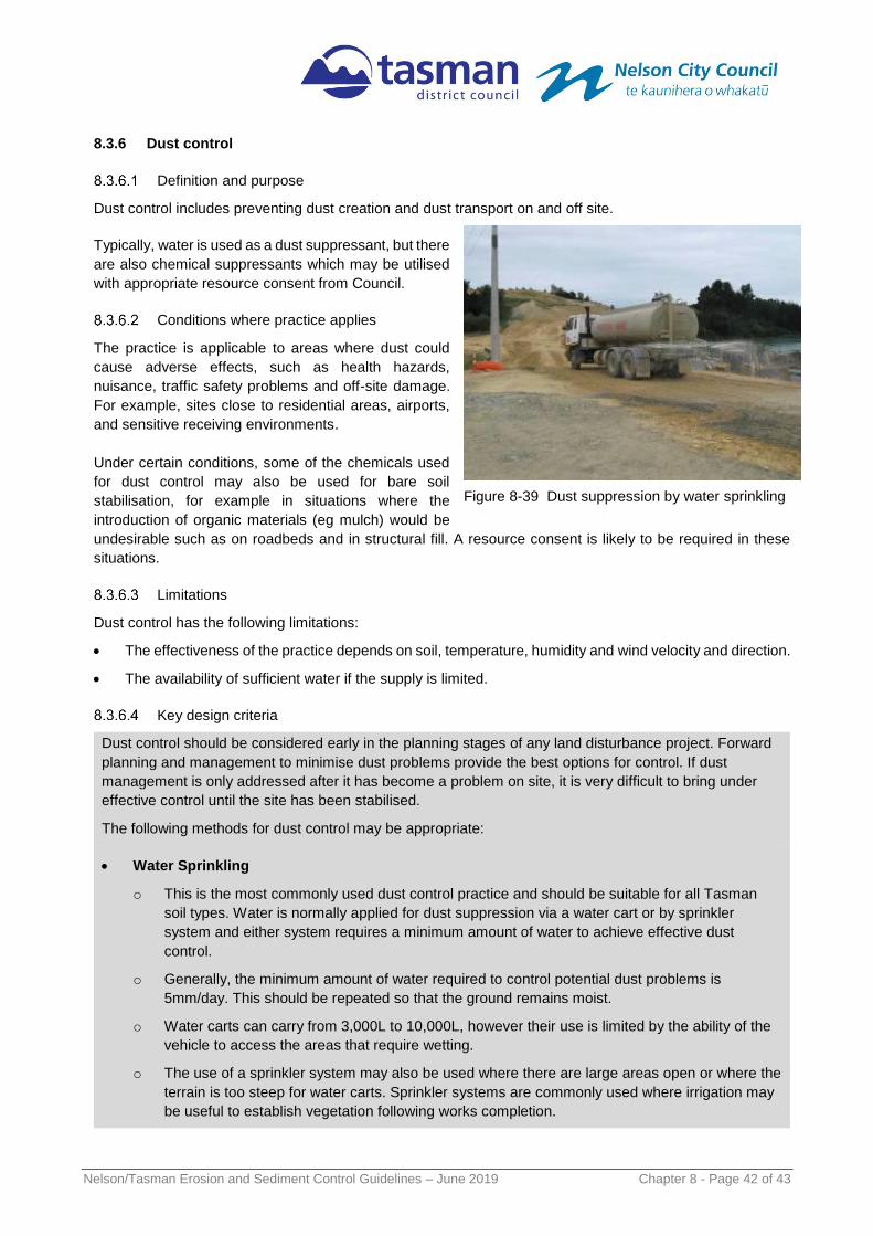
Nelson/Tasman Erosion and Sediment Control Guidelines – June 2019 Chapter 8 - Page 42 of 43
8.3.6 Dust control
Definition and purpose
Dust control includes preventing dust creation and dust transport on and off site.
Typically, water is used as a dust suppressant, but there
are also chemical suppressants which may be utilised
with appropriate resource consent from Council.
Conditions where practice applies
The practice is applicable to areas where dust could
cause adverse effects, such as health hazards,
nuisance, traffic safety problems and off-site damage.
For example, sites close to residential areas, airports,
and sensitive receiving environments.
Under certain conditions, some of the chemicals used
for dust control may also be used for bare soil
stabilisation, for example in situations where the
introduction of organic materials (eg mulch) would be
undesirable such as on roadbeds and in structural fill. A resource consent is likely to be required in these
situations.
Limitations
Dust control has the following limitations:
The effectiveness of the practice depends on soil, temperature, humidity and wind velocity and direction.
The availability of sufficient water if the supply is limited.
Key design criteria
Dust control should be considered early in the planning stages of any land disturbance project. Forward
planning and management to minimise dust problems provide the best options for control. If dust
management is only addressed after it has become a problem on site, it is very difficult to bring under
effective control until the site has been stabilised.
The following methods for dust control may be appropriate:
Water Sprinkling
o This is the most commonly used dust control practice and should be suitable for all Tasman
soil types. Water is normally applied for dust suppression via a water cart or by sprinkler
system and either system requires a minimum amount of water to achieve effective dust
control.
o Generally, the minimum amount of water required to control potential dust problems is
5mm/day. This should be repeated so that the ground remains moist.
o Water carts can carry from 3,000L to 10,000L, however their use is limited by the ability of the
vehicle to access the areas that require wetting.
o The use of a sprinkler system may also be used where there are large areas open or where the
terrain is too steep for water carts. Sprinkler systems are commonly used where irrigation may
be useful to establish vegetation following works completion.
Figure 8-39 Dust suppression by water sprinkling

Nelson/Tasman Erosion and Sediment Control Guidelines – June 2019 Chapter 8 - Page 43 of 43
o A reliable source of water is required and can be sourced from sediment retention ponds or
authorised water takes (bore, stream, lake or municipal water supply). Approval to take from
these supplies may be required from Council.
Adhesives and Binders
o Adhesives and Binders are generally synthetic materials that are applied to the soil surface to
act as binding agents and are for use on mineral soils only. Specific application rates apply
depending on the type and use.
o In the Tasman district a resource consent is required to use any chemicals for dust control.
Barriers
o Place barriers such as solid board fences, fences with dust suppression jets, at right angles to
the prevailing air currents.
o These should be placed at intervals of approximately 10 times their height.
Mulches and Vegetation
o Refer to sections 8.3.1 to 8.3.4 for the specifications on mulching and grass establishment.
Management Practices
Where a Dust Management Plan is required by a resource consent it should generally include the following:
Soil characteristics of the site and whether the timing/staging of operations will assist in dust reduction
Wind direction
Methods used to reduce vehicle speeds
Operational considerations – staging of area, progressive stabilisation etc
Types of measures used – water, vegetation and/or chemical suppressants;
Resource Consent conditions to be met
Contingency measures in place for severe wind problems (e.g. ceasing works if the primary method of
control is not effective for the wind conditions)
Signage and indications of contact numbers for dust complaints.
A dust management plan may be included as part of the site Erosion and Sediment Control Plan.
Maintenance
The following maintenance requirements to be considered:
Periodically inspect areas that have been protected to ensure adequate coverage.
Dust monitoring should become part of your general site monitoring and may also be required as a
condition of consent for the project.
Decommissioning
Prior to decommissioning dust controls ensure that good site stabilisation occurs.