Embed Size (px)
Citation preview

١
Chapter 7 SIMPLE CONNECTIONS
7.1 INTRODUCTORY CONCEPTS
Connection of structural steel members are of critical importance.
An inadequate connection has been the cause of numerous failures.
Most structural failures are the result of poorly designed or detailed connection.
Modern steel structures are connected by welding or bolting or by a combination of both.
Until fairly recently, connections were either welded or riveted.
Today the wide spread use of high strength bolts has rended the rivet obsolete in civil engineering structures.
There are several reasons for this change such as:
• No need to skilled workers in bolts connections.
• Riveting operations very noisy.
A welded connection is often simpler in its concept and requires few, if any holes.
Skilled workers are required for welding, and inspection can be difficult and costly.
There are different types of bolted connections. They can be categorized based on the type of
loading.
Tension member connection and splice. It subjects the bolts to forces that tend to shear the shank of the fastener.

٢
Beam end simple connection. It subjects the bolts to forces that tend to shear
Hanger connection. The hanger connection puts the bolts in tension.
Some connections produce both shear and tension in the upper rows of fasteners ( why in the upper)
General types of connections:
A- Simple connections:
The resultant of loads to be resisted passes through the center of gravity of the connection. In this case,
each part of the connectin is assumed to resist an equal share of the load.
The load capacity of connection = fastener capacity * no. of fastener or
The load capacity of connection = weld capacity per inch * length of weld.
B- Eccentrically connection
The line of action of the load does not act through the center of gravity of the connection.

٣
7.2- BOLTED SHEAR CONNECTIONS: We want to design the bolted shear connections so that the factored design strength (φ Rn) is greater than or equal to the factored load. So, we need to examine the various possible failure modes and calculate the corresponding design strengths. Possible failure modes are:
• Shear failure of the bolts
• Failure of member being connected due to fracture or block shear or ….
• Edge tearing or fracture of the connected plate
• Tearing or fracture of the connected plate between two bolt holes
• Excessive bearing deformation at the bolt hole
Failure modes of bolts in shear Shear failure of bolts Average shearing stress in the bolt =
• P is the load acting on an individual bolt
• A is the area of the bolt and db is its diameter
Strength of the bolt =
Hole bearing
Hole tearout
Bolt shear

٤
• where fv = shear yield stress = 0.6Fy
Bolts can be in single shear or double shear as shown below When the bolt is in double shear, two cross-sections are effective in resisting the load.
The bolt in double shear will have the twice the shear strength of a bolt in single shear.
(a) Single shear (b) Double shear
Failure of connected member
• We have covered this in detail in Ch. 3 on tension members
• Member can fail due to tension fracture or block shear. Bearing failure of connected/connecting part due to bearing from bolt holes
Hole is slightly larger than the fastener and the fastener is loosely placed in hole.
Contact between the fastener and the connected part over approximately half the circumference of the
fastener.
As such the stress will be highest at the radial contact point (A). However, the average stress can be
calculated as the applied force divided by the projected area of contact.
Average bearing stress fp = P/(db t), where P is the force applied to the fastener.

٥
The bearing stress state can be complicated by the presence of nearby bolt or edge. The bolt spacing
and edge distance will have an effect on the bearing stress.
7.3 – BEARING STRENGTH, SPACING, AND EDGE-DISTANCE REQUIREMENTS
Bearing stress effects are independent of the bolt type because the bearing stress acts on the connected
plate not the bolt.
A possible failure mode resulting from excessive bearing close to the edge of the connected element is
shear tear-out as shown below. This type of shear tear-out can also occur between two holes in the
direction of the bearing load.
Where

٦
• 0.6 Fu is the shear fracture stress of the connected part.
• Lc is the distance from edge of hole to edges of connected part
• t is the thickness of the connected part.
To prevent excessive deformation of the hole, an upper limit is placed on the bearing load. This upper
limit is proportional to the fracture stress times the projected bearing area, or
Where
C is a constant, d is the bolt diameter and t is the thickness of the connected part.
If deformation is not a concern then C = 3, If deformation is a concern then C=2.4 C = 2.4
corresponds to a deformation of 0.25 in.
Finally, the equation for the bearing strength of a single bolt is φRn
Where, φ = 0.75 and Rn = 1.2 Lc t Fu < 2.4 db t Fu
Lc is the clear distance in the load direction, from the edge of the bolt hole to the edge of the adjacent
hole or to the edge of the material.
This relationship can be simplified as follows:
The upper limit will become effective when 1.2 Lc t Fu = 2.4 db t Fu
i.e., the upper limit will become effective when Lc = 2 db
If Lc < 2 db, Rn = 1.2 Lc t Fu
If Lc > 2 db, Rn = 2.4 db t Fu

٧
DESIGN PROVISIONS FOR BOLTED SHEAR CONNECTIONS
In a simple connection, all bolts share the load equally.
In a bolted shear connection, the bolts are subjected to shear and the connected plates are
subjected to bearing stresses.
The shear strength of all bolts = shear strength of one bolt * number of bolts
The bearing strength of the connected plates can be calculated using equations given by AISC
specifications.
The tension strength of the connecting / connected plates can be calculated as discussed earlier in
Chapter 3.
Spacing and Edge-Distance Requirements
Chapter J of the AISC Specifications focuses on connections.
Section J3 focuses on bolts and threaded parts
AISC Specification J3.3 indicates that the minimum distance (s) between the centers of bolt holes is
2.67 db. A distance of 3db is preferred.
AISC Specification J3.4 indicates that the minimum edge distance (Le) from the center of the bolt to the
edge of the connected part is given in Table J3.4 as a function of bolt size and type of edge - sheared
edges, edges of rolled shapes, and gas cut edges.
AISC Specification J3.5 indicates that the maximum edge distance for bolt holes is 12 times the
thickness of the connected part (but not more than 6 in.). The maximum spacing for bolt holes is 24
٨
times the thickness of the thinner part (but not more than 12 in.).
Specification J3.6 indicates that the design tension or shear strength of bolts is φ FnAb
• Table J3.2 gives the values of φ and Fn
• Ab is the unthreaded area of bolt (nominal bolt area).
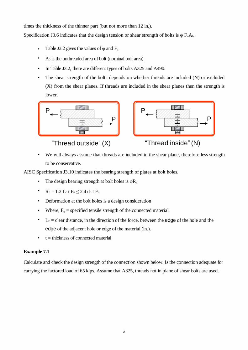
• In Table J3.2, there are different types of bolts A325 and A490.
• The shear strength of the bolts depends on whether threads are included (N) or excluded
(X) from the shear planes. If threads are included in the shear planes then the strength is
lower.
PP
“Thread outside” (X)
PP
“Thread inside” (N) • We will always assume that threads are included in the shear plane, therefore less strength
to be conservative.
AISC Specification J3.10 indicates the bearing strength of plates at bolt holes.
• The design bearing strength at bolt holes is φRn
• Rn = 1.2 Lc t Fu ≤ 2.4 db t Fu
• Deformation at the bolt holes is a design consideration
• Where, Fu = specified tensile strength of the connected material
• Lc = clear distance, in the direction of the force, between the edge of the hole and the
edge of the adjacent hole or edge of the material (in.).
• t = thickness of connected material
Example 7.1
Calculate and check the design strength of the connection shown below. Is the connection adequate for
carrying the factored load of 65 kips. Assume that A325, threads not in plane of shear bolts are used.

٩
Solution
Step I. Shear strength of bolts
The design shear strength of one bolt in shear = φ Fn Ab = 0.75 x 60 x π x 0.752/4
φ Fn Ab = 19.9 kips per bolt (See Table J3.2)
Shear strength of connection = 4 x 19.9 = 79.5 kips > 65 kips
Step II. Minimum edge distance and spacing requirements
See Table J3.4, minimum edge distance = 1 in. for rolled edges of plates and 1.25 in for sheared edges.
The given edge distances (1.25 in.) > both. Therefore, minimum edge distance requirements are satisfied.
Minimum spacing = 2.67 db = 2.67 x 0.75 = 2.0 in.
Preferred spacing = 3.0 db = 3.0 x 0.75 = 2.25 in.
The given spacing (2.5 in.) > 2.25 in. Therefore, spacing requirements are satisfied.
Step III. Bearing strength at bolt holes.
Bearing strength at bolt holes in connected part (5 x ½ in. plate)
At edges, Lc = 1.25 - hole diameter/2 = 1.25 - (3/4 + 1/16)/2 = 0.844 in.
φRn = 0.75 x (1.2 Lc t Fu) = 0.75 x (1.2 x 0.844 x 0.5 x 58) = 22.02 kips
But, φRn ≤ 0.75 (2.4 db t Fu) = 0.75 x (2.4 x 0.75 x 0.5 x 58) = 39.15 kips
Therefore, φRn = 22.02 kips at edge holes
At other holes, s = 2.5 in, Lc = 2.5 - (3/4 +1/16) = 1.688 in.
φRn = 0.75 x (1.2 Lc t Fu) = 0.75 x (1.2 x 1.688 x 0.5 x 58) = 44.05 kips
But, φRn ≤ 0.75 (2.4 db t Fu) = 39.15 kips. Therefore φRn = 39.15 kips

١٠
Therefore, φRn = 39.15 kips at other holes
Therefore, bearing strength for the tension member = 2 x 22.02 + 2 x 39.15 = 122.34 kips
Bearing strength at bolt holes in gusset plate (3/8 in. plate)
At edges, Lc = 1.25 - hole diameter/2 = 1.25 - (3/4 + 1/16)/2 = 0.844 in
φRn = 0.75 x (1.2 Lc t Fu) = 0.75 x (1.2 x 0.844 x 0.375 x 58) = 16.52 k
But, φRn ≤ 0.75 (2.4 db t Fu) = 0.75 x (2.4 x 0.75 x 0.375 x 58) = 29.36 kips
Therefore, φRn = 16.52 kips at edge holes
At other holes, s = 2.5 in, Lc = 2.5 - (3/4 +1/16) = 1.688 in.
φRn = 0.75 x (1.2 Lc t Fu) = 0.75 x (1.2 x 1.688 x 0.375 x 58) = 33.04 kips
But, φRn ≤ 0.75 (2.4 db t Fu) = 29.36 kips
Therefore, φRn = 29.36 kips at other holes
Therefore, bearing strength for the gusset plate = 2 x 16.52 + 2 x 29.36 = 91.76 kips
Bearing strength of the connection is the smaller of the bearing strengths = 91.76 kips
Bearing and shear strength, spacing and edge distance requirements are satisfied.
7.4 COMMON BOLTS
Common bolts (unfinished bolts) are designated as ASTM A307.
Rn = Fv * Ab
Where
Fv is the ultimate shearing stress
Ab is the cross sectional area of the unthreaded part of the bolt
The ultimate shearing stress is given in AISC Table J3.2 as 24 ksi.
Example7.2
Determine the design strength of the connection shown in the Figure based on shear and bearing.
Solution
Shear strength:
For single bolt:
PL7/16*2.50 3/8" gusset PL
A36 steel, 3/4" diam. A307 bolts 1.5" 1.5" 3.0"

١١
φRn = φ* Fv*Ab = 0.75 * 24 * (π (0.75)2)/4 = 7.952 kips
For two bolts:
φRn = 2 * 7.952 = 15.9 kips.
Bearing strength
Since the edge distance are the same for both the tension member and the gusset plate, the bearing
strength of the gusset plate will control because it is thinner than the tension member.
Hole diameter (h) = d + 1/16 = 0.75 + 3/4 = 13/16 in.
For the hole nearest the edge of the gusset plate,
Lc = Le – h/2 = 1.5 – 13/32 = 1.094 in.
φRn = φ* (1.2 Lc t Fu) = 0.75 * 1.2 * 1.094 * 3/8 * 58 = 21.42 kips.
But, φRn ≤ 0.75 (2.4 db t Fu) = 0.75 * 2.4 * 0.75 * 3/8 * 58 = 29.36 kips> 21.42 kips.
Use φRn = 21.42 for this bolt.
For the other hole:
Lc = s – h = 3 – 13/16 = 2.188 in
φRn = φ* (1.2 Lc t Fu) = 0.75 * 1.2 * 2.188 * 3/8 * 58 = 42.83 kips
But, φRn ≤ 0.75 (2.4 db t Fu) = 0.75 * 2.4 * 0.75 * 3/8 * 58 = 29.36 kips < 42.83 kips
Use φRn = 29.36 for this bolt.
The bearing strength for the connection is
φRn = 21.42 + 29.36 = 508 kips
Bearing strength > shear strength
So shear strength controls and the strength of the connection is
φRn = 159 kips.
Note
All spacing and edge distance requirements are satisfied. For a sheared edge, the minimum edge
distance required by the AISC is 1.25 inches, and this requirement is satisfied in both directions. The
bolt spacing s is 3 inches, which is greater than 2.6667d = 2.667 * 0.75 = 2.0 in.
7.5 HIGH-STRENGTH BOLTS
High strength bolts are available in two grades:
• ASTM A325 bolts (made from a heat-treated medium carbon steel)
• ASTM A490 bolts (also made from a heat-treated but from alloy steel)
A490 bolts have a higher ultimate tensile strength than A325 and are assigned a higher nominal
strength.
A490 bolts are more expensive than A325, but usually fewer are required.

١٢
7.6 SHEAR STRENGTH OF HIGH-STRENGTH BOLTS
The design shear strength of both A325 and A490 bolts is φRn
Where the resistance factor, φ, is 0.75.
The shear stress of A325 and A490 bolts depends on whether the threads are in a plane of shear.
Rather than use a reduced cross-sectional area when the threaded portion is subjected to shear, the
ultimate shearing stress is multiplied bu a factor of 0.75 (the approximate ratio of threaded area to
unthreaded area).
The strengths are given in AISC Table J3.2 and are summarized as:
Fastener Nominal Shear Strength
Rn = Fv * Ab
A325, threads in plane of shear 48 Ab
A325, threads not in plane of shear 60 Ab
A490, threads in plane of shear 60 Ab
A490, threads not in plane of shear 75 Ab
AISC Table J3.2 refers to threads in a plane of shear as "included in the shear planes" and refer to
threads not in a plane of shear as "excluded from shear planes"
Note:
When it is not known whether the threads are in the plane of shear, assume that they are and use the
lower shear strength.
Example 7.3
Design a double angle tension member and a gusset plated bolted connection
system to carry a factored load of 100 kips. Assume A572 Grade 50 (50 ksi yield stress) material for
the double angles and the gusset plate. Assume A325 bolts. Note that you have to design the double
angle member sizes, the gusset plate thickness, the bolt diameter, numbers, and spacing.
Solution
Step I. Design and select a trial tension member
• See Table 3-7 of the AISC manual.
• Select 2L 3.5 x 2.5 x 1/4 with φPn = 130.5 kips (yielding) >100 kips
Step II. Select size and number of bolts
• The bolts are in double shear for this design (may not be so for other designs)

١٣
• Use 3/4 in. A325 bolts in double shear
• Ab = (πd2/4) = (π * (0.75)2)/4 =0.4418 in2.
• The design shear strength per bolt is therefor
• φRn = 0.75 * 2 * 0.4418 * 48 = 31.8 kips
• Number of bolts = 100 / 31.8 = 3.15 bolts
• Use four bolts
• The design shear strength is
• φRn = 31.8 * 4 = 127.2 kips > 100 kips
Step III. Design edge distance and bolt spacing
• See Table J3.4
• The minimum edge distance = 1 in. for 3/4 in. diameter bolts in rolled edges.
• Select edge distance = 1.25 in.
• See specification J3.5
• Minimum spacing = 2.67 db = 2.0 in.
• Preferred spacing = 3.0 db = 2.25 in.
• Select spacing = 3.0 in., which is greater than preferred or minimum spacing
Step IV. Check the bearing strength at bolt holes in angles
Assume that the four bolts were arranged in one line in the long leg.
Bearing strength at bolt holes in angles
Angle thickness = 3/8 in.
Bearing strength at the edge holes (Le = 1.25 in.)
Lc = Le – h/2 = 1.25 – (3/4 + 1/16)/2 = 0.84375 in.
φRn = φ* (1.2 Lc t Fu) = 0.75 * 1.2 * 0.84375 * 1/4 * 65 = 12.34 kips.
But, φRn ≤ 0.75 (2.4 db t Fu) = 0.75 * 2.4 * 0.75 * 1/4 * 65 = 21.93 kips> 12.34 kips.
Use φRn = 12.34 for this bolt.
For the other hole:
Lc = s – h = 3 – 13/16 = 2.188 in
φRn = φ* (1.2 Lc t Fu) = 0.75 * 1.2 * 2.188 * 1/4 * 65 = 32.00 kips
But, φRn ≤ 0.75 (2.4 db t Fu) = 0.75 * 2.4 * 0.75 * 1/4 * 65 = 21.93 kips < 32.00 kips
Use φRn = 21.93 for this bolt.
Bearing strength at bolt holes in each angle = 12.34 + 3 x 21.93 = 78.13 kips
Bearing strength of double angles = 2 x 78.13 kips = 156.26 kips >100 kips

١٤
Step V. Check the fracture and block shear strength of the tension member
A- Check the fracture
An = Ag - (db+1/8) x t
An = 2.90 – 2(3/4 +1/8)*1/4 = 2.4625 in2
Compute U
U = 1 –x/L ≤ 0.90
L = 3*3 = 9.0
U = 1- 0607/9 = 0.933
This value is greater than 0.90, so use U = 0.90
Ae = An* U
Ae = 2.4625*0.90 = 2.216 in2
φRn = 0.75* Ae * Fu
φRn = 0.75* 2.216 * 65 = 108.0 > 100 kips
A- Check the block shear
Agv = 1/4 (1.25+9) = 2.625 in2
Anv = 1/4 (1.25+9 – 3.5 * 7/8) = 1.80 in2
From figure 3.23 in the text book g1 = 2 in, so the remaining distance is 3.5-2.0 = 1.5 in
Agt = 1/4 (1.5) = 0.3750 in2
Ant = 1/4 (1.5 – 0.5 * 7/8) = 0.266 in2
Determine which block shear strength equation to use
Fu* Ant = 65 * 0.266 = 17.30 kips
0.6 Fu* Anv = 0.60 * 65 * 1.80 = 70.20 kips
Since Fu* Ant < 0.6 Fu* Anv, so
φRn = φ (0.6 Fu* Anv + Fy* Agt)
φRn = 0.75 (0.6 * 65 * 1.80 + 50 * 0.375) = 66.70 kips
check the upper limit
φ (0.6 Fu* Anv + Fu* Ant) = 0.75 (0.6 * 65 * 1.80 + 65 * 0.266) = 65.625 kips
Since 65625 < 66.70 kips, the block shear strength is
φRn = 65.625 kips (Is it safe? If No, how you can solve this problem? If Yes, why?)
Yes it is safe.
This calculation onlyfor one angle, so the strength of the double angle is 65.625*2=131.25 kips
Note:
No need to check the slendress limit because the length unknown

١٥
Step VI. Design the gusset plate
See specification J5.2 for designing gusset plates. These plates must be designed for the limit states of
yielding and rupture
Limit state of yielding
φRn = 0.9 Ag Fy > 100 kips
Ag = 100/0.9 *50 = 2.22 in2
Therefore, Ag = B * t > 2.22 in2
Assume t = ½ in; Therefore B > 4.44 in. Design gusset plate = 6.0 x ½ in. Yield strength = φRn = 0.9 x 6.0 x 0.5 x 50 = 135.0 kips
Limit state for fracture An = Ag - (db+1/8) x t An = 6.0 x 0.5 - (3/4 + 1/8) x 0.5 = 2.56 in2
But, An ≤ 0.85 Ag = 0.85 x 3.00 = 2.55 in2 φRn = 0.75 x An x Fu = 0.75 x 2.55 x 65 = 124 kips
Design gusset plate = 6.0 x 0.5 in.
Step VII. Bearing strength at bolt holes in gusset plates
Assume Le = 1.25 in. (same as double angles)
Plate thickness = 1/2 in.
Bearing strength at the edge holes (Le = 1.25 in.)
Lc = Le – h/2 = 1.25 – (3/4 + 1/16)/2 = 0.84375 in.
φRn = φ* (1.2 Lc t Fu) = 0.75 * 1.2 * 0.84375 * 1/2 * 65 = 24.68 kips.
But, φRn ≤ 0.75 (2.4 db t Fu) = 0.75 * 2.4 * 0.75 * 1/2 * 65 = 43.86 kips> 24.68 kips.
Use φRn = 24.68 for this bolt.
For the other hole:
Lc = s – h = 3 – 13/16 = 2.188 in
φRn = φ* (1.2 Lc t Fu) = 0.75 * 1.2 * 2.188 * 1/2 * 65 = 64.00 kips
But, φRn ≤ 0.75 (2.4 db t Fu) = 0.75 * 2.4 * 0.75 * 1/2 * 65 = 43.86 kips < 64.00 kips
Use φRn = 43.86 for this bolt.
Bearing strength = 24.68 + 3 x 43.86 = 156.26 kips > 100 kips
Note:
To protect any bearing problems in the gusset plate, use thickness equal to the thickness of both
angles

١٦
Summary of Member and Connection Strength
Connection Member Gusset Plate
Shear strength = 127 kips Yielding = 130.5 kips Yielding = 135.0 kips
Bearing strength = 156.3 kips (angles) Fracture = 108.0 kips Fracture = 124.0 kips
Bearing Strength = 156.3 (gusset) Block Shear = 131.25 kips
• Overall Strength is the smallest of all these numbers = 108.0 kips • Resistance > Factored Load (100 kips). • Design is acceptable
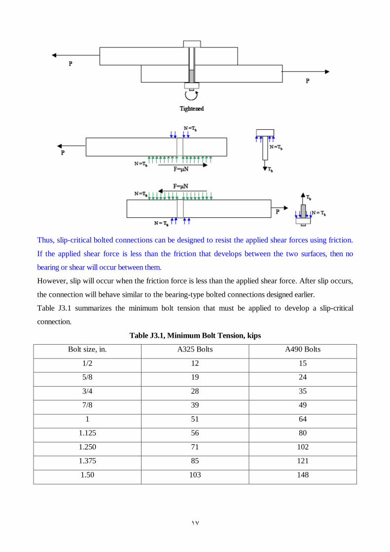
7.7 SLIP-CRITICAL BOLTED CONNECTIONS
In some structures, notably bridges, the load on connections can undergo many cyclesof reversals. In
such case, fatigue of the fasteners can become critical if the connection is allowed to slip with each
reversal, and a slip-critical connection is advisable.
High strength (A325 and A490) bolts can be installed with such a degree of tightness that they are
subject to large tensile forces.
These large tensile forces in the bolt clamp the connected plates together. The shear force applied to
such a tightened connection will be resisted by friction as shown in the Figure below.
If an external load P is applied, a friction force will develop between the connected parts.
The maximum possible value of this force is:
F = μ N
Where μ is the coefficient of static friction between the connected parts, and N is the normal
compressive force acting on the inner surfaces.
The value of μ will depend on the surface condition of the steel.
١٧
Thus, slip-critical bolted connections can be designed to resist the applied shear forces using friction.
If the applied shear force is less than the friction that develops between the two surfaces, then no
bearing or shear will occur between them.
However, slip will occur when the friction force is less than the applied shear force. After slip occurs,
the connection will behave similar to the bearing-type bolted connections designed earlier.
Table J3.1 summarizes the minimum bolt tension that must be applied to develop a slip-critical
connection.
Table J3.1, Minimum Bolt Tension, kips
Bolt size, in. A325 Bolts A490 Bolts
1/2 12 15
5/8 19 24
3/4 28 35
7/8 39 49
1 51 64
1.125 56 80
1.250 71 102
1.375 85 121
1.50 103 148

١٨
The shear resistance of fully tensioned bolts to slip at factored loads is given by AISC Specification
J3.8 a
Shear resistance at factored load = φRn = 1.13 µ Tb Ns
Where, φ = 1.0 for standard holes
µ = mean slip coefficient
µ = 0.33 for class A surface with unpainted clean mill scale surface)
µ = 0.50 for class (B) surface (blast clean surface).
Tb = minimum bolt tension given in Table J3.1
Ns = number of slip planes (shear planes)
Table 7-15 of the AISC manual gives the shear resistance of fully tensioned bolts to slip at factored
loads on class A surfaces.
For example, the shear resistance of 1.125 in. bolt fully tensioned to 56 kips (Table J3.1) is equal to 20.9
kips (Class A faying surface).
When the applied shear force exceeds the φRn value stated above, slip will occur in the connection.
The shear resistance of fully tensioned bolts to slip at service loads is given by AISC Specification
J3.8 b.
Shear resistance at service load = φRn = φ Fv Ab
Where, φ = 1.0 for standard holes
Fv = slip-critical resistance to shear at service loads, see Table A-J3.2 of the AISC manual
Table 7-16 of the AISC manual gives the shear resistance of fully tensioned bolts to slip at service loads
on class A surfaces.
For example, the shear resistance of 1.125 in. bolt fully tensioned to 56 kips is equal to 16.9 kips
When the applied shear force exceeds the φRn value stated above, slip will occur in the connection.
The final strength of the connection will depend on the shear strength of the bolts and on the bearing
strength of the bolts. This is the same strength as that of a bearing type connection.
Example 7.4
Design a slip-critical splice for a tension member subjected to 300 kips of tension loading. The
tension member is a W8 x 28 section made from A992 (50 ksi) material. The unfactored dead load is
equal to 50 kips and the unfactored live load is equal to 150 kips. Use A325 bolts. The splice should
be slip-critical at service loads.

١٩
Solution
Step I. Service and factored loads
• Service Load = D + L = 200 kips.
• Factored design load = 1.2 D + 1.6 L = 300 kips
• Tension member is W8 x 28 section made from A992 (50 ksi) steel. The tension splice must be slip
critical (i.e., it must not slip) at service loads.
Step II. Slip-critical splice connection • φRn of one fully-tensioned slip-critical bolt = φ Fv Ab
• If db = 3/4 in.
φRn of one bolt = 1.0 x 17 x π x 0.752/4 = 7.51 kips
Note, Fv = 17 ksi from Table A-J3.2
φRn of n bolts = 7.51 x n > 200 kips (splice must be slip-critical at service)
Therefore, n > 26.63
• If db = 7/8 in.
φRn of one bolt = 10.2 kips
φRn of n bolts = 10.2 x n > 200 kips (splice must be slip-critical at service)
Therefore, n > 19.6 bolts
Say we provide 24 bolts on either side of the center line, 6 on either side of the flanges, top + bottom
Note that there are 24 bolts on either side of the center line. In all there are 48 numbers - 7/8 in
dia bolts used in the connection.
٢٠
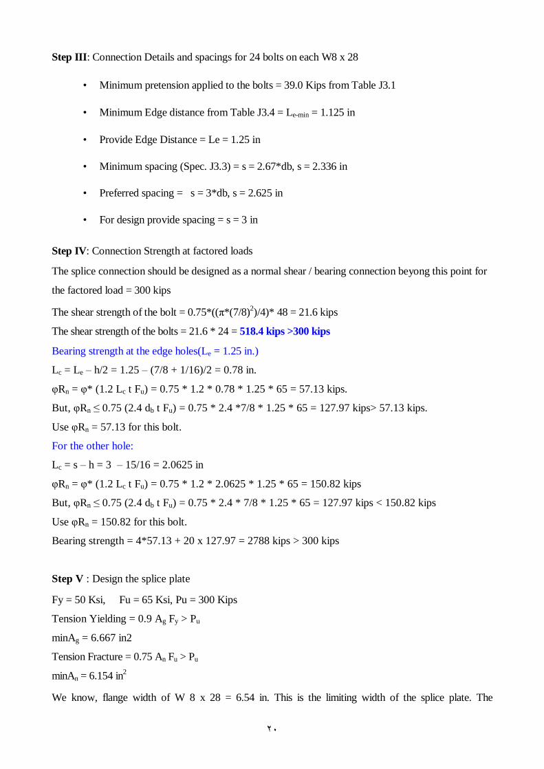
Step III: Connection Details and spacings for 24 bolts on each W8 x 28
• Minimum pretension applied to the bolts = 39.0 Kips from Table J3.1
• Minimum Edge distance from Table J3.4 = Le-min = 1.125 in
• Provide Edge Distance = Le = 1.25 in
• Minimum spacing (Spec. J3.3) = s = 2.67*db, s = 2.336 in
• Preferred spacing = s = 3*db, s = 2.625 in
• For design provide spacing = s = 3 in
Step IV: Connection Strength at factored loads
The splice connection should be designed as a normal shear / bearing connection beyong this point for
the factored load = 300 kips
The shear strength of the bolt = 0.75*((π*(7/8)2)/4)* 48 = 21.6 kips
The shear strength of the bolts = 21.6 * 24 = 518.4 kips >300 kips
Bearing strength at the edge holes(Le = 1.25 in.)
Lc = Le – h/2 = 1.25 – (7/8 + 1/16)/2 = 0.78 in.
φRn = φ* (1.2 Lc t Fu) = 0.75 * 1.2 * 0.78 * 1.25 * 65 = 57.13 kips.
But, φRn ≤ 0.75 (2.4 db t Fu) = 0.75 * 2.4 *7/8 * 1.25 * 65 = 127.97 kips> 57.13 kips.
Use φRn = 57.13 for this bolt.
For the other hole:
Lc = s – h = 3 – 15/16 = 2.0625 in
φRn = φ* (1.2 Lc t Fu) = 0.75 * 1.2 * 2.0625 * 1.25 * 65 = 150.82 kips
But, φRn ≤ 0.75 (2.4 db t Fu) = 0.75 * 2.4 * 7/8 * 1.25 * 65 = 127.97 kips < 150.82 kips
Use φRn = 150.82 for this bolt.
Bearing strength = 4*57.13 + 20 x 127.97 = 2788 kips > 300 kips
Step V : Design the splice plate
Fy = 50 Ksi, Fu = 65 Ksi, Pu = 300 Kips
Tension Yielding = 0.9 Ag Fy > Pu
minAg = 6.667 in2
Tension Fracture = 0.75 An Fu > Pu
minAn = 6.154 in2
We know, flange width of W 8 x 28 = 6.54 in. This is the limiting width of the splice plate. The

٢١
unknown quantity which is the thickness of each splice plate is calculated as shown.
Net area = Gross area - area of the bolts
An = Ag – 4 (7/8 + 1/8) t
Where Ag for the splice plate is 6.54 * t
6.154 = 6.54*t – 4*t = 2.54*t
So, tmin = 6.154/2.54 = 2.42 in (This is the total thickness of the plate at the top and bottom)
Assume each plate of the dimensions 6.54*1.25
Therefore, total plate thickness = 1.25 * 2 = 2.5 > 2.42
Check for An and Ag
Ag = 2.5 * 6.54 = 16.35 in2 > 6.667 in2
An = 16.35 – 4 * (7/8 +1/8) * 2.5 = 6.35 in2 > 6.154 in2
Max. An = 0.85 Ag = 0.85 * 16.35 = 13.898 > 6.35 OK
Strength of the splice plate in
Yielding = 0.9 * Ag* Fy = 735.75 Kips > 300 kips
Fracture = 0.75 * An* Fu = 309.563 Kips > 300 kips
Check for bearing strength of the splice plates
Since the splice plate has the same thickness of the flange and the same edge distance, so there isn't
any problem in the bearing strength of the splice plate.
Check for block shear rupture
Step VI: Check member yield, fracture and block shear..
Example 7.5
Modify Example 7.3 so that the connection system is slip critical for the factored load of 100 kips
Solution
Step I. Design and select a trial tension member
• See Table 3-7 of the AISC manual.
• Select 2L 3.5 x 2.5 x 1/4 with φPn = 130.5 kips (yielding) >100 kips
Step II. Select size and number of bolts (modified step)
• The connection must be designed to be slip-critical at the factored loads
φRn for one bolt = 1.0 x 1.13 x µ x Tb x Ns
φRn for one 3/4 in. bolt = 1.0 x 1.13 x 0.33 x 28 x 2 = 20.9 kips
φRn for one 7/8 in. bolt = 1.0 x 1.13 x 0.33 x 39 x 2 = 29.1 kips
We need at least five ¾ in. bolts to have strength φRn = 5 x 20.9 = 104.5 k > 100 k

٢٢
We need at least four 7/8 in. bolts to have strength φRn = 4 x 29.1 = 116.4 k> 100
Use five ¾ in. fully tightened bolts. Bolts must be tightened to 28 kips
Compare with solution for example 4.2 where only four snug-tight ¾ in bolts design.
For the remaining steps III to VII follow Example 7.3
Step III. Design edge distance and bolt spacing
Step IV. Check the bearing strength at bolt holes in angles
Step V. Check the fracture and block shear strength of the tension member
Step VI. Design the gusset plate
Step VII. Bearing strength at bolt holes in gusset plates
See examples 7.5, 7.6, 7.7 and 7.8
7.8 HIGH-STRENGTH BOLTS IN TENSION
The nominal tensile strength of a bolt (Rn) can be found as:
Where
Ft = Tensile strength of bolt material (120 ksi for A – 325 Bolts & 150 ksi for A – 490 Bolts).
An = Bolt net area through threaded zone*.
* Thread cross section area
Where, db = diameter of bolt (shank)
n = number of threads per inch.
This net area ≈ 0.75 to 0.79 of the bolt gross area Ab (area of the shank).
Thus:
ntn AFR =
( )btn AFR 75.0=
2974307850
−+=
ndb
..
( ) )75.0(75.075.0 btbtn AFAFR == φφ
٢٣
Where
φ = 0.75 as stipulated in AISC J3.6
Ab = Gross area of the bolt (Shank section).
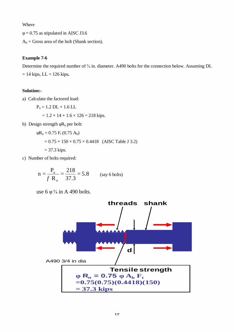
Example 7-6
Determine the required number of ¾ in. diameter. A490 bolts for the connection below. Assuming DL
= 14 kips, LL = 126 kips.
Solution:-
a) Calculate the factored load:
Pu = 1.2 DL + 1.6 LL
= 1.2 × 14 + 1.6 × 126 = 218 kips.
b) Design strength φRn per bolt:
φRn = 0.75 Ft (0.75 Ab)
= 0.75 × 150 × 0.75 × 0.4418 (AISC Table J 3.2)
= 37.3 kips.
c) Number of bolts required:
(say 6 bolts)
use 6 φ ¾ in A 490 bolts.
d
Tensile strengthφ Rn = 0.75 φ Ab Ft=0.75(0.75)(0.4418)(150) = 37.3 kips
threads shank
A490 3/4 in dia
5.837.3218
R Pn
n
u ===φ

٢٤
PRYING ACTION
In most connection in which fasteners are subjected to tension force, the flexiblity of the connected
parts can lead to deformation that increase the tension applied to the fasteners.
The additional tension is called a prying force.
If the connected parts are sufficiently rigid, this shifting of force willnot occure, and there will be no
prying action.
The maximum value of the prying force will be reached when only the corners of the flange remain in
contact with the other connected part. The following Figures explain this case:
The first sketch shows the bracket before loading by force P. The middle sketch shows how the part deflects in the absence of the mounting surface and the reaction at the bolt, F = P. The final sketch shows how the mounting surface restrains deflections by pushing against the part and introduces a secondary reaction from the prying action of magnitude Q. Bolt reactions are now amplified and
Bc = P + Q.

٢٥
In this type of connections, bending caused by the prying action will usually control the design of the
connected part.
Two limit states are possible:
• Tensile failure of the bolts.
• Bending failure of the tee.
The design of connection subjected to prying is essentially a trial and error process.
Table 9-2 provided in Part 9 of the Manual can be helpful in choosing a trial shape.
Once the trial shape has been selected and the number of bolts and their layout estimated, Equations
7.14 and 7.17 can be used to verify the choices.
For more information please read (319-325) pages from the text book.
For any qustions you can see me in the office hours.
7.9 COMBINED SHEAR AND TENSION IN FASTENERS
In most cases in which the bolt is subjected to both shear and tension, the connection is loaded
eccentrically.
However, in some simple connections the fasteners are in a state of comined loading.
As in the other cases of comined loading, an interaction formula approach can be used.
From a test results, an elliptical interaction curve was observed:
Where
Tu is the factored tensile load on the bolt
(ΦRn)t is the design strength of the bolt in tension
٢٦
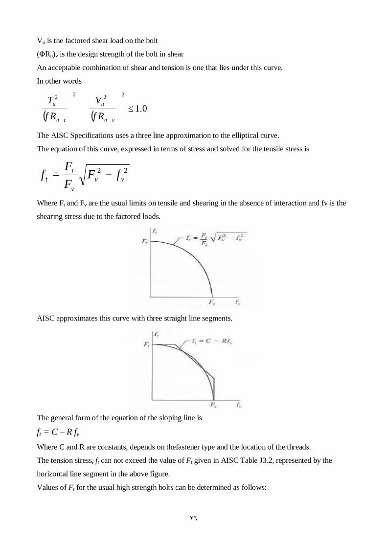
Vu is the factored shear load on the bolt
(ΦRn)v is the design strength of the bolt in shear
An acceptable combination of shear and tension is one that lies under this curve.
In other words
( ) ( ) 0.12222
≤
+
vn
u
tn
u
RV
RT
φφ
The AISC Specifications uses a three line approximation to the elliptical curve.
The equation of this curve, expressed in terms of stress and solved for the tensile stress is
22vv
v
tt fF
FF
f −=
Where Ft and Fv are the usual limits on tensile and shearing in the absence of interaction and fv is the
shearing stress due to the factored loads.
AISC approximates this curve with three straight line segments.
The general form of the equation of the sloping line is
ft = C – R fv Where C and R are constants, depends on thefastener type and the location of the threads.
The tension stress, ft can not exceed the value of Ft given in AISC Table J3.2, represented by the
horizontal line segment in the above figure.
Values of Ft for the usual high strength bolts can be determined as follows:

٢٧
A325 bolts:
Ft = 117 – 2.5 fv ≤ 90 when threads are in the shear plane.
Ft = 117 – 2.0 fv ≤ 90 when threads are not in the shear plane.
A490 bolts:
Ft = 147 – 2.5 fv ≤ 113 when threads are in the shear plane.
Ft = 147 – 2.0 fv ≤ 113 when threads are not in the shear plane.
The shearing strength Fv is the same as for the case of shear only.
In slip-critical connections, the effect of tensile force will reduce the clamping force
So reduction factore must be used to determine the slip-critical shear strength.
)13.1(1Re
bb
u
NTT
factorduction −=
Where
Tu is the total factored tensile load on the connection.
Tb is the prescribed iniial bolt tension (Table J3.1).
Nb is the number of bolts.
Example7.7
A WT10.5X31 is used as a bracket to transmit a 60 kips service load to a W 14X90 column as shown
in Figure. The load consists of 15 kips dead load and 45 kips live load. Four 7/8 inch diameter A325
bolts are used. The column is A992 steel, and the bracket is A36. Assume all spacing and edge
distance requirements are satisfied, including those necessary for the use of the maximum design
strength in bearing. Determine the adequacy of the bolts for the following types of connections:
• Bearing type connection with threads in shear plane.
• Slip-critical connection with threads in shear plane.
Solution
The factored load = 1.2 D + 1.6 L = 1.2*15 + 1.6*45 = 90 kips
A- Bearing connection:
The total shear force = 3/5 * 90 = 54 kips

٢٨
The shear force per bolt = 54/4 = 13.5 kips
The bolt area = (π*(7/8)2)/4 = 0.6013 in2
The shear strength per bolt is
(ΦRn)v = ΦFvAb = 0.75 * 48 * 0.6013 = 21.65 kips > 13.5 kips (OK)
The bearing strength is ( flange of tee controls)
ΦRn = Φ*2.4*dt*Fu = 0.75*2.4*7/8*58 = 56.18 kips > 13.5 kips
The tensile load = 4/5 * 90 = 72 kips
The tensile load per bolt = 72/4 = 18 kips
From AISC Table J3.5
Ft = 117 – 2.5 fv ≤ 90 ksi
fv = Fv/Ab =13.5 / 0.6013 = 22.45 ksi
Ft = 117 – 2.5 *22.45 = 60.88 ksi < 90 ksi (OK)
The tensile strength per bolt = ΦRn = ΦFtAb = 0.75 * 60.88 * 0.6013 = 27.5 kips > 18 kips (OK)
The connection is adequate as a bearing type connection.
Note
Prying action has not been included in the analysis
B Slip-critical connection
From previous the shear, bearing and tension strength are satisfactory.
The slip-critical design strengthis
Φrstr = 1.13 μTbNs
Φrstr = 1.13 * 0.33 * 39 * 1 * 4 = 58.17 kips
Since there is a tensile load on the bolts, so the slip-strength load must be reduced by a factor of
5916.0)4*39*13.1(
721Re =−=factorduction
The reduced strength = 0.5916 * 58.17 = 34.4 kips < 54 kips (N.S)
The connection is inadequate as a slip-critical connection.
Example7.8
A concentrically loaded connection is subjected to a service load shear force of 50 kips and aservice
loadtensile force of 100 kips. The load are 25% dead load and 75% live load. The fasteners will be in
single shear, and bearing strength will be controlled by a5/16 inch thick connected part of A36 steel.
Assume that all spacing and edge distances are satisfactory, including those that permit the maximum
bearing strength of Φ (2.4 dtFu) to be used. Determine the number of 3/4 inch diameter A325 bolts for
the following case:
• A bearing type connection with threads in the plane of the shear.
• A slip-critical connection with threads in the plane of the shear
٢٩
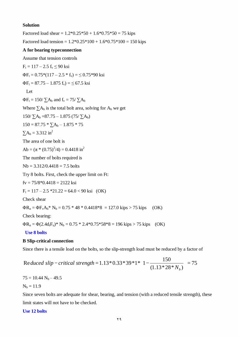
Solution
Factored load shear = 1.2*0.25*50 + 1.6*0.75*50 = 75 kips
Factored load tension = 1.2*0.25*100 + 1.6*0.75*100 = 150 kips
A for bearing typeconnection
Assume that tension controls
Ft = 117 – 2.5 fv ≤ 90 ksi
ΦFt = 0.75*(117 – 2.5 * fv) = ≤ 0.75*90 ksi
ΦFt = 87.75 – 1.875 fv) = ≤ 67.5 ksi
Let
ΦFt = 150/ ∑Ab and fv = 75/ ∑Ab
Where ∑Ab is the total bolt area, solving for Ab we get
150/ ∑Ab =87.75 – 1.875 (75/ ∑Ab)
150 = 87.75 * ∑Ab – 1.875 * 75
∑Ab = 3.312 in2
The area of one bolt is
Ab = (π * (0.75)2/4) = 0.4418 in2
The number of bolts required is
Nb = 3.312/0.4418 = 7.5 bolts
Try 8 bolts. First, check the upper limit on Ft:
fv = 75/8*0.4418 = 2122 ksi
Ft = 117 – 2.5 *21.22 = 64.0 < 90 ksi (OK)
Check shear
ΦRn = ΦFvAb* Nb = 0.75 * 48 * 0.4418*8 = 127.0 kips > 75 kips (OK)
Check bearing:
ΦRn = Φ(2.4dtFu)* Nb = 0.75 * 2.4*0.75*58*8 = 196 kips > 75 kips (OK)
Use 8 bolts
B Slip-critical connection
Since there is a tensile load on the bolts, so the slip-strength load must be reduced by a factor of
75)*28*13.1(
1501*1*39*33.0*13.1Re =
−=−
bNstrengthcriticalslipduced
75 = 10.44 Nb – 49.5
Nb = 11.9
Since seven bolts are adequate for shear, bearing, and tension (with a reduced tensile strength), these
limit states will not have to be checked.
Use 12 bolts
٣٠
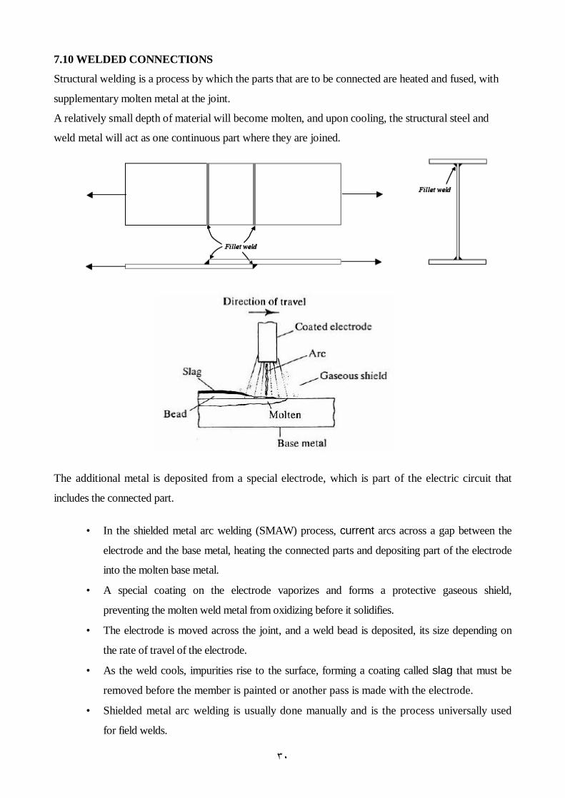
7.10 WELDED CONNECTIONS
Structural welding is a process by which the parts that are to be connected are heated and fused, with
supplementary molten metal at the joint.
A relatively small depth of material will become molten, and upon cooling, the structural steel and
weld metal will act as one continuous part where they are joined.
The additional metal is deposited from a special electrode, which is part of the electric circuit that
includes the connected part.
• In the shielded metal arc welding (SMAW) process, current arcs across a gap between the
electrode and the base metal, heating the connected parts and depositing part of the electrode
into the molten base metal.
• A special coating on the electrode vaporizes and forms a protective gaseous shield,
preventing the molten weld metal from oxidizing before it solidifies.
• The electrode is moved across the joint, and a weld bead is deposited, its size depending on
the rate of travel of the electrode.
• As the weld cools, impurities rise to the surface, forming a coating called slag that must be
removed before the member is painted or another pass is made with the electrode.
• Shielded metal arc welding is usually done manually and is the process universally used
for field welds.
٣١
For shop welding, an automatic or semi automatic process is usually used. Foremost among these is
the submerged arc welding (SAW).
In this process, the end of the electrode and the arc are submerged in a granular flux that melts and
forms a gaseous shield. There is more penetration into the base metal than with shielded metal arc
welding, and higher strength results.
Other commonly used processes for shop welding are gas shielded metal arc, flux cored arc, and
electro-slag welding.
Quality control of welded connections is particularly difficult, because defects below the surface, or
even minor flaws at the surface, will escape visual detection. Welders must be properly certified, and
for critical work, special inspection techniques such as radiography or ultrasonic testing must be used.
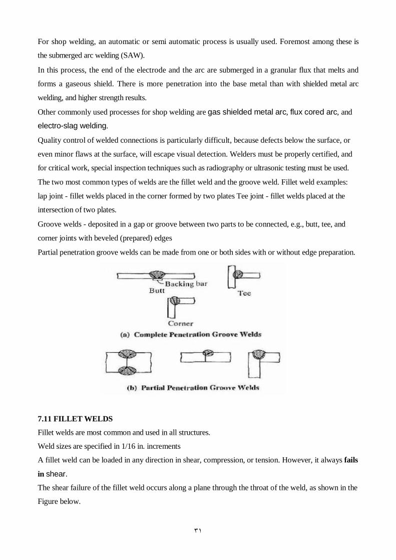
The two most common types of welds are the fillet weld and the groove weld. Fillet weld examples:
lap joint - fillet welds placed in the corner formed by two plates Tee joint - fillet welds placed at the
intersection of two plates.
Groove welds - deposited in a gap or groove between two parts to be connected, e.g., butt, tee, and
corner joints with beveled (prepared) edges
Partial penetration groove welds can be made from one or both sides with or without edge preparation.
7.11 FILLET WELDS
Fillet welds are most common and used in all structures.
Weld sizes are specified in 1/16 in. increments
A fillet weld can be loaded in any direction in shear, compression, or tension. However, it always fails
in shear.
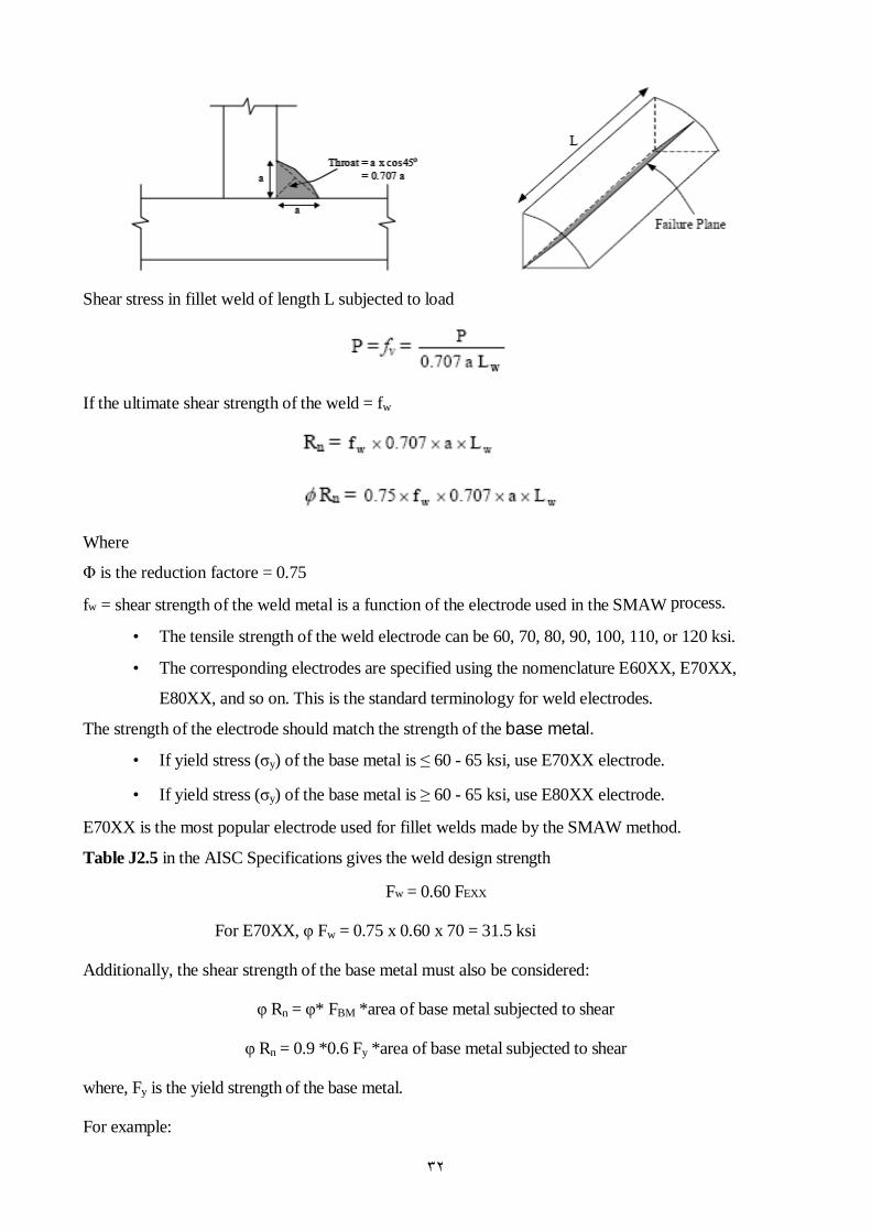
The shear failure of the fillet weld occurs along a plane through the throat of the weld, as shown in the
Figure below.
٣٢
Shear stress in fillet weld of length L subjected to load
If the ultimate shear strength of the weld = fw
Where
Φ is the reduction factore = 0.75
fw = shear strength of the weld metal is a function of the electrode used in the SMAW process.
• The tensile strength of the weld electrode can be 60, 70, 80, 90, 100, 110, or 120 ksi.
• The corresponding electrodes are specified using the nomenclature E60XX, E70XX,
E80XX, and so on. This is the standard terminology for weld electrodes.
The strength of the electrode should match the strength of the base metal.
• If yield stress (σy) of the base metal is ≤ 60 - 65 ksi, use E70XX electrode.
• If yield stress (σy) of the base metal is ≥ 60 - 65 ksi, use E80XX electrode.
E70XX is the most popular electrode used for fillet welds made by the SMAW method.
Table J2.5 in the AISC Specifications gives the weld design strength
Fw = 0.60 FEXX
For E70XX, φ Fw = 0.75 x 0.60 x 70 = 31.5 ksi
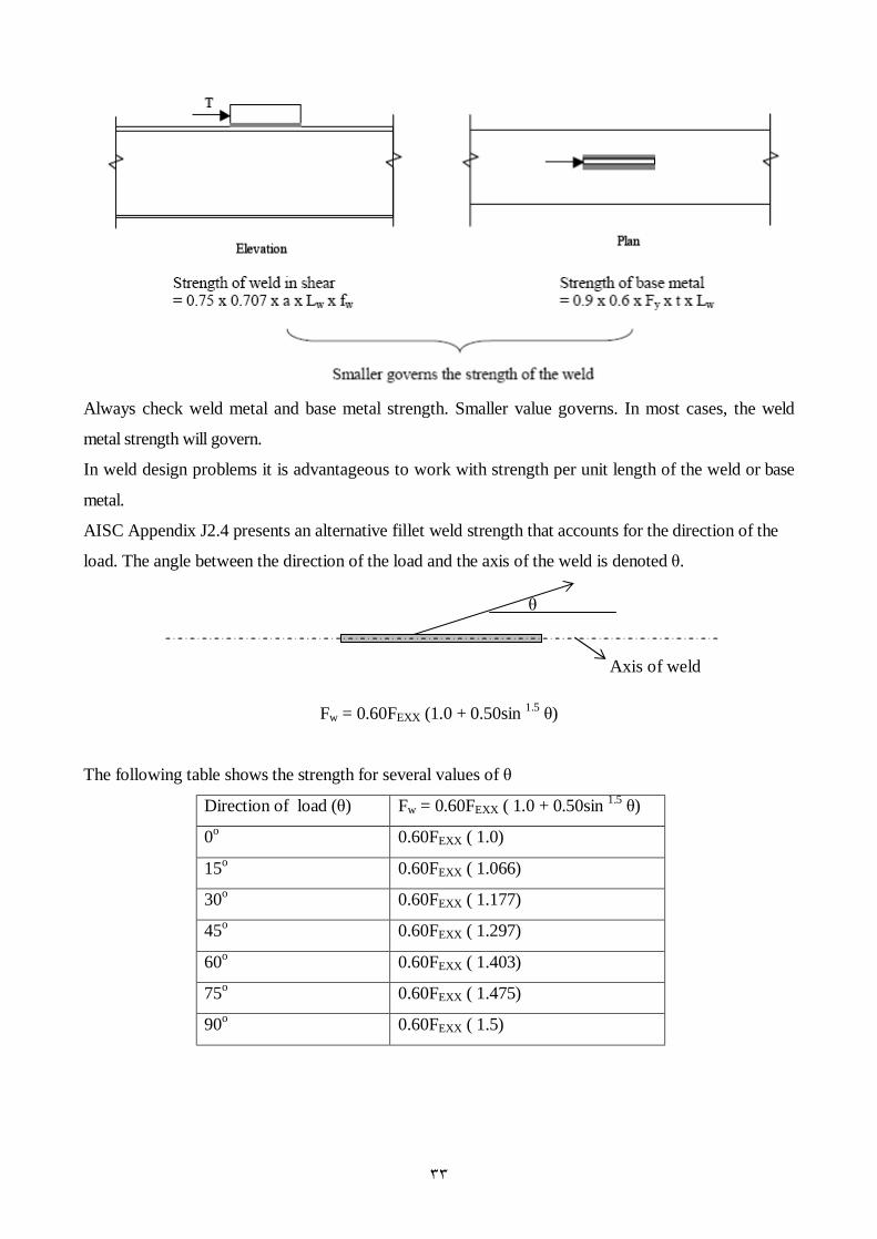
Additionally, the shear strength of the base metal must also be considered:
φ Rn = φ* FBM *area of base metal subjected to shear
φ Rn = 0.9 *0.6 Fy *area of base metal subjected to shear
where, Fy is the yield strength of the base metal.
For example:
٣٣
Always check weld metal and base metal strength. Smaller value governs. In most cases, the weld
metal strength will govern.
In weld design problems it is advantageous to work with strength per unit length of the weld or base
metal.
AISC Appendix J2.4 presents an alternative fillet weld strength that accounts for the direction of the
load. The angle between the direction of the load and the axis of the weld is denoted θ.
Fw = 0.60FEXX (1.0 + 0.50sin 1.5 θ)
The following table shows the strength for several values of θ
Direction of load (θ) Fw = 0.60FEXX ( 1.0 + 0.50sin 1.5 θ)
0o 0.60FEXX ( 1.0)
15o 0.60FEXX ( 1.066)
30o 0.60FEXX ( 1.177)
45o 0.60FEXX ( 1.297)
60o 0.60FEXX ( 1.403)
75o 0.60FEXX ( 1.475)
90o 0.60FEXX ( 1.5)
θ
Axis of weld

٣٤
Limitations on weld dimensions (See AISC Spec. J2.2b of manual)
Minimum size (amin)
Function of the thickness of the thickest connected plate and is given in Table J2.4 of the AISC spec.
Maximum size (amax)
Function of the thickness of the thinnest connected plate:
• For plates with thickness ≤ 0.25 in., amax = 0.25 in.
• For plates with thickness ≥ 0.25 in., amax = t - 1/16 in.
Minimum length (Lw)
• length (Lw) ≥ 4 a otherwise, aeff = Lw / 4
• Read J2.2 b
• Intermittent fillet welds: Lw-min = 4 a and 1.5 in.
Maximum effective length - read AISC J2.2b
• If weld length Lw < 100 a, then effective weld length (Lw-eff) = Lw
• If Lw < 100 a, then effective weld length (Lw-eff) = Lw (1.2 - 0.002 Lw/a) ≤ Lw
• If Lw > 300 a, the effective weld length (Lw-eff) = 0.6 Lw
Weld Terminations - read AISC J2.2b
• Lap joint - fillet welds terminate at a distance > a from edge.
• Weld returns around corners must be > 2 a
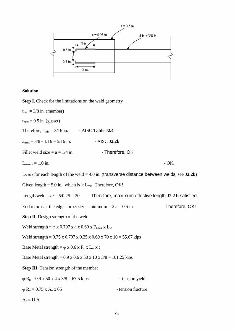
Example 7.9
Determine the design strength of the tension member and connection system shown below. The
tension member is a 4 in. x 3/8 in. thick rectangular bar. It is welded to a 1/2 in. thick gusset plate using
E70XX electrode. Consider the yielding and fracture of the tension member. Consider the shear strength
of the weld metal and the surrounding base metal.
٣٥
Solution
Step I. Check for the limitations on the weld geometry
tmin = 3/8 in. (member)
tmax = 0.5 in. (gusset)
Therefore, amin = 3/16 in. - AISC Table J2.4
amax = 3/8 - 1/16 = 5/16 in. - AISC J2.2b
Fillet weld size = a = 1/4 in. - Therefore, OK!
Lw-min = 1.0 in. - OK.
Lw-min for each length of the weld = 4.0 in. (transverse distance between welds, see J2.2b)
Given length = 5.0 in., which is > Lmin. Therefore, OK!
Length/weld size = 5/0.25 = 20 - Therefore, maximum effective length J2.2 b satisfied.
End returns at the edge corner size - minimum = 2 a = 0.5 in. -Therefore, OK!
Step II. Design strength of the weld
Weld strength = φ x 0.707 x a x 0.60 x FEXX x Lw
Weld strength = 0.75 x 0.707 x 0.25 x 0.60 x 70 x 10 = 55.67 kips
Base Metal strength = φ x 0.6 x Fy x Lw x t
Base Metal strength = 0.9 x 0.6 x 50 x 10 x 3/8 = 101.25 kips
Step III. Tension strength of the member
φ Rn = 0.9 x 50 x 4 x 3/8 = 67.5 kips - tension yield
φ Rn = 0.75 x Ae x 65 - tension fracture
Ae = U A
٣٦
A = Ag = 4 x 3/8 = 1.5 in2
U = 0.75 , since connection length (Lconn) < 1.5 w - See Spec. B3
Therefore, φ Rn = 54.8 kips
The design strength of the member-connection system = 54.8 kips. Tension fracture of
the member governs. The end returns at the corners were not included in the
calculations.
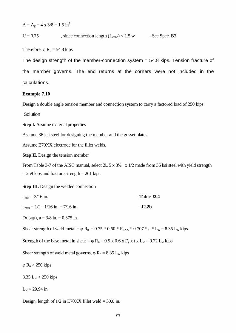
Example 7.10
Design a double angle tension member and connection system to carry a factored load of 250 kips.
Solution
Step I. Assume material properties
Assume 36 ksi steel for designing the member and the gusset plates.
Assume E70XX electrode for the fillet welds.
Step II. Design the tension member
From Table 3-7 of the AISC manual, select 2L 5 x 3½ x 1/2 made from 36 ksi steel with yield strength
= 259 kips and fracture strength = 261 kips.
Step III. Design the welded connection
amin = 3/16 in. - Table J2.4
amax = 1/2 - 1/16 in. = 7/16 in. - J2.2b
Design, a = 3/8 in. = 0.375 in.
Shear strength of weld metal = φ Rn = 0.75 * 0.60 * FEXX * 0.707 * a * Lw = 8.35 Lw kips
Strength of the base metal in shear = φ Rn = 0.9 x 0.6 x Fy x t x Lw = 9.72 Lw kips
Shear strength of weld metal governs, φ Rn = 8.35 Lw kips
φ Rn > 250 kips
8.35 Lw > 250 kips
Lw > 29.94 in.
Design, length of 1/2 in E70XX fillet weld = 30.0 in.
٣٧
Shear strength of fillet weld = 250.5 kips
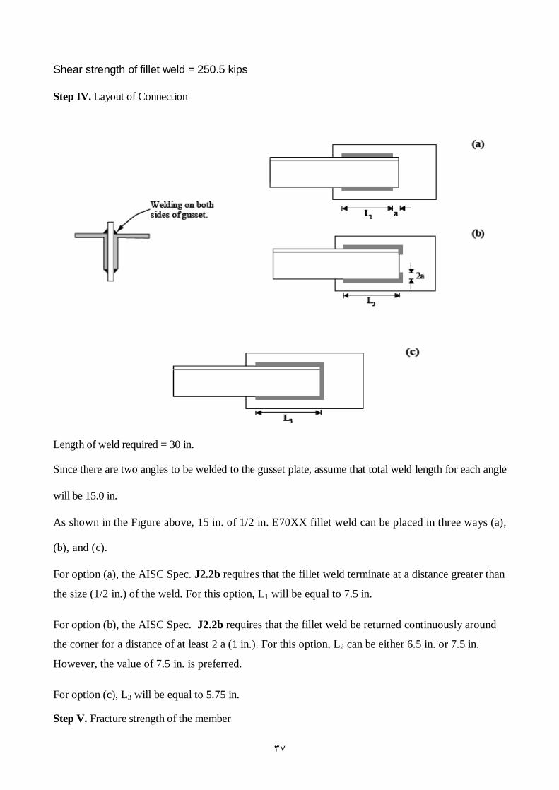
Step IV. Layout of Connection
Length of weld required = 30 in.
Since there are two angles to be welded to the gusset plate, assume that total weld length for each angle
will be 15.0 in.
As shown in the Figure above, 15 in. of 1/2 in. E70XX fillet weld can be placed in three ways (a),
(b), and (c).
For option (a), the AISC Spec. J2.2b requires that the fillet weld terminate at a distance greater than
the size (1/2 in.) of the weld. For this option, L1 will be equal to 7.5 in.
For option (b), the AISC Spec. J2.2b requires that the fillet weld be returned continuously around
the corner for a distance of at least 2 a (1 in.). For this option, L2 can be either 6.5 in. or 7.5 in.
However, the value of 7.5 in. is preferred.
For option (c), L3 will be equal to 5.75 in.
Step V. Fracture strength of the member

٣٨
Ae = U Ag
For the double angle section, use the value of x from Table 1-7 on page 1-37 of manual.
Assume case (a). Therefore, U =0.88
φ Rn = 0.75 x 0.88 x 8.00 x 58 = 306.24 kips > 250 kips - fracture limit state is ok
Step VI. Design the gusset plate
φ Rn > Tu tension yielding limit state
Therefore, 0.9 * Ag * 36 > 250 kips
Ag > 7.71 in2
φ Rn > Tu tension fracture limit state
Therefore, 0.75 * An * Fu > 250 kips
An ≤ 0.85 Ag
An > 5.747 in2
Therefore, Ag > 6.76 in2
Design gusset plate thickness = 1.0 in. a nd width = 8.0 in.
)ومن أحسن قوال ممن دعا الى اهللا وعمل صالحا وقال انني من المسلمین(