Embed Size (px)
Citation preview

7.1
Chapter 7: Bending and Shear in Simple Beams
Introduction
A beam is a long, slender structural member that resists loads that are generally
applied transverse (perpendicular) to its longitudinal axis.
• These transverse loads cause the beam to bend in the plane of the applied
loads.
• Internal bending stresses and shear stresses are developed in the material as it
resists these loads.
• Axial forces (and axial stresses) may also be present in the beam when the
applied loads are not perpendicular to the axis.
Beams are a common type of structural member.
• Beams are used in the roofs and floors of buildings.
• Beams are used for bridges and other structural applications.
Beams are usually long, straight, prismatic (i.e. symmetrical) bars.
• Not all beams need to be horizontal; they may be vertical or on a slant.
Designing a beam consists essentially in selecting the cross section that will
provide the most effective resistance to shear and bending produced by the
applied loads.
7.1 Classification of Beams and Loads
Beams are often classified according to their support conditions. Following are six
major beam types. The span “L” is the distance between supports.
Statically
Determinate
Simply supported Overhanging Cantilever
7.2
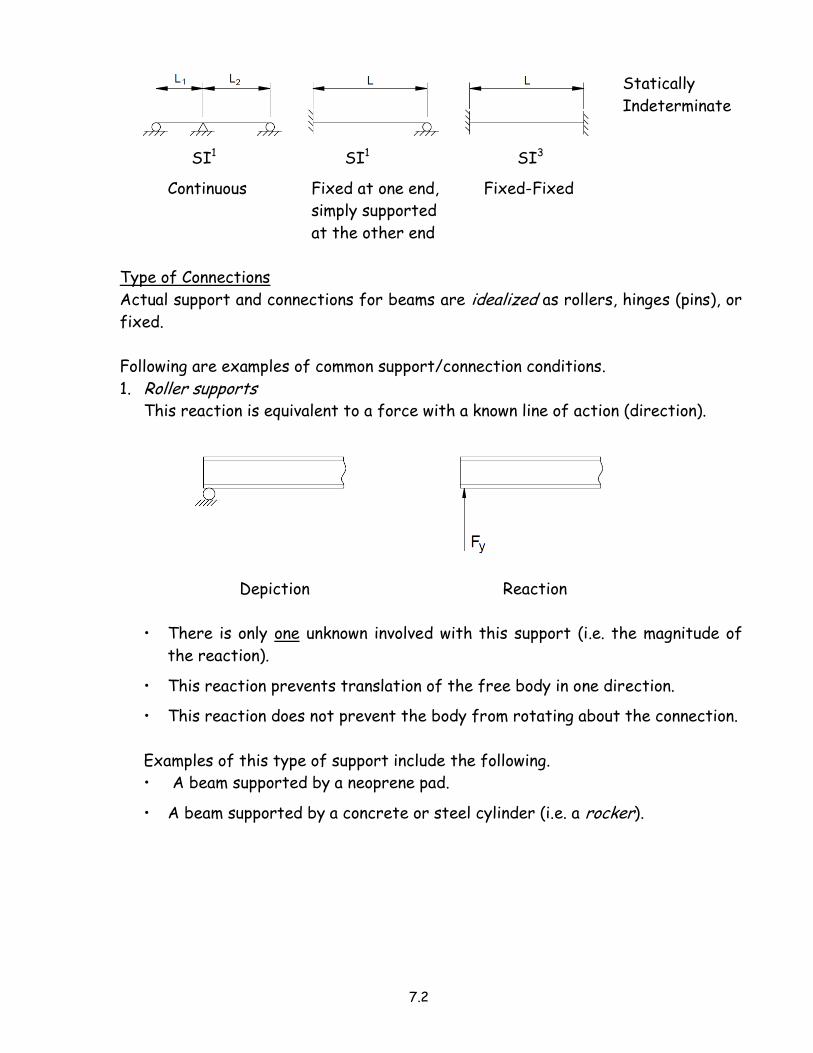
Statically
Indeterminate
SI1 SI1 SI3
Continuous Fixed at one end, Fixed-Fixed
simply supported
at the other end
Type of Connections
Actual support and connections for beams are idealized as rollers, hinges (pins), or
fixed.
Following are examples of common support/connection conditions.
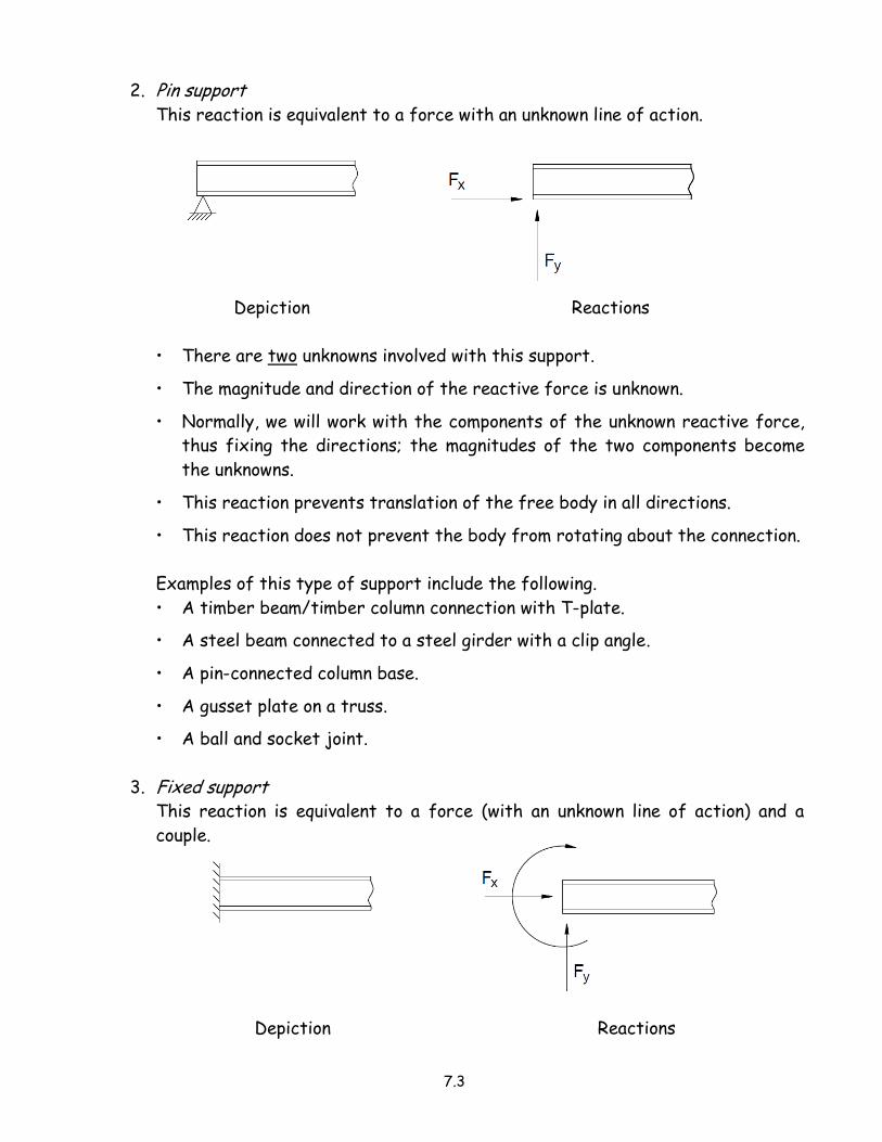
1. Roller supports
This reaction is equivalent to a force with a known line of action (direction).
Depiction Reaction
• There is only one unknown involved with this support (i.e. the magnitude of
the reaction).
• This reaction prevents translation of the free body in one direction.
• This reaction does not prevent the body from rotating about the connection.
Examples of this type of support include the following.
• A beam supported by a neoprene pad.
• A beam supported by a concrete or steel cylinder (i.e. a rocker).
7.3
2. Pin support
This reaction is equivalent to a force with an unknown line of action.
Depiction Reactions
• There are two unknowns involved with this support.
• The magnitude and direction of the reactive force is unknown.
• Normally, we will work with the components of the unknown reactive force,
thus fixing the directions; the magnitudes of the two components become
the unknowns.
• This reaction prevents translation of the free body in all directions.
• This reaction does not prevent the body from rotating about the connection.
Examples of this type of support include the following.
• A timber beam/timber column connection with T-plate.
• A steel beam connected to a steel girder with a clip angle.
• A pin-connected column base.
• A gusset plate on a truss.
• A ball and socket joint.
3. Fixed support
This reaction is equivalent to a force (with an unknown line of action) and a
couple.
Depiction Reactions

7.4
• Reactions of this group involve three unknowns, consisting of the two
components of the force and the moment of the couple.
• This reaction is caused by “fixed supports” which oppose any motion of the
free body and thus constrain it completely, preventing both translation and
rotation.
Examples of this type of support include
• A reinforced concrete floor/wall connection.
• A steel strap welded to a gusset plate.
• A timber pole embedded in a concrete base.
• A beam/column moment connection.
When the sense (direction) of an unknown force or couple is not known, no attempt
should be made to determine the correct direction.
• The sense of the force or couple should be arbitrarily assumed.
• The sign of the answer that is obtained will indicate whether the assumption is
correct or not.
Types of Loads
There are four fundamental types of loads that can act on a beam.
• Concentrated load (ex. beam-to-girder
loads, column loads)
• Uniformly distributed load (ex. joists to
beam, built-up roof, snow load, dead load,
live load)
• Non-uniformly distributed load (ex. soil
or water pressure behind a retaining wall)
7.5
• Pure moment (ex. starting torque on
machinery)
7.2 Shear and Bending Moment
When a beam is subjected to applied loads, the beam must resist these loads to
remain in equilibrium.
• To resist the applied loads, an internal force system is developed within the
beam.
• Stresses and deflections in beams are the result of these internal forces (axial
forces, shear forces, and moments).
It is convenient to “map” these internal actions (forces and moments).
• Diagrams are drawn to provide a complete picture of the magnitudes and
directions of the forces and moments that act along the length of the beam.
• These diagrams are referred to as load (P), shear (V), and moment (M)
diagrams.
Shear and moment diagrams can be drawn in three ways.
• By calculating values of shear and moment at various sections along the beam
and plotting enough points to obtain a smooth curve. This procedure is time-
consuming.
• By writing equations for the values of shear and moment.
• By drawing the diagrams directly, understanding the relationship between load,
shear force and moment.
The two latter methods will be developed in the following sections of this chapter.
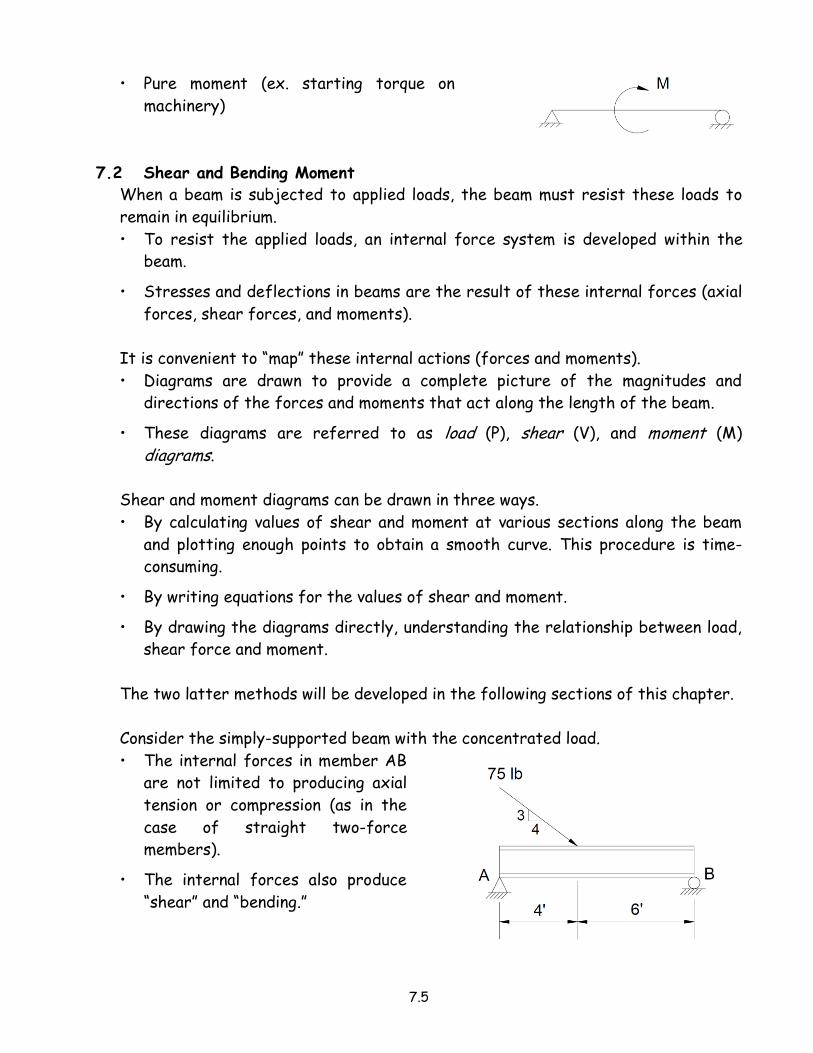
Consider the simply-supported beam with the concentrated load.
• The internal forces in member AB
are not limited to producing axial
tension or compression (as in the
case of straight two-force
members).
• The internal forces also produce
“shear” and “bending.”
7.6
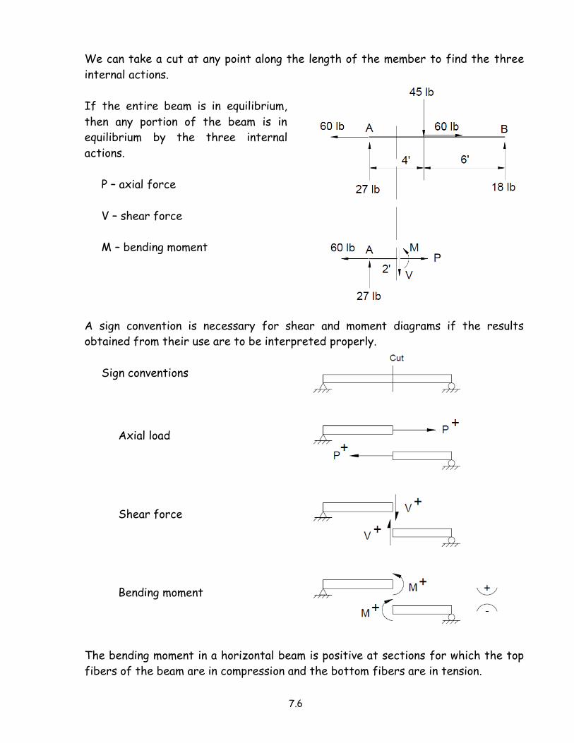
We can take a cut at any point along the length of the member to find the three
internal actions.
If the entire beam is in equilibrium,
then any portion of the beam is in
equilibrium by the three internal
actions.
P – axial force
V – shear force
M – bending moment
A sign convention is necessary for shear and moment diagrams if the results
obtained from their use are to be interpreted properly.
Sign conventions
Axial load
Shear force
Bending moment
The bending moment in a horizontal beam is positive at sections for which the top
fibers of the beam are in compression and the bottom fibers are in tension.

7.7
It is important to note that the sign convention used for shear and moment
diagrams is different from the conventions used in writing the equations of
equilibrium.
• When using the equations of equilibrium, forces directed up or to the right are
positive; counterclockwise moments are positive and clockwise moments are
negative.
• The new sign conventions are used only for showing the directions of the
internal actions on free-body diagrams and for plotting the shear and moment
diagrams.
7.8
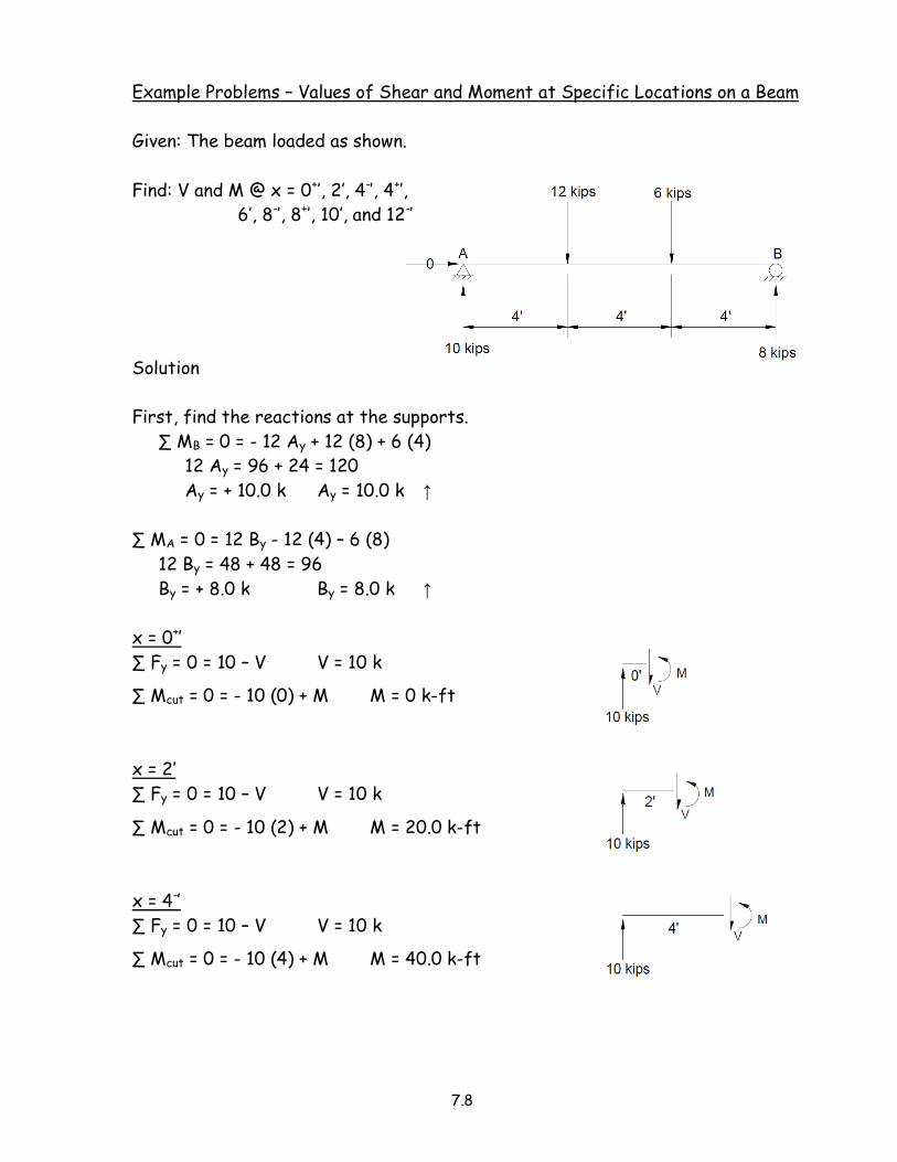
Example Problems – Values of Shear and Moment at Specific Locations on a Beam
Given: The beam loaded as shown.
Find: V and M @ x = 0+’, 2’, 4-’, 4+’,
6’, 8-’, 8+’, 10’, and 12-’
Solution
First, find the reactions at the supports.
∑ MB = 0 = - 12 Ay + 12 (8) + 6 (4)
12 Ay = 96 + 24 = 120
Ay = + 10.0 k Ay = 10.0 k ↑
∑ MA = 0 = 12 By - 12 (4) – 6 (8)
12 By = 48 + 48 = 96
By = + 8.0 k By = 8.0 k ↑
x = 0+’
∑ Fy = 0 = 10 – V V = 10 k
∑ Mcut = 0 = - 10 (0) + M M = 0 k-ft
x = 2’
∑ Fy = 0 = 10 – V V = 10 k
∑ Mcut = 0 = - 10 (2) + M M = 20.0 k-ft
x = 4-’
∑ Fy = 0 = 10 – V V = 10 k
∑ Mcut = 0 = - 10 (4) + M M = 40.0 k-ft

7.9
x = 4+’
∑ Fy = 0 = 10 – 12 - V V = - 2 k
∑ Mcut = 0 = - 10 (4) + 12 (0) + M
M = 40.0 k-ft
x = 6’
∑ Fy = 0 = 10 – 12 - V V = - 2 k
∑ Mcut = 0 = - 10 (6) + 12 (2) + M
M = 60 – 24 = 36.0 k-ft
x = 8-’
∑ Fy = 0 = 10 – 12 - V V = - 2 k
∑ Mcut = 0 = - 10 (8) + 12 (4) + M
M = 80 – 48 = 32.0 k-ft
x = 8+’
∑ Fy = 0 = 10 – 12 – 6 - V
V = - 8 k
∑ Mcut = 0 = - 10 (8) + 12 (4)
+ 6 (0) + M
M = 80 – 48 – 0 = 32.0 k-ft
x = 10’
∑ Fy = 0 = 10 – 12 – 6 - V
V = - 8 k
∑ Mcut = 0 = - 10 (10) + 12 (6)
+ 6 (2) + M
M = 100 – 72 – 12 = 16.0 k-ft
x = 12-’
∑ Fy = 0 = 10 – 12 – 6 - V
V = - 8 k
∑ Mcut = 0 = - 10 (12) + 12 (8)
+ 6 (4) + M
M = 120 – 96 – 24 = 0 k-ft

7.10
To simplify the calculations, use a free body diagram from the right side.
x = 10’
∑ Fy = 0 = V + 8 V = - 8 k
∑ Mcut = 0 = - M + 8 (2) M = 16.0 k-ft
x = 12-’
∑ Fy = 0 = V + 8 V = - 8 k
∑ Mcut = 0 = - M + 8 (0) M = 0 k-ft
Note: The moment is zero at the supports of simply supported beams.

7.11
Example
Given: The beam loaded as shown.
Find: V and M @ x = 0+’, 3’, 6-’, 6+’,
7.5’, and 9-’
Solution
First, find the reactions at the supports.
∑ MB = 0 = - 9 Ay + ½ (6) 6 [3 + (2/3) 6]
+ ½ (3) 6 [3 + (1/3) 6]
9 Ay = 18 (7) + 9 (5) = 126 + 45 = 171
Ay = + 19.0 Ay = 19.0 k ↑
∑ MA = 0 = 9 By – ½ (6) 6 (1/3) 6 – ½ (3) 6 (2/3) 6
9 By = 18 (2) + 9 (4) = 36 + 36 = 72
By = + 8.0 By = 8.0 k ↑
x = 0+’
∑ Fy = 0 = 19 – V V = 19 k
∑ Mcut = 0 = - 19 (0) + M M = 0 k-ft
x = 3’
∑ Fy = 0 = 19 – ½ (6) 3 – ½ (4.5) 3 – V
V = 19 – 9 – 6.75 = 3.25 k
∑ Mcut = 0 = - 19 (3) + ½ (6) 3 (2/3) 3
+ ½ (4.5) 3 (1/3) 3 + M
M = 57 – 18 – 6.75 = 32.25 k-ft
x = 6-’
∑ Fy = 0 = 19 – ½ (6) 6 - ½ (3) 6 – V
V = 19 – 18 – 9 = - 8.0 k
∑ Mcut = 0 = - 19 (6) + ½ (6) 6 (2/3) 6
+ ½ (3) 6 (1/3) 6 + M
M = 114 – 72 – 18 = 24.0 k-ft

7.12
x = 6+’
∑ Fy = 0 = V + 8 V = - 8.0 k
∑ Mcut = 0 = - M + 8 (3) M = 24.0 k-ft
x = 7.5’
∑ Fy = 0 = V + 8 V = - 8.0 k
∑ Mcut = 0 = - M + 8 (1.5) M = 12.0 k-ft
x = 9-’
∑ Fy = 0 = V + 8 V = - 8.0 k
∑ Mcut = 0 = - M + 8 (0) M = 0 k-ft

7.13
7.3 Equilibrium Method for Shear and Moment Diagrams
One basic method used in constructing shear (V) and moment (M) diagrams is
referred to as the equilibrium method.
• Specific values of V and M are determined from the equations of equilibrium.
Procedure
Determine how many sets of equations are needed to define shear and moment
across the length of the beam.
• If the load is uniformly distributed or varies according to a known equation
along the entire beam, a single equation can be written for shear (V) or moment
(M).
• Generally, it is necessary to divide the beam into intervals bounded by abrupt
changes in the loading (e.g. the end or beginning of a distributed load, a
concentrated load or couple).
A free-body diagram is drawn representing the section of the beam of interest.
• An origin is usually selected at the left end of the beam for reference.
Equations for V and M are determined from free-body diagrams of portions of the
beam.
7.14
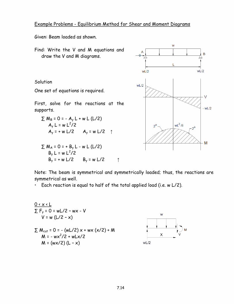
Example Problems - Equilibrium Method for Shear and Moment Diagrams
Given: Beam loaded as shown.
Find: Write the V and M equations and
draw the V and M diagrams.
Solution
One set of equations is required.
First, solve for the reactions at the
supports.
∑ MB = 0 = - Ay L + w L (L/2)
Ay L = w L2/2
Ay = + w L/2 Ay = w L/2 ↑
∑ MA = 0 = + By L - w L (L/2)
By L = w L2/2
By = + w L/2 By = w L/2 ↑
Note: The beam is symmetrical and symmetrically loaded; thus, the reactions are
symmetrical as well.
• Each reaction is equal to half of the total applied load (i.e. w L/2).
0 < x < L
∑ Fy = 0 = wL/2 – wx - V
V = w (L/2 – x)
∑ Mcut = 0 = - (wL/2) x + wx (x/2) + M
M = - wx2/2 + wLx/2
M = (wx/2) (L – x)

7.15
Example
Given: Beam loaded as shown.
Find: Write the V and M equations and
draw the V and M diagrams.
Solution
Two sets of equations are required.
First, solve for the reactions at the
supports.
∑ MB = 0 = - Ay L + P (L/2)
Ay = P/2
∑ MA = 0 = By L - P (L/2)
By = P/2
Note: The beam is symmetrical and symmetrically loaded; thus, the reactions are
symmetrical as well.
• Each reaction is equal to half of the total applied load (i.e. P/2).
0 < x < L/2
∑ Fy = 0 = P/2 – V
V = P/2
∑ Mcut = 0 = - (P/2) x + M
M = Px/2
L/2 < x < L
∑ Fy = 0 = P/2 – P - V
V = - P/2
∑ Mcut = 0 = - (P/2) x + P (x – L/2) + M
M = Px/2 – Px + PL/2
M = P/2 (L – x)

7.16
Problem 7.8 (p. 360)
Given: Beam loaded as shown.
Find: Write the V and M equations and
draw the V and M diagrams.
Solution
Two sets of equations required.
First, solve for the reactions at the
supports.
∑ MB = 0 = - 6 Ay + ½ (240) 3 [3 + (1/3) 3]
+ ½ (240) 3 (2/3) 3
6 Ay = 360 (4) + 360 (2)
6 Ay = 1440 + 720 = 2160
Ay = + 360 k Ay = 360 k ↑
∑ MA = 0 = + 6 By + ½ (240) 3 [(2/3) 3]
+ ½ (240) (3) [3 + (1/3) 3]
6 By = 360 (2) + 360 (4) = 720 + 1440 = 2160
By = + 360 k By = 360 k ↑
Note: The beam is symmetrical and symmetrically loaded; thus, the reactions are
symmetrical as well.
• Each reaction is equal to half of the total applied load.
- Total load = ½ x 240 x 6 = 720 kips
- Each reaction = ½ x 720 = 360 kips
0’ < x < 3’
Since the intensity of the distributed load varies,
an equation is needed to define the intensity of
the distributed load (p) as a function of position
“x” along the beam.

7.17
Using the general equation of a line: p = m x + c
• Determine the slope m.
m = (240 – 0)/3 = 80
So, p = 80 x + c
• Next, determine the “y-intercept” value “c”.
Known points on the line include: when x = 0, p = 0 and when x = 3, p = 240.
Substituting the second condition into the equation p = 80 x + c:
240 = 80 (3) + c c = 240 – 240 = 0
Thus, p = 80 x + 0, and p = 80 x
Now write the equations for shear and moment.
∑ Fy = 0 = 360 – V – ½ p x
0 = 360 – V – ½ (80x) x
V = 360 – 40x2
∑ Mcut = 0 = - 360x + M + ½ p x (x/3)
0 = -360x + M + ½ (80x) x (x/3)
M = +360x – 40/3 x3
M = 360x – 13.33 x3
3’ < x < 6’
Since the intensity of the distributed load varies,
an equation is needed to define the intensity of
the distributed load (p) as a function of position
“x” along the beam.
Using the general equation of a line: p = m x + c
• Determine the slope m.
m = (0 - 240)/3 = - 80
So, p = - 80 x + c
• Next, determine the “y-intercept” value “c”.
Known points on the line include: when x = 3, p = 240 and when x = 6, p = 0.
Substituting the first condition into the equation p = 80 x + c:
240 = - 80 (3) + c c = 240 + 240 = 480
Thus, p = - 80 x + 480, and p = 480 – 80 x

7.18
Now write the equations for shear and moment.
∑ Fy = 0 = 360 + V – ½ p (6 - x)
0 = 360 + V – ½ (480 – 80 x) (6 - x)
V = - 360 + (240 – 40 x) (6 - x)
V = - 360 + 1440 – 240 x – 240 x + 40 x2
V = 40 x2 – 480 x + 1080
∑ Mcut = 0 = 360 (6 - x) – M - ½ p (6 - x) (1/3) (6 - x)
0 = 360 (6 - x) – M - ½ (480 – 80 x) (6 - x) (1/3) (6 - x)
M = 360 (6 - x) – (1/6) (480 – 80 x) (6 - x) (6 - x)
M = 360 (6 - x) – (1/6) (480 – 80 x) (36 – 12 x + x2)
M = 2160 – 360 x – (1/6) (17,280 – 8640 x + 1440 x2 – 80 x3)
M = 2160 – 360 x – 2880 + 1440 x – 240 x2 + (80/6) x3
M = 13.33 x3 – 240 x2 + 1080 x - 720

7.19
7.4 Relationship Between Load, Transverse Shear, and Bending Moment
The methods presented previously for drawing shear and bending moment diagrams
become increasingly cumbersome as the loading becomes more complex.
The construction of shear and bending moment diagrams can be simplified by
understanding the relationships that exist between the load, shear force, and
bending moment.
Relationships between Load and Shear Force
∑Fy = 0 = V – (V + ∆V) – w ∆x, where w = w(x) and is constant for small ∆x.
∆V = – w ∆x
∆V/∆x = - w
In calculus, as ∆x → 0, the above expression takes the following form.
dV / dx = - w
The equation shows that the slope of the shear diagram is equal to the intensity of
the loading at that point, times minus one.
If we integrate this expression between two points
dV = - w dx
∫ dV = - ∫w dx
V1 – V2 = - ∫w(x) dx
The equation shows that the change in shear between two points is equal to the
area under the load diagram, times minus one.
These equations are not valid under a concentrated load.
• The shear diagram makes a jump at the point of a concentrated load.

7.20
Relationships between Shear Force and Bending Moment
From the free body diagram,
∑ MR = 0 = - M – V ∆x + w (∆x)2/2 + M + ∆M
∆M = V ∆x – ½ w (∆x)2
∆M = V ∆x
∆M / ∆x = V
In calculus, as ∆x → 0, the above expression takes the following form.
dM/dx = V
The equation shows that the value of the slope on the bending moment diagram is
equal to the height of the shear diagram at that point.
• When the shear force is zero, the slope on the bending moment diagram is zero.
• Zero slope on the moment diagram corresponds to a point of a maximum bending
moment (either the absolute maximum or a local maximum).
If we integrate this expression between two points
dM = V dx
∫ dM = ∫ V dx
M1 – M2 = ∫ V(x) dx
The equation shows that the change in bending moment between two points is equal
to the area under the shear diagram.
These equations are not valid under a concentrated couple.
• The bending moment diagram makes a jump at the point of a concentrated
couple.
7.21
7.5 Semigraphical Method for Load, Shear and Moment Diagrams
The method presented in the previous section is referred to as the semigraphical method.
• These expressions can be used to draw the shear and moment diagrams.
• These expressions can be used to compute values of shear and moment at
various points along the beam.
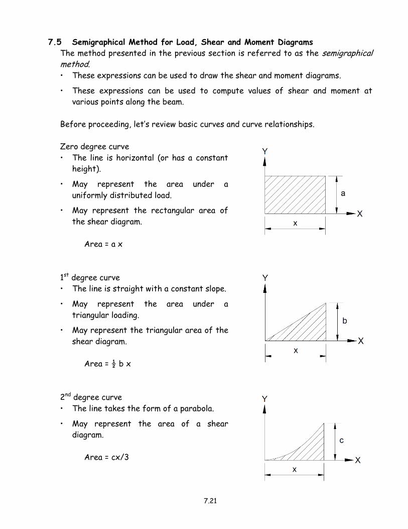
Before proceeding, let’s review basic curves and curve relationships.
Zero degree curve
• The line is horizontal (or has a constant
height).
• May represent the area under a
uniformly distributed load.
• May represent the rectangular area of
the shear diagram.
Area = a x
1st degree curve
• The line is straight with a constant slope.
• May represent the area under a
triangular loading.
• May represent the triangular area of the
shear diagram.
Area = ½ b x
2nd degree curve
• The line takes the form of a parabola.
• May represent the area of a shear
diagram.
Area = cx/3

7.22
General considerations for drawing V and M diagrams.
• For a simply supported beam, the shear at the ends must equal the end
reactions.
• For a simply supported beam, the moment at the ends must be zero.
• Shear and moment are both zero at the free end of a beam.
• For a fixed support, the reactions at the support are equal to the shear and
moment values at the support.
• A concentrated load produces a “jump” in the shear diagram of the same
magnitude and direction as the concentrated load.
• A concentrated couple produces a “jump” in the moment diagram of the same
magnitude as the concentrated couple. The direction of the “jump” should be
determined by analysis.
• At points where shear is zero, moment is a maximum.

7.23
Example Problems - Shear and Moment Diagrams by the Semigraphical Method
Given: The beam loaded as shown.
Find: Draw the shear and moment
diagrams.
For the shear diagram
0 < x < L
Area under the load diagram = + w L
∆V = - Area = - w L
At the right end of the beam
V2 = V1 + ∆V
= w L/2 – w L = - wL/2
For the moment diagram
0 < x < L/2
Area under the shear diagram = + ½ (½ w L) (L/2) = w L2/8
∆M = Area = + w L2/8
At mid-span
M2 = M1 + ∆M
= 0 + w L2/8 = w L2/8
Note: At x = L/2, V = 0, and dM/dx = 0 (there is a horizontal tangent on the
moment diagram).
7.24
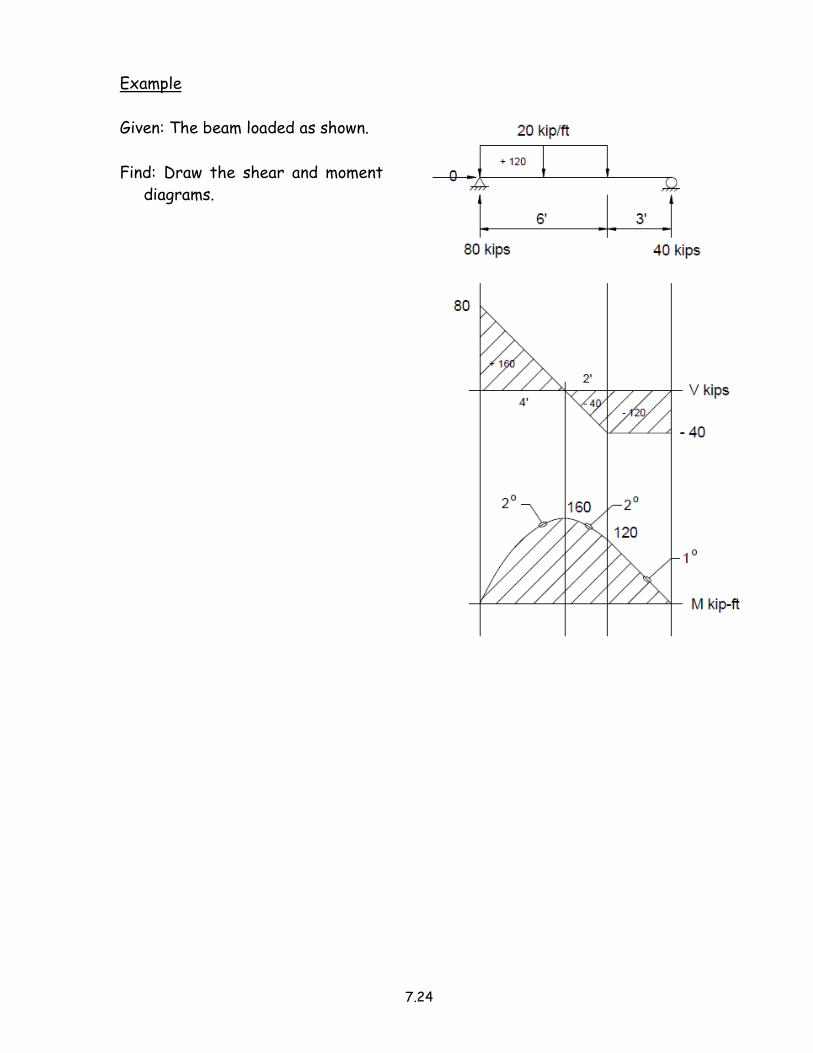
Example
Given: The beam loaded as shown.
Find: Draw the shear and moment
diagrams.

7.25
Example
Given: The beam loaded as shown.
Find: Draw the shear and moment
diagrams.

7.26
Example
Given: The beam loaded as shown.
Find: Draw the shear and moment
diagrams.
Find the reactions at the supports.
∑ MD = 0 = - 18 Ay + ½ (4) 12 [6 + (1/3) 12]
+ 20 (3) – 120
18 Ay = 24 (10) + 20 (3) – 120
18 Ay = 240 + 60 – 120 = 180
Ay = + 10.0 k Ay = 10 k ↑
∑ MA = 0 = - ½ (4) 12 (8)
– 20 (15) – 120 + 18 Dy
18 Dy = 192 + 300 + 120 = 612
Dy = + 34.0 k Dy = 34.0 k ↑
In order to draw the first part of the moment diagram, the location for the point
of maximum moment (i.e. V = 0 kips) needs to be determined so that the area under
the shear diagram may be calculated.
• Write an equation for shear between x = 0’ and x = 12’.
∑ Fy = 0 = 10 – ½ (x) (x/3) – V
V = 10 – x2/6
Let V = 0, thus 0 = 10 – x2/6
x2 = 60.0
x = 7.75’
• The change in moment from x = 0’ to x = 7.75’ is equal to the area under the
shear diagram.
Δ M = (2/3) 10 (7.75’) = 51.7 kip-ft

7.27
• Determine the value of moment at x = 12’ and plot this value on the moment
diagram.
- The area under the portion shear diagram between x = 7.75’ and x = 12’
cannot be calculated using standard formulas since there is no horizontal
tangent at x = 7.75’ or at x = 12’.
- Take a cut at x = 12’, draw the free
body diagram, and write the
equilibrium equation to determine the
value of moment.
- Then plot this value on the moment
diagram.
∑ Mcut = 0 = MB – 10 (12) + ½ (12) 4 (1/3)(12)
MB = 120 – 96 = 24.0 kip-ft
The concentrated couple at point C causes the moment diagram to jump up by 120
kip-ft (from – 18 kip-ft to + 102 kip-ft).
• Since the applied moment is acting clockwise, the internal resisting moment
increases, thus the jump “up” on the moment diagram.

7.28
Problem 7.8 (p. 360)
Note: This problem was previously
worked by writing the equations for
shear and moment.
Given: Beam loaded as shown.
Find: Draw the shear and moment
diagrams.
7.29
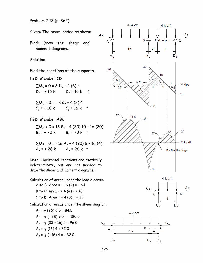
Problem 7.13 (p. 362)
Given: The beam loaded as shown.
Find: Draw the shear and
moment diagrams.
Solution
Find the reactions at the supports.
FBD: Member CD
∑MC = 0 = 8 Dy – 4 (8) 4
Dy = + 16 k Dy = 16 k ↑
∑MD = 0 = - 8 Cy + 4 (8) 4
Cy = + 16 k Cy = 16 k ↑
FBD: Member ABC
∑MA = 0 = 16 By – 4 (20) 10 – 16 (20)
By = + 70 k By = 70 k ↑
∑MB = 0 = - 16 Ay + 4 (20) 6 – 16 (4)
Ay = + 26 k Ay = 26 k ↑
Note: Horizontal reactions are statically
indeterminate, but are not needed to
draw the shear and moment diagrams.
Calculation of areas under the load diagram
A to B: Area = + 16 (4) = + 64
B to C: Area = + 4 (4) = + 16
C to D: Area = + 4 (8) = + 32
Calculation of areas under the shear diagram.
A1 = ½ (26) 6.5 = 84.5
A2 = ½ (- 38) 9.5 = - 180.5
A3 = ½ (32 + 16) 4 = 96.0
A4 = ½ (16) 4 = 32.0
A5 = ½ (- 16) 4 = - 32.0


![[9] shear force n bending moment](https://img.dokumen.tips/doc/110x75/553af101550346f92f8b4613/9-shear-force-n-bending-moment.jpg)