Embed Size (px)
DESCRIPTION
ENEE244 answer Key.
Citation preview

- 7.1 -
Chapter 7Problem Solutions
7.1. Excitation and output expressions:
J1 = xQ-2 + y
K1 = yQ-2 + x
-Q2J2 = x
-y-
K2 = xy + Q1z = Q1Q
-2 + x
-Q-1
Excitation table:
Present state(Q1Q2)
Excitation(J1K1,J2K2)
Output(z)
Inputs (xy) Inputs (xy)
00 01 10 11 00 01 10 11
00 00,10 11,00 10,00 11,01 1 1 0 0
01 01,10 11,00 00,00 10,01 1 1 0 0
10 00,11 11,01 10,01 11,01 1 1 1 1
11 01,11 11,01 00,01 10,01 0 0 0 0
Transition table:
Present state(Q1Q2)
Next state(Q+1Q
+2)
Output(z)
Inputs (xy) Inputs (xy)
00 01 10 11 00 01 10 11
00 01 10 10 10 1 1 0 0
01 01 11 01 10 1 1 0 0
10 11 00 10 00 1 1 1 1
11 00 00 10 10 0 0 0 0

- 7.2 -
7.1. (continued)
State table:
Present state Next state Output(z)
Inputs (xy) Inputs (xy)
00 01 10 11 00 01 10 11
00 A B C C C 1 1 0 0
01 B B D B C 1 1 0 0
10 C D A C A 1 1 1 1
11 D A A C C 0 0 0 0
State diagram:

- 7.3 -
7.2. Excitation and output expressions:
D1 = x-Q2
D2 = x-Q-1Q2 + xQ
-1Q-2
z = Q1Q2
Excitation table:
Present state(Q1Q2)
Excitation(D1D2)
Output(z)
Input (x)
0 1
00 00 01 0
01 11 00 0
10 00 00 0
11 10 00 1
Transition table (Same as excitation table):
Present state(Q1Q2)
Next state(Q+1Q
+2)
Output(z)
Input (x)
0 1
00 00 01 0
01 11 00 0
10 00 00 0
11 10 00 1
- 7.4 -
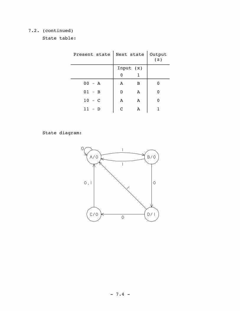
7.2. (continued)
State table:
Present state Next state Output(z)
Input (x)
0 1
00 A A B 0
01 B D A 0
10 C A A 0
11 D C A 1
State diagram:

- 7.5 -
7.3. Excitation and output expressions:
T1 = xQ2 + Q-1Q2
T2 = x + Q-1Q2
z1 = xQ-1
z2 = x-Q2
Excitation table:
Present state(Q1Q2)
Excitation(T1T2)
Output(z1z2)
Input (x) Input (x)
0 1 0 1
00 00 01 00 10
01 11 11 01 10
10 00 01 00 00
11 00 11 01 00
Transition table:
Present state(Q1Q2)
Next state(Q+1Q
+2)
Output(z1z2)
Input (x) Input (x)
0 1 0 1
00 00 01 00 10
01 10 10 01 10
10 10 11 00 00
11 11 00 01 00

- 7.6 -
7.3. (continued)
State table:
Present state Next state Output(z1z2)
Input (x) Input (x)
0 1 0 1
00 A A B 00 10
01 B C C 01 10
10 C C D 00 00
11 D D A 01 00
State diagram:

- 7.7 -
7.4. Excitation and output expressions:
J1 = Q2K1 = x
D2 = x(Q-1+Q
-2)
z = Q2 + x-Q1
Excitation table:
Present state(Q1Q2)
Excitation(J1K1,D2)
Output(z)
Input (x) Input (x)
0 1 0 1
00 00,0 01,1 0 0
01 10,0 11,1 1 1
10 00,0 01,1 1 0
11 10,0 11,0 1 1
Transition table:
Present state(Q1Q2)
Next state(Q+1Q
+2)
Output(z)
Input (x) Input (x)
0 1 0 1
00 00 01 0 0
01 10 11 1 1
10 10 01 1 0
11 10 00 1 1

- 7.8 -
7.4. (continued)
State table:
Present state Next state Output(z)
Input (x) Input (x)
0 1 0 1
00 A A B 0 0
01 B C D 1 1
10 C C B 1 0
11 D C A 1 1
State diagram:

- 7.9 -
7.5.
A: A multiple of three 1's have occurred (where none is a
multiple of three).
B: One greater than a multiple of three 1's have occurred.
C: Two 1's greater than a multiple of three 1's have
occurred.
Present state Next state Output(z)
Input (x) Input (x)
0 1 0 1
* A A B 0 0
B B C 0 0
C C A 0 1
7.6.
A: Last input was 0.
B: One 1 has occurred.
C: Two consecutive 1's have occurred.
D: Three consecutive 1's have occurred.
E: More than three consecutive 1's have occurred.
Present state Next state Output(z)
Input (x) Input (x)
0 1 0 1
* A A B 0 0
B A C 1 0
C A D 0 0
D A E 1 0
E A E 0 0

- 7.10 -
7.7.
A: Waiting for a single 0 (or, equivalently, 1's occurring
after more than one 0 has occurred).
B: Exactly one 0 has occurred.
C: Two or more consecutive 0's have occurred.
D: 1's occurring after exactly one 0.
Present state Next state Output(z)
Input (x) Input (x)
0 1 0 1
* A B A 0 0
B C D 0 1
C C A 0 0
D B D 0 1

- 7.11 -
7.8.
State definitionPresentstate
Next state Output(z)
Numberof inputs
Numberof 1's
Numberof 0's
Input (x) Input (x)
0 1 0 1
0 0 0 * A B C 0 0
1 0 1 B D E 0 0
1 1 0 C E F 0 0
2 0 2 D G H 0 0
2 1 1 E H I 0 0
2 2 0 F I J 0 0
3 0 3 G M K 0 0
3 1 2 H K L 0 0
3 2 1 I L M 0 0
3 3 0 J M M 0 0
4 1 3 K A A 1 0
4 2 2 L A A 0 1
Invalid code group M A A 1 1

- 7.12 -
7.9.
Presentstate
Next state Output(z)
State definitionInput (x) Input (x)
0 1 0 1
Awaiting 1st input ofsequence
* A B C 0 1
1st bit applied, retainapplied input
B D E 0 1
1st bit applied, complementapplied input
C E E 1 0
2nd bit applied, retainapplied input
D F G 0 1
2nd bit applied, complementapplied input
E G G 1 0
3rd bit applied, retainapplied input
F A A 0 1
3rd bit applied, complementapplied input
G A A 1 0

- 7.13 -
7.10. (a)
Presentstate
Next state Output(z)
State definitionInput (x) Input (x)
0 1 0 1
Awaiting 1st bit ofsequence (b4=g4)
* A B C 0 1
b4 bit was 0 (b3=g3) B D E 0 1
b4 bit was 1 (b3=g-3) C E D 1 0
b3 bit was 0 (b2=g2) D F G 0 1
b3 bit was 1 (b2=g-2) E G F 1 0
b2 bit was 0 (b1=g1) F H I 0 1
b2 bit was 1 (b1=g-1) G I H 1 0
b1 bit was 0 (b0=g0) H A A 0 1
b1 bit was 1 (b0=g-0) I A A 1 0

- 7.14 -
7.10. (continued)
(b) In problem 3.34 it was established that the algorithm
to convert an n-bit binary number bn-1bn-2...b1b0 into
its equivalent n-bit Gray code gn-1gn-2...g1g0 is
gn-1 = bn-1 gk-1 = bk bk-1 for n-1k1
Presentstate
Next state Output(z)
State definitionInput (x) Input (x)
0 1 0 1
Awaiting 1st bit ofsequence (g4=b4)
* A B C 0 1
g4 bit was 0 (g3=b4 b3) B D E 0 1
g4 bit was 1 (g3=b4 b3) C D E 1 0
g3 bit was 0 (g2=b3 b2) D F G 0 1
g3 bit was 1 (g2=b3 b2) E F G 1 0
g2 bit was 0 (g1=b2 b1) F H I 0 1
g2 bit was 1 (g1=b2 b1) G H I 1 0
g1 bit was 0 (g0=b1 b0) H A A 0 1
g1 bit was 1 (g0=b1 b0) I A A 1 0

- 7.15 -
7.11.
State definitionPresentstate
Next state Output(QAQBQC)
QA QB QCInput (x)
0 1
0 0 0 * A A B 000
1 0 0 B C D 100
0 1 0 C E F 010
1 1 0 D G H 110
0 0 1 E A B 001
1 0 1 F C D 101
0 1 1 G E F 011
1 1 1 H G H 111
7.12.
A: Even number of 1's have occurred, current output should
be 0.
B: Odd number of 1's have occurred, current output should
be 0.
C: Even number of 1's have occurred, current output should
be 1.
D: Odd number of 1's have occurred, current output should
be 1.
Present state Next state Output(z)
Input (x) Input (x)
0 1 0 1
* A A B 0 0
B B C 0 0
C C D 1 1
D D A 1 1

- 7.16 -
7.13. A possible initial state set is:
A: In a sequence of an even number of 0's.
B: In a sequence of an odd number of 0's.
C: In a sequence of 1's having a parity disagreeing with
the previous sequence of 0's.
D: In a sequence of 1's having a parity agreeing with the
previous sequence of 0's.
Present state Next state Output(z)
Input (x) Input (x)
0 1 0 1
* A B C 0 0
B A D 0 0
C B D 1 0
D B C 0 0
It is immediately noted that AD. The minimal state table
is:
Present state Next state Output(z)
Input (x) Input (x)
0 1 0 1
(A,D): * 1 2 3 0 0
(B): 2 1 1 0 0
(C): 3 2 1 1 0

- 7.17 -
7.14.
A: Waiting for the first 1 in a sequence of 1's.
B: One 1 has occurred.
C: Two 1's have occurred.
D: Three or more 1's have occurred.
Present state Next state Output(z)
Input (x) Input (x)
0 1 0 1
* A A B 0 0
B A C 0 0
C A D 0 0
D A D 0 1
7.15. Let the present state denote the previous three inputs,
i.e., xt-3, xt-2, and xt-1 where xt-i is the input at time
i.
State definitionPresentstate
Next state Output(z)
xt-3 xt-2 xt-1Input (x) Input (x)
0 1 0 1
0 0 0 * A A B 0 0
0 0 1 B C D 1 0
0 1 0 C E F 1 1
0 1 1 D G H 0 0
1 0 0 E A B 1 0
1 0 1 F C D 0 0
1 1 0 G E F 0 0
1 1 1 H G H 1 0

- 7.18 -
7.16. Using the same approach as the previous problem, the state
table is:
State definitionPresentstate
Next state Output(z)
xt-3 xt-2 xt-1Input (x) Input (x)
0 1 0 1
0 0 0 * A A B 0 1
0 0 1 B C D 0 0
0 1 0 C E F 0 0
0 1 1 D G H 1 0
1 0 0 E A B 0 1
1 0 1 F C D 0 0
1 1 0 G E F 0 0
1 1 1 H G H 1 0
For this table, however, AE, BF, CG, and DH. The
minimal state table is:
Present state Next state Output(z)
Input (x) Input (x)
0 1 0 1
(A,E): * 1 1 2 0 1
(B,F): 2 3 4 0 0
(C,G): 3 1 2 0 0
(D,H): 4 3 4 1 0

- 7.19 -
7.17. (a)
Equivalence classes of states:
{(A,E,H), (B,F), (C,G,I), (D)}
Minimal state table:
Present state Next state Output(z)
Input (x) Input (x)
0 1 0 1
(A,E,H): * 1 2 3 1 1
(B,F): 2 4 2 0 0
(C,G,I): 3 2 1 0 1
(D): 4 4 1 0 0

- 7.20 -
7.17. (continued)
(b)
Equivalence classes of states:
{(A,C,E), (B,G), (D), (F), (H)}
Minimal state table:
Present state Next state Output(z)
Input (x) Input (x)
0 1 0 1
(A,C,E): * 1 2 1 0 0
(B,G): 2 1 3 1 0
(D): 3 4 1 0 0
(F): 4 4 5 1 0
(H): 5 3 4 1 1

- 7.21 -
7.18.
Equivalence classes of states:
{(A,E,F), (B,G), (C,H), (D)}
Minimal state table:
Present state Next state Output(z)
Input (x)
0 1
(A,E,F): * 1 2 3 1
(B,G): 2 4 1 0
(C,H): 3 1 1 1
(D): 4 1 3 0

- 7.22 -
7.19. Transition table:
Present state(Q1Q2)
Next state(Q+1Q
+2)
Output(z)
Input (x) Input (x)
0 1 0 1
A 00 01 10 0 0
B 01 00 00 0 1
C 10 11 00 0 1
D 11 00 11 0 1
(a) The excitation table is the same as the transition
table where Di=Q+i.

- 7.23 -
7.19. (continued)
(b) Excitation table:
Present state(Q1Q2)
Excitation(J1K1,J2K2)
Output(z)
Input (x) Input (x)
0 1 0 1
00 0-,1- 1-,0- 0 0
01 0-,-1 0-,-1 0 1
10 -0,1- -1,0- 0 1
11 -1,-1 -0,-0 0 1
The output map and expression are the same as part (a).

- 7.24 -
7.19. (continued)
(c) Excitation table:
Present state(Q1Q2)
Excitation(T1T2)
Output(z)
Input (x) Input (x)
0 1 0 1
00 01 10 0 0
01 01 01 0 1
10 01 10 0 1
11 11 00 0 1
The output map and expression are the same as part (a).

- 7.25 -
7.19. (continued)
(d) Excitation table:
Present state(Q1Q2)
Excitation(S1R1,S2R2)
Output(z)
Input (x) Input (x)
0 1 0 1
00 0-,10 10,0- 0 0
01 0-,01 0-,01 0 1
10 -0,10 01,0- 0 1
11 01,01 -0,-0 0 1
The output map and expression are the same as part (a).

- 7.26 -
7.20. Adjacency conditions to be satisfied:
Rule I: (B,D), (B,C)
Rule II: (B,C), (A,D)(2×)
Rule III: (B,C,D)
State assignment map:
Transition table:
Present state(Q1Q2)
Next state(Q+1Q
+2)
Output(z)
Input (x) Input (x)
0 1 0 1
A 00 11 10 0 0
B 11 00 00 0 1
C 10 01 00 0 1
D 01 00 01 0 1

- 7.27 -
7.20. (continued)
(a) The excitation table is the same as the transition
table where Di=Q+i.

- 7.28 -
7.20. (continued)
(b) Excitation table:
Present state(Q1Q2)
Excitation(J1K1,J2K2)
Output(z)
Input (x) Input (x)
0 1 0 1
00 1-,1- 1-,0- 0 0
11 -1,-1 -1,-1 0 1
10 -1,1- -1,0- 0 1
01 0-,-1 0-,-0 0 1
The output map and expression are the same as part (a).

- 7.29 -
7.20. (continued)
(c) Excitation table:
Present state(Q1Q2)
Excitation(T1T2)
Output(z)
Input (x) Input (x)
0 1 0 1
00 11 10 0 0
11 11 11 0 1
10 11 10 0 1
01 01 00 0 1
The output map and expression are the same as part (a).

- 7.30 -
7.20. (continued)
(d) Excitation table:
Present state(Q1Q2)
Excitation(S1R1,S2R2)
Output(z)
Input (x) Input (x)
0 1 0 1
00 10,10 10,0- 0 0
11 01,01 01,01 0 1
10 01,10 01,0- 0 1
01 0-,01 0-,-0 0 1
The output map and expression are the same as part (a).

- 7.31 -
7.21. Transition table:
Present state(Q1Q2)
Next state(Q+1Q
+2)
Output(z)
Input (x)
0 1
A 00 00 01 1
B 01 10 00 0
C 10 00 11 0
D 11 10 10 1
(a) The excitation table is the same as the transition
table where Di=Q+i.

- 7.32 -
7.21. (continued)
(b) Excitation table:
Present state(Q1Q2)
Excitation(J1K1,J2K2)
Output(z)
Input (x)
0 1
00 0-,0- 0-,1- 1
01 1-,-1 0-,-1 0
10 -1,0- -0,1- 0
11 -0,-1 -0,-1 1
The output map and expression are the same as part (a).

- 7.33 -
7.21. (continued)
(c) Excitation table:
Present state(Q1Q2)
Excitation(T1T2)
Output(z)
Input (x)
0 1
00 00 01 1
01 11 01 0
10 10 01 0
11 01 01 1
The output map and expression are the same as part (a).

- 7.34 -
7.21. (continued)
(d) Excitation table:
Present state(Q1Q2)
Excitation(S1R1,S2R2)
Output(z)
Input (x)
0 1
00 0-,0- 0-,10 1
01 10,01 0-,01 0
10 01,0- -0,10 0
11 -0,01 -0,01 1
The output map and expression are the same as part (a).

- 7.35 -
7.22. Transition table:
Present State(Q1Q2Q3)
Next State(Q+1Q
+2Q
+3)
Output(z)
Input (x) Input (x)
0 1 0 1
A 000 001 000 0 0
B 001 000 010 1 0
C 010 011 000 0 0
D 011 011 100 1 0
E 100 010 011 1 1
(a) The excitation table is the same as the transition
table where Di=Q+i.

- 7.36 -
7.22. (continued)
(b) Excitation table:
Present state(Q1Q2Q3)
Excitation(J1K1,J2K2,J3K3)
Output(z)
Input (x) Input (x)
0 1 0 1
000 0-,0-,1- 0-,0-,0- 0 0
001 0-,0-,-1 0-,1-,-1 1 0
010 0-,-0,1- 0-,-1,0- 0 0
011 0-,-0,-0 1-,-1,-1 1 0
100 -1,1-,0- -1,1-,1- 1 1

- 7.37 -
7.22. (continued)

- 7.38 -
7.22. (continued)
The output map and expression are the same as part (a).
(c) Excitation table:
Present State(Q1Q2Q3)
Excitation(T1T2T3)
Output(z)
Input (x) Input (x)
0 1 0 1
000 001 000 0 0
001 001 011 1 0
010 001 010 0 0
011 000 111 1 0
100 110 111 1 1

- 7.39 -
7.22. (continued)
The output map and expression are the same as part (a).

- 7.40 -
7.22. (continued)
(d) Excitation table:
Present state(Q1Q2Q3)
Excitation(S1R1,S2R2,S3R3)
Output(z)
Input (x) Input (x)
0 1 0 1
000 0-,0-,10 0-,0-,0- 0 0
001 0-,0-,01 0-,10,01 1 0
010 0-,-0,10 0-,01,0- 0 0
011 0-,-0,-0 10,01,01 1 0
100 01,10,0- 01,10,10 1 1

- 7.41 -
7.22. (continued)
The output map and expression are the same as part (a).

- 7.42 -
7.23. Adjacency conditions to be satisfied:
Rule I: (C,D), (A,C)
Rule II: (A,B), (A,C), (A,D), (D,E), (C,D)
Rule III: (B,D,E)
State assignment map:
Transition table:
Present State(Q1Q2Q3)
Next State(Q+1Q
+2Q
+3)
Output(z)
Input (x) Input (x)
0 1 0 1
A 000 001 000 0 0
B 001 000 100 1 0
C 100 101 000 0 0
D 101 101 111 1 0
E 111 100 101 1 1

- 7.43 -
7.23. (continued)
(a) The excitation table is the same as the transition
table where Di=Q+i.

- 7.44 -
7.23. (continued)
(b) Excitation table:
Present state(Q1Q2Q3)
Excitation(J1K1,J2K2,J3K3)
Output(z)
Input (x) Input (x)
0 1 0 1
000 0-,0-,1- 0-,0-,0- 0 0
001 0-,0-,-1 1-,0-,-1 1 0
100 -0,0-,1- -1,0-,0- 0 0
101 -0,0-,-0 -0,1-,-0 1 0
111 -0,-1,-1 -0,-1,-0 1 1

- 7.45 -
7.23. (continued)
The output map and expression are the same as part (a).

- 7.46 -
7.23. (continued)
(c) Excitation table:
Present State(Q1Q2Q3)
Excitation(T1T2T3)
Output(z)
Input (x) Input (x)
0 1 0 1
000 001 000 0 0
001 001 101 1 0
100 001 100 0 0
101 000 010 1 0
111 011 010 1 1

- 7.47 -
7.23. (continued)
The output map and expression are the same as part (a).
(d) Excitation table:
Present state(Q1Q2Q3)
Excitation(S1R1,S2R2,S3R3)
Output(z)
Input (x) Input (x)
0 1 0 1
000 0-,0-,10 0-,0-,0- 0 0
001 0-,0-,01 10,0-,01 1 0
100 -0,0-,10 01,0-,0- 0 0
101 -0,0-,-0 -0,10,-0 1 0
111 -0,01,01 -0,01,-0 1 1

- 7.48 -
7.23. (continued)

- 7.49 -
7.23. (continued)
The output map and expression are the same as part (a).
7.24. (a) Transition table:
Present State(Q1Q2Q3)
Next State(Q+1Q
+2Q
+3)
Output(z)
Input (x)
0 1
A 000 000 001 0
B 001 010 101 0
C 010 011 000 1
D 011 100 010 0
E 100 011 101 0
F 101 100 011 1
- 7.50 -
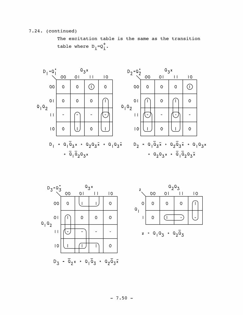
7.24. (continued)
The excitation table is the same as the transition
table where Di=Q+i.

- 7.51 -
7.24. (continued)
(b) Adjacency conditions to be satisfied:
Rule I: (C,E), (D,F), (B,E)
Rule II: (A,B), (C,F), (A,D), (C,E), (D,F), (D,E)
Rule III: (C,F)
State assignment map:
Transition table:
Present State(Q1Q2Q3)
Next State(Q+1Q
+2Q
+3)
Output(z)
Input (x)
0 1
A 000 000 001 0
B 001 111 110 0
C 111 010 000 1
D 010 011 111 0
E 011 010 110 0
F 110 011 010 1

- 7.52 -
7.24. (continued)
The excitation table is the same as the transition
table where Di=Q+i.

- 7.53 -
7.25. (a) Transition table:
Present State(Q1Q2Q3)
Next State(Q+1Q
+2Q
+3)
Output(z)
Input (x)
0 1
A 000 000 001 0
B 001 010 101 0
C 010 011 000 1
D 011 100 010 0
E 100 011 101 0
F 101 100 011 1
Excitation table:
Present state(Q1Q2Q3)
Excitation(J1K1,J2K2,J3K3)
Output(z)
Input (x)
0 1
000 0-,0-,0- 0-,0-,1- 0
001 0-,1-,-1 1-,0-,-0 0
010 0-,-0,1- 0-,-1,0- 1
011 1-,-1,-1 0-,-0,-1 0
100 -1,1-,1- -0,0-,1- 0
101 -0,0-,-1 -1,1-,-0 1

- 7.54 -
7.25. (continued)

- 7.55 -
7.25. (continued)

- 7.56 -
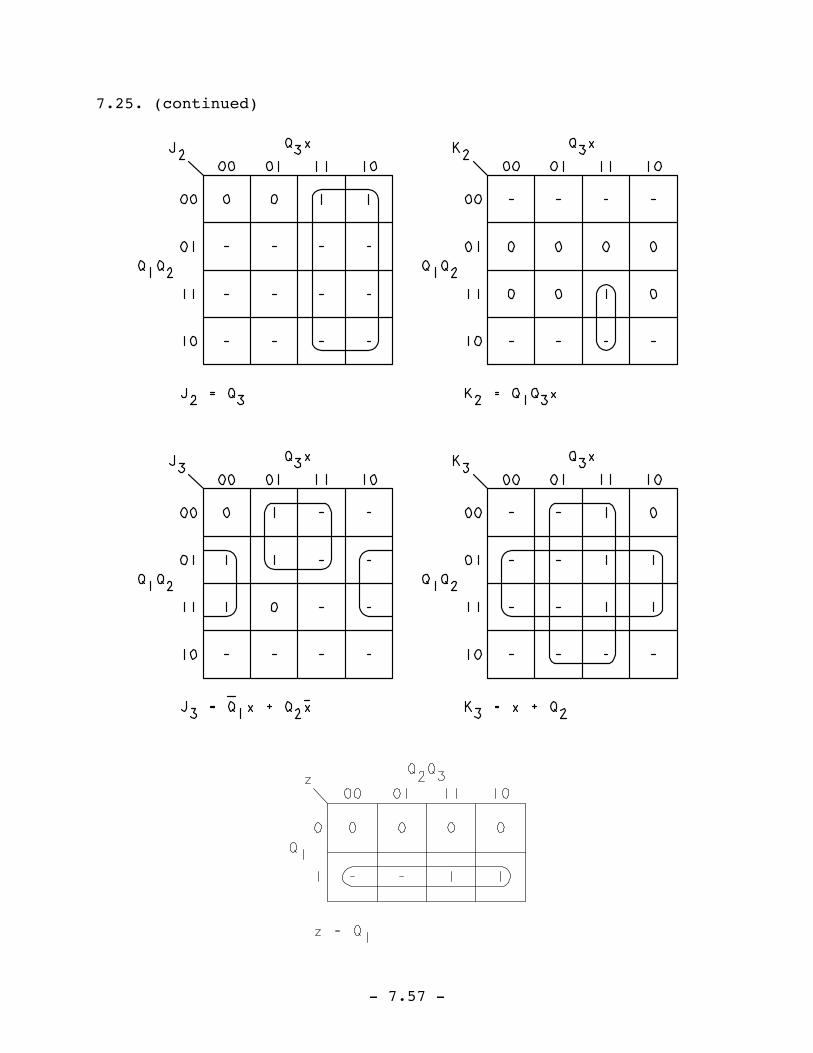
7.25. (continued)
(b) Use the state assignment established in Problem
7.24(b).
Excitation table:
Present state(Q1Q2Q3)
Excitation(J1K1,J2K2,J3K3)
Output(z)
Input (x)
0 1
000 0-,0-,0- 0-,0-,1- 0
001 1-,1-,-0 1-,1-,-1 0
111 -1,-0,-1 -1,-1,-1 1
010 0-,-0,1- 1-,-0,1- 0
011 0-,-0,-1 1-,-0,-1 0
110 -1,-0,1- -1,-0,0- 1
- 7.57 -
7.25. (continued)


![Chapter 7 [Chapter 7]](https://img.dokumen.tips/doc/110x75/61cd5ea79c524527e161fa6d/chapter-7-chapter-7.jpg)