Embed Size (px)
Citation preview

1
Chapter 6
Information Sources and
Signals

2
Big Idea in Data Communications: A conceptual framework for a data communications system. Multiple sources send to multiple destinations through an underlying physical channel
TX
RX
CH
Source
Compres.
Scramb.
Encoder
Modulator
Each of the boxes corresponds to one subtopic of data communications:

3
The Subtopics of Data Communications • Information Sources
– The source of information can be either analog or digital – Important concepts include characteristics of signals, such as
amplitude, frequency, and phase, and classification as either periodic or aperiodic
• Conversion between analog and digital representations of information
• Source Encoder and Decoder – Once information has been digitized, digital representations can be
transformed and converted – Concepts include data compression and consequences for
communications

4
The Subtopics of Data Communications • Encryptor and Decryptor
– To protect information and keep it private, the information can be encrypted (i.e., scrambled) before transmission and decrypted upon reception
– Concepts include cryptographic techniques and algorithms • Channel Encoder and Decoder
– Channel coding is used to detect and correct transmission errors – Topics include methods to detect and limit errors – Practical techniques like parity checking, checksums, and cyclic
redundancy codes that are employed in computer networks • Multiplexor and Demultiplexor
– Multiplexing refers to the way information from multiple sources is combined for transmission across a shared medium
– Concepts include techniques for simultaneous sharing as well as techniques that allow sources to take turns when using the medium

5
The Subtopics of Data Communications • Modulator and Demodulator
– Modulation refers to the way electromagnetic radiation is used to send information
– Concepts include both analog and digital modulation schemes – Devices known as modems that perform the modulation and
demodulation
• Physical Channel and Transmission – transmission media – transmission modes, such as serial and parallel – channel bandwidth – electrical noise and interference – channel capacity

6
Signals & Signal Sources

Signal Characteristics
• Analog (continuous) or digital (discrete)
• Periodic or aperiodic • Components of a periodic
electromagnet wave signal – Amplitude (maximum signal
strength) – e.g., in V – Frequency (rate at which the a
periodic signal repeats itself) – expressed in Hz
– Phase (measure of relative position in time within a single period) – in deg or radian (2π = 360 = 1 period)
S t A ftphase
A amplitudef frequncyT period f
( ) sin( )
/
= +
=
=
=
= =
2
1
π ϕ
ϕ
PeriodicS t S t T
:( ) ( )= +

Sound Wave Examples
Each signal is represented by x(t) = sin (2πf.t)
A dual tone signal with f1 and f2 is represented by x(t) = sin (2πf1.t) + sin (2πf2.t)
f = 5Kz
f = 1Kz

Taylor Series • Complex signals are often broken into simple pieces • Signal requirements
– Can be expressed into simpler problems – Is linear – The first few terms can approximate the signal
• Example: The Taylor series of a real or complex function ƒ(x) is the power series

Signal Representation
• Fourier Representation: We can represent all complex signals as harmonic series of simpler signals
• Frequency components of the square wave with amplitude A can be expressed as
∑∞
=
×=oddK k
kftAts/1
)2sin(4)( ππ

Square Wave
S(t)=sin(2πft)
S(t)=1/3[sin(2π(3f)t)]
S(t)= 4/π{sin(2πft) +1/3[sin(2π(3f)t)]}
∑∞
=
×=oddK k
kftAts/1
)2sin(4)( ππ

Example • http://www.phy.ntnu.edu.tw/ntnujava/index.php?topic=17

Square Wave
∑∞
=
×=oddK k
kftAts/1
)2sin(4)( ππ
Frequency Components of Square Wave
K=1,3,5 K=1,3,5, 7
K=1,3,5, 7, 9, ….. Fourier Expansion

Periodic Signals
• A Periodic signal/function can be approximated by a sum (possible infinite) sinusoidal signals.
• Consider a periodic signal with period T • A periodic signal can be Real or
Complex • The fundamental frequency: ωo • Example:
– Prove that x(t) is periodic:
oo
oo
tjo
TT
AetxComplex
ttxaltxnTtxPeriodic
o
ωπ
πω
θωω
/2/2
)(
)cos()(Re)()(
=
=
=→
+=→
=+⇒
)cos()( θω += ttx o
Note: cos(A + B) = cosAcosB - sinAsinB

Frequency Spectrum
• We can plot the frequency spectrum or line spectrum of a signal – In Fourier Series k represent
harmonics – Frequency spectrum is a graph that
shows the amplitudes and/or phases of the Fourier Series coefficients Ck.
• Amplitude spectrum |Ck|=4A/k.pi • The lines |Ck| are called line
spectra because we indicate the values by lines
∑∞
=
×=oddK k
kftAts/1
)2sin(4)( ππ
Examples • http://www.jhu.edu/~signals/listen-new/listen-newindex.htm
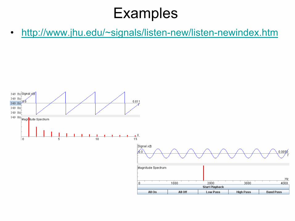
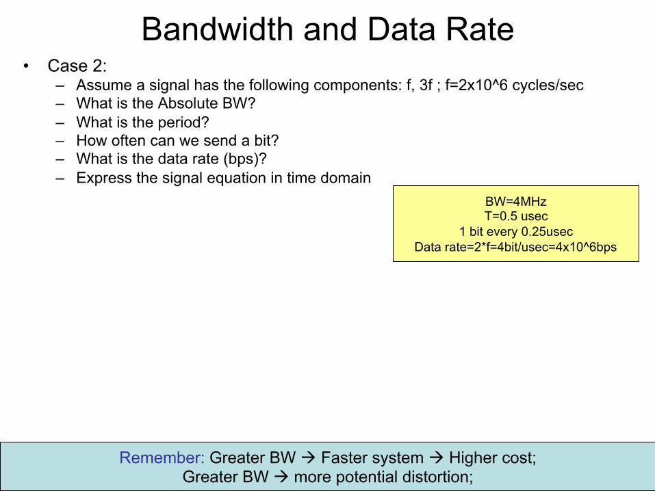
Periodic Signal Characteristics • A signal can be made of many frequencies
– All frequencies are multiple integer of the fundamental frequency
– Spectrum of a signal identifies the range of frequencies the signal contains
– Absolute bandwidth is defined as: Highest_Freq – Lowest_Freq
– Bandwidth in general is defined as the frequency ranges where a signal has its most of energies
• Signal data rate – Information carrying capacity of a signal – Expressed in bits per second (bps) – Typically, the larger frequency à larger data rate
Example à

Periodic Signals • Consider the following signal
– Consists of two freq. component (f) and (3f) with BW = 2f
S t ft f tFundamental freq fMax freq fAbs BW f f f
( ) ( / ) sin( ) ( / ) sin( ( ) )_
__
= +
=
=
= − =
4 2 4 3 2 3
33 2
π π π π
f 3f
BW
What is the Max amplitude of this component?
http://www.jhu.edu/~signals/listen-new/listen-newindex.htm
More complex signal
∑∞
=
×=oddK k
kftAts/1
)2sin(4)( ππ

Data Rate & Frequency
• Example: – What is the data rate in
case 1? – What is the data rate in
case 2? – Which case has larger
data rate? (sending more bits per unit of time)
0 1 0 0
1 0
Case 1: f1
1 msec
Case 2: f2
o Case I data rate=one bit per (0.25msec) n à 4 Kbps
o Case II: f2 = 1 KHz à data rate=2Kbps
o Case 1 has higher data rate (bps)

Bandwidth and Data Rate
• Case 1: – Assume a signal has the
following components: f, 3f, 5f ; f=10^6 cycles/sec
– What is the Absolute BW (Hz)?
– What is the period? – How often can we send a
bit? (bit/sec) – What is the data rate?
(bps) – Express the signal
equation in time domain
BW=4MHz T=1usec
1 bit every 0.5usec Data rate=2*f=2bit/usec=2Mbps
∑∞
=
×=oddK k
kftAts/1
)2sin(4)( ππ
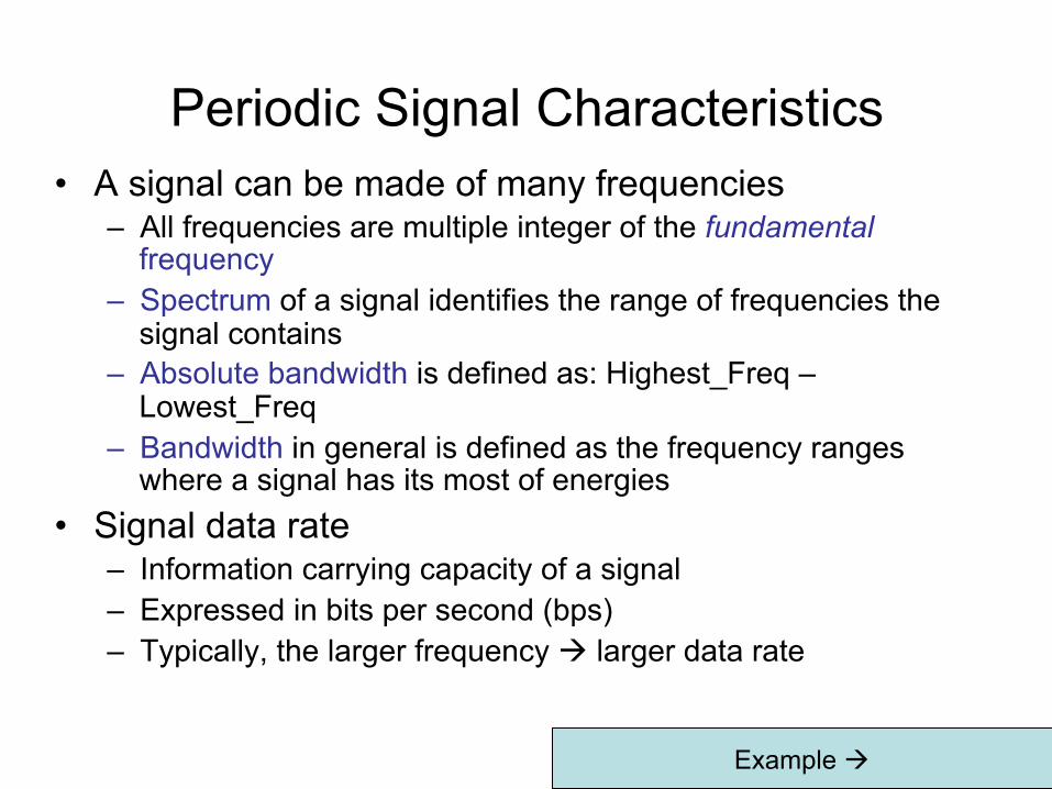
Bandwidth and Data Rate • Case 2:
– Assume a signal has the following components: f, 3f ; f=2x10^6 cycles/sec – What is the Absolute BW? – What is the period? – How often can we send a bit? – What is the data rate (bps)? – Express the signal equation in time domain
BW=4MHz T=0.5 usec
1 bit every 0.25usec Data rate=2*f=4bit/usec=4x10^6bps
Remember: Greater BW à Faster system à Higher cost; Greater BW à more potential distortion;

Typical Modulation and Coding
Encoder Decoder Medium Digital
g(t)Digital/Analog
g(t) Digitalx(t)
Modulator DemodulatorMedium Analog
m(t)Digital/Analog
m(t) Analogs(t)
Original D
ata
ASKFSK/BFSK/MFSKPSK/BPSK/MPSK
PCMPAMDM
AMPMFM
Signal Transmitted
Digital
Digital
Analog
Analog
NRZ/Multilevel/Biphase

What is Modulation or Encoding?
Changing signal characteristics including - Phase - Amplitude - Frequency Depending on the medium, signal range, and data Properties different encoding techniques can be used
Modulating signal
Modulated signal
With carrier frequency (fc)
ModulatorDigital/Analog
m(t) Analogs(t)

Reasons for Choosing Different Encoding/Modulation Techniques
• Digital data, digital signal – Less complex equipments – Less expensive than digital-to-analog modulation
equipment • Analog data, digital signal
– Permits use of modern digital transmission and switching equipment
– Requires conversion to analog prior to wireless transmission

Reasons for Choosing Encoding Techniques
• Digital data, analog signal – Some transmission media will only propagate analog
signals – E.g., optical fiber and unguided media
• Analog data, analog signal – Analog data in electrical form can be transmitted easily
and cheaply – Done with voice transmission over voice-grade lines
Used in Wireless!

Some Terms Ø Unipolar - signal elements have the same sign Ø Polar - One logic state represented by positive voltage Ø Bit Period - Duration or length of a bit Ø Modulation rate – baud rate Ø Remember:
Ø Modulation rate (baud) x log2 M = data rate (channel capacity) Ø M is the number of signal levels (symbols) Ø M = 2^L ; L is the number of bits used per symbol

Interpreting Digital Signals Ø Receiver needs to know
l timing of bits - when they start and end l signal levels
Ø Factors affecting signal interpretation l signal to noise ratio l data rate l bandwidth l encoding scheme – affects performance
• An increase in data rate increases bit error rate • An increase in SNR decreases bit error rate • An increase in bandwidth allows an increase in data rate
1- R ∝ BER 2- SNR ∝ 1/BER 3- BW ∝ BER

Signal Encoding Design Goals
– No DC components – No long sequence of zero-level line signals – No reduction in data rate – Error detection ability – Low cost

Encoding Schemes (Line Coding Mechanisms)

Nonreturn to Zero-Level (NRZ-L)
Ø two different voltages for 0 and 1 bits Ø 0= high level / 1 = low level

NRZI (Nonreturn to Zero – Invert on ones)
Ø Non-return to zero, inverted on ones Ø constant voltage pulse for duration of bit Ø data encoded as presence or absence of
signal transition at the beginning of bit time l Data is based on transitions (low to high or
high to low) – level change l Where there is a ONE à Transition occurs l Where there is a ZEROà No transition
occurs Ø Advantages
l data represented by changes rather than levels
l more reliable detection of transition rather than level – when noise exists!
NRZI Transition when we have
a ONE Otherwiseà no transition
NRZI is Differential encoding: information is transmitted based on changes between successive signal elements

Multilevel Binary Bipolar-AMI
Ø AMI stands for alternate mark inversion Ø Use more than two levels Ø Bipolar-AMI
l zero represented by no line signal l one represented by positive or negative pulse l One’s pulses alternate in polarity l no loss of sync if a long string of ones
l long runs of zeros still a problem l no net dc component l lower bandwidth l easy error detection
Bipolar - AMI 0 à 0
1,1à +,-

Multilevel Binary Pseudoternary
Ø one represented by absence of line signal
Ø zero represented by alternating positive and negative
Ø no advantage or disadvantage over bipolar-AMI
Ø each used in some applications
1 à 0 0,0à +,-

Multilevel Binary Issues
Ø synchronization with long runs of 0’s or 1’s l can insert additional bits, e.g.,ISDN l scramble data
Ø not as efficient as NRZ l each signal element only represents one bit
l receiver distinguishes between three levels: +A, -A, 0
l In a 3 level system each signal element (representing log23 = 1.58 bits) bears ONE bit of information l In this case 1.58 bits represent 1 bit of information! l Requires approx. 3dB more signal power for same probability
of bit error (lower S/N ratio) l the bit error rate for NRZ codes, at a given signal-to-noise ratio, is
significantly less than that for multilevel binary
http://en.wikipedia.org/wiki/Spectral_efficiency

The Spectral Efficiency (bps/Hz) & Modulation Efficiency (bit/symbol)
• The modulation efficiency in bit/s is the gross bitrate (including any error-correcting code) divided by the bandwidth ( = Bitrate/BW)
– Used to compare performance of different digital modulations
• Normalized Spectral Efficiency: Number of bits that can be propagated through the BW for each Hz à The more the better
• Example: A transmission technique using one kilohertz of bandwidth to transmit 1,000 bits per second has a modulation efficiency of 1 (bit/s)/Hz (1000bps/1KHz=1)
• Example: A V.92 modem for the telephone network can transfer 56,000 bit/s downstream and 48,000 bit/s upstream over an analog telephone network. Due to filtering in the telephone exchange, the frequency range is limited to between 300 hertz and 3,400 hertz, corresponding to a bandwidth of 3,400 − 300 = 3,100 hertz.
– The spectral efficiency or modulation efficiency is 56,000/3,100 = 18.1 (bit/s)/Hz downstream,
– 48,000/3,100 = 15.5 (bit/s)/Hz upstream

Example • For an 8-PSK (3 bits generating 8 symbols) system with bit
rate of 24 kbps find: – Baud (modulation rate) – Minimum BW – BW Efficiency
Baud = capacity or data rate / number of bits = = 24000/log2 8 = 8000 baud
BW = Channel capacity x number of bits = 8000 Hz BW Eff = Spectral Eff. = channel capacity / BW = 2400/8000 = 3

Manchester Encoding Ø has transition in the middle of each bit period Ø transition serves as clock and data Ø low to high represents one (1= 0 to 1) Ø high to low represents zero (0=1 to 0) Ø used by IEEE 802.3 - IEEE standards defining the Physical Layer and
Data Link Layer's media access control (MAC) sublayer of wired Ethernet

Differential Manchester Encoding
Ø Mid-bit transition is always there and represents clocking only
Ø transition at start of bit period representing 0 Ø no transition at start of bit period representing 1
l this is a differential encoding scheme Ø used by IEEE 802.5 - token ring LAN

Biphase Pros and Cons Ø Con
l at least one transition per bit time and possibly two (if differential) l maximum modulation rate is twice NRZ l requires more bandwidth
Ø Pros l synchronization on mid bit transition (self clocking) l has no dc component l has error detection

NRZ Pros & Cons Ø Pros
l easy to engineer l make good use of bandwidth
Ø Cons l dc component (too many ones or zeros; average is not zero)) l lack of synchronization capability
Ø Commonly used for magnetic recording Ø Not often used for signal transmission

Signal Element and Data Element
r = data_element / signal_element Best case is c! With only one signal element we are sending 2 bits!

Data Rate and Signal Rate • The data rate defines the number of bits sent per sec – bps.
– It is often referred to the bit rate.
• The signal rate is the number of signal elements sent in a second and is measured in bauds . – It is also referred to as the modulation rate or baud rate
• Goal is to increase the data rate whilst reducing the baud rate

Data Rate and Baud Rate • The baud or signal rate can be expressed as:
D = c x R x 1/r ( in bauds) Where R is data rate
c is the case factor (worst, best & avg.) r is the ratio between data element & signal element
The Goal is to increase the data rate whilst reducing the baud rate (c=const.): r = R/D à We want higher r
r = data_element / signal_element

Example
A signal is carrying data in which one data element is encoded as one signal element ( r = 1). If the bit rate is 100 kbps, what is the average value of the baud rate if c is between 0 and 1 (c=1/2)? Solution We assume that the average value of c is 1/2 . The baud rate is then
D=cxRx1/r = 0.5x1000x1=50 kbaud

Example • Using NRZI, how do you represent 1 1 1 1 1? • Assuming it takes 5usec to send 5 bits what is
the duration of each bit? • Assuming it takes 5usec to send 5 bits what is
the duration of each signal element? – The signal will be 0 1 0 1 0 (toggling – starting
with Zero as the initial state) – Each bit = 1 usec – Each signal element = 1 usec
• Using Manchester, how do you represent 1 1 1 1 1?
– The signal will be 01 01 01 01 01 (toggling in the middle of each bit – starting with Zero as the initial state)
– Each bit = 1 usec – Each signal element = 0.5 usec
r=1
r=1/2
Note that in Bipolar maximum modulation rate is twice NRZ c=1; R=constant D = R/r NOT GOOD! We want D to decrease R to increase!

Scrambling • The objective is to avoid long sequences of zero level line
signals and providing some type of error detection capability • We compare two techniques:
– B3ZS (bipolar 8-zero substitution) – HDB3 (High-density Bipolar-3 zeros)
B8ZS: One octet of zero is replaced by: 000VB0VB V = 1 code violation

Scrambling • The objective is to avoid long sequences of zero level line
signals and providing some type of error detection capability • We compare two techniques:
– B3ZS (bipolar 8-zero substitution) – HDB3 (High-density Bipolar-3 zeros)
HDB3: 4 zeros are replaced by: - 000V if the number of pulses (ones) since last substitution was ODD - B00V if the number of pulses (ones) since last substitution was EVEN V = 1code violation

Basic Encoding Techniques
• Analog data to digital signal – Pulse code modulation (PCM) – Delta modulation (DM)
• Basic process of digitizing analog data O
riginal Data
ASKFSK/BFSK/MFSKPSK/BPSK/MPSK
PCMDM
AMPMFM
Signal Transmitted
Digital
Digital
Analog
Analog

The Nyquist Theorem and Sampling Rate • An analog signal must be sampled in PCM or DM • How frequently should an analog signal be sampled?
– Taking too few samples (undersampling) means that the digital values only give a crude approximation of the original signal
– Taking too many samples (oversampling) means that more digital data will be generated, which uses extra bandwidth
• A mathematician named Nyquist discovered the answer to the question of how much sampling is required:
– where fmax is the highest frequency in the composite signal • Nyquist Theorem provides a practical solution to the problem:
– sample a signal at least twice as fast as the highest frequency that must be preserved

Pulse Code Modulation • Based on the sampling theorem • Each analog sample is assigned a binary code
– Analog samples are referred to as pulse amplitude modulation (PAM) samples
• The digital signal consists of block of n bits, where each n-bit number is the amplitude of a PCM pulse

Pulse Code Modulation
1- Sampling frequency (two times fmax) 2- Quantization levels (number of bits available)

Pulse Code Modulation • By quantizing the PAM pulse, original signal is only
approximated – More quantization levels à more accurate signal
approximation à more complex system • Leads to quantizing noise • Signal-to-noise ratio for quantizing noise
– n being the number of bits used for quantization
dB 76.102.6dB 76.12log20SNRdB +=+= nn
NOTE: each additional bit increases SNR by 6 dB, or a factor of 4

Signal to quantization noise ratio (SQNR)
The root mean square value of the sine wave signal
The error signal lies uniformly in the range [+/-1/2^b]; thus the root mean square value of the error signal
NOTE: b=n being the number of bits used for quantization

Example: • Assuming we use 7 bits to reconstruct the voice signal.
Bandwidth of voice signal is 4KHz. – How may quantization levels can we create? – What is the sampling rate for the voice signal? (Nyquist Theorem) – What is the BW of the PCM-encoded digital signal? (bps) – What is the minimum frequency (Hz) required to carry the voice
signal? – How much the S/N (in dB) will increase if we use 9 bits instead?
• 2^7 = 128 levels • Sampling rate: 2f = 8KHz (8000 samples / sec) ß according to the sampling theorem • Each sample has 7 bits • PCM BW = 8000 sample/sec x 7 bit/sample = 56 Kbit/sec à data rate • Remember if rate of the signal is 2f then a signal with frequencies no greater than f is sufficient to carry the signal rate. à f=28 KHz. ( this is in the absence of noise!!!) • each additional bit increases SNR by 6 dB, or a factor of 4 à 12 dB.

Delta Modulation
• Analog input is approximated by staircase function – Moves up or down by one quantization level (δ) at each sampling
interval
• Only the change of information is sent – only an increase or decrease of the signal amplitude from the
previous sample is sent – a no-change condition causes the modulated signal to remain at
the same 0 or 1 state of the previous sample

Delta Modulation • Two important parameters
– Size of step assigned to each binary digit (δ) – Sampling rate
• Accuracy improved by increasing sampling rate – However, this increases the data rate
• Advantage of DM over PCM is the simplicity of its implementation