Embed Size (px)
Citation preview
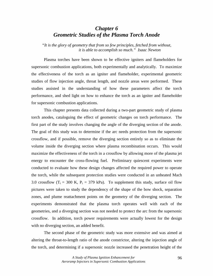
A Study of Plasma Ignition Enhancement for Aeroramp Injectors in Supersonic Combustion Applications
96
Chapter 6 Geometric Studies of the Plasma Torch Anode
“It is the glory of geometry that from so few principles, fetched from without,
it is able to accomplish so much.” Isaac Newton
Plasma torches have been shown to be effective igniters and flameholders for
supersonic combustion applications, both experimentally and analytically. To maximize
the effectiveness of the torch as an igniter and flameholder, experimental geometric
studies of flow injection angle, throat length, and nozzle areas were performed. These
studies assisted in the understanding of how these parameters affect the torch
performance, and shed light on how to enhance the torch as an igniter and flameholder
for supersonic combustion applications.
This chapter presents data collected during a two-part geometric study of plasma
torch anodes, cataloguing the effect of geometric changes on torch performance. The
first part of the study involves changing the angle of the diverging section of the anode.
The goal of this study was to determine if the arc needs protection from the supersonic
crossflow, and if possible, remove the diverging section entirely so as to eliminate the
volume inside the diverging section where plasma recombination occurs. This would
maximize the effectiveness of the torch in a crossflow by allowing more of the plasma jet
energy to encounter the cross-flowing fuel. Preliminary quiescent experiments were
conducted to evaluate how these design changes affected the required power to operate
the torch, while the subsequent protection studies were conducted in an unheated Mach
3.0 crossflow (Tt = 300 K, Pt = 379 kPa). To supplement this study, surface oil flow
pictures were taken to study the dependency of the shape of the bow shock, separation
zones, and plume reattachment points on the geometry of the diverging section. The
experiments demonstrated that the plasma torch operates well with each of the
geometries, and a diverging section was not needed to protect the arc from the supersonic
crossflow. In addition, torch power requirements were actually lowest for the design
with no diverging section, an added benefit.
The second phase of the geometric study was more extensive and was aimed at
altering the throat-to-length ratio of the anode constrictor, altering the injection angle of
the torch, and determining if a supersonic nozzle increased the penetration height of the

A Study of Plasma Ignition Enhancement for Aeroramp Injectors in Supersonic Combustion Applications
97
plasma jet. Evaluations of the designs were made using thermodynamic probing and
spectroscopic analyses of the plasma jet. A spectrometer was used to measure the
spectral intensity of the Hβ line from the Balmer series at the torch exit for torch input
powers between 1 and 4.5 kW. Excited hydrogen atoms were chosen as the specie to
track, since hydrogen atoms are known to enhance combustion. Downstream
temperature probes measured the total temperature of the torch plume to determine how
the plume height and shape changed for various geometries and operational conditions.
In addition, stereoscopic photographs of the anode surfaces were taken after the tests
were complete to provide a better understanding of how geometric changes affect arc
attachment and anode wear rate. Evaluation of spectral and temperature data
demonstrated that anodes designed for normal injection produced higher spectral
intensities within the jet, and higher total temperatures downstream of the torch, when
compared to anodes designed for transverse injection. The combination of these two
observations indicates a greater ignition potential. Comparisons of the anode constrictor
lengths showed that longer constrictors, although producing higher jet intensities, are
unstable due to the longer arc column. Finally, supersonic nozzles were found to increase
the total temperature of the downstream plumes, but had poor penetration and failed to
eject any plasma above the tunnel floor for powers less than 1700 W.
6.2: Test Procedure
6.2.1: Anode Exit Geometry
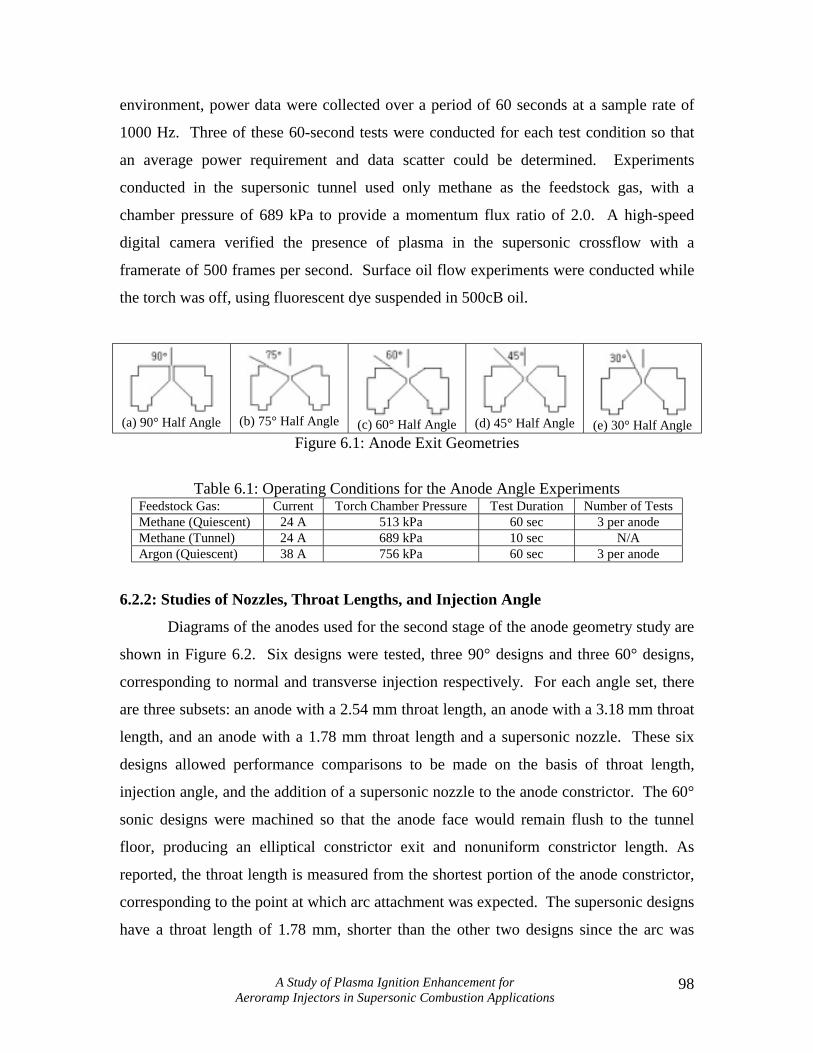
The tests designed to study the effect of changing the angle of the diverging
section of the anode were conducted using VTPT-2 with tungsten anodes. The anodes
used to study the effect of the anode diverging section on torch performance are shown in
Figure 6.1. The throat length for each design was kept constant at 1.02 mm, except for
the 90° case, which had a longer throat length of 2.26 mm. This difference was tolerated
because it was necessary to keep the overall height of the anode the same so that the
anode surface would be flush with the tunnel floor in the supersonic crossflow
experiments. The operating conditions for the tests are shown in Table 6.1. Values for
pressure and current were selected to produce high powers, allowing changes in torch
power for different anode geometries to be more easily identified. In the quiescent
A Study of Plasma Ignition Enhancement for Aeroramp Injectors in Supersonic Combustion Applications
98
environment, power data were collected over a period of 60 seconds at a sample rate of
1000 Hz. Three of these 60-second tests were conducted for each test condition so that
an average power requirement and data scatter could be determined. Experiments
conducted in the supersonic tunnel used only methane as the feedstock gas, with a
chamber pressure of 689 kPa to provide a momentum flux ratio of 2.0. A high-speed
digital camera verified the presence of plasma in the supersonic crossflow with a
framerate of 500 frames per second. Surface oil flow experiments were conducted while
the torch was off, using fluorescent dye suspended in 500cB oil.
(a) 90° Half Angle
(b) 75° Half Angle
(c) 60° Half Angle
(d) 45° Half Angle
(e) 30° Half Angle Figure 6.1: Anode Exit Geometries
Table 6.1: Operating Conditions for the Anode Angle Experiments
Feedstock Gas: Current Torch Chamber Pressure Test Duration Number of Tests Methane (Quiescent) 24 A 513 kPa 60 sec 3 per anode Methane (Tunnel) 24 A 689 kPa 10 sec N/A Argon (Quiescent) 38 A 756 kPa 60 sec 3 per anode
6.2.2: Studies of Nozzles, Throat Lengths, and Injection Angle
Diagrams of the anodes used for the second stage of the anode geometry study are
shown in Figure 6.2. Six designs were tested, three 90° designs and three 60° designs,
corresponding to normal and transverse injection respectively. For each angle set, there
are three subsets: an anode with a 2.54 mm throat length, an anode with a 3.18 mm throat
length, and an anode with a 1.78 mm throat length and a supersonic nozzle. These six
designs allowed performance comparisons to be made on the basis of throat length,
injection angle, and the addition of a supersonic nozzle to the anode constrictor. The 60°
sonic designs were machined so that the anode face would remain flush to the tunnel
floor, producing an elliptical constrictor exit and nonuniform constrictor length. As
reported, the throat length is measured from the shortest portion of the anode constrictor,
corresponding to the point at which arc attachment was expected. The supersonic designs
have a throat length of 1.78 mm, shorter than the other two designs since the arc was

A Study of Plasma Ignition Enhancement for Aeroramp Injectors in Supersonic Combustion Applications
99
expected to attach outside of the throat. It was desired to keep the arc length of the
supersonic anodes comparable to the short-throated designs. Therefore, the throat length
of the supersonic design was chosen assuming the arc attached one-third the distance up
the nozzle based on past experience (Gallimore, 1998). To facilitate easy discussion,
these designs are referred to by their injection angle, followed by the anode geometry
description, as shown in Figure 6.2. (Ex. The 60° anode with the 3.18 mm throat will be
referred to as the 60°-sonic-long anode design.) Each design was tested in a Mach 2.4
crossflow, with power ranging from 1-4.5 kW and momentum flux ratios of 1.17 or 2.34.
(a) 90°, 2.54 mm Throat
(90°-sonic)
(b) 90°, 3.18 mm Throat
(90°-sonic-long)
(c) 90° Supersonic Throat
(90°-supersonic)
(d) 60°, 2.54 mm Throat
(60°-sonic)
(e) 60°, 3.18 mm Throat
(60°-sonic-long)
(f) 60° Supersonic Throat
(60°-supersonic)
Figure 6.2: Anode Designs for the Nozzle, Throat Geometry and Injection Angle Study
6.2.3: Stereoscopic Investigation of Anode Wear
Magnified optical evaluations of the anode surfaces were made by use of a
stereoscope, which could be used to take pictures of the anode surfaces. The
observations made of the anode surfaces showed where the arc attachment point was
located, whether or not the arc attachment point moved during operation, and how the arc
changed the shape of the anode surface through erosion. This type of investigation
resulted in a better understanding of the type of anode wear associated with various
geometric features.

A Study of Plasma Ignition Enhancement for Aeroramp Injectors in Supersonic Combustion Applications
100
6.3: Results and Discussion
The results are presented in two separate sections, the first discussing the
geometric study of the diverging section of the anode, and the second an investigation of
the effects of supersonic nozzles, throat length, and injection angle on torch performance.
The discussion of the second study is presented in such a way that comparisons of the six
designs are presented first, followed by subsections discussing operational trends for each
specific design.
6.3.1: Studies of the Anode Diverging Section
Regarding the investigations of the effect that the anode diverging section has on
the operability of the torch, the main result is that the torch was observed to light in a
Mach 3.0 crossflow for all anode designs (refer to Figure 6.1), even with no diverging
section present to protect the arc. In addition, power requirements for anodes with
constant diameter exit nozzles were generally lower than for anodes with a diverging
section.
6.3.1.1: Results of the Power Requirements
As expected, experiments with argon produced smooth operation for all tests.
The results were repeatable and produced power readings that fluctuated very little from
the mean reported values in Figure 6.3. From the figure, it is clear that the 45° design
requires the most power to operate, while the other designs require about 20% less. Since
current was held constant, these power differences are due solely to the voltage
requirements, which is a combined effect of both the arc length and arc shape. Analysis
of the anodes after testing showed that the arc attachment point for the 45° case was
slightly outside the anode throat in the diverging section, while for the 60° and 75°
designs the arc attachment point was at the boundary of the throat and diverging section.
From this, conclusions can be drawn that a shorter arc length caused, at least in part, the
lower voltage requirements for the 60° and 75° cases. Although the 90° design has the
longest anode constrictor, it experienced the lowest power of all four designs, which is
quite significant. The voltage requirements for this geometry were less, because there
was less arc curvature (Somerville, 1959), but also may be attributed to radius of
A Study of Plasma Ignition Enhancement for Aeroramp Injectors in Supersonic Combustion Applications
101
curvature effects on the electric field (refer to Section 4.3.4.2). Slight anode wear at the
constrictor exit proved that the arc traveled the entire length of the constrictor.
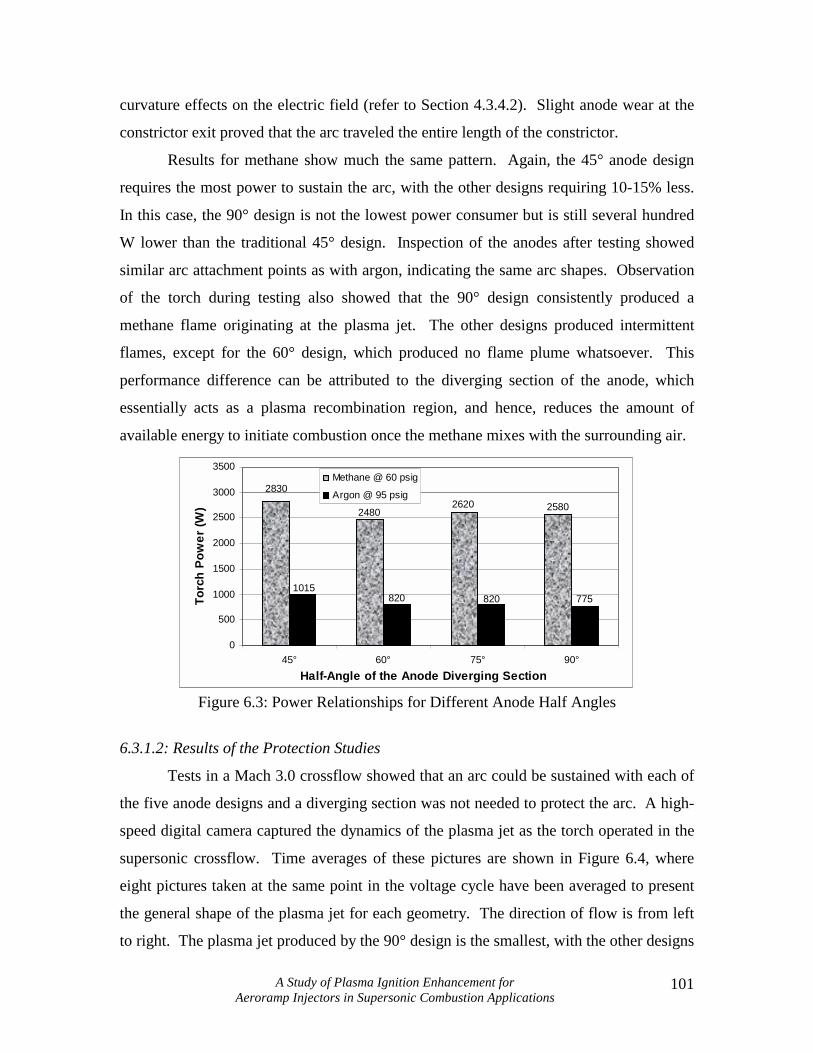
Results for methane show much the same pattern. Again, the 45° anode design
requires the most power to sustain the arc, with the other designs requiring 10-15% less.
In this case, the 90° design is not the lowest power consumer but is still several hundred
W lower than the traditional 45° design. Inspection of the anodes after testing showed
similar arc attachment points as with argon, indicating the same arc shapes. Observation
of the torch during testing also showed that the 90° design consistently produced a
methane flame originating at the plasma jet. The other designs produced intermittent
flames, except for the 60° design, which produced no flame plume whatsoever. This
performance difference can be attributed to the diverging section of the anode, which
essentially acts as a plasma recombination region, and hence, reduces the amount of
available energy to initiate combustion once the methane mixes with the surrounding air.
2830
258026202480
7758208201015
0
500
1000
1500
2000
2500
3000
3500
45° 60° 75° 90°Half-Angle of the Anode Diverging Section
Torc
h Po
wer
(W)
Methane @ 60 psig
Argon @ 95 psig
Figure 6.3: Power Relationships for Different Anode Half Angles
6.3.1.2: Results of the Protection Studies
Tests in a Mach 3.0 crossflow showed that an arc could be sustained with each of
the five anode designs and a diverging section was not needed to protect the arc. A high-
speed digital camera captured the dynamics of the plasma jet as the torch operated in the
supersonic crossflow. Time averages of these pictures are shown in Figure 6.4, where
eight pictures taken at the same point in the voltage cycle have been averaged to present
the general shape of the plasma jet for each geometry. The direction of flow is from left
to right. The plasma jet produced by the 90° design is the smallest, with the other designs

A Study of Plasma Ignition Enhancement for Aeroramp Injectors in Supersonic Combustion Applications
102
being larger to varying degrees. However, the smaller size of the plasma jet does not
necessarily imply lower ignition potential since the energy density of the plasma jets
could not be determined with these techniques. Furthermore, the plasma jet produced by
the 90° design penetrates slightly further than the other designs, a desirable characteristic
for igniting cross-flowing fuel-air mixtures.
(a) 90° Half Angle
(b) 75° Half Angle
(c) 60° Half Angle
(d) 45° Half Angle
(e) 30° Half Angle Figure 6.4: High-speed Photographs of Torch Operation in a Mach 3.0 Crossflow
Finally, surface oil-flow visualization techniques were used to study the effects of
the anode diverging section on the local flowfield. Pictures of the oil flows are shown in
Figure 6.5 for a Mach number of 3.0, no power, and a momentum flux ratio of 2.0. Flow
is from top to bottom. The dark circle outlines the interface of the torch anode (d=2.1cm)
and tunnel floor. The pictures demonstrate that the anode geometry strongly influences
the shape and size of the separation regions in front and behind the torch exit. The 90°
design appears to have the largest separation region as well as the widest bow shock.
(a) 90° Half Angle
(b) 75° Half Angle
(c) 60° Half Angle
(d) 45° Half Angle
(e) 30° Half Angle
Figure 6.5: Surface Oil Flow Photographs of Torch Operation in a Mach 3.0 Crossflow

A Study of Plasma Ignition Enhancement for Aeroramp Injectors in Supersonic Combustion Applications
103
6.3.2: Geometric Study of Nozzles, Throat Lengths and Injection Angle
This section presents a comparison of the six geometric designs tested (refer to
Figure 6.2), followed by subsections discussing specific features of each design. Four
types of data are presented: spectral exit profiles, 2D-Hβ profiles, total temperature plots,
and stereoscopic photographs of the anode surfaces. Procedures for collecting these
forms of data were outlined in Chapter 3. Spectral exit profiles are used to determine the
stability of a design, whereas the 2D-Hβ profiles can be used to qualitatively compare the
energy density contained within the plasma. An example of a spectral exit profile for the
Hβ line is shown in Figure 6.6, and is a representation of the line intensity at various
points across the torch exit, located at x=0. Total temperature plots are used to ascertain
the penetration height of the thermal energy, and can be used to estimate the mixing
effectiveness of such a design. Stereoscopic photographs show arc attachment point
locations and whether or not the arc moved during operation.
Figure 6.6: An Example of Spectral Exit Profile
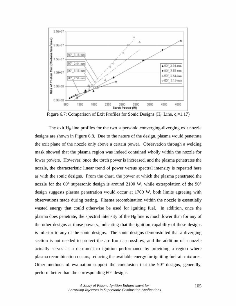
In general, it was discovered that 60° designs produced plasmas with higher exit
intensities for the Hβ line than the corresponding 90° design. Figures 6.7 and 6.8 show
the maxima of these exit profiles for each of the six designs, at various powers and a
torch momentum flux ratio of 1.17. It is clear that for each sonic design the intensity of
the Hβ line exhibits a linear dependence on the torch input power. In general, 60° designs
had higher slopes than the 90° counterparts, and anodes with longer throat lengths
produced higher slopes than anodes with shorter throats.

A Study of Plasma Ignition Enhancement for Aeroramp Injectors in Supersonic Combustion Applications
104
Through observation of the torch during testing, the slope and x-intercept of these
linear trend lines are believed to have significance. The slope of the trend line is thought
to be a measure of arc stability, with steeper-sloped designs exhibiting less stability. The
two 60°-sonic designs have steeper slopes than the 90°-sonic designs, and suggest that
the elliptical exit geometry might be a source of instability because the arc attachment
point is fixed at a point where the anode wall is thin and prone to erosion. In addition,
long-throated designs were observed to suffer from starting problems, and consequently,
also produced exit profiles with larger slopes than short-throated designs.
The x-intercepts of the trend lines indicate the theoretical lowest possible power at
which the torch can be operated. Consequently, this intercept corresponds to a zero-
radical production rate. Referring to Figure 6.7, the x-intercepts of each design can be
determined by extrapolating the linear trend lines. Table 6.2 lists the designs with their
corresponding x-intercept. Both Figure 6.7 and Table 6.2 suggest that the 90°-sonic
design would be the most stable design, and have the ability to operate at lower power
levels than the other five designs. From observation during numerous tests, this was
certainly the case. The 90°-sonic design had excellent durability and startability
characteristics. Furthermore, 60° designs had higher trend line slopes, and consequently
were less stable at lower powers. The 90°-sonic-long design is the only design that does
not fit this trend. It had poor starting characteristics and was quite unstable except above
2500 W. The slope of the trend line for this design would indicate that, although less
stable than the 90°-sonic design, it would have better stability characteristics than the 60°
designs. However, for this particular test series this was not the case.
Table 6.2: X-intercepts for the Six Anode Designs Anode Design X-Intercept 90°-sonic 700 W 90°-sonic-long 1000 W 90°-supersonic 1700 W* 60°-sonic 1000 W 60°-sonic-long 1250 W 60°-supersonic 2100 W*
*- Indicates limit of plasma penetration
A Study of Plasma Ignition Enhancement for Aeroramp Injectors in Supersonic Combustion Applications
105
Figure 6.7: Comparison of Exit Profiles for Sonic Designs (Hβ Line, qt=1.17)
The exit Hβ line profiles for the two supersonic converging-diverging exit nozzle
designs are shown in Figure 6.8. Due to the nature of the design, plasma would penetrate
the exit plane of the nozzle only above a certain power. Observation through a welding
mask showed that the plasma region was indeed contained wholly within the nozzle for
lower powers. However, once the torch power is increased, and the plasma penetrates the
nozzle, the characteristic linear trend of power versus spectral intensity is repeated here
as with the sonic designs. From the chart, the power at which the plasma penetrated the
nozzle for the 60° supersonic design is around 2100 W, while extrapolation of the 90°
design suggests plasma penetration would occur at 1700 W, both limits agreeing with
observations made during testing. Plasma recombination within the nozzle is essentially
wasted energy that could otherwise be used for igniting fuel. In addition, once the
plasma does penetrate, the spectral intensity of the Hβ line is much lower than for any of
the other designs at those powers, indicating that the ignition capability of these designs
is inferior to any of the sonic designs. The sonic designs demonstrated that a diverging
section is not needed to protect the arc from a crossflow, and the addition of a nozzle
actually serves as a detriment to ignition performance by providing a region where
plasma recombination occurs, reducing the available energy for igniting fuel-air mixtures.
Other methods of evaluation support the conclusion that the 90° designs, generally,
perform better than the corresponding 60° designs.

A Study of Plasma Ignition Enhancement for Aeroramp Injectors in Supersonic Combustion Applications
106
0.0E+00
1.0E+06
2.0E+06
3.0E+06
4.0E+06
5.0E+06
6.0E+06
7.0E+06
8.0E+06
800 1300 1800 2300 2800 3300
Torch Power (W)
Rate
of P
hoto
n Fl
ux (P
hoto
ns/m
m2 /s
ec)
90°_SS
60°_SS
Figure 6.8: Comparison of Exit Profiles for Supersonic Designs (Hβ Line, qbar=1.17)
Downstream total temperature measurements were used to measure the
penetration height of the thermal energy from the plasma jet, and provided a means to
compare the energy content of the gas from one test condition to another. Figure 6.9
presents centerline total temperature measurements for four of the designs at 1500 and
2500 W. The profiles of the sonic-long designs have been omitted for clarity, but are
included in sections 6.3.2.2 and 6.3.2.5. From the two charts, several trends can be
identified. The first trend is that the two 90° designs have higher maximum total
temperature ratios than the 60° designs, indicating the 90° designs may impart more
thermal energy to the feedstock gas. As will be shown in the following subsections, this
agrees well with the two-dimensional spectral data taken of the plasma jets. In addition,
the penetration heights of the 90° designs are higher than the 60° designs, which indicates
that normal injection may increase the ignition potential of a plasma torch design by
increasing the effective distance at which the jet interacts with fuel molecules.

A Study of Plasma Ignition Enhancement for Aeroramp Injectors in Supersonic Combustion Applications
107
(a) Centerlines at 1500 W
(b) Centerlines at 2500 W
Figure 6.9: Centerline Temperature Profiles Comparing Power
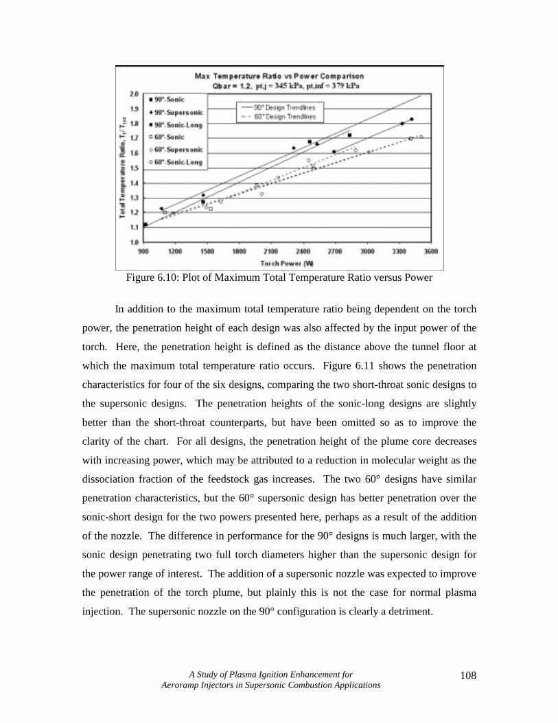
The maxima of the profiles presented in Figure 6.9, are plotted in Figure 6.10,
along with the maxima of other profiles at different powers. For each of the six designs,
it appears that the maximum total temperature exhibits a linear dependence on the torch
input power. All designs produce near equal slopes, but the offset of the lines is due to
the geometry of the anode. The 90° designs all produce higher maxima than the 60°
designs, indicating a larger amount of input energy to the feedstock gas. The
measurement of these maxima could be used as a qualitative indication of torch
efficiency when calorimeters are unavailable. In addition, the designs tend to cluster
together as a function of the injection angle. Both 60° and 90° designs, respectively,
perform quite similarly, producing nearly equivalent maximum total temperature ratios
throughout the power range of interest. Unexpectedly, the 90°-sonic design produced
higher maximum total temperature ratios than the 90°-sonic-long design, the opposite
trend experienced with the 60° designs. This could be attributed to the poor stability of
the design, or the possibility that the measurements were taken off the centerline of the
temperature plume. The latter is more feasible as the centerline was observed to change
location occasionally. Regardless, the maximum total temperature ratios measured with
the 90°-sonic-long design are still higher than any of the 60° designs, which fit the trend.
A Study of Plasma Ignition Enhancement for Aeroramp Injectors in Supersonic Combustion Applications
108
Figure 6.10: Plot of Maximum Total Temperature Ratio versus Power
In addition to the maximum total temperature ratio being dependent on the torch
power, the penetration height of each design was also affected by the input power of the
torch. Here, the penetration height is defined as the distance above the tunnel floor at
which the maximum total temperature ratio occurs. Figure 6.11 shows the penetration
characteristics for four of the six designs, comparing the two short-throat sonic designs to
the supersonic designs. The penetration heights of the sonic-long designs are slightly
better than the short-throat counterparts, but have been omitted so as to improve the
clarity of the chart. For all designs, the penetration height of the plume core decreases
with increasing power, which may be attributed to a reduction in molecular weight as the
dissociation fraction of the feedstock gas increases. The two 60° designs have similar
penetration characteristics, but the 60° supersonic design has better penetration over the
sonic-short design for the two powers presented here, perhaps as a result of the addition
of the nozzle. The difference in performance for the 90° designs is much larger, with the
sonic design penetrating two full torch diameters higher than the supersonic design for
the power range of interest. The addition of a supersonic nozzle was expected to improve
the penetration of the torch plume, but plainly this is not the case for normal plasma
injection. The supersonic nozzle on the 90° configuration is clearly a detriment.

A Study of Plasma Ignition Enhancement for Aeroramp Injectors in Supersonic Combustion Applications
109
Figure 6.11: Penetration Height versus Power
At this point, a question may arise at the apparent disparity between the spectral
exit profiles in Figure 6.7 and the total temperature measurements in Figure 6.10. Why
do the 90° designs exhibit lower spectral jet intensities, but higher total temperature
ratios? These phenomena seem contradictory, as both are indicative of the energy
contained within the feedstock gas, but are actually in sound agreement. This difference
is attributed to the geometry of the arc. Arc geometry heavily influences the amount of
energy imparted to a feedstock gas, and is a function of the temperature difference
between the arc and surrounding gas. The heat, ∆H, carried away from the arc by
convection in a cylinder of radius r and thickness dr is
TCrdrH p ∆=∆ ρυπ2 , (6.1)
where υ is the uniform velocity of the gas, Cp is the specific heat of the gas, and ρ is the
density (Cobine, 1941). A temperature gradient of several thousand degrees per
millimeter exists in the gas directly surrounding the arc. Consequently, as the
temperature of the surrounding gas approaches that of the arc, the heat transfer to the gas
decreases. Furthermore, the temperature of the gas is also a function of the concentration
of the ionized atoms within the gas according to the Saha equation
kTeVi
Txpx
x −−=−
ε5.272
2
1016.31
(6.2)
where T is the temperature of the gas in Kelvin, and x is the fraction of ionized atoms
within the gas (Cobine, 1941). From Equations 6.1 and 6.2, it is evident that stationary
arcs, producing high local temperatures and ion concentrations, will consequently impart

A Study of Plasma Ignition Enhancement for Aeroramp Injectors in Supersonic Combustion Applications
110
less overall thermal energy to the feedstock gas because of the lack of arc motion and a
lower temperature gradient between the arc and surrounding gases. This concept is
illustrated in Figure 6.12. Notice that in the case of the dynamic arc, the maximum
temperature near the arc centerline is lower than for the static arc, but the overall bulk
temperature is higher.
0 0.2 0.4 0.6 0.8 1Radial Distance (r/R)
Tem
pera
ture
(K)
Static ArcDynamic Arc
Figure 6.12: Illustration of the Relationship Between Arc Motion
and Temperature Distributions
From the present experiments, anodes used for transverse injection, with elliptical
exit areas, exhibited less arc movement than did anodes used for normal injection.
Assuming the arcs produced with both designs are of equal lengths, the design producing
a static arc will create higher centerline temperatures within the constrictor but impart
less overall energy to the feedstock gas as a result. Upon exit, these gases will have a
higher energy density at the center of the constrictor but have a lower bulk energy density
than plasma produced by a dynamic arc. Spectrally, these plasmas will appear brighter at
the centerline of the constrictor exit, which was observed. However, after mixing with
surrounding gases these plasmas will produce lower total temperature measurements
downstream. Comparisons of spectral exit and 2D profiles in the following sections will
show that 60° designs do indeed produce higher spectral intensities at the exit, but when
integrated over the entire plasma jet, produce a lower average rate of photon flux
indicating lower energy density, as would be expected.

A Study of Plasma Ignition Enhancement for Aeroramp Injectors in Supersonic Combustion Applications
111
6.3.2.1: Results for the 90°, 2.54-mm Throat Length, Sonic Anode
The 90°-sonic design turned out to be the most stable design tested, with a wide
operational power range. The performance of this design was consistent from anode to
anode, as well as throughout the lifecycle of the anode, producing repeatable results from
the first run to the time it was replaced.
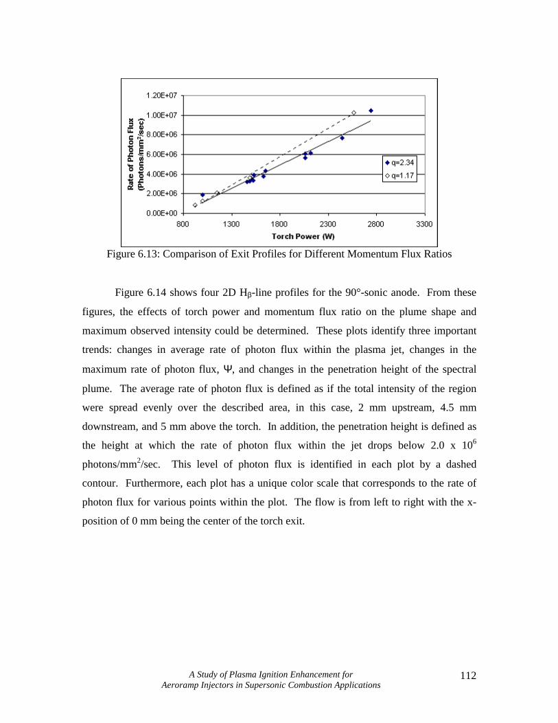
Figure 6.13 presents the results from the mass flowrate experiments for methane
and the effect mass flowrate has on the Hβ line for a range of powers. Here, the mass
flowrate is expressed as a momentum flux ratio, for which a conversion can be found in
Appendix C. From the chart, the maximum intensity of the Hβ line is observed to
decrease for higher mass flowrates. This is a combination of two effects, the constriction
of the arc, and the increase in thermal mass of the feedstock gas. An increase in thermal
mass reduces the temperature rise of the feedstock gas by
TCmQ p∆= && , (6.3)
assuming the heat transfer rate from the arc remains constant. Referring back to Equation
6.2, this will result in a lower ionization concentration and spectral intensity, assuming
the arc power remains constant. Furthermore, higher mass flowrates create higher
pressures within the constrictor volume, causing the arc to contract. This contraction
increases the temperature at the arc core, but reduces the overall diameter of the arc and
consequently the area over which heat transfer can occur. The energy imparted to the gas
is a function of both the arc radius and temperature, but can be reduced to
mApEI = (6.4)
where E is the voltage gradient (V/cm), I is the arc current (A), A is a constant, and p is
the gas pressure raised to a power of m. The exponent m is always less than one and
depends on the gas surrounding the arc (Cobine, 1941). It is clear that an increase in
pressure causes the heat transfer to the gas to increase, but this energy transfer is actually
a very weak function of pressure and the addition of mass flowrate is much more
dominant. As a result, the overall energy density of the gas is reduced, thereby reducing
the concentration of excited hydrogen atoms. This trend continues for larger mass
flowrates, even though only two flowrates are presented here. The crossing of the trend
lines is due to slight intensity variations within the jet with respect to position. It is
argued in Section 6.3.2.4 that the lines should be nearly parallel.
A Study of Plasma Ignition Enhancement for Aeroramp Injectors in Supersonic Combustion Applications
112
Figure 6.13: Comparison of Exit Profiles for Different Momentum Flux Ratios
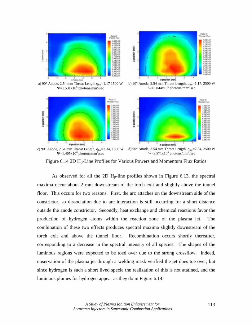
Figure 6.14 shows four 2D Hβ-line profiles for the 90°-sonic anode. From these
figures, the effects of torch power and momentum flux ratio on the plume shape and
maximum observed intensity could be determined. These plots identify three important
trends: changes in average rate of photon flux within the plasma jet, changes in the
maximum rate of photon flux, Ψ, and changes in the penetration height of the spectral
plume. The average rate of photon flux is defined as if the total intensity of the region
were spread evenly over the described area, in this case, 2 mm upstream, 4.5 mm
downstream, and 5 mm above the torch. In addition, the penetration height is defined as
the height at which the rate of photon flux within the jet drops below 2.0 x 10⁶
photons/mm2/sec. This level of photon flux is identified in each plot by a dashed
contour. Furthermore, each plot has a unique color scale that corresponds to the rate of
photon flux for various points within the plot. The flow is from left to right with the x-
position of 0 mm being the center of the torch exit.
A Study of Plasma Ignition Enhancement for Aeroramp Injectors in Supersonic Combustion Applications
113
a) 90° Anode, 2.54 mm Throat Length qbar=1.17 1500 W
Ψ=1.531x10⁶ photons/mm2/sec
b) 90° Anode, 2.54 mm Throat Length, qbar=1.17, 2500 W
Ψ=5.044x10⁶ photons/mm2/sec
c) 90° Anode, 2.54 mm Throat Length, qbar=2.34, 1500 W
Ψ=1.405x10⁶ photons/mm2/sec
d) 90° Anode, 2.54 mm Throat Length, qbar=2.34, 2500 W
Ψ=3.571x10⁶ photons/mm2/sec
Figure 6.14 2D Hβ-Line Profiles for Various Powers and Momentum Flux Ratios
As observed for all the 2D Hβ-line profiles shown in Figure 6.13, the spectral
maxima occur about 2 mm downstream of the torch exit and slightly above the tunnel
floor. This occurs for two reasons. First, the arc attaches on the downstream side of the
constrictor, so dissociation due to arc interaction is still occurring for a short distance
outside the anode constrictor. Secondly, heat exchange and chemical reactions favor the
production of hydrogen atoms within the reaction zone of the plasma jet. The
combination of these two effects produces spectral maxima slightly downstream of the
torch exit and above the tunnel floor. Recombination occurs shortly thereafter,
corresponding to a decrease in the spectral intensity of all species. The shapes of the
luminous regions were expected to be toed over due to the strong crossflow. Indeed,
observation of the plasma jet through a welding mask verified the jet does toe over, but
since hydrogen is such a short lived specie the realization of this is not attained, and the
luminous plumes for hydrogen appear as they do in Figure 6.14.

A Study of Plasma Ignition Enhancement for Aeroramp Injectors in Supersonic Combustion Applications
114
Expectedly, increases in power and decreases in feedstock mass flowrate were
both observed to cause an increase in the spectral intensity of the jet. Comparison of
6.14a and 6.14b show that increasing the power from 1500 to 2500 W increases the
average rate of photon flux by over 230%. Similarly, for the higher mass flowrate cases,
6.14c and 6.14d, the same increase in power only produces an increase in the average rate
of photon flux of 154%. The reason that the higher mass flowrate case shows less
increase is due to the addition of thermal mass from the feedstock. Higher flowrates than
those presented here would be expected to experience even less increase. In addition, the
maximum rates of photon flux increase by 169% for the low-flowrate case, and 238% for
the high-flowrate case. This agrees well with earlier trends and is caused by arc
constriction. High flowrates, which produce higher constrictor pressures, cause the arc to
constrict, thereby increasing the temperature of the arc core and the local production of
dissociated species. This is observed through the measurement of higher spectral
intensities at the exit of the jet, but as discussed earlier, the increase in thermal mass of
the feedstock gas causes a lower mean spectral intensity.
Comparison of the intensity contours in Figure 6.14 shows that only the power,
and not the flowrate, affects the penetration height of the hydrogen atoms. Increases in
power from 1500 to 2500 W exhibit a 1-mm increase in penetration height for both
feedstock flowrate cases from 3.5 mm to 4.5 mm. However, increases in the feedstock
flowrate produce no change in the penetration height of the excited hydrogen atoms. In
addition, the hot core identified by the red and yellow regions, does not always increase
in size or intensity with increasing flowrate. This observation, coupled with the fact that
power exhibits only slight influence on the penetration height, indicates that methods to
increase the penetration height should be found outside the plasma torch, such as an
aeroramp.
Figure 6.15 shows four centerline total temperature profiles, for which the
corresponding 2D profiles are shown in Figure 6.16. Four runs are presented here
ranging from 900 to 2800 W. As would be expected, increasing the torch power
produces a corresponding increase in the maximum measured total temperature, but
appears to have little affect on the penetration height. This was not an unexpected trend
as the penetration height is only a weak function of the stagnation temperature of the

A Study of Plasma Ignition Enhancement for Aeroramp Injectors in Supersonic Combustion Applications
115
feedstock gas (Chrans and Collins, 1970). As an item of interest, the 930-W profile was
produced during the 55th run of a molybdenum anode, a testimony to the durability of the
material.
Figure 6.15: Centerline Temperature Measurements for 90°, 2.54-mm Sonic Anode
The 2D temperature profiles shown in Figure 6.16 exhibit several important
trends involving the momentum flux ratio of the torch and torch input power. First, the
height of the plumes increases with increases in the momentum flux ratio for both the
1500 and 2500-W cases. However, the height of the plume core changes little with input
power and for both the 1500 and 2500-W cases. For a momentum flux ratio of 1.17, the
height of the core is located about three equivalent diameters, deq, above the tunnel floor
and slightly to the left of the torch centerline. (For a definition of deq refer to Appendix
C.) Increasing the momentum flux ratio to 2.34 increased the penetration height of the
core by one full diameter, for both 1500 and 2500 W, and brought the plume fully off the
floor.
Increases in the mass flowrate also caused a decrease in the maximum measured
total temperature ratios. For 1500 W, Figures 6.16a and 6.16c, doubling the momentum
flux ratio decreased the maximum total temperature ratio by 6%, from 1.26 to 1.19. The
2500-W cases also experienced this trend, although the difference was almost three times
larger at 16%, a drop from 1.68 to 1.42. This is not to imply that the energy imparted to
the feedstock gas by the arc under these conditions is less, but rather the measured value
of total temperature is less due to the addition of thermal mass. In fact, the total energy

A Study of Plasma Ignition Enhancement for Aeroramp Injectors in Supersonic Combustion Applications
116
may even be higher according to Equation 6.4, but the bulk temperature and average
spectral intensity are lower due to the added mass.
(a)
(b)
(c)
(d) Figure 6.16: 2D Temperature Profiles Comparing Power and Momentum Flux Ratio
Variations
Stereoscopic investigation of the 90° short-throat anode after testing confirmed
that the arc attachment point was located on the downstream side of the anode
constrictor, as shown in Figure 6.17 (flow is from left to right). Molten runoff (1), which
was present with other anodes, appears to propagate much further here than in other
experiments. A shallow cavity can be seen directly downstream of the constrictor (2),
which appears to be the source of the runoff and, because of its size and shape, indicates
the arc attachment point was not static during the testing. This cavity is bordered by a
shallow buildup of molybdenum (3), which is curved to conform to the outer edge of the
cavity. Also two minor cracks are present near the constrictor exit, evidence of thermal
loading of the material (4). Finally, a small spire of molybdenum can be seen on the
lower edge of the constrictor exit (5), formed by the rapid cooling of the molybdenum by
the crossflow.

A Study of Plasma Ignition Enhancement for Aeroramp Injectors in Supersonic Combustion Applications
117
1
2
3
4
5
Figure 6.17: Close-up Photograph of 90°, 2.34-mm Throat Length Sonic Anode
6.3.2.2: Results for the 90°, 3.12 mm Throat Length, Sonic Anode
Results for the 90°-sonic-long design are rather sparse because the stability of the
design was poor. Of the fourteen total attempted runs with this design, the torch either
failed to ignite, or extinguished shortly after ignition in six of them. In addition, after
several runs, it was impossible to operate the torch below 1500 W. The cause for this
poor operability is the extended throat length, for which a much higher voltage was
required to sustain the longer arc column. Since the cathode tips extends partially into
the anode constrictor, a 25% increase in the constrictor length from 2.54 to 3.12 mm
causes a theoretical increase of 48% in arc length. This increase is substantial and, in this
case, caused the operability of the design to be quite poor.
All of the spectroscopic data for this design has been presented in Figure 6.7,
where it was shown that the intensity of the Hβ line increased linearly with torch power.
The remainder of the available temperature data is shown below in Figure 6.18,
supplementing the data from Figure 6.10. Only high power cases are available since tests
involving lower powers were used to identify the plume centerline and then power had to
be increased to ensure operation. Runs from 2700 to 3400 W are shown and, as with the
short throat design, the penetration height is affected little by the torch input power. In
comparison to the temperature data in Figure 6.11, the penetration height of the 90°-
sonic-long design is around three deq, slightly below the 90°-sonic design, but well above
the 90° supersonic design.

A Study of Plasma Ignition Enhancement for Aeroramp Injectors in Supersonic Combustion Applications
118
Figure 6.18: Centerline Temperature Measurements for 90°, 3.12-mm Sonic Anode
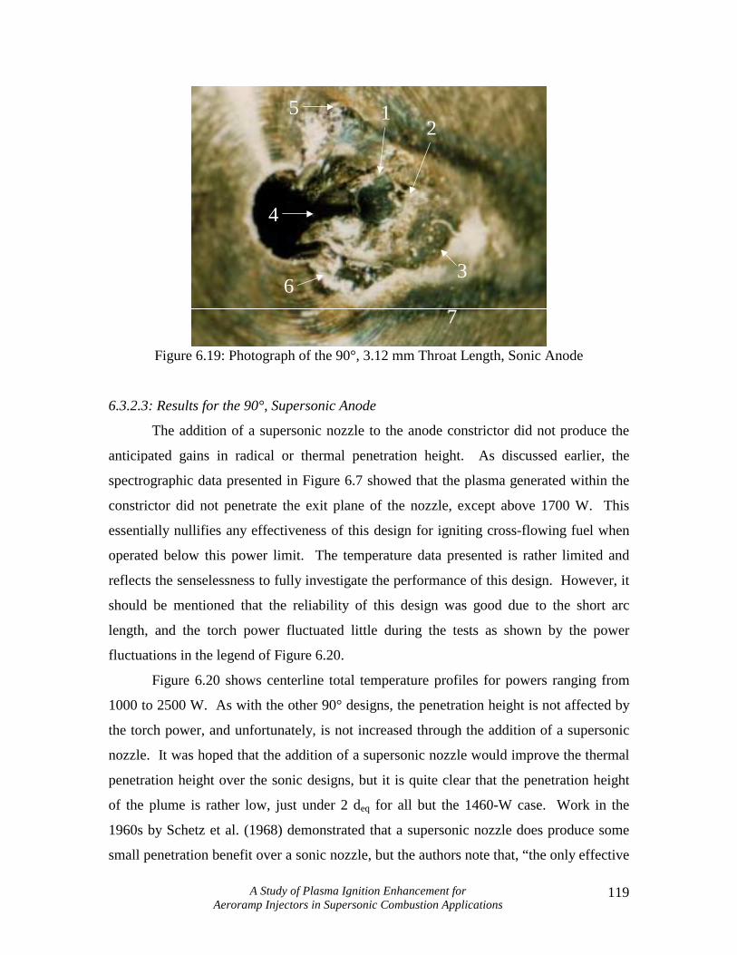
The stereoscopic investigation of the 90°-sonic-long anode showed features
similar to the short-throated counterpart. A close-up photograph of the anode is shown in
Figure 6.19 where flow is from left to right and with the line-of-sight originating slightly
upstream of the anode exit. As was found to be characteristic with normal injection
anodes, the arc attached solely on the downstream side of the constrictor, evidenced by a
large once-molten molybdenum bead (1). An area of buildup (2) has been formed
directly downstream of this region, creating a separation zone where soot deposits have
collected (3). The anode constrictor has been severely eroded on the downstream side,
more so than with the short-throat anode even though testing was shorter. This high level
of erosion is characterized by deep vertical channels (4), which have been cut away by
the arc, and formed as a result of the higher voltage necessary to sustain the arc. Also,
two short spires (5 and 6) border the eroded section of the anode throat, and seem to be
the center of two regions of light discoloration, characteristic of heat treatment removal.
Evidence of heat treatment removal is present downstream of the anode exit (7). Here the
heat treatment removal appears to be the cause of heat transfer from the plasma plume
due to the plume-like shape of the affected area.
A Study of Plasma Ignition Enhancement for Aeroramp Injectors in Supersonic Combustion Applications
119
2
36
5 1
7
4
Figure 6.19: Photograph of the 90°, 3.12 mm Throat Length, Sonic Anode
6.3.2.3: Results for the 90°, Supersonic Anode
The addition of a supersonic nozzle to the anode constrictor did not produce the
anticipated gains in radical or thermal penetration height. As discussed earlier, the
spectrographic data presented in Figure 6.7 showed that the plasma generated within the
constrictor did not penetrate the exit plane of the nozzle, except above 1700 W. This
essentially nullifies any effectiveness of this design for igniting cross-flowing fuel when
operated below this power limit. The temperature data presented is rather limited and
reflects the senselessness to fully investigate the performance of this design. However, it
should be mentioned that the reliability of this design was good due to the short arc
length, and the torch power fluctuated little during the tests as shown by the power
fluctuations in the legend of Figure 6.20.
Figure 6.20 shows centerline total temperature profiles for powers ranging from
1000 to 2500 W. As with the other 90° designs, the penetration height is not affected by
the torch power, and unfortunately, is not increased through the addition of a supersonic
nozzle. It was hoped that the addition of a supersonic nozzle would improve the thermal
penetration height over the sonic designs, but it is quite clear that the penetration height
of the plume is rather low, just under 2 deq for all but the 1460-W case. Work in the
1960s by Schetz et al. (1968) demonstrated that a supersonic nozzle does produce some
small penetration benefit over a sonic nozzle, but the authors note that, “the only effective

A Study of Plasma Ignition Enhancement for Aeroramp Injectors in Supersonic Combustion Applications
120
way of changing the penetration of a given amount of fluid through a round hole is by
changing the Mach number.” In the present case, it appears that the plasma negates, or
rather reverses these benefits. According to Rayleigh’s theory, a flow, whether subsonic
or supersonic, will approach Mach 1 as it is heated. The heating due to the presence of
the arc and plasma prevents the nozzle from producing supersonic flow at the exit plane.
On a positive note, this design does produce higher total temperature ratios compared to
the other two 90° designs. This is likely a result of poor mixing, but may also be
attributed to some limited combustion near the nozzle exit where the plasma and heated
methane interact with the air stream.
Figure 6.20: Centerline Temperature Measurements for the 90° Supersonic Design
Figure 6.21 shows a 2D total temperature ratio profile, and demonstrates the poor
penetration performance of this design. The plume essentially has been trapped on the
tunnel floor, with the plume core penetrating just under 2 deq, and the maximum height of
the plume just under 4 deq. It should be noted that total temperature plumes normally
produce symmetric profiles, but in this case a bad set of data at y/deq = 3 causes a peak to
occur, which normally would not be present. The core of the plume is oriented along the
centerline of the torch indicating that the swirl has had no affect in pushing the plume off
to either side. It is clear then, both from the temperature data, and more specifically the
spectral data, that the addition of a supersonic diverging nozzle to a normally oriented
anode serves only to decrease the amount of energy available for the ignition of fuel. In

A Study of Plasma Ignition Enhancement for Aeroramp Injectors in Supersonic Combustion Applications
121
addition, the penetration height of this energy is reduced as well, evidenced by the
downstream temperature probing.
Figure 6.21: 2D Temperature Profile for the 90° Supersonic Design
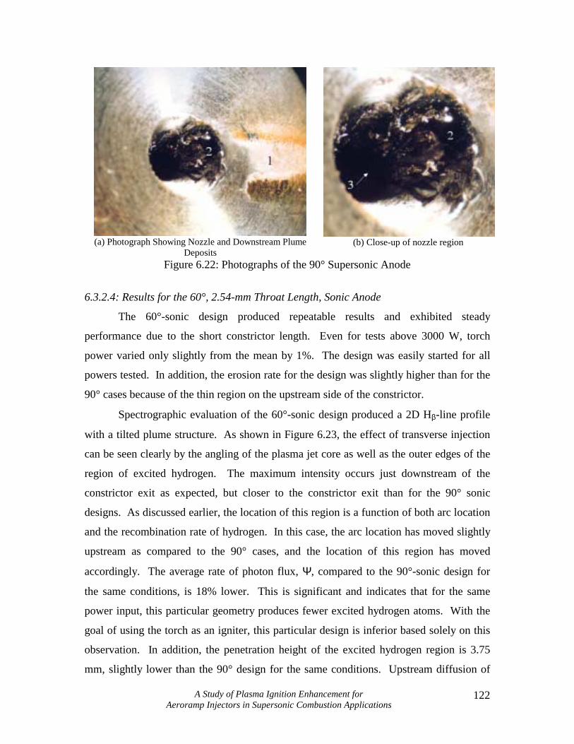
Two photographs were taken of the 90° supersonic anode after testing and are
shown in Figure 6.22, with flow from left to right. Analysis of the anode through the
stereoscope showed that quite a bit of erosion of the anode had taken place, producing the
broad, uneven flows seen in the nozzle. The pictures are somewhat misleading; the
thickness of these flows is rather shallow. However, the important point to mention here
is that, in regards to a supersonic nozzle, any amount of erosion destroys the flowfield of
the nozzle, negating the purpose for which it was intended. In Figure 6.22a, the angle of
view from slightly upstream so that the nozzle and deposits left by the plume can both be
seen. The yellow-orange regions downstream of the nozzle (1) are deposits left by the
plasma jet and are not caused by heat treatment removal. The center of the plume is
white in color mixed with some orange, and then transitions to yellow on the outer edges.
It is believed that these deposits are the result of compressor oil from the tunnel
compressor being swept downstream into the plasma jet and then burned. Figure 6.22b is
a close-up of the nozzle and shows a complex flow pattern of the molybdenum that has
been melted and swept through the nozzle (2). The arc attachment point appears to be at
the border of the throat and nozzle since the flows originate from this point (3). In
addition, the flows have a blackened appearance caused by the close proximity of the
methane plasma jet.
A Study of Plasma Ignition Enhancement for Aeroramp Injectors in Supersonic Combustion Applications
122
(a) Photograph Showing Nozzle and Downstream Plume
Deposits (b) Close-up of nozzle region
Figure 6.22: Photographs of the 90° Supersonic Anode
6.3.2.4: Results for the 60°, 2.54-mm Throat Length, Sonic Anode
The 60°-sonic design produced repeatable results and exhibited steady
performance due to the short constrictor length. Even for tests above 3000 W, torch
power varied only slightly from the mean by 1%. The design was easily started for all
powers tested. In addition, the erosion rate for the design was slightly higher than for the
90° cases because of the thin region on the upstream side of the constrictor.
Spectrographic evaluation of the 60°-sonic design produced a 2D Hβ-line profile
with a tilted plume structure. As shown in Figure 6.23, the effect of transverse injection
can be seen clearly by the angling of the plasma jet core as well as the outer edges of the
region of excited hydrogen. The maximum intensity occurs just downstream of the
constrictor exit as expected, but closer to the constrictor exit than for the 90° sonic
designs. As discussed earlier, the location of this region is a function of both arc location
and the recombination rate of hydrogen. In this case, the arc location has moved slightly
upstream as compared to the 90° cases, and the location of this region has moved
accordingly. The average rate of photon flux, Ψ, compared to the 90°-sonic design for
the same conditions, is 18% lower. This is significant and indicates that for the same
power input, this particular geometry produces fewer excited hydrogen atoms. With the
goal of using the torch as an igniter, this particular design is inferior based solely on this
observation. In addition, the penetration height of the excited hydrogen region is 3.75
mm, slightly lower than the 90° design for the same conditions. Upstream diffusion of

A Study of Plasma Ignition Enhancement for Aeroramp Injectors in Supersonic Combustion Applications
123
excited hydrogen atoms into the separation zone persists for almost 3 mm, caused by
erosion of the thin, upstream portion of the constrictor exit.
Ψ=1.252x10⁶ photons/mm2/sec
Figure 6.23: 2D Hβ-Line Profile for 60°, 2.34-mm Throat Length Anode (qbar=1.17, 1500 W)
Figure 6.24 shows centerline temperature measurements for five runs ranging
from 1100 to 3400 W. Although the penetration height of this design was generally
poorer than for the 90° designs, this trend worsens for lower powers. The penetration
height is well below 1 deq for the 1100-W case, and increases slightly to 2 deq for 1530 W.
Penetration height for powers above this limit changes little until 3400 W when the
penetration height increases slightly to just above 2 deq.
Figure 6.24: Centerline Temperature Measurements for the 60°, 2.54-mm Sonic Anode
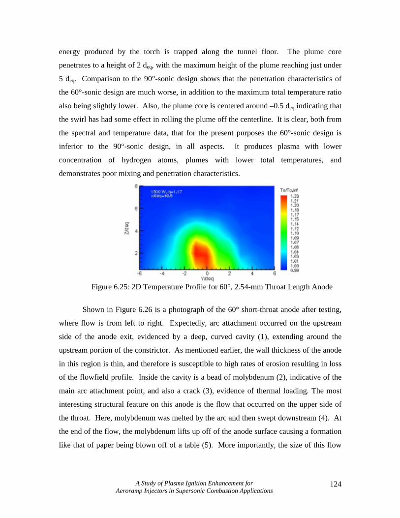
A 2D total temperature plot is shown in Figure 6.25 for a torch input power of
1500 W and a momentum flux ratio of 1.17. It is clear from this plot that the thermal
A Study of Plasma Ignition Enhancement for Aeroramp Injectors in Supersonic Combustion Applications
124
energy produced by the torch is trapped along the tunnel floor. The plume core
penetrates to a height of 2 deq, with the maximum height of the plume reaching just under
5 deq. Comparison to the 90°-sonic design shows that the penetration characteristics of
the 60°-sonic design are much worse, in addition to the maximum total temperature ratio
also being slightly lower. Also, the plume core is centered around –0.5 deq indicating that
the swirl has had some effect in rolling the plume off the centerline. It is clear, both from
the spectral and temperature data, that for the present purposes the 60°-sonic design is
inferior to the 90°-sonic design, in all aspects. It produces plasma with lower
concentration of hydrogen atoms, plumes with lower total temperatures, and
demonstrates poor mixing and penetration characteristics.
Figure 6.25: 2D Temperature Profile for 60°, 2.54-mm Throat Length Anode
Shown in Figure 6.26 is a photograph of the 60° short-throat anode after testing,
where flow is from left to right. Expectedly, arc attachment occurred on the upstream
side of the anode exit, evidenced by a deep, curved cavity (1), extending around the
upstream portion of the constrictor. As mentioned earlier, the wall thickness of the anode
in this region is thin, and therefore is susceptible to high rates of erosion resulting in loss
of the flowfield profile. Inside the cavity is a bead of molybdenum (2), indicative of the
main arc attachment point, and also a crack (3), evidence of thermal loading. The most
interesting structural feature on this anode is the flow that occurred on the upper side of
the throat. Here, molybdenum was melted by the arc and then swept downstream (4). At
the end of the flow, the molybdenum lifts up off of the anode surface causing a formation
like that of paper being blown off of a table (5). More importantly, the size of this flow

A Study of Plasma Ignition Enhancement for Aeroramp Injectors in Supersonic Combustion Applications
125
more clearly indicates the amount of material removed from the upstream portion of the
constrictor.
Figure 6.26: Anode Wear on the 60°, 2.54-mm Throat Length, Sonic Anode
6.3.2.5: Results for the 60°, 3.12 mm Throat Length, Sonic Anode
Despite the increased throat length, the 60°-sonic-long design was quite stable,
and did not suffer from starting problems like those experienced with the 90°-sonic-long
design. The repeatability and stability of performance allowed in-depth study of the
design on a spectroscopic and thermal basis. Spectrographic and temperature
measurements were taken for various powers and momentum flux ratios to provide a
means of evaluating how the design operated under various conditions.
Spectrographic evaluation of the 60°-sonic-long design showed that increasing the
momentum flux ratio of the torch lowered the spectral intensity of the Hβ line through the
power range of interest. The data shown in Figure 6.27 represent a similar trend as with
the 90°-sonic-short design in Figure 6.13, except that the two linear models do not
intersect. For a given rate of photon flux, the increased power requirement for the high
momentum flux ratio case can be attributed to the constriction of the arc. With the rate of
photon flux plotted against current, the trend lines are closer, but still distinctly separate,
indicating that the arc geometry also affects the rate of excited hydrogen production.
The x-intercept of the trend line corresponds to the point at which radical production is

A Study of Plasma Ignition Enhancement for Aeroramp Injectors in Supersonic Combustion Applications
126
zero, or more accurately, the theoretical power limit below which torch operation is
prohibited with the present power supply configuration. Extrapolation of the trend lines
show that the lower momentum flux ratio trend line intersects the x-axis at 1250 W, while
for the higher momentum flux ratio, the intercept is 1400 W. For the given flowrates, the
torch could not be started below these limits, verifying that spectroscopic analysis of the
plasma jet could be used to determine the theoretical limit below which an arc cannot be
sustained.
0.00E+00
5.00E+06
1.00E+07
1.50E+07
2.00E+07
2.50E+07
3.00E+07
3.50E+07
1000 1500 2000 2500 3000 3500 4000 4500 5000Torch Pow er (W)
Rate
of P
hoto
n Fl
ux (P
hoto
ns/m
m2/
sec)
q=1.17
q=2.34
Figure 6.27: Comparison of Exit Profiles for Different Momentum Flux Ratios
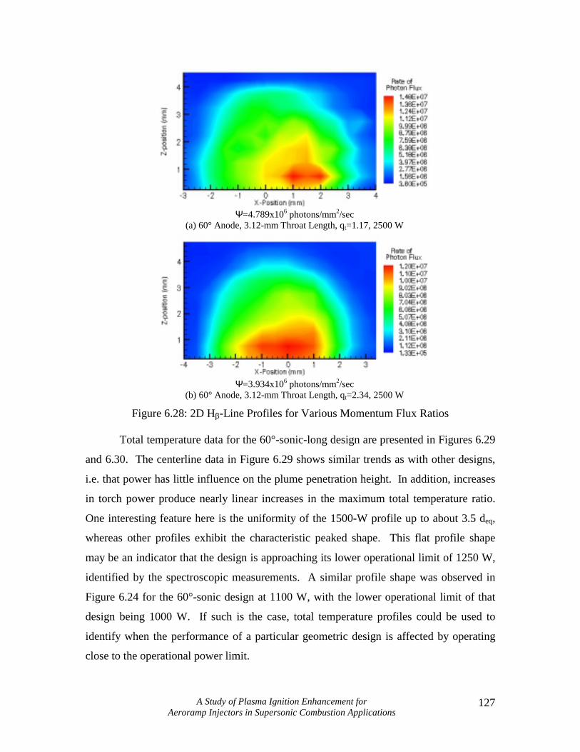
Two 2D Hβ-line intensity profiles are presented in Figure 6.28 for 2500 W and
two momentum flux ratios. The plumes produced for this design exhibit characteristics
of both the 60° and 90°-sonic designs. The region of excited hydrogen exhibits much the
same overall shape as for the 90°-sonic design, but retains the characteristic tilted core
observed with the 60°-sonic design. In addition, the upstream diffusion of excited
hydrogen atoms is still evident, caused by the erosion of the upstream portion of the
anode constrictor. Also, the region of maximum intensity is still closely oriented to the
constrictor exit, caused by the location of the arc attachment point. The increased mass
flowrate decreased both the maximum and average rates of photon flux by 18%. As with
the spectroscopic studies for the other designs, the penetration height does not seem to be
affected by the feedstock flowrate. Only the plume intensity showed dependence on
feedstock flowrate.
A Study of Plasma Ignition Enhancement for Aeroramp Injectors in Supersonic Combustion Applications
127
Ψ=4.789x10⁶ photons/mm2/sec
(a) 60° Anode, 3.12-mm Throat Length, qt=1.17, 2500 W
Ψ=3.934x10⁶ photons/mm2/sec
(b) 60° Anode, 3.12-mm Throat Length, qt=2.34, 2500 W
Figure 6.28: 2D Hβ-Line Profiles for Various Momentum Flux Ratios
Total temperature data for the 60°-sonic-long design are presented in Figures 6.29
and 6.30. The centerline data in Figure 6.29 shows similar trends as with other designs,
i.e. that power has little influence on the plume penetration height. In addition, increases
in torch power produce nearly linear increases in the maximum total temperature ratio.
One interesting feature here is the uniformity of the 1500-W profile up to about 3.5 deq,
whereas other profiles exhibit the characteristic peaked shape. This flat profile shape
may be an indicator that the design is approaching its lower operational limit of 1250 W,
identified by the spectroscopic measurements. A similar profile shape was observed in
Figure 6.24 for the 60°-sonic design at 1100 W, with the lower operational limit of that
design being 1000 W. If such is the case, total temperature profiles could be used to
identify when the performance of a particular geometric design is affected by operating
close to the operational power limit.

A Study of Plasma Ignition Enhancement for Aeroramp Injectors in Supersonic Combustion Applications
128
Figure 6.29: Centerline Temperature Measurements for 60° Sonic Long Throat
The 2D temperature profiles in Figure 6.30 demonstrate how changes in
momentum flux ratio and torch power affect the downstream plume of the torch.
Generally, the temperature profiles produced by this design exhibited good penetration
and a symmetric shape, except for the profile shown in Figure 6.30a, where a region of
higher temperature gas has formed due to a small flame plume emanating out the side of
the torch exit. Increasing the momentum flux ratio of the torch from 1.17 to 2.34 doubled
the penetration height of the plume core from 2 deq to 4 deq. For the same conditions, the
penetration height of the 90°-sonic design was slightly better at 2.5 deq and 4.5 deq
respectively. Comparison of Figures 6.30a and 6.30b shows a 16% decrease in the
maximum total temperature ratio for the higher momentum flux ratio caused by the
increase in thermal mass of the feedstock. The swirl of the plasma jet has caused a slight
shift of the plume centerline to the left of the centerline of the torch, more so for the
lower momentum flux ratio case. Increasing the power from 2500 to 3500 W caused a
35% increase in the maximum total temperature ratio, but did not increase the height of
the plume core. In Figure 6.30c, the plume core is directly aligned with the centerline of
the torch, but closer inspection reveals that the outer edges of the core extend farther to
the left than to the right, evidence that the swirl produced by the torch still has an effect,
even at higher powers.

A Study of Plasma Ignition Enhancement for Aeroramp Injectors in Supersonic Combustion Applications
129
(a) 2500 W, qt=1.17
(b) 2500 W, qt=2.34
(c) 3500 W, qt=2.34
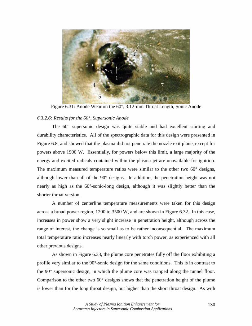
Figure 6.30: 2D Temperature Profiles of the 60°, 3.12-mm, Sonic Throat Anode Analysis of the anode surface after testing showed that the arc attached on the
right side of the anode constrictor, rather than on the upstream side, as was expected. As
shown in Figure 6.31, the anode loss (1) is characterized by a deep, narrow channel, cut
into the right side of the anode constrictor by the arc. Directly downstream of the
channel is a large spire (2) formed from the displaced molybdenum. Also evidence of arc
attachment exists on the upstream side of the anode where part of the constrictor has been
eroded away (3). A shallow cavity (4) is present adjacent to this region. As with the
main cavity on the right side of the constrictor, a small spire has formed downstream (5).
In addition to these features, there is also a small, golden-colored bead directly upstream
of the anode constrictor (6), which does not seem to be discolored due to heat treatment
removal. Finally, a soot trail left by the plasma jet (7), originating mainly from the left
side of the constrictor, discolors the anode surface. The swirl induced by the flow
swirler, and the presence of the arc on the right side of the constrictor acting as an
obstruction, both contributed to pushing the plume out of the left side of the constrictor
exit. The downstream evidence of this was shown in Figures 6.28a and 6.28b, where the
centerline of the plume is just to the left of the torch exit centerline.
A Study of Plasma Ignition Enhancement for Aeroramp Injectors in Supersonic Combustion Applications
130
7
36
2
1
5
4
Figure 6.31: Anode Wear on the 60°, 3.12-mm Throat Length, Sonic Anode
6.3.2.6: Results for the 60°, Supersonic Anode
The 60° supersonic design was quite stable and had excellent starting and
durability characteristics. All of the spectrographic data for this design were presented in
Figure 6.8, and showed that the plasma did not penetrate the nozzle exit plane, except for
powers above 1900 W. Essentially, for powers below this limit, a large majority of the
energy and excited radicals contained within the plasma jet are unavailable for ignition.
The maximum measured temperature ratios were similar to the other two 60° designs,
although lower than all of the 90° designs. In addition, the penetration height was not
nearly as high as the 60°-sonic-long design, although it was slightly better than the
shorter throat version.
A number of centerline temperature measurements were taken for this design
across a broad power region, 1200 to 3500 W, and are shown in Figure 6.32. In this case,
increases in power show a very slight increase in penetration height, although across the
range of interest, the change is so small as to be rather inconsequential. The maximum
total temperature ratio increases nearly linearly with torch power, as experienced with all
other previous designs.
As shown in Figure 6.33, the plume core penetrates fully off the floor exhibiting a
profile very similar to the 90°-sonic design for the same conditions. This is in contrast to
the 90° supersonic design, in which the plume core was trapped along the tunnel floor.
Comparison to the other two 60° designs shows that the penetration height of the plume
is lower than for the long throat design, but higher than the short throat design. As with

A Study of Plasma Ignition Enhancement for Aeroramp Injectors in Supersonic Combustion Applications
131
the 90° supersonic nozzle, it appears that the nozzle here has little, if any, effect on the
penetration height of the feedstock gas. The maximum total temperature ratio here is
slightly lower than in the 90° supersonic case, a difference of 1.31 to 1.23, and can
probably be attributed the amount of mixing rather than any indication of decreased
energy content within the plume. As with the other 60° designs, swirl effects are evident
by the slight spread of the plume edge to the left, although the centerline of the plume
remains along the centerline of the plasma torch.
Figure 6.32: Centerline Total Temperature Measurements for the 60° Supersonic Anode
Figure 6.33: 2D Temperature Profile for 60° Supersonic Anode
In comparison to the other stereoscopic investigations, the 60° supersonic anode
produced perhaps the most interesting features of all. Figure 6.34a shows the nozzle
region and a lightly colored soot trail (1) from the plasma jet, where flow is from left to
right. All of the anode wear originates on the downstream side of the anode constrictor,

A Study of Plasma Ignition Enhancement for Aeroramp Injectors in Supersonic Combustion Applications
132
as evidenced by a large, lustrous flow (2). This flow appears dark because of the viewing
angle, and originates at the anode constrictor exit plane. Heat flux from the arc melted
the molybdenum near the constrictor exit, which was then pushed up along the surface of
the nozzle by convection, forming the flow. The flow lifts off of the nozzle surface near
the end of its travel, evidenced by the shadow of the flow (3) on the surface of the nozzle.
The volume of the flow appears to be much greater than any present anode wear.
Analysis of the interior and exterior anode surfaces showed little surface damage,
indicating that this flow may be made up of low-density molybdenum crystals. The
formation of this flow certainly affected the penetration characteristics of the nozzle,
which was the same problem encountered with the 90° supersonic design. That is, any
type of anode wear will cause degradation in the flowfield within the nozzle, negating the
purpose for which it was intended. In addition to this feature, there is also some evidence
of arc attachment to the left (4) and right (5) of the main flow causing two smaller flows
of molybdenum.
(a) The Nozzle and Anode Surface
(b) Close-up of Nozzle Region
Figure 6.34: Close-up Photograph of 60°, Supersonic Anode
6.4: Conclusions
This chapter presented the results of two separate geometric studies of the plasma
torch anode, intended to investigate geometric features that could be altered to enhance
the ignition capability of a plasma torch. The first study investigated the effects of
altering the half-angle of the diverging section of the anode. The purpose of the study
was to determine the effect of the half-angle on the power requirements for the torch, and

A Study of Plasma Ignition Enhancement for Aeroramp Injectors in Supersonic Combustion Applications
133
also to determine if the diverging section was necessary to protect the arc from a
supersonic crossflow. For constant current and flowrate, the studies showed that the
commonly used half-angle of 45° was the worst design, requiring more power to operate
than any of the other four designs. In other applications, this may actually be a benefit, as
higher powers can be imparted to an arc for a shorter constrictor length. However, in this
application, it is important to maximize the efficiency of the design by reducing the
required power input and maintaining the performance. The anode with no diverging
section produced lower powers, both for methane and argon feedstocks. This power
difference was attributed to a combination of the amount of arc turning, which induces a
higher voltage gradient than a straight arc, and an electric field concentration due to the
constrictor exit geometry. In addition, supersonic experiments demonstrated that the
diverging section was not needed to protect the arc from a supersonic crossflow. Given
these two observations, it was concluded that for igniting a cross-flowing fuel-air
mixture, the diverging section should be removed, both because of the lower power
requirements of the design, and the elimination of the region inside the diverging section
where recombination occurs, which essentially wastes the energy otherwise available for
ignition.
The second study investigated the effects of throat length, injection angle, and the
addition of supersonic nozzles to the anode constrictor. These tests were conducted in a
Mach 2.4 crossflow with methane as the feedstock. Spectrographic and total temperature
measurements were used to evaluate the performance of each design, while stereoscopic
investigations were used to assess the erosion characteristics of the different geometries.
In general, increasing the throat length increased the maximum total temperature of the
downstream plume, and the intensity of the Hβ-line profiles due to the longer arc length.
However, in the case of the 90° design, the longer throat length was observed to severely
affect the stability of the design. The addition of supersonic nozzles were expected to
increase the penetration height of the design, but in actuality hampered the performance
of the torch by providing a region in which the plasma could recombine without
interacting with the fuel. Only above 1800 W was the plasma observed to penetrate the
exit plane of the nozzle, and even then, the intensity of radiation emitted by the excited
hydrogen atoms within the jet was much lower than for any of the other designs. In
A Study of Plasma Ignition Enhancement for Aeroramp Injectors in Supersonic Combustion Applications
134
addition, the anticipated penetration benefits were never realized since the flowfield
within the nozzle was disrupted by anode erosion. Finally, the injection angle was found
to have a strong influence on penetration height, downstream maximum total temperature
measurements, and the intensity of the Hβ-line intensity profiles. Anodes designed for
transverse injection produced jets with lower overall intensities for excited hydrogen, and
plumes with lower total temperature. Although neither method can be used to
quantitatively ascertain the energy content within the plasma, the combination of these
two effects can imply that the energy imparted to the feedstock gas is less with an anode
designed for transverse injection. This was attributed to the stationary nature of the arc,
which in almost all cases, attached on the upstream portion of the anode constrictor.
Finally, it was theorized that spectrographic methods could be used to evaluate
the stability and lower operational limit of different anode designs. Exit Hβ-line profiles
showed that the increase in the intensity of the Hβ line was linearly proportional to the
torch input power. The slope of this function is thought to be an indicator of stability,
with lower slopes indicating a more stable design. Observation of the torch during
testing supports this theory. The x-intercept, where the linear trend line intersects the
power axis, indicates the point at which radical production is zero, and theoretically, the
point at which operation of the torch below this limit is impossible. Given the power
supply configuration, the designs were incapable of operating below these theoretical
limits, substantiating the theory.
In general, these studies were vital for providing a fundamental understanding of
how changes in the anode geometry affect torch performance, but also to provide a basis
for choosing a design for future work. Based on the measurements and observations
made during the two-part experimental study of anode geometry, the normal injection,
2.54-mm throat length anode (90°-sonic) was chosen as the design with which to perform
all future experiments. This decision was based on the performance of the design
compared to the other five on both a spectral and thermal basis. For a given power and
feedstock flowrate, the 90°-sonic design exhibited superior penetration characteristics,
and produced plasma jets with higher overall spectral intensities for the Hβ line. In
addition, the design possesses excellent stability characteristics, and can operate over a
wide power range.