Embed Size (px)
Citation preview

Chapter 6Efficient and Deadlock-Free Tree-BasedMulticast Routing Methodsfor Networks-on-Chip (NoC)
Faizal Arya Samman and Thomas Hollstein
Abstract This chapter presents a new efficient and deadlock free tree-basedmulticast routing method and concept. The presented deadlock-free multicastrouting algorithm can be implemented on a network-on-chip (NoC) router microar-chitecture, realizing a mesh planar network topology. The NoC microarchitecturesupports both deadlock-free static and efficient adaptive tree-based multicast rout-ing. Multicast packets are routed and scheduled in the NoC by using a flexiblemultiplexing/interleaving technique with wormhole switching. The flexibility of theproposed multicast routing method is based on a locally managed packet identity(ID-tag) attached to every flit. This concept allows different packets to be interleavedat flit-level in a single buffer pool on the same link. Furthermore, a pheromonetracking strategy presented in this chapter, which is used to reduce communicationenergy in the adaptive tree-based multicast routing method. The strategy is used toperform efficient spanning trees for the adaptive tree-based multicast routing whichare generated at runtime.
6.1 Introduction
Recent multicomputers and large-scale multiprocessor systems have been developedtowards collective communication services to reduce communication overheads ofparallel computations running on these systems. These collective communication
F.A. Samman (�)Universitas Hasanuddin, Fakultas Teknik, Jurusan Teknik Elektro,Jl. Perintis Kemerdekaan Km. 10, Makassar 90245, Indonesiae-mail: [email protected]
T. HollsteinDepartment of Computer Engineering, Tallinn University of Technology,Akadeemia tee 15A, 12618 Tallinn, Estoniae-mail: [email protected]
M. Palesi and M. Daneshtalab (eds.), Routing Algorithms in Networks-on-Chip,DOI 10.1007/978-1-4614-8274-1__6, © Springer Science+Business Media New York 2014
129
130 F.A. Samman and T. Hollstein
services include one-to-many communication such as multicast (the same messageis sent from one source node to an arbitrary number of destination nodes), one-to-all communication such as broadcast (the same message is sent from one sourcenode to all nodes (entries) in the network) and scatter (different messages are sentfrom one source node to all entries in the network), many-to-one communication(one destination node receives different messages from an arbitrary number ofsource nodes), and all-to-one communication such as reduce (one destinationnode combines different messages from an arbitrary number of source nodes byperforming a certain operation such addition, multiplication, maximum, minimum,or a logical operation).
Among the aforementioned collective communications, multicast and broadcastcommunications are the most interesting communication modes. Both communica-tion modes are needed in many parallel algorithms and applications in multipro-cessor systems. They also require special attention and handling in the networkcommunication protocol layers. A processing node in a multiprocessor system caninject a multicast message into a network by sending separate individual copies ofthe message from the source to every destination node. However, this unicast-basedmulticast delivery is energy- and time-consuming [24].
In large-scale off-chip multiprocessor systems, collective communication ser-vices, such as multicast communication, have been a fundamental prerequisite forsome data parallel computer languages. In a distributed shared-memory (DSM)parallel programming model, the multicast data communication service is appliedto efficiently support shared-data invalidation and updating on distributed nodes.This is being used in numerous parallel algorithms, e.g. parallel search and parallelgraph algorithms. In a single-program multiple-data (SPMD) and in a data parallelprogramming models, a variety of process control operations and global datamovements such as reduction, replication, permutation, segmented scan and barriersynchronization [16] can benefit from multicast services.
In the Multiprocessor System-on-Chip (MPSoC) or multicores systems do-mains, parallel computing problems can potentially be solved based on parallelprogramming models. Therefore, multicast communication services, which shouldbe implemented in upper protocol layers (typically on software level) and bottomprotocol layers (typically on hardware level), will also be an important issuein a NoC-based multiprocessor context. Modern 3D chip stacking technologiesenable on-Chip DSM systems with local DRAM memory being available at everyprocessing node. Multicast communication services are in this context essential forefficient implementation of memory coherency protocols. Furthermore, in the upperprotocol layers, multicast services are implemented as Application ProgrammingInterface (API) routines (programming model) that can be used by users to developparallel computing programs.
Further information on multicast routing issues can be found in [10]. Thischapter is addressing a router hardware architecture supporting an efficient tree-based adaptive multicast routing method for NoCs that is implemented in bottomcommunication network protocol layers, i.e. on network, data link and physicallayers according to the Open Systems Interconnection (OSI) model [30].

6 Efficient and Deadlock-Free Multicast Routing Method for NoCs 131
6.2 Occurrence of a Deadlock Problem Dueto Multicast Dependency
This chapter describes the use of an efficient multicast routing method for NoCs.However, the use of the tree-based multicast routing method may lead to a multicastdependency problem ending up in a deadlock, as presented in Fig. 6.1. Thismulticast dependency can cause a multicast deadlock configuration (as describedin Duato’s Book [10]). In this case, multicast packets block each other and cannotmove further.
The deadlock problem occurs especially if packets switched with the wormholemethod or virtual cut-through switching are not short enough, there is not enoughbuffer space to store the contenting wormhole packet, and/or arbitration rules arenot well organized to handle the multicast contention. In node (2,2) as presented inthe figure, packet A blocks the flow of two multicast branches of packet B (to westand east), while in node (2,1), packet B blocks the flow of two multicast branches ofpacket A (to west and to east). Due to the “wait and hold” situation in both networkswitch nodes, both message A and B cannot move further.
In this chapter a NoC architecture called XHiNoC (eXtendable HierarchicalNetwork-on-Chip) is presented, which proposes a novel wormhole cut-throughswitching concept [26] based on a local identity-based (ID-based) interleavedrouting organization, in which the ID-tag of each packet is locally updated oneach communication link [23]. The XHiNoC’s concept has also exhibited a novelmulticast routing method [22, 24, 25] for NoCs based on the interleaved routingorganization with local Identity (ID) management. In the XHiNoC routers, the justdescribed deadlock configuration problem (due to multicast dependencies) is solvedefficiently by using a so-called “hold and release tagging mechanism”.
input portoutput port
(1,2) (2,2) (3,2)
(1,1) (2,1) (3,1)
Packet A
Packet B
Fig. 6.1 Deadlock configuration in tree-based multicast routing

132 F.A. Samman and T. Hollstein
The hold-release tagging mechanism is based on an asynchronous data switchingapproach. A multicast flit will not be switched to an outgoing port, before itsmulticast request has been granted by the arbiter unit at the considered outgoingport. Each individual request can be granted asynchronously. Once the individualrequest is granted, it will be switched out towards the next link. The Hold-ReleaseTagging Mechanism applies the following principle to escape from flit contentiondue to multicast dependency. “If a multicast flit from an input port n has an numberN of requests at time ts, then each single request to an output port m can beforwarded from the input port n to this output port m in the next time stage ifand only if it receives a grant by an arbitration unit at the input port n, while theother requests must be held in the input port if they did not receive a grant by theirrequested output ports. In each next time stage, a single request, which has beengranted before, must be reset to prevent improper flit replication. If all requestshave been granted, then the multicast flit can be released from the queue in inputport n [25]”.
Most of this chapter contents are adopted from our paper published by ElsevierScience [27]. Therefore, we would like to thank Elsevier Science for the Cour-tesy/Permission to republish some parts of the issue.
6.3 ID-Based Routing Organization
In the XHiNoC routing concept, an ID-tag is attached on each flit of a datapacket. Flits belonging to the same data packet will have the same local ID-tagon each communication link. Based on this concept, multicast communicationscan be handled dynamically and pre-processing algorithms are not required beforeinjecting multicast messages.
6.3.1 ID-Based Multiple Access (IDMA) PacketStream Interleaving
Figure 6.2 illustrates, how five packets or data streams (a,b,c,d and e) can beinterleaved on each communication link. For instance, the ID-tag allocation of thestream a sent from Sw4 to Sw3 via Sw5 and Sw2 can be seen. Its ID-tags are mappedand allocated to ID slot 2 on Local input link of Sw4, ID slot 1 on West input link ofSw5, ID slot 1 on North1 input link of Sw2, ID slot 1 on West input link of Sw3 andat last, to ID slot 0 on Local output link of Sw3. Flits belonging to the same packet orstream will have the same ID-tag on a specific link. Therefore, the ID-tag attachedon every flit enables each packet or streaming data flit to be switched to the correctrouted direction. In other words, the ID-tag represents the compressed form of therouting direction made by the header flit when reserving communication resources.

6 Efficient and Deadlock-Free Multicast Routing Method for NoCs 133
e
ba
cd
021
01
30 1
1
1 0
1
2
0
0 0
2
3
21
ab c d
e
Sw1 Sw2 Sw3
Sw4 Sw5 Sw6
3
Fig. 6.2 ID-tag-based routing/switching organization and connection scheduling
Each streaming data flit can extract the required routing direction from the routingtable that has been indexed in accordance with the local ID-tag of the packet stream.
6.3.2 Routing Table and ID Management
The local ID-tag attached on each flit of the packet (see Fig. 6.5) is updated anddynamically changed once a flit is switched to a new outgoing port. The ID updateis made by an ID management unit located at every output port. Figure 6.2 shows thedetailed view of the link sharing between stream a, b and c as presented in Fig. 6.2.The communication resource (link) connecting South1 output port of Switch 5(Sw5) and North1 input port of Switch 2 (Sw2) assigns packet stream a, b and c withID-tag 1, 0 and 2, respectively. Tables presented on the right side of the switches arethe ID-slot table of the South1 output port at Sw5 and the routing table (LUT) ofthe North1 input port at Sw2. The content of the ID-slot table represents the ID-tagmapping function of each packet stream. The content of the routing table representsthe routing directions to keep the correct routing tracks for each flit of the interleavedpacket streams.
Figure 6.2 shows how the ID-tag of a stream header coming from NORTH portwith ID-tag 3 is updated after being switched. The ID update process working asfollows: When the IDM detects a new incoming stream or packet header, thenit searches for a free ID slot on the output link by checking the ID-slot state inthe corresponding table. In the example case, the ID-tag 2 is free. The ID is thenassigned as the new ID-tag on the next link segment. The ID-slot 2 is indexed basedon the associated incoming local ID-tag 3 and the incoming direction (NORTH).Hence, a data flit following the packet/stream at any instant time coming fromNORTH port with ID-tag 3 will be assigned also with the new ID-tag 2 in theoutgoing SOUTH port. In the same phase, the ID-tag 2 flag is set from “free” to“used” state, and the number of used IDs (UID) is incremented. When the UID has

134 F.A. Samman and T. Hollstein
id E S1 L
M
0123
11
1
1
1
1
1 02
2
3
Sw2
00
ID slot table on Sw5of South1 port
local
north1west
oldid
10 1
13
fromport
newid
2
M
Sw5
Routing Table on Sw2of North1 port
Fig. 6.3 IDMA: packet flit (wire-through-share) interleaving
Head 3 word
idstateused
freefree
free
used
idslot
123
0
M
Head 2 word
A
local
north1west
oldid
M
3
10 1
13
fromport
newid
2set toused
search forfree id slot
nid=2
0
0Number of usedid−tag (nid) isset from 2 to 3
Fig. 6.4 IDMA: ID-tagupdating
reached the number N of available ID slots, then “empty free ID flag” is set. Whena tail flit (the end of stream data) is passing through the outgoing port, then the stateof the related ID-tag 2 state is set from “used” to “free”, the UID is decrementedand the information related to this ID-number is then deleted from the ID Slot Tableconcurrently (Figs. 6.3 and 6.4).
More information about the dynamic ID management can be found in detail in[22–24, 26].
6 Efficient and Deadlock-Free Multicast Routing Method for NoCs 135
Payload Data
Ext.Source Addr.
DBody
Tail
ID−tag
DBody
Head
Head Source Addr.
Source Addr.
Target Addr. 2
Target Addr. 1
Ext.
Ext.
ID−tag
ID−tag
ID−tag
ID−tag
ID−tag
Payload Data
Type ID field Data Word
Head
Target Addr. Nhf
Probably Data or a Control Message
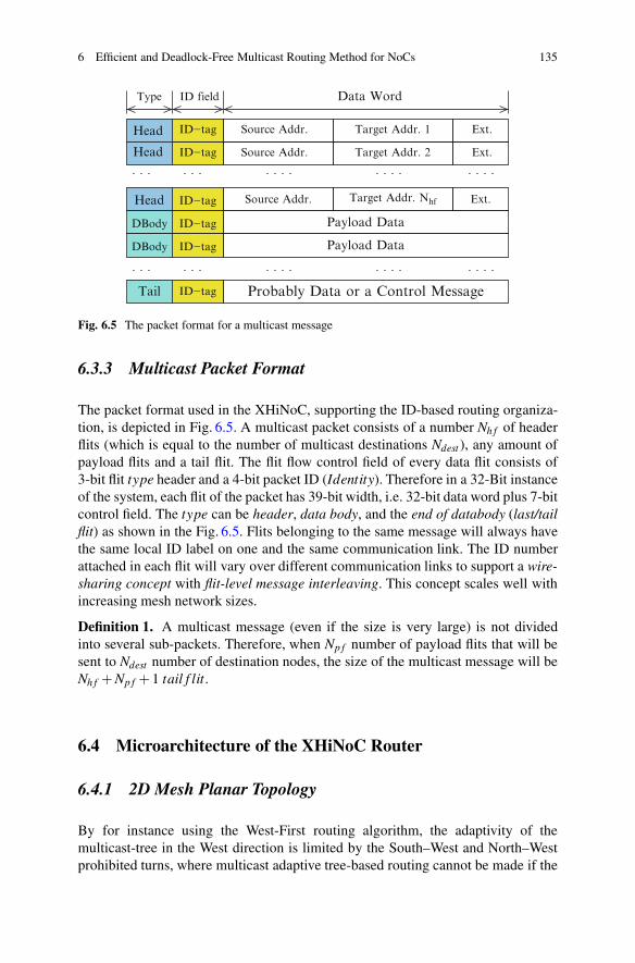
Fig. 6.5 The packet format for a multicast message
6.3.3 Multicast Packet Format
The packet format used in the XHiNoC, supporting the ID-based routing organiza-tion, is depicted in Fig. 6.5. A multicast packet consists of a number Nh f of headerflits (which is equal to the number of multicast destinations Ndest ), any amount ofpayload flits and a tail flit. The flit flow control field of every data flit consists of3-bit flit type header and a 4-bit packet ID (Identity). Therefore in a 32-Bit instanceof the system, each flit of the packet has 39-bit width, i.e. 32-bit data word plus 7-bitcontrol field. The type can be header, data body, and the end of databody (last/tailflit) as shown in the Fig. 6.5. Flits belonging to the same message will always havethe same local ID label on one and the same communication link. The ID numberattached in each flit will vary over different communication links to support a wire-sharing concept with flit-level message interleaving. This concept scales well withincreasing mesh network sizes.
Definition 1. A multicast message (even if the size is very large) is not dividedinto several sub-packets. Therefore, when Np f number of payload flits that will besent to Ndest number of destination nodes, the size of the multicast message will beNh f +Np f + 1 tail f lit.
6.4 Microarchitecture of the XHiNoC Router
6.4.1 2D Mesh Planar Topology
By for instance using the West-First routing algorithm, the adaptivity of themulticast-tree in the West direction is limited by the South–West and North–Westprohibited turns, where multicast adaptive tree-based routing cannot be made if the

136 F.A. Samman and T. Hollstein
y ad
dres
s
x address
4
3
2
1
0
43210
52 4
2421
191716
131211
76 8 9 10
18
1
22
15
20
25
14
X+subnet
X−subnet
3
23Fig. 6.6 2D planar meshnetwork
destination addresses are located in the South-West and North-West quadrant area[24]. These prohibited turns must be implemented in the routing algorithms to avoidthe occurrence of a deadlock configuration. In order to cover such problems, a planar2D NoC architecture with mesh topology is also presented in this chapter. The NoCis divided into two sub-networks in order to increase the degree of adaptivity of therouting functionality. A planar adaptive routing algorithm has been firstly introducedin [6], in which virtual channels (VCs) are introduced to support adaptive routingand to couple the sub networks. The main difference of the presented approach isthat, instead of using VCs, we replace them with a double physical communicationlink to increase the link and switch bandwidth capacity.
Figure 6.6 shows an example of the 2-D mesh 5 × 5 network. The Network-on-Chip is physically divided into two subnetworks i.e., X+(depicted in solid linearrows) and X−subnetworks (depicted in dashed line arrows). If the x-distancebetween source and target nodes (xo f f s = xtarget − xsource) is zero or positive, thenpackets will be routed using the X+subnetwork. If xo f f s is zero or negative, thenthe packets will be routed through the physical channels of the X−subnetwork.The ports connected with vertical y-direction links of X+ and X−subnetworks aredenoted by (North1, South1) and (North2, South2), respectively. The packets beingrouted through the X+subnetwork will have adaptivity to make West–North1, West–South1, North1–East and South1–East turns as well as West–East, North1–South1and South1–North1 straightforward (non-turn) routing direction. The packets beingrouted through the X−subnetwork will have adaptivity to make East–North2, East–South2, North2–West and South2–West turns as well as East–West, North2–South2and South2–North2 straightforward routing directions.
The planar adaptive routing technique on a mesh topology has been firstlyintroduced in [6] and is deadlock-free by principle. Instead of using virtual channelsto implement the interconnects between NORTH and SOUTH port as made in [6],

6 Efficient and Deadlock-Free Multicast Routing Method for NoCs 137
we prefer to implement two physical channels to separate the NORTH–SOUTHlink interconnects for the X+ and X−subnetworks. The objectives for this modifiedtopology are the preservation of the router performance and the increase of thenetwork bandwidth. In case that virtual channels would have been implementedbetween the NORTH and SOUTH ports, then we needed to add two virtual queuesat both incoming and outgoing ports. This would degrade the router performancecharacteristic or increase the data transfer latency, therefore we substitute VCs byadding two additional ports (NORTH2 and SOUTH2 ports) to the existing meshrouter.
In a typical 5-port mesh switch, a 2D N × M mesh network will haveN × (M − 1) + M × (N − 1) full-duplex directional communication links. Byusing 2D planar-based mesh router, the N ×M mesh network will provide morecommunication resources, i.e. 2N × (M− 1)+M× (N − 1) full-duplex directionallinks (and additionally the local core connections).
6.4.2 Static and 2D Planar Adaptive Routing Algorithms
In this chapter, we will evaluate different models of NoCs with mesh topology byusing four mesh prototypes with different routing algorithms. The first model (‘plnr’prototype) uses a 2D multicast planar adaptive routing algorithm that is presented inAlgorithm 4 and is implemented based on the planar mesh topology. The adaptiverouting decision is made based on the number of used ID slots (or the number offree ID slots) on each possible alternative routing direction and the record of therouting path made by other headers of the same message, which is later explained inSect. 6.5.3 and presented in Algorithm 2. The routing algorithm is divided into twosubalgorithms for X+ and X−subnetworks.
The second prototype (‘xy’ prototype) uses a static XY routing algorithm in thestandard mesh topology, where messages are first routed in horizontal X-directionand then to vertical Y-direction. Hence, North–East turn and North–West as wellas South–East and South–West are prohibited in the static XY routing algorithm.The remaining two models (‘wf-v1’ and ‘wf-v2’ prototypes) use the minimal West-First routing algorithms. In the West-First routing algorithm, packets will always befirstly routed to West direction, if its destination nodes are located in western arearelative from its source node or current position. When the destination nodes arelocated in eastern area of its source node or current position, then the packet can berouted adaptively to East, North or South directions [10].
6.4.3 Generic Modules and Modular Design
The XHiNoC router microarchitecture is developed based on a modular concept andunits are grouped into incoming block and outgoing block components as presented

138 F.A. Samman and T. Hollstein
REB
fullenW
enR emptyFIFO Queue
REB
fullenW
enR emptyFIFO Queue
MIM
r rN1
a a
PORT N
PORT N
PORT 1
PORT 1
connectsinter−
crossbarsel
AAsel
r rN1 2N21
a a
......
lluflavval full
MIM
a(N,N
)
a(1,N)
a(1,2)a(1,1)
r(1,N)
......
......r(1,2)r(1,1)
r(N,N
)......r(N
,2)r(N
,1)
a(N,1)
a(N,2)
......
r(N,1)
r(2,1)r(1,1)
......
......
......
......
a(N,1)
a(2,1)a(1,1)
r(1,N)
r(2,N)
r(N,N
)
a(1,N)
a(2,N)
a(N,N
)
Fig. 6.7 General XHiNoC router architecture
in Fig. 6.7. Each module is modeled based on generic code, which is strongly relatedto the number of input-output connectivities of each port. The components located atinput ports are FIFO buffers and a Routing Engine with Data Buffering (REB). Thecomponents located at output ports are an Arbiter (A) and a Crossbar Multiplexerwith ID-Management Unit (MIM). The working principles and mechanisms of theArbiter, REB and MIM units are explained in detail in [22] and [24].
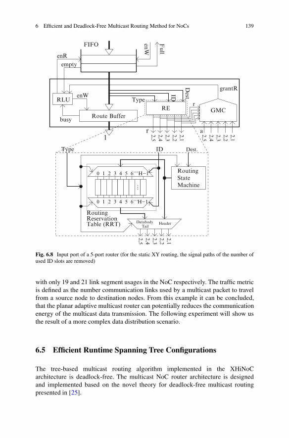
Figure 6.8 shows the components in an incoming port of the XHiNoC router. Inthe REB module, there are a Grant-Multicasting Controller (GMC), a Routing En-gine (RE), a Route Buffer and a Read-Logic Unit (RLU). The GMC consists ofcombinatorial logic and is used to control the acceptance of the multicast routingacknowledge (grant) signals from output ports. The RLU is also a combinatoriallogic, which is used to control the read-operation of a flit from the FIFO buffer intothe Route Buffer. When a routing direction for a flit is being decided by the REunit, then this flit will be concurrently buffered in the Route Buffer. This concurrentstep is introduced in order to reduce the number of internal pipeline stages in theXHiNoC router, and it can improve the router performance accordingly. The REunit consists of the Routing State Machine (RSM) and the Routing Reservation Table(RRT), which consists of a number of H preservable routing slots.
The design of the XHiNoC routers can be fully parametrized and customized ondemand. Each VHDL entity contains generic code, which enables the derivation ofnew VHDL modules with a specific architecture and a number of input/output pinsaccording to the specification. The custom-generic modular-based design approachalso enables us to easily generate irregular NoC topologies.
Before running a real experiment, the different routing paths that will beperformed by the aforementioned tree-based multicast routing methods (except forthe wf-v1 multicast method) are shown in Fig. 6.9. A multicast message is injectedfrom node (2,2) to 10 multicast destinations. The ‘xy’ multicast router performs24 link usages in the NoC. While the ‘plnr’ and ‘wf-v2’ multicast routers perform
6 Efficient and Deadlock-Free Multicast Routing Method for NoCs 139
Dest.RLU
enW
Full
FIFO
empty
enR
1
RE
grantR
r 2,12,2
2,42,5
2,3
Type
ID
r
enW
a 2,12,22,32,42,5
Route Buffer
RoutingStateMachine
ID Dest.Type
0 1 2 3 4 5 6
...
0 1 2 3 4 5 6 H−1...
...H−1
GMC
busy
RoutingReservationTable (RRT) Databody
TailHeader
2,12,22,32,42,5
Fig. 6.8 Input port of a 5-port router (for the static XY routing, the signal paths of the number ofused ID slots are removed)
with only 19 and 21 link segment usages in the NoC respectively. The traffic metricis defined as the number communication links used by a multicast packet to travelfrom a source node to destination nodes. From this example it can be concluded,that the planar adaptive multicast router can potentially reduces the communicationenergy of the multicast data transmission. The following experiment will show usthe result of a more complex data distribution scenario.
6.5 Efficient Runtime Spanning Tree Configurations
The tree-based multicast routing algorithm implemented in the XHiNoCarchitecture is deadlock-free. The multicast NoC router architecture is designedand implemented based on the novel theory for deadlock-free multicast routingpresented in [25].

140 F.A. Samman and T. Hollstein
5
4
3
2
1
0
0 1 2 3 4 5
y−Address
x−Address
SourceNode
DestinationNode
Planar (plnr)AdaptiveMulticast
Static XYTree−basedMulticast
MulticastTree−based
Adaptive WF−v2
Fig. 6.9 The traffic patterns by using static tree-based, minimal adaptive west-first and minimalplanar adaptive multicast routing methods
The problem of inefficient runtime spanning tree configuration that can affect theoverall throughput of the generated multicast trees [24]. Because of this uncoveredissue, in any circumstance, the adaptive routing cannot show better performance,since the data rate of the multicast tree depends on the slowest data rate in allspanning trees or branches of the multicast tree. Therefore, based on the presentedlocal ID management concept, an efficient method for runtime multicast spanningtree configurations by using a minimal adaptive routing algorithms based on a so-called pheromone tracking strategy is proposed in this contribution. Minimizing thesize of spanning trees (total multicast communication traffic) will not only reducethe communication energy but also decrease the probability of forming spanningtrees having slower data rates.
6.5.1 Routing and Multicasting Procedure
The routing engine (RE) units in XHiNoC consist of combination of a Routing StateMachine (RSM) unit and a Routing Reservation Table (RRT) unit. The combinationis aimed at supporting a runtime link interconnect configuration.

6 Efficient and Deadlock-Free Multicast Routing Method for NoCs 141
Definition 2. A Multicast Routing Slot within a Routing Reservation Table isdefined as
Tmcs(k,rdir) ∈ {0,1} (6.1)
where k ∈ Ω = {0,1,2, · · · ,Nslot − 1}, Nslot is the number of ID slots on a link. rdir
is a routing direction, where rdir ∈ D ={
1,2,3, · · · ,Nout p}
, and Nout p is the numberof I/O ports in a router.
Definition 3. A Routing Reservation Table (RRT) of the RE unit at an input port ofa multicast router is defined as
T (k) = [Tmcs(k,1) Tmcs(k,2) · · · Tmcs(k,Nout p)] (6.2)
T (k) contains a binary-element vector. Hence, T has 2D (matrix) size of row ×column = Nslot ×Nout p.
Based on Definitions 2 and 3, a binary-encoded multicast routing directionrbin
dir = enc(rdir) is introduced and has a size of Nout p number of binary elements.For example, if Nout p = 5, then enc(1) = [1 0 0 0 0], enc(2) = [0 1 0 0 0],enc(3) = [0 0 1 0 0], enc(4) = [0 0 0 1 0] and enc(5) = [0 0 0 0 1]. Algorithm 1describes the ID-based Routing Organization between the RSM and the RRT unit. Ifa RE unit identifies a flit F(type, I) as a header flit (type = header) from the outputof a FIFO buffer with local ID-tag I ∈ Γ, where Γ = Ω then the routing function ofRSM unit fRSM(Adest) will determine a routing direction rdir. This means that therdir is calculated logically based on destination address Adest attached in the headerflit and current address of the router, and the routing direction is written in the slotnumber k = I of the RRT unit. In the next time periods, when the RE units identifypayload flits with the same ID-tag number (ID-tag number I) with the previouslyforwarded header flit, then their routing direction will be taken up directly from theslot number k = I in the RRT unit.
Algorithm 1 Runtime IDMA-based multicast routing mechanism
Read Data Flit from Queue : Fn (type, I)1: k ⇐ I; Adest is obtained from Header flits2: BEGIN Multicast routing (rbin
dir )3: if type is Header then4: rdir ⇐ fRSM (Adest); T (k,rdir)⇐ 15: rbin
dir = enc(rdir)6: else if type is Response then7: rdir ⇐ fRSM (Adest)8: rbin
dir = enc(rdir)9: else if type is Databody then
10: rbindir ⇐ T (k)
11: else if type is Tail then12: rbin
dir ⇐ T (k); T (k)⇐ /013: end if14: END Multicast routing

142 F.A. Samman and T. Hollstein
Branch A
Branch B
Input portOutput port
Bra
nch
B
R2
R4R3
R1
Fig. 6.10 Example of aninefficient spanning tree inadaptive tree-basedmulticasting
There are three main steps to send a multicast message towards multipledestinations. The first step is to forward all header flits for the multicast tree routingsetup and ID-slot reservation. The second step is to multicast (replicate) the payloadflits to follow the path set up previously by the header flits. The last step is to setfree the reserved local ID-slot by the tail flit. The detail procedure can be found in[24] and is formally described in Algorithm 1.
Definition 4. A runtime tree-based multicast routing configuration of a messagethat will be sent to a number of Ndest multicast destinations is established by sendingNh f number of header flits, where Ndest = Nh f . The multicast header flits Hj(I), j ∈{
1,2, · · · ,Nh f}
can be ordered arbitrarily, where I is the ID-tag of the headers at acertain (input) link n. Thus, we can further define that Fn(header, I) = Hj(I).
6.5.2 Inefficient Spanning Tree Problem
The aim of an efficient adaptive multicast routing is to minimize the communicationenergy. Figure 6.10 shows an example of an inefficient adaptive routing. A tree-based multicast message coming from the WEST input port of the router R1 formstwo branches in different routing directions i.e., a branch to NORTH (branch A)and a branch to EAST (branch B) direction. It can be assumed, that the branchesA and B are established by header flit 1 and header flit 2, belonging to the samemulticast message. The header flits will be routed to multicast destinations (xt1,yt1)and (xt2,yt2), respectively, by using a minimal adaptive routing algorithm.
Postulate 1. In a regular 2D mesh network, if a header flit Hj(I) in a current meshnode (x,y) will be routed to a destination node (x j,y j) by using a minimal adaptiverouting algorithm, then there will be at most two alternative output port directions(otherwise the routing path would not be minimal). When |xo f f s, j|= |x j−x|> 0 and|yo f f s, j| = |y j − y|> 0, then there will be two alternative output directions, i.e. m1
and m2, where if m1 is an output direction that can reduce |xo f f s, j|, then m2 is anoutput direction that can reduce |yo f f s, j|, or vice versa.

6 Efficient and Deadlock-Free Multicast Routing Method for NoCs 143
R4 R4
R4 R4
Output port Input port
Bra
nch
B
Bra
nch
A
Branch B
Branch BBranch A
Branch ABranch B
Branch A
a
c d
bFig. 6.11 Consequences ofthe inefficient spanning trees
In the router R3 in Fig. 6.10, the multicast message is routed from SOUTHto EAST direction (branch A), while in the router R2, the multicast message isrouted from WEST to NORTH direction (branch B). Finally these two branchesare then routed to the same router (router R4). In this case, the multicast treebranches (spanning trees) are inefficient in term of communication energy. Thecommunication energy can be reduced if the router R1 performs only the multicasttree branch A or branch B.
Postulate 2. If two header flits (Hj(I) and Hk(I)) having the same ID-tag I (hence,belonging to the same multicast message) are routed from the same input port nin a router node (x,y) at two consecutive times tHj and tHk where tHj < tHk (whichmeans that Hj is routed firstly before Hk), then an inefficient runtime spanning treeconfiguration can happen when Hk (which will be routed to destination node (xk,yk),where |xo f f s,k|= |xk−x|> 0 and |yo f f s,k|= |yk−y|> 0) does not follow to an outputport m which has also been selected previously for routing of Hj (having destinationnode (x j,y j)), where 〈x j − x = xo f f s, j = xo f f s,k and y j − y = yo f f s, j = yo f f s,k〉 or〈xo f f s, j = 0 and yo f f s, j = yo f f s,k〉 or 〈xo f f s, j = xo f f s,k and yo f f s, j = 0〉.
Figure 6.11 depicts four possible situations that can occur in the router R4 asthe further disadvantageous consequences of the inefficient multicast spanning treesconfigured from Fig. 6.10. These situations can happen since the number of free IDslots on each communication link as the parameter of the adaptive routing algorithmmay change dynamically. Figure 6.11a, b show a tree-branch crossover problem, inwhich the inefficient spanning trees are propagated through different outgoing ports.If we assume that the current address of router R4 is (xcurr,ycurr) and the targetnodes of the tree branches A and B are (xt1,yt1) and (xt2,yt2) such that xo f f set1 =xt1 − xcurr > 0 and yo f f set1 = yt1 − ycurr > 0 as well as xo f f set2 = xt2 − xcurr > 0 andyo f f set2 = yt2 − ycurr > 0, then in any circumstance, the inefficient situation mighthappen again in the next intermediate nodes.

144 F.A. Samman and T. Hollstein
Figure 6.11c, d illustrate a tree-branch interference problem, where the inefficientspanning trees interfere into the same outgoing port. This situation will lead toinefficient multicast communication time (increase of communication latency anddata workloads) because of the self-contention problem. Two multicast messageswill be forwarded from different input ports to the same output port, carryingidentical data payload (double workloading).
6.5.3 Solution: Efficient Adaptive Routing Selectionwith Pheromone Tracking Strategy
The problematic configurations presented in Figs. 6.10 and 6.11 are not onlyinefficient in terms of communication energy (because the inefficient traffic willoverburden the NoC), but also in term of communication latency, since theinefficient traffic can degrade the data rate of the multicast traffic. The problemsreduce the NoC performance while increasing power consumption.
We solve the aforementioned problem not by designing a specific multicastpath optimization algorithm that should be run at compile time or before injectingmulticast messages (pre-processing algorithm). Compile-time path optimizationalgorithms such as the optimal spanning tree algorithm are suitable for sourcerouting approach, where the routing paths for the overall pathes of a multicastmessage from source to destination node are determined at source node before themessage is injected to the network. In contrast, in XHiNoC the routing algorithmused to route unicast and multicast messages is the same, the routing decisions aremade at runtime and locally executed hop-by-hop on every port of each router. Thus,we do not follow the approach of a path pre-processing optimization algorithm forthe sake of initiation-time-efficiency.
In order to avoid the previously described problems, each time a routing enginehas two alternative output ports for making a routing decision, then a new adaptiveoutput selection strategy between two alternative output ports will be applied. Asimple abstract view of the adaptive selection strategy is outlined in Algorithm 2.The basic concept of the proposed algorithm is the identification of the track records(pheromone trails) of other previously-routed header flits that belong to the samemulticast message. This concept is designed in order to avoid inefficient spanningtrees branches of the multicast tree.
Definition 5. A pheromone trail checking is an operation to check the binary stateof the multicast routing slots Tmcs(k,m1) and Tmcs(k,m2). The operation is made bya header flit Hj(I) having ID-tag number I = k that will be alternatively routed tooutput directions m1 and m2, where m1,m2 ∈ D.
The hardware implementation of the efficient adaptive routing selection functionwith pheromone tracking strategy will not result in a more complex operation inthe XHiNoC microarchitecture. The router complexity can be reduced naturally

6 Efficient and Deadlock-Free Multicast Routing Method for NoCs 145
Algorithm 2 Multicast: adaptive routing selection strategy1: Begin Function Select(port m1, port m2)2: if Routing can be made to port m1 and port m2 then3: if Routing for the same Multicast Packet has been made to port m1 and not
yet to port m2 then4: Return Routing = port m15: else if Routing for the same Multicast Packet has been made to port m2 and
not yet to port m1 then6: Return Routing = port m27: else if Routing for the same Multicast Packet has not been made to port m1
and port m2, or has been made both to port m1 and port m2 then8: if UsedID(port m1)<UsedID(port m2) then9: Return Routing = port m1
10: else11: Return Routing = port m212: end if13: end if14: end if15: End Function
Algorithm 3 Logical view of Algorithm 2
Incoming Data Flit : Fn (type, ID)T (k,m) : The slot of RRT for a flit with ID=k to direction mUsedID(m) : Number of used/reserved ID slots in direction m
1: Begin Function Select(m1, m2)2: k ⇐ ID3: if ¬T (k,m1) & UsedID(m1)≤ ¬T (k,m2) & UsedID(m2) then4: Return m15: else if ¬T (k,m1) & UsedID(m1)> ¬T (k,m2) & UsedID(m2) then6: Return m27: end if8: End Function
by using the advantageous feature of our dynamic runtime table-based routingmanagement and control. In order to achieve an efficient operation, the logical viewof the multicast adaptive routing selection strategy is proposed in Algorithm 3.
The operation of Algorithm 3 (logical view of the efficient adaptive multicastrouting algorithm) in accordance with Definition 5 (pheromone trail checkingstrategy) will be illustrated and explained in the following example. Let usassume that a multicast header having ID-tag k = 3 can be alternatively routedto output port m1 and m2, where the number of used (already reserved) ID-tags at the output ports is UsedID(m1) = 0101(5) and UsedID(m2) = 0010(2),respectively. Let us also assume that a previously routed header, which belongsto the same multicast group as the current header (also with ID-tag k = 3), hasbeen routed to port m1 such that T (3,m1) = 1, and there is no header with ID-tag k = 3 that has been routed to port m2 such that T (3,m2) = 0. Based on
146 F.A. Samman and T. Hollstein
Output Port
Input Port
Header 2of packet A
usedID=0
usedID=1 orusedID>1
?
?
Header 1of packet A
Alternatiftree 1
Pheromone ofpacket A madeby Header 1
(1,2)
(1,3)
(1,4)
(1,1)
(2,2)
(2,1)
(2,3)
(2,4)
Target nodeof Header 2
(3,1)
(3,2)
(3,3)
(3,4)
Alternativetree 2
2D PlanarRouter
Wes
t
Eas
t
North2North1
South1 South2
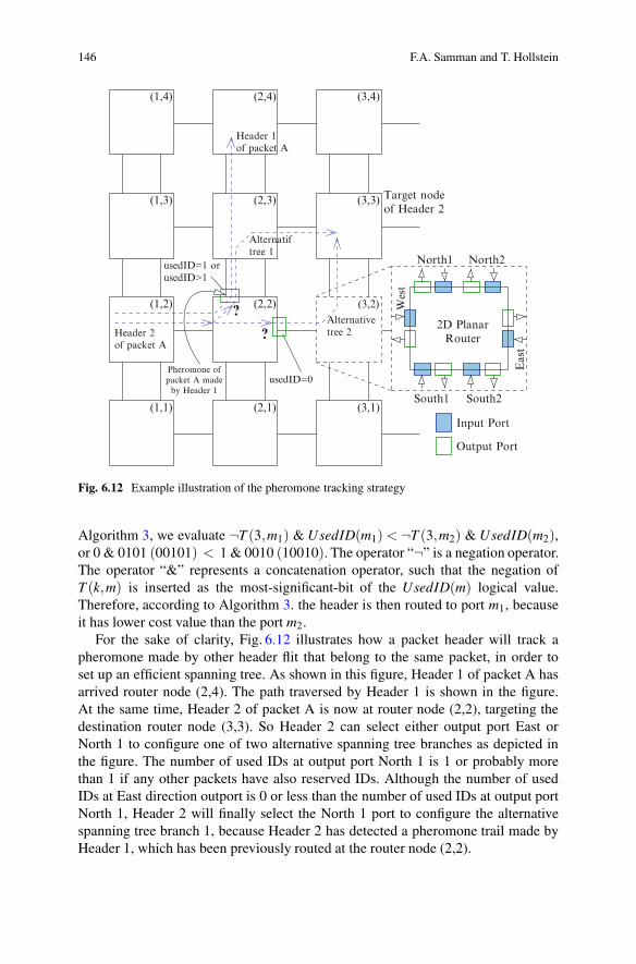
Fig. 6.12 Example illustration of the pheromone tracking strategy
Algorithm 3, we evaluate ¬T (3,m1) & UsedID(m1) < ¬T (3,m2) & UsedID(m2),or 0 & 0101 (00101) < 1 & 0010 (10010). The operator “¬” is a negation operator.The operator “&” represents a concatenation operator, such that the negation ofT (k,m) is inserted as the most-significant-bit of the UsedID(m) logical value.Therefore, according to Algorithm 3. the header is then routed to port m1, becauseit has lower cost value than the port m2.
For the sake of clarity, Fig. 6.12 illustrates how a packet header will track apheromone made by other header flit that belong to the same packet, in order toset up an efficient spanning tree. As shown in this figure, Header 1 of packet A hasarrived router node (2,4). The path traversed by Header 1 is shown in the figure.At the same time, Header 2 of packet A is now at router node (2,2), targeting thedestination router node (3,3). So Header 2 can select either output port East orNorth 1 to configure one of two alternative spanning tree branches as depicted inthe figure. The number of used IDs at output port North 1 is 1 or probably morethan 1 if any other packets have also reserved IDs. Although the number of usedIDs at East direction outport is 0 or less than the number of used IDs at output portNorth 1, Header 2 will finally select the North 1 port to configure the alternativespanning tree branch 1, because Header 2 has detected a pheromone trail made byHeader 1, which has been previously routed at the router node (2,2).

6 Efficient and Deadlock-Free Multicast Routing Method for NoCs 147
According to Definition 5 and Algorithm 3, Header 2 can detect the pheromoneof Header 1 and track/follow the same spanning tree made by the Header 1, becauseboth header flits belong to the same packet, i.e. both have the same local ID-tagat each communication link. From Fig. 6.12, we can see that by following thepheromone tracking strategy, Header 2 will finally add only one communicationlink (link between nodes (2,3)–(3,3), through alternative tree 1), instead of twocommunication links (links between nodes (2,2)–(3,2) and between node (3,2)–(3,3), through alternative tree 2). Therefore, the communication energy of themulticast communication performed by the packet A will be less and the overallcommunication more efficient.
It it is obvious, that the pheromone trail tracking can be efficiently and logicallyimplemented by detecting the bit-value of the routing slot T (k,m). This detectedbit is used as the most-significant bit (MSB) in the concatenation operation withthe UsedID bit-signal, i.e. T (k,m)&UsedID(m). In general, the router will route aheader flit into an output port having more free ID-tags. However, the pheromonetrail, which is represented by the routing slot T (k,m), has a higher priority over thenumber of already reserved ID slots. This pheromone trail checking method is usedto avoid inefficient multicast spanning tree as presented visually in Fig. 6.10.
In this section four algorithms that are used to route packets in NoCs have beenpresented. Algorithm 1 is an ID-based routing algorithm that is generally used inthe XHiNoC router by default. Algorithm 4 represents a planar adaptive routingscheme, that routes packets in the 2D planar NoC using two sub-networks with dualphysical channels in the north and south direction. The most important contributingalgorithms are Algorithms 2 and 3. These algorithms are solving the problem ofthe inefficient adaptive tree-based multicast. The algorithms can also be simplyderived and implemented based on the existing physical state information of therouter microarchitecture.
6.6 Experimental Results
In this section, four XHiNoC multicast router prototypes with different multicastrouting algorithms are compared. The first prototype is a multicast router workingwith a planar adaptive routing algorithm on a NoC mesh architecture, which ispresented with ‘plnr’ acronym in the figures. The second prototype applies astatic XY multicast routing algorithm on the mesh standard architecture (‘xy’). Thethird and fourth prototype are multicast routers in a standard mesh architectureapplying an adaptive West-First (WF) routing algorithm (‘wf-v1’ and ‘wf-v2’).The adaptive WF multicast router version 1 (‘wf-v1’) is a multicast router withoutimplementation of an adaptive selection strategy to avoid an inefficient spanningtree (branches of the multicast tree) as presented in [24]. Thus in this prototype, themulticast trees are formed freely without considering the track records of the otherpreviously-routed header flits belonging to the same multicast group. The adaptiveWF multicast router version 2 (‘wf-v2’) implements the adaptive selection strategypresented in the Algorithm 2 to avoid an inefficient spanning tree problem.

148 F.A. Samman and T. Hollstein
Algorithm 4 2D Planar adaptive routing algorithm
Network is partitioned into two subnets: X+ and X− Subnet.Set of output ports in X+ Subnet: {EAST,SOUTH 1,NORT H 1,LOCAL}.Set of output ports in X− Subnet: {WEST,SOUTH 2,NORTH 2,LOCAL}.Select(m1,m2) is selection function between output port m1 orm2.
1: Xo f f s = Xtarget −Xsource2: Yo f f s = Ytarget −Ysource
3: while Packet is in Subnet X+ i.e.(Xo f f s ≥ 0) do4: if Xo f f s = 0 and Yo f f s = 0 then5: Routing = LOCAL6: else if Xo f f s = 0 and Yo f f s > 0 then7: Routing = NORT H 18: else if Xo f f s = 0 and Yo f f s < 0 then9: Routing = SOUTH 1
10: else if Xo f f s > 0 and Yo f f s = 0 then11: Routing = EAST12: else if Xo f f s > 0 and Yo f f s > 0 then13: Routing=Select(NORTH 1,EAST )14: else if Xo f f s > 0 and Yo f f s < 0 then15: Routing=Select(SOUTH 1,EAST )16: end if17: end while18: while Packet is in Subnet X− i.e.(Xo f f s ≤ 0) do19: if Xo f f s = 0 and Yo f f s = 0 then20: Routing = LOCAL21: else if Xo f f s = 0 and Yo f f s > 0 then22: Routing = NORT H 223: else if Xo f f s = 0 and Yo f f s < 0 then24: Routing = SOUTH 225: else if Xo f f s < 0 and Yo f f s = 0 then26: Routing =WEST27: else if Xo f f s < 0 and Yo f f s > 0 then28: Routing=Select(NORTH 2,WEST )29: else if Xo f f s < 0 and Yo f f s < 0 then30: Routing=Select(SOUTH 2,WEST )31: end if32: end while
The experiment is setup by applying a multicast random data distribution (traffic)scenario to validate the theorem and methodology of the proposed deadlock-freemulticast routing. Figure 6.13 depicts the distribution of the source-destinationunicast-multicast communication partners in the 2D 8× 8 mesh architecture (64network nodes). The numerical symbol at the bottom and the left side of themesh network represents the 2D node x-address and y-address. From the figureit can be seen, that 9 multicast communication partners (M6, M8) and 4 unicastcommunication pairs (U) are placed. Three of 9 multicast communication sourceshave 8 multicast targets (M8), while the remaining 6 multicast sources have 6multicast destinations (M6).

6 Efficient and Deadlock-Free Multicast Routing Method for NoCs 149
82 3 4 5 6 71
9 10 11 12 13 14 15 16
17 18 19 20 21 22 23 24
25 26 27 28 29 30 31 32
33 34 35 36 37 38 39 40
41 42 43 44 45 46 47 48
49 50 51 52 53 54 55 56
57 58 59 60 61 62 63 64
U
U U
M6
M8
U
M8
M8
M6M6
M6
M6
M6
0 1 2 3 4 5 6 7
0
1
2
3
4
5
6
7
40
56
56
16
16
16
34
34
31
31
2
22
16 31 58 34 37 58 2
58 40 31 31 25 56 2 37
56 37 40 25 34 2 58 56
31 56 16 64 57 56 25 34
40 37 2 8 1 16 34 25
56
16
2 40 40
25
25
37
37
5816
Fig. 6.13 Distribution of the source-destination communication partners
Every NoC router in Fig. 6.13 is depicted with a square block with numericalattributes. A numerical symbol in the small square block at the top-left side of aNoC router node represents the node number. The numerical symbol at the top-rightside in the NoC router node represents the communication partner of the node, fromwhich the NoC router node will receive a message. For example, the network nodeat node address (2,1) (2D node address, 2 is the x-horizontal address and 1 is they-vertical address) has node number 11. At the top-right side in this node, we seethe numerical value 31 (this means that the node will receive a packet from meshnode 31 located in the node address (6,3)).
The boldface symbols (U, M6 and M8) at the bottom-left corner of the routerbox represent that the network node will send a unicast message (U) or a multicastmessage with a number of 6 target nodes (M6) or 8 target nodes (M8). For example,the mesh node at address (7,1) (mesh node number 16) is attributed with (M8).This means that the node will send a multicast message into 8 destination nodes.We can find the target nodes of the multicast message sent from the mesh nodenumber 16 by identifying mesh nodes having numerical symbol 16 at the right-side in the router box. In order to find easily the partners of each unicast andmulticast communications, Table 6.1 gives an overview on the unicast and multicastcommunication partners/groups of the source-destination distribution presented inFig. 6.13.
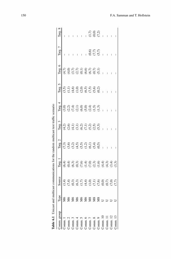
150 F.A. Samman and T. Hollstein
Tab
le6.
1U
nica
stan
dm
ultic
astc
omm
unic
atio
nsfo
rth
era
ndom
mul
ticas
ttes
ttra
ffic
scen
ario
Com
m.g
roup
Type
Sour
ceTa
rg.1
Targ
.2Ta
rg.3
Targ
.4Ta
rg.5
Targ
.6Ta
rg.7
Targ
.8
Com
m.1
M6
(1,4
)(6
,4)
(7,3
)(4
,2)
(3,0
)(3
,5)
(4,7
)–
–C
omm
.2M
6(7
,4)
(0,4
)(3
,6)
(2,6
)(2
,2)
(1,1
)(4
,0)
––
Com
m.3
M6
(0,3
)(6
,3)
(3,2
)(4
,1)
(7,4
)(4
,6)
(3,7
)–
–C
omm
.4M
6(6
,3)
(0,3
)(4
,5)
(3,1
)(2
,1)
(1,0
)(2
,7)
––
Com
m.5
M6
(1,7
)(7
,6)
(5,5
)(6
,2)
(6,0
)(2
,0)
(0,1
)–
–C
omm
.6M
6(4
,4)
(1,4
)(1
,2)
(7,1
)(5
,0)
(6,5
)(6
,6)
––
Com
m.7
M8
(1,0
)(7
,0)
(6,1
)(5
,2)
(2,4
)(7
,5)
(6,7
)(0
,6)
(1,7
)C
omm
.8M
8(7
,1)
(2,3
)(5
,4)
(2,5
)(1
,5)
(5,6
)(0
,7)
(7,7
)(0
,0)
Com
m.9
M8
(7,6
)(1
,6)
(0,5
)(5
,3)
(1,3
)(0
,2)
(5,1
)(5
,7)
(7,2
)C
omm
.10
U(0
,0)
(4,4
)–
––
––
––
Com
m.1
1U
(0,7
)(4
,3)
––
––
––
–C
omm
.12
U(7
,0)
(3,4
)–
––
––
––
Com
m.1
3U
(7,7
)(3
,3)
––
––
––
–

6 Efficient and Deadlock-Free Multicast Routing Method for NoCs 151
350400450500550600650700750800850900950a
b
0.100 0.125 0.200 0.250 0.500
Ave
rage
Ban
dwid
th (
MB
/s)
Injection Rate (num. of flits/cycle/producer)
plnrxy
wf−v2wf−v1
22000240002600028000300003200034000360003800040000420004400046000480005000052000
0.100 0.125 0.200 0.250 0.500
Tai
l flit a
ccep
t. (
clk
cycl
es)
Injection Rate (num. of flits/cycle/producer)
plnrxy
wf−v2wf−v1
Fig. 6.14 Average bandwidth and tail flit arrival latency measurement versus expected datainjection rates for multicast random test scenario. (a) Average bandwidth. (b) Average tail flitlatency
6.6.1 Performance Measurements
The measurements of the average bandwidth and tail flit acceptance latency withvarious expected data injection rates are depicted in Fig. 6.14. The measurements aremade for five different expected data injection rates, i.e. 0.1, 0.125, 0.2, 0.25 and 0.5flits/cycle (fpc) where each source node injects a 5000-flit packet (equivalent with4× 5,000 = 20 kB data words). It seems that for all multicast routing algorithms, theaverage BW increases as the injection rate is increased. However, the average BWwill tend to saturate, when the injection rate is set nearly to maximum injection rate(the maximum injection rate is 1 flit/cycle).
152 F.A. Samman and T. Hollstein
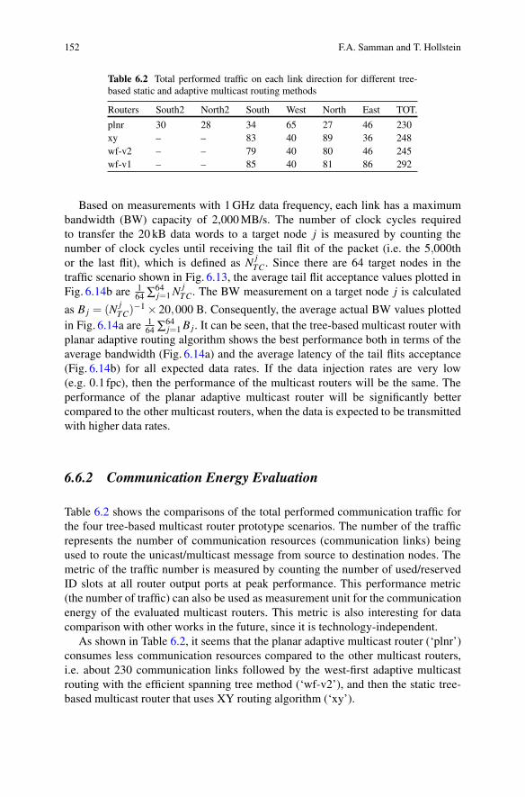
Table 6.2 Total performed traffic on each link direction for different tree-based static and adaptive multicast routing methods
Routers South2 North2 South West North East TOT.
plnr 30 28 34 65 27 46 230xy – – 83 40 89 36 248wf-v2 – – 79 40 80 46 245wf-v1 – – 85 40 81 86 292
Based on measurements with 1 GHz data frequency, each link has a maximumbandwidth (BW) capacity of 2,000 MB/s. The number of clock cycles requiredto transfer the 20 kB data words to a target node j is measured by counting thenumber of clock cycles until receiving the tail flit of the packet (i.e. the 5,000thor the last flit), which is defined as N j
TC. Since there are 64 target nodes in thetraffic scenario shown in Fig. 6.13, the average tail flit acceptance values plotted inFig. 6.14b are 1
64 ∑64j=1 N j
TC. The BW measurement on a target node j is calculated
as B j = (N jTC)
−1 × 20,000 B. Consequently, the average actual BW values plottedin Fig. 6.14a are 1
64 ∑64j=1 B j. It can be seen, that the tree-based multicast router with
planar adaptive routing algorithm shows the best performance both in terms of theaverage bandwidth (Fig. 6.14a) and the average latency of the tail flits acceptance(Fig. 6.14b) for all expected data rates. If the data injection rates are very low(e.g. 0.1fpc), then the performance of the multicast routers will be the same. Theperformance of the planar adaptive multicast router will be significantly bettercompared to the other multicast routers, when the data is expected to be transmittedwith higher data rates.
6.6.2 Communication Energy Evaluation
Table 6.2 shows the comparisons of the total performed communication traffic forthe four tree-based multicast router prototype scenarios. The number of the trafficrepresents the number of communication resources (communication links) beingused to route the unicast/multicast message from source to destination nodes. Themetric of the traffic number is measured by counting the number of used/reservedID slots at all router output ports at peak performance. This performance metric(the number of traffic) can also be used as measurement unit for the communicationenergy of the evaluated multicast routers. This metric is also interesting for datacomparison with other works in the future, since it is technology-independent.
As shown in Table 6.2, it seems that the planar adaptive multicast router (‘plnr’)consumes less communication resources compared to the other multicast routers,i.e. about 230 communication links followed by the west-first adaptive multicastrouting with the efficient spanning tree method (‘wf-v2’), and then the static tree-based multicast router that uses XY routing algorithm (‘xy’).

6 Efficient and Deadlock-Free Multicast Routing Method for NoCs 153
0123456789
1011121314a
b
1 2 3 4 5 6 7 8 9 10 11 12 13 14 15 16 17 18 19 20 21 22 23 24 25 26 27 28 29 30 31 32
Res
erve
d ID
Slo
ts
Network node
plnrxy
wf−v2wf−v1
0123456789
1011121314
33 34 35 36 37 38 39 40 41 42 43 44 45 46 47 48 49 50 51 52 53 54 55 56 57 58 59 60 61 62 63 64
Res
erve
d ID
Slo
ts
Network node
plnrxy
wf−v2wf−v1
Fig. 6.15 Reserved (used) overall ID slots for multicast random test scenarios. (a) Node 1–32.(b) Node 32–64
In order to see the traffic configurations in the network in detail, Fig. 6.15 showsthe 2D view of the total ID slot reservations in every NoC router node. Figure 6.15adepicts the total reserved ID slots for the NoC router node 1 until node 32, whileFig. 6.15a shows the total ID slots reservation for the NoC router node 33 untilnode 64. As depicted in Fig. 6.15, the west-first adaptive routing algorithm withoutthe efficient spanning tree method (‘wf-v1’) reserves more ID-slots than the otherrouting algorithms at several router nodes.
154 F.A. Samman and T. Hollstein
6.7 State-of-the-Art of Multicast RoutingTechniques for NoCs
One basic class of methods for routing multicast messages in mesh-based NoCs aretree-based multicast routing techniques. In tree-based multicast routing, a headerordering before submission of the packet within the source node is not required (theorder of the destination addresses can be freely determined). The multicast routingwill form communication paths like branches of trees connecting the source nodewith the destination nodes at the end points of the tree branches. The work in [4,19]and [14] have presented the concept and methodology to route multicast messagesby using tree-based methods, which has been utilized in general internetworkingcontext. The work in [25] has presented a new theory for deadlock free tree-based multicast routing for networks-on-chip area (mesh topology). The theory isdeveloped based on a dynamic local ID-tag routing organization and the concept ofa hold-release tagging mechanism.
Alternatively, multicast messages can also be routed by applying path-basedmulticast routing methods. Here, as a prerequisite, a multiple target ordering isrequired before the multicast packets are sent to the network. The path-basedmulticast routing requires a full implementation of an adaptive routing algorithmallowing all turns in the mesh-based network topology. Therefore, virtual channelsare usually needed to make a deadlock free multicast routing function. Virtualchannels in the context of on-chip interconnection network will consume not onlylarger logic gate area but also larger power dissipation. The works in [9, 15, 16]and [5] have presented the path-based multicast routing methods for a mesh-basednetwork topology.
In the Network-on-Chip (NoC) research area, some multicast NoC architectureshave been introduced. Most of them use the tree-based multicast routing method[1, 11, 12, 28], and path-based multicast routing method [8, 13, 18, 21]. The virtualcircuit tree multicast (VCTM) NoC [12] for example has presented a NoC that usesvirtual circuit tree numbers to configure routing paths. However, compared to thepresented approach, which uses runtime dynamic local ID configuration, the VCTMNoC applies a static method, where virtual circuit tables are statically partitionedamong nodes.
A few NoC environments also proposed specific multicast routing methodologiessuch as a closed-loop path routing method [17] and a region-based routing method[21]. The recursive partitioning multicast (RPM) NoC [28], as another example,applies a recursive hop-by-hop network partitioning method to multicast packets ateach intermediate node. The packets in the RPM NoC make replication at a certainnode to multicast packets. The replicated packets will update the destination listattached on their header flit and make a new network partitioning recursively basedon their current position. By using such scheme, the RPM method will increase thecomplexity of the routing computational logic.
Table 6.3 presents several NoCs that propose and provide multicast routingservices for packet routing. Most of the NoC approaches route the network packets

6 Efficient and Deadlock-Free Multicast Routing Method for NoCs 155
Tab
le6.
3St
ate-
of-t
he-a
rts
ofm
ulti
cast
rout
ing
tech
niqu
esfo
rN
oCs
Mul
tica
stm
etho
dSw
itch
ing
met
hod
Rou
ting
adap
tivit
yV
Cbu
ffer
s,(b
uffe
rde
pth)
Log
icar
ea(t
echn
olog
y)Sp
ecifi
cfe
atur
es
VC
TM
[12]
Tre
e-ba
sed
Cir
cuit
swit
chin
gA
dapt
ive,
stat
icja
.4,8
(d.n
.a)
0.02
40d
mm
2
(70
nm)
Vir
tual
circ
uitt
ree,
stat
icV
C-t
able
part
itio
ning
RPM
[28]
Tre
e-ba
sed
Wor
mho
led.
o.ta
rget
dist
ribu
tion
ja.4
(4)
4.0e
mm
2
(65
nm)
Rec
ursi
vepa
rtit
ioni
ng,
prio
rity
-bas
edre
plic
atio
nL
DPM
[8]
Path
-bas
edW
orm
hole
Odd
-eve
nad
aptiv
eja
a .4(8
)21
,050
gate
s(0
.25
μm)
Path
-bas
edw
ith
opti
miz
edde
stin
atio
nor
deri
ngbL
BD
R[2
1]R
egio
n-ba
sed
Wor
mho
leSt
atic
,ada
ptiv
eex
t.d.
n.a
(d.n
.a)
0.04
99m
m2
(90
nm)
Tra
ffic
isol
atio
ns,n
etw
ork
dom
ain
part
itio
ning
MR
R[1
]T
ree-
base
dV
irtu
alcu
t-th
roug
hA
dapt
ive
no.(
20,2
0,10
)bd.
n.a
Ext
rain
tern
alri
ngbu
ffer
s(r
otar
yro
uter
)O
PT,L
XY
RO
PT[1
1]T
ree-
base
dC
ircu
itA
dapt
ive
wes
t-fir
stja
.4(3
)d.
n.a
Pre-
proc
essi
ngal
gori
thm
for
tree
gene
rati
onV
C-A
/D-F
D[1
3]Pa
th-b
ased
Wor
mho
le,
VC
TSt
atic
,ada
ptiv
eja
.4(8
/10)
c1,
172.
03f
Mλ
2
(65
nm)
FIFO
wit
had
dres
s/da
tade
coup
ling
Cus
tom
Mca
st[2
9]T
ree-
base
dPa
cket
Stat
icno
.(4)
0.18
–3.0
6m
m2
(70
nm)
Mul
tica
stro
utin
gat
desi
gn-t
ime
(sta
tic)
CO
MC
[18]
Path
-bas
edW
orm
hole
Stat
icja
.4,6
(2)
d.n.
aC
onne
ctio
n-or
ient
edpa
th-b
ased
mul
tica
stT
DM
-VC
C[1
7]C
lose
d-lo
oppa
thC
ircu
itSt
atic
no.(
d.n.
a)d.
n.a
Pre-
proc
essi
ngal
gori
thm
for
TD
Mci
rcui
tcon
figur
atio
nX
HiN
oCT
ree-
base
dW
orm
hole
cut-
thro
ugh
Ada
ptiv
e2-
net
plan
arno
.(2)
0.13
78m
m2
(130
nm)
Run
tim
edy
nam
iclo
calI
Dm
anag
emen
t
d.n.
a.de
tail
nota
vail
able
,d.o
.dep
end
on,e
xt.e
xten
dabl
e,V
Cvi
rtua
lcha
nnel
,VC
Tvi
rtua
lcut
-thr
ough
a Impl
emen
ted
asde
liver
ych
anne
lbuf
fers
toav
oid
mul
tica
stde
adlo
ckb20
phit
sin
buff
erin
gse
gmen
tsta
ge,2
0in
outp
utst
age,
10in
inpu
tsta
gec V
Cle
ngth
is8
for
addr
ess,
10fo
rda
tadO
nly
the
tabl
e(5
12en
trie
s),n
otth
eov
eral
llog
icar
eaof
the
rout
ere O
neti
lear
ea(i
nclu
sive
tile
proc
esso
r)f T
hear
eais
for
adap
tive
rout
erw
ith
wor
mho
lesw
itch
ing
(no
furt
her
expl
anat
ion
abou
tthe
λun
it)

156 F.A. Samman and T. Hollstein
by using wormhole switching method. The table compares some aspects regardingrouter implementation and their specific features. Some information cannot beprovided in the table, because the data is not available from the consideredpublications in the bibliography. As shown in the table, compared to the otherNoCs, the XHiNoC can be implemented with a very small size buffer (single bufferwith only two data slots per input port). The FIFO Buffer is a NoC component thatcan consume relatively large logic area compared to other NoC components. It canalso have a large power dissipation due to intensive switching activities of data thatoccurs in the buffer.
In Multiprocessor Systems-on-Chip (MPSoC) and chip-level multiprocessorsystem (CMP) applications, multicast communication services are an important andessential issue. Recent works related to NoC-based multicast communication arepresented in [29] and [17]. The work in [29] presents the problem of synthesizingcustom NoC architectures that are optimized for a given application (which iscritical, when dependability aspects are considered as well). The there presentedmulticast method considers both unicast and multicast traffic flow in the inputspecification. But the work proposes a static solution for deadlock-free multicastrouting that is fixed to specific NoC applications, i.e. the applications must beknown before chip fabrication. The work presented in [17] proposes a TDM (TimeDivision Multiplex)-based virtual circuit configuration (TDM-VCC) where a pre-processing algorithm for time slot allocations is made before injecting multicastmessages into the NoC. In some specific embedded system applications, the inter-core communication patterns are known. Therefore, a pre-processing static routingfor congestion avoiding techniques can be used [20, 29], expectedly resulting in amuch simpler router architecture (pre-manufacturing routing technique). Runtimedynamic adaptive routing methods [2, 3, 22] are however an interesting approachin the NoC-based multicore embedded systems, where applications may not beknown in advance and dependability and reconfiguration plays a role. Indeed, someembedded IC vendors in the multicore era could potentially not only market IP coresbut also system architectures [7], where many applications can be mapped onto thesystem architectures product (IP+NoC cores). Therefore, the implementation of theruntime dynamic adaptive tree-based multicast routing will simplify an embeddedsystem design flow because the routing information configuration is not neededanymore on the post-manufacture (on-chip) router. In this context however, theruntime techniques will need extra area cost and complexity.
6.8 Summary
In general, NoC routers applying planar adaptive routing schemes can achieve animproved performance because of the higher bandwidth capacity of the NoC indouble vertical links connecting NORTH and SOUTH ports. Nevertheless, thisperformance gain must be paid by logic and routing area overhead to implementthe mesh planar router architecture.

6 Efficient and Deadlock-Free Multicast Routing Method for NoCs 157
The tree-based multicast routing presented in this chapter belongs to the class ofruntime distributed routing techniques, in which routing decisions are made locallyduring application execution time (runtime) on every router/switch node based ona header’s destination address. The advantage of this method is, that it scales wellwith increasing NoC sizes. Hence, the presented technique to prevent the inefficientspanning tree problems has been proven to be feasible and deliver good results.Compared to static methods it will probably result in a suboptimal or near-optimalmulticast spanning tree, but in certain cases, a global optimal spanning tree may beattained.
When a static tree-based multicast routing would be used, then the configuredmulticast spanning trees will always be the similar, although the order of the headerprobes is changed. For a fixed traffic scenario, the global optimal multicast spanningtree could be attained by finding an optimum ordering of the header flits in onemulticast message. The optimum ordering is strongly dependent on the multicasttraffic patterns. Such a procedure would require the computation of an optimumordering algorithm before injecting multicast packets at source nodes. However, thesupplement effort will lead to extra computational power and delay, due to the extrapre-processing at the source nodes. Furthermore, the result can also be sub-optimal,since the traffic situation in the network can vary.
This issue has exactly been addressed within the presented approach, whichconsiders local traffic situations dynamically and minimizes the communication re-source and energy usage. When the presented adaptive routing algorithms are used,then the spanning tree is formed independently at runtime by header probing andadditional consideration of the local traffic situation. The spanning tree topology canvary with the order of header flits in the multicast message and with indeterministicdynamically varying traffic loads in the network.
References
1. P. Abad, V. Puente, J.-A. Gregorio, MRR: enabling fully adaptive multicast routing for CMPinterconnection networks, in Proceedings of the 15th IEEE International Symposium on HighPerformance Computer Architecture (HPCA 2009), Shanghai, 2009, pp. 355–366
2. M.A. Al Faruque, T. Ebi, J. Henkel, Run-time adaptive on-chip communication scheme, inProceedings of the 2007 IEEE/ACM International Conference on Computer-Aided Design(ICCAD’07), San Jose (IEEE Press, Piscataway, 2007), pp. 26–31
3. G. Ascia, V. Catania, M. Palesi, D. Patti, Implementation and analysis of a new selectionstrategy for adaptive routing in networks-on-chip. IEEE Trans. Comput. 57(6), 809–820 (2008)
4. M. Barnett, D.G. Payne, R.A. van de Geijn, J. Watts, Broadcasting on meshes with worm-holerouting. J. Parallel Distrib. Comput. 35(2), 111–122 (1996)
5. R.V. Boppana, S. Chalasani, C.S. Raghavendra, Resource deadlocks and performance ofwormhole multicast routing algorithms. IEEE Trans. Parallel Distrib. Syst. 9(6), 535–549(1998)
6. A.A. Chien, J.H. Kim, Planar adaptive routing: low-cost adaptive networks for multiprocessors,in Proceedings of the 19th International Symposium on Computer Architecture, Gold Coast,May 1992, pp. 268–277

158 F.A. Samman and T. Hollstein
7. M. Coppola, M.D. Grammatikakis, R. Locatelli, G. Maruccia, L. Pieralisi, Design of Cost-Efficient Interconnect Processing Units: Spidergon STNoC (CRC/Taylor & Francis, BocaRaton, 2009)
8. M. Daneshtalab, M. Ebrahimi, S. Mohammadi, A. Afzali-Kusha, Low-distance path-basedmulticast routing algorithm for network-on-chips. IET Comput. Digit. Tech. 3(5), 430–442(2009)
9. J. Duato, A theory of deadlock-free adaptive multicast routing in wormhole networks. IEEETrans. Parallel Distrib. Syst. 6(9), 976–987 (1995)
10. J. Duato, S. Yalamanchili, L. Ni, Interconnection Networks: An Engineering Approach,Revised Printing (Morgan Kaufmann, San Francisco, 2003)
11. W. Hu, Z. Lu, A. Jantsch, H. Liu, Power-Efficient tree-based multicast support for networks-on-chip, in Proceedings of the 16th Asia and South Pacific Design Automation Conference(ASP-DAC’11), Yokohama, 2011, pp. 363–368
12. N.E. Jerger, L.S. Peh, M. Lipasti, Virtual circuit tree multicasting: a case for on-chip hardwaremulticast support, in Proceedings of the 35th Annual Internationl Symposium on ComputerArchitecture (ISCA’08), Beijing, 2008, pp. 229–240
13. K.-M. Keung, A. Tyagi, Breaking adaptive multicast deadlock by virtual channel address/dataFIFO decoupling, in Proceedings of the 2nd International Workshop on Network-on-ChipArchitecture (NoCArch’09), New York, 2009, pp. 11–16
14. D.R. Kumar, W.A. Najjar, P.K. Srimani, A new adaptive hardware tree-based multicast routingin K-Ary N-cubes. IEEE Trans. Comput. 50(7), 647–659 (2001)
15. X. Lin, L.M. Ni, Multicast communication in multicomputer networks. IEEE Trans. ParallelDistrib. Syst. 4(10), 1105–1117 (1993)
16. X. Lin, P.K. McKinley, L.M. Ni, Deadlock-free multicast wormhole routing in 2-D meshmulticomputers. IEEE Trans. Parallel Distrib. Syst. 5(8), 793–804 (1994)
17. Z. Lu, A. Jantsch, TDM virtual-circuit configuration for network-on-chip. Trans. Very Larg.Scale Integr. Syst. 16(8), 1021–1034 (2008)
18. Z. Lu, B. Yi, A. Jantsch, Connection-oriented multicasting in wormhole-switched network-on-chip, in Proceedings of the IEEE Computer Society Annual Symposium on VLSI (ISVLSI’06),Karlsruhe, 2006, pp. 205–210
19. M.P. Malumbres, J. Duato, J. Torrelas, An efficient implementation of tree-based multicastrouting for distributed shared-memory multiprocessors, in Proceedings of the 8th IEEESymposium on Parallel and Distributed Processing, New Orleans, 1996, pp. 186–189
20. M. Palesi, R. Holsmark, S. Kumar, V. Catania, Application specific routing algorithms fornetworks on chip. IEEE Trans. Parallel Distrib. Syst. 20(3), 316–330 (2009)
21. S. Rodrigo, J. Flich, J. Duato, M. Hummel, Efficient unicast and multicast support for CMPs, inProceedings of the 41st IEEE/ACM International Symposium on Microarchitecture (MICRO-41), 2008, pp. 364–375
22. F.A. Samman, T. Hollstein, M. Glesner, Multicast parallel pipeline router architecture fornetwork-on-chip, in Proceedings of the Design, Automation and Test in Europe Conferenceand Exhibition (DATE’08), Munich, Mar 2008, pp. 1396–1401
23. F.A. Samman, T. Hollstein, M. Glesner, Networks-on-Chip based on dynamic wormhole packetidentity management. VLSI Des. J. Hindawi Publ. Corp. 2009, 1–15 (2009)
24. F.A. Samman, T. Hollstein, M. Glesner, Adaptive and deadlock-free tree-based multicastrouting for networks-on-chip. IEEE Trans. Very Larg. Scale Integr. Syst. 18(7), 1067–1080(2010)
25. F.A. Samman, T. Hollstein, M. Glesner, New theory for deadlock-free multicast routing inwormhole-switched virtual-channelless networks-on-chip. IEEE Trans. Parallel Distrib. Syst.22(4), 544–557 (2011)
26. F.A. Samman, T. Hollstein, M. Glesner, Wormhole cut-through switching: flit-level messagesinterleaving for virtual-channelless network-on-chip. Elsevier Sci. J. Microprocess. Microsyst.Embed. Hardw. Des. 35(3), 343–358 (2011)

6 Efficient and Deadlock-Free Multicast Routing Method for NoCs 159
27. F.A. Samman, T. Hollstein, M. Glesner, Planar adaptive network-on-chip supporting deadlock-free and efficient tree-based multicast routing method. Elsevier Sci. J. Microprocess. Microsyst.Embed. Hardw. Des. 36(6), 449–461 (2012)
28. L. Wang, Y. Jin, H. Kim, E.J. Kim, Recursive partitioning multicast: a bandwidth-efficientrouting for networks-on-chip, in Proceedings of the 3rd ACM/IEEE International Symposiumon Networks-on-Chip (NOCS’09), San Diego, 2009, pp. 64–73
29. S. Yan, B. Lin, Custom networks-on-chip architectures with multicast routing. Trans. VeryLarg. Scale Integr. Syst. 17(3), 342–355 (2009)
30. H. Zimmermann, OSI reference model – the ISO model of architecture for open systemsinterconnection. IEEE Trans. Commun. 8(4), 425–432 (1980)