Embed Size (px)
Citation preview

1
Chapter 5The LC-3
Based on slides © McGraw-HillAdditional material © 2004/2005 Lewis/Martin
5-2CSE 240
Instruction Set Architecture
ISA = Programmer-visible components & operations• Memory organization
Address space -- how may locations can be addressed? Addressibility -- how many bits per location?
• Register set How many? What size? How are they used?
• Instruction set Opcodes Data types Addressing modes
All information needed to write/gen machine language program
5-3CSE 240
LC-3 Overview: Memory and RegistersMemory
• Address space: 216 locations (16-bit addresses)• Addressibility: 16 bits
Registers• Temporary storage, accessed in a single machine cycle
Memory access generally takes longer• Eight general-purpose registers: R0 - R7
Each 16 bits wideHow many bits to uniquely identify a register?
• Other registersNot directly addressable, but used by (and affected by)
instructionsPC (program counter), condition codes, MAR, MDR, etc.
5-4CSE 240
LC-3 Overview: Instruction SetOpcodes
• 16 opcodes• Operate instructions: ADD, AND, NOT, (MUL)• Data movement instructions: LD, LDI, LDR, LEA, ST, STR, STI• Control instructions: BR, JSR, JSRR, RET, RTI, TRAP• Some opcodes set/clear condition codes, based on result
N = negative (<0), Z = zero (=0), P = positive (> 0)Data Types
• 16-bit 2’s complement integerAddressing Modes
• How is the location of an operand specified?• Non-memory addresses: register, immediate (literal)• Memory addresses: base+offset, PC-relative, indirect

2
5-5CSE 240
LC-3 InstructionSummary(inside back cover)
5-6CSE 240
Operate InstructionsOnly three operations
• ADD, AND, NOT
Source and destination operands are registers• Do not reference memory• ADD and AND can use “immediate” mode,
(i.e., one operand is hard-wired into instruction)
Will show abstracted datapath with each instruction• Illustrate when and where data moves to accomplish desired op.
5-7CSE 240
NOT (Register)
Note: DR and SR could be the same register
15 14 13 12 11 10 9 8 7 6 5 4 3 2 1 0
1 0 0 1 DR SR 1 1 1 1 1 1NOT
Register File
R7R6R5R4R3R2R1R0
1010111100001111
0101000011110000
ALU
AB
1616
NOT
ADD R3 R51 0 0 1 0 1 1 1 0 1 1 1 1 1 1 1IR
16Convention
sourcedestination
5-8CSE 240
ADD (Register) this zero means “register mode”
15 14 13 12 11 10 9 8 7 6 5 4 3 2 1 0
0 0 0 1 DR SR1 0 0 0 SR2ADD
Register File
R7R6R5R4R3R2R1R0
0000000000001001
0000000000001000
1111111111111111
ALU
AB
1616
ADD
ADD R3 R5 R00 0 0 1 0 1 1 1 0 1 0 0 0 0 0 0IR
16
3
5-9CSE 240
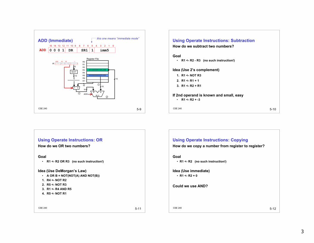
ADD (Immediate) this one means “immediate mode”
15 14 13 12 11 10 9 8 7 6 5 4 3 2 1 0
0 0 0 1 DR SR1 1 imm5ADD
Register File
R7R6R5R4R3R2R1R0
0000000000001001
0000000000001000
ALU
AB
1616
ADD
ADD R3 R5 -10 0 0 1 0 1 1 1 0 1 1 1 1 1 1 1IR
SEXT
5
16
1111111111111111
1 016
16
5-10CSE 240
Using Operate Instructions: SubtractionHow do we subtract two numbers?
Goal• R1 <- R2 - R3 (no such instruction!)
Idea (Use 2’s complement)1. R1 <- NOT R32. R1 <- R1 + 13. R1 <- R2 + R1
If 2nd operand is known and small, easy• R1 <- R2 + -3
5-11CSE 240
Using Operate Instructions: ORHow do we OR two numbers?
Goal• R1 <- R2 OR R3 (no such instruction!)
Idea (Use DeMorgan’s Law)• A OR B = NOT(NOT(A) AND NOT(B))1. R4 <- NOT R22. R5 <- NOT R33. R1 <- R4 AND R54. R5 <- NOT R1
5-12CSE 240
Using Operate Instructions: CopyingHow do we copy a number from register to register?
Goal• R1 <- R2 (no such instruction!)
Idea (Use immediate)• R1 <- R2 + 0
Could we use AND?

4
5-13CSE 240
Using Operate Instructions: ClearingHow do we set a register to 0?
Goal• R1 <- 0 (no such instruction!)
Idea• R1 <- R1 AND 0
Could we use ADD?
5-14CSE 240
Data Movement InstructionsLoad: read data from memory to register
• LD: PC-relative mode• LDR: base+offset mode• LDI: indirect mode
Store: write data from register to memory• ST: PC-relative mode• STR: base+offset mode• STI: indirect mode
Load effective address• Compute address, save in register, do not access memory• LEA: immediate mode
5-15CSE 240
PC-Relative Addressing ModeWant to specify address directly in the instruction
• But an address is 16 bits, and so is an instruction!• After subtracting 4 bits for opcode and 3 bits for register, we have 9 bits
available for address
Observation• Needed data often near currently executing instruction
Solution• Add 9 bits in instruction (sign extended) to PC (of next instructionnext instruction) to
form address
Example: LD: R1 <- M[PC+SEXT(IR[8:0])]
5-16CSE 240
LD (PC-Relative)15 14 13 12 11 10 9 8 7 6 5 4 3 2 1 0
0 0 1 0 DR PCoffset9LD
Register File
R7R6R5R4R3R2R1R0
0000000000001001
ALU
ABADD
LD R3 -810 0 0 1 0 1 1 1 1 0 1 0 1 1 1 1IR
SEXT
9
16
1111111110101111
0 1 0 0 0 0 0 0 0 0 0 1 1 0 0 1PC
16
MAR MEMORY MDR
Rd16
16

5
5-17CSE 240
ST (PC-Relative)15 14 13 12 11 10 9 8 7 6 5 4 3 2 1 0
0 0 1 1 SR PCoffset9ST
Register File
R7R6R5R4R3R2R1R0
0000000000001001
ALU
ABADD
ST R3 -810 0 1 1 0 1 1 1 1 0 1 0 1 1 1 1IR
SEXT
9
16
1111111110101111
0 1 0 0 0 0 0 0 0 0 0 1 1 0 0 1PC
16
MAR MEMORY MDR
Wr16
16
5-18CSE 240
Base + Offset Addressing ModeProblem
• With PC-relative mode, can only address words “near” the instruction• What about the rest of memory?
Solution• Use a register to generate a full 16-bit address
Idea• 4 bits for opcode, 3 for src/dest register, 3 bits for base register• Remaining 6 bits are used as a signed offset• Offset is sign-extended before adding to base register• I.e., Instead of adding offset to PC, add it to base register
Example: LDR: R1 <- M[R2+SEXT(IR[5:0])]
5-19CSE 240
LDR (Base+Offset)15 14 13 12 11 10 9 8 7 6 5 4 3 2 1 0
0 1 1 0 DR BaseR offset6LDR
Register File
R7R6R5R4R3R2R1R0
000000001000000
0000000000001001
ALU
ABADD
LDR R3 R5 -170 1 1 0 0 1 1 1 0 1 1 0 1 1 1 1IR
SEXT
6
16
1111111111101111
MAR MEMORY MDR
Rd16
16
16
5-20CSE 240
STR (Base+Offset)15 14 13 12 11 10 9 8 7 6 5 4 3 2 1 0
0 1 1 1 SR BaseR offset6STR
Register File
R7R6R5R4R3R2R1R0
000000001000000
0000000000001001
ALU
ABADD
STR R3 R5 -170 1 1 1 0 1 1 1 0 1 1 0 1 1 1 1IR
SEXT
6
16
1111111111101111
MAR MEMORY MDR
Wr16
16
16
6
5-21CSE 240
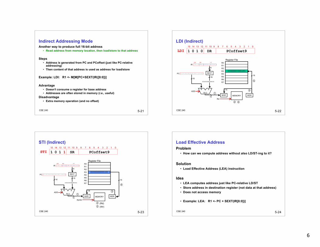
Indirect Addressing ModeAnother way to produce full 16-bit address
• Read address from memory location, then load/store to that address
Steps• Address is generated from PC and PCoffset (just like PC-relative
addressing)• Then content of that address is used as address for load/store
Example: LDI: R1 <- M[M[PC+SEXT(IR([8:0])]
Advantage• Doesn't consume a register for base address• Addresses are often stored in memory (i.e., useful)
Disadvantage• Extra memory operation (and no offset)
5-22CSE 240
LDI (Indirect)15 14 13 12 11 10 9 8 7 6 5 4 3 2 1 0
1 0 1 0 DR PCoffset9LDI
Register File
R7R6R5R4R3R2R1R0
0000000000001001
ALU
ABADD
LDI R3 -171 0 1 0 0 1 1 1 0 1 1 0 1 1 1 1IR
SEXT
9
16
1111111101101111
MAR MEMORY MDR
Rd16
0 1 0 0 0 0 0 0 0 0 0 1 1 0 0 1PC
16
16
16
5-23CSE 240
STI (Indirect)15 14 13 12 11 10 9 8 7 6 5 4 3 2 1 0
1 0 1 1 SR PCoffset9STI
Register File
R7R6R5R4R3R2R1R0
0000000000001001
ALU
ABADD
(Rd)
STI R3 -171 0 1 1 0 1 1 1 0 1 1 0 1 1 1 1IR
SEXT
9
16
1111111101101111
MAR MEMORY MDR
Rd/Wr16
0 1 0 0 0 0 0 0 0 0 0 1 1 0 0 1PC
16
16
(Wr)
16
5-24CSE 240
Load Effective AddressProblem
• How can we compute address without also LD/ST-ing to it?
Solution• Load Effective Address (LEA) instruction
Idea• LEA computes address just like PC-relative LD/ST• Store address in destination register (not data at that address)• Does not access memory
• Example: LEA: R1 <- PC + SEXT(IR[8:0])]

7
5-25CSE 240
LEA15 14 13 12 11 10 9 8 7 6 5 4 3 2 1 0
1 1 1 0 DR PCoffset9LEA
Register File
R7R6R5R4R3R2R1R0
0011111110001000
ALU
ABADD
LEA R3 -811 1 1 0 0 1 1 1 1 0 1 0 1 1 1 1IR
SEXT
9
16
1111111110101111
0 1 0 0 0 0 0 0 0 0 0 1 1 0 0 1PC
16 16
5-26CSE 240
Example
1 0 1 0 0 1 1 1 1 1 1 1 0 1 1 1
0 1 1 1 0 1 0 0 0 1 0 0 1 1 1 0
0 0 0 1 0 1 0 0 1 0 1 0 0 1 0 1
0 1 0 1 0 1 0 0 1 0 1 0 0 0 0 0
0 0 1 1 0 1 0 1 1 1 1 1 1 0 1 1
0 0 0 1 0 1 0 0 0 1 1 0 1 1 1 0
1 1 1 0 0 0 1 1 1 1 1 1 1 1 0 1
Instruction
R3 ← M[M[x30F4]](R3 ← M[x3102])
(R3 ← 5)
M[R1+14] ← R2(M[x3102] ← 5)
R2 ← R2 + 5 = 5
R2 ← 0
M[PC-5(x30F4)] ← R2
R2 ← R1 + 14 = x3102
R1 ← PC-3 (x30F4)
Comments
x30FC
x30FB
x30FA
x30F9
x30F8
x30F7
x30F6
Address
opcode
STR0111
LDI1010
LEA1110
AND0101
ST0011
ADD0001Machine Language
5-27CSE 240
Aside: Machine Language Programming Is Hard!
(Altair 8800, 1975)
5-28CSE 240
Control InstructionsAlter the sequence of instructions
• Changing the Program Counter (PC)
Conditional Branch• Branch taken if a specified condition is true
New PC computed relative to current PC• Otherwise, branch not taken
PC is unchanged (I.e., points to next sequential instruction)
Unconditional Branch (or Jump)• Always changes the PC• Target address computed PC-relative or Base+Offset
TRAP• Changes PC to start of OS “service routine”• When routine is done, execution resumes after TRAP
8
5-29CSE 240
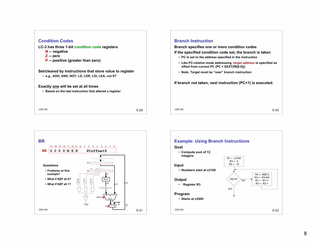
Condition CodesLC-3 has three 1-bit condition code registers
N -- negativeZ -- zeroP -- positive (greater than zero)
Set/cleared by instructions that store value to register• e.g., ADD, AND, NOT, LD, LDR, LDI, LEA, not ST
Exactly one will be set at all times• Based on the last instruction that altered a register
5-30CSE 240
Branch InstructionBranch specifies one or more condition codesIf the specified condition code set, the branch is taken
• PC is set to the address specified in the instruction
• Like PC-relative mode addressing, target address is specified asoffset from current PC (PC + SEXT(IR[8:0]))
• Note: Target must be “near” branch instruction
If branch not taken, next instruction (PC+1) is executed.
5-31CSE 240
BR15 14 13 12 11 10 9 8 7 6 5 4 3 2 1 0
0 0 0 0 N Z P PCoffset9BR
ALU
ABADD
BR N Z P -10 0 0 0 0 1 1 1 1 1 1 1 1 1 1 1IR
SEXT
9
16
1111111111111111
0 1 0 0 0 0 0 0 0 0 0 1 1 0 0 1PC
16
1 0
16
0N
1Z
0P
16Yes!
0 1 0 0 0 0 0 0 0 0 0 1 1 0 0 0
16
Questions• Problems w/ this
example?
• What if NZP all 0?
• What if NZP all 1?
5-32CSE 240
Example: Using Branch InstructionsGoal
• Compute sum of 12integers
Input• Numbers start at x3100
Output• Register R3
Program• Starts at x3000
R1 ← x3100R3 ← 0R2 ← 12
R2=0?
R4 ← M[R1]R3 ← R3+R4R1 ← R1+1R2 ← R2-1
NO
YES

9
5-33CSE 240
Example: Summing Program
R2 ← 00 1 0 1 0 1 0 0 1 0 1 0 0 0 0 0x3002
R1 ← R1+10 0 0 1 0 0 1 0 0 1 1 0 0 0 0 1x3007R2 ← R2-10 0 0 1 0 1 0 0 1 0 1 1 1 1 1 1X3008
0 0 0 0 1 1 1 1 1 1 1 1 1 0 1 0
0 0 0 1 0 1 1 0 1 1 0 0 0 1 0 0
0 1 1 0 1 0 0 0 0 1 0 0 0 0 0 0
0 0 0 0 0 1 0 0 0 0 0 0 0 1 0 1
0 0 0 1 0 1 0 0 1 0 1 0 1 1 0 0
0 1 0 1 0 1 1 0 1 1 1 0 0 0 0 0
1 1 1 0 0 0 1 0 1 1 1 1 1 1 1 1
Instruction
BRnzp x3004
R3 ← R3+R4
R4 ← M[R1]
BRz x300A
R2 ← 12
R3 ← 0
R1 ← x3001+xFF (x3100)
Comments
x3009
x3006
x3005
x3004
x3003
x3001
x3000
Address
LDR0110
BR0000
LEA1110
AND0101
ADD0001
5-34CSE 240
Jump InstructionsJump is an unconditional branch (i.e., always taken)
Destination• PC set to value of base register encoded in instruction• Allows any branch target to be specified• Pros/Cons versus BR?
5-35CSE 240
JMP15 14 13 12 11 10 9 8 7 6 5 4 3 2 1 0
1 1 0 0 0 0 0 BaseR 0 0 0 0 0 0JMP
Register File
R7R6R5R4R3R2R1R0
000001000011000
JMP R51 1 0 0 0 0 0 1 0 1 0 0 0 0 0 0IR
16
0 1 0 0 0 1 0 0 0 0 0 1 1 0 0 1PC
0 0 0 0 0 1 0 0 0 0 0 1 1 0 0 0
1 016
16
5-36CSE 240
TRAP
Calls operating system “service routine”• Identified by 8-bit trap vector• Execution resumes after OS code executes (more later)
15 14 13 12 11 10 9 8 7 6 5 4 3 2 1 0
1 1 1 1 0 0 0 0 trapvect8TRAP
halt the program (HALT)x25
output a character to the monitorx21
input a character from the keyboardx23
routinevector
10
5-37CSE 240
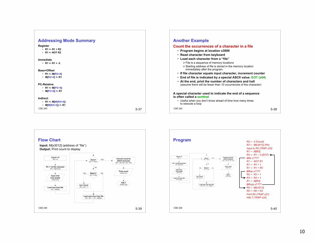
Addressing Mode SummaryRegister
• R1 <- R1 + R2• R1 <- NOT R2
Immediate• R1 <- R1 + -2
Base+Offset• R1 <- M[R2+4]• M[R2+4] <- R1
PC-Relative• R1 <- M[PC+6]• M[PC+6] <- R1
Indirect• R1 <- M[M[R2+4]]• M[M[R2+4]] <- R1
5-38CSE 240
Another ExampleCount the occurrences of a character in a file
• Program begins at location x3000• Read character from keyboard• Load each character from a “file”
File is a sequence of memory locationsStarting address of file is stored in the memory location
immediately after the program• If file character equals input character, increment counter• End of file is indicated by a special ASCII value: EOT (x04)• At the end, print the number of characters and halt
(assume there will be fewer than 10 occurrences of the character)
A special character used to indicate the end of a sequenceis often called a sentinel
• Useful when you don’t know ahead of time how many timesto execute a loop
5-39CSE 240
Flow Chart
Count = 0(R2 = 0)
Ptr = 1st file character(R3 = M[x3012])
Input char
from keybd(TRAP x23)
Done?(R1 ?= EOT)
Load char from file(R1 = M[R3])
Match?(R1 ?= R0)
Incr Count(R2 = R2 + 1)
Load next char from file(R3 = R3 + 1, R1 = M[R3])
Convert count to
ASCII character(R0 = x30, R0 = R2 + R0)
Print count(TRAP x21)
HALT(TRAP x25)
NO
NO
YES
YES
Input: M[x3012] (address of “file”)Output: Print count to display
5-40CSE 240
Program R2 ← 0 (Count)R3 ← M[x3012] (Ptr)Input to R0 (TRAP x23)R1 ← M[R3]R4 ← R1 – 4 (EOT)BRz x????R1 ← NOT R1R1 ← R1 + 1R1 ← R1 + R0BRnp x????R2 ← R2 + 1R3 ← R3 + 1R1 ← M[R3]BRnzp x????R0 ← M[x3013]R0 ← R0 + R2Print R0 (TRAP x21)HALT (TRAP x25)
Count = 0(R2 = 0)
Ptr = 1st file character(R3 = M[x3012])
Input char
from keybd(TRAP x23)
Done?(R1 ?= EOT)
Load char from file(R1 = M[R3])
Match?(R1 ?= R0)
Incr Count(R2 = R2 + 1)
Load next char from file(R3 = R3 + 1, R1 = M[R3])
Convert count to
ASCII character(R0 = x30, R0 = R2 + R0)
Print count(TRAP x21)
HALT(TRAP x25)
NO
NO
YES
YES

11
5-41CSE 240
Program (1 of 2)
Input to R0 (TRAP x23)1 1 1 1 0 0 0 0 0 0 1 0 0 0 1 1x3002
R1 ← R1 + 10 0 0 1 0 0 1 0 0 1 1 0 0 0 0 1x3007R1 ← R1 + R00 0 0 1 0 0 1 0 0 1 0 0 0 0 0 0X3008
0 0 0 0 1 0 1 0 0 0 0 0 0 0 0 1
1 0 0 1 0 0 1 0 0 1 1 1 1 1 1 1
0 0 0 0 0 1 0 0 0 0 0 0 1 0 0 0
0 0 0 1 1 0 0 0 0 1 1 1 1 1 0 0
0 1 1 0 0 0 1 0 1 1 0 0 0 0 0 0
0 0 1 0 0 1 1 0 0 0 0 1 0 0 0 0
0 1 0 1 0 1 0 0 1 0 1 0 0 0 0 0
Instruction
BRnp x300B
R1 ← NOT R1
BRz x300E
R4 ← R1 – 4 (EOT)
R1 ← M[R3]
R3 ← M[x3012] (ptr)
R2 ← 0 (counter)
Comments
x3009
x3006
x3005
x3004
x3003
x3001
x3000
Address
LD0010
BR0000
TRAP1111
AND0101
ADD0001
5-42CSE 240
Program (2 of 2)
R1 ← M[R3]0 1 1 0 0 0 1 0 1 1 0 0 0 0 0 0x300C
HALT (TRAP x25)1 1 1 1 0 0 0 0 0 0 1 0 0 1 0 1x3011
Starting Address of FileX30120 0 0 0 0 0 0 0 0 0 1 1 0 0 0 0
1 1 1 1 0 0 0 0 0 0 1 0 0 0 0 1
0 0 0 1 0 0 0 0 0 0 0 0 0 0 1 0
0 0 1 0 0 0 0 0 0 0 0 0 0 1 0 0
0 0 0 0 1 1 1 1 1 1 1 1 0 1 1 0
0 0 0 1 0 1 1 0 1 1 1 0 0 0 0 1
0 0 0 1 0 1 0 0 1 0 1 0 0 0 0 1
Instruction
ASCII x30 (‘0’)
Print R0 (TRAP x21)
R0 ← R0 + R2
R0 ← M[x3013]
BRnzp x3004
R3 ← R3 + 1
R2 ← R2 + 1
Comments
x3013
x3010
x300F
x300E
x300D
x300B
x300A
Address
LD0010
BR0000
TRAP1111
AND0101
ADD0001
5-43CSE 240
LC-3Data PathRevisited
Filled arrow = info to be processed.
Unfilled arrow= control signal.
5-44CSE 240
Data Path ComponentsGlobal bus
• Set of wires that carry 16-bit signals to many components• Inputs to bus are “tri-state devices”
Place signal on bus when enabledOnly one (16-bit) signal should be enabled at a timeControl unit decides which signal “drives” the bus
• Any number of components can read busRegister only captures bus data if write-enabled by the
control unit
Memory and I/O• Control and data registers for memory and I/O devices• Memory: MAR, MDR (also control signal for read/write)• Input (keyboard): KBSR, KBDR• Output (text display): DSR, DDR

12
5-45CSE 240
Data Path Components (cont.)ALU
• Input: register file or sign-extended bits from IR (immediate field)• Output: bus; used by…
Condition code logicRegister fileMemory and I/O registers
Register File• Two read addresses, one write address (3 bits each)• Input: 16 bits from bus
Result of ALU operation or memory (or I/O) read• Outputs: two 16-bit
Used by ALU, PC, memory addressData for store instructions passes through ALU
5-46CSE 240
Data Path Components (cont.)PC and PCMUX
• Three inputs to PC, controlled by PCMUX1. Current PC plus 1 (normal operation)2. Adder output (BR, JMP, …)3. Bus (TRAP)
MAR and MARMUX• Some inputs to MAR, controlled by MARMUX
1. Zero-extended IR[7:0] (used for TRAP; more later)2. Adder output (LD, ST, …)
5-47CSE 240
Data Path Components (cont.)Condition Code Logic
• Looks at value on bus and generates N, Z, P signals• Registers set only when control unit enables them
Only certain instructions set the codes(anything that places a value into a register:ADD, AND, NOT, LD, LDI, LDR, LEA, not ST)
Control Unit• Decodes instruction (in IR)• On each machine cycle, changes control signals for next phase
of instruction processingWho drives the bus?Which registers are write enabled?Which operation should ALU perform?…
5-48CSE 240
SummaryMany instructions
• ISA: Programming-visible components and operations• Behavior determined by opcodes and operands
Operate, Data, Control• Control unit “tells” rest of system what to do (based on opcode)• Some operations must be synthesized from given operations
(e.g., subtraction, logical or, etc.)
Concepts• Addressing modes• Condition codes and branching/jumping
Bit-level programming bites!

13
5-49CSE 240
Next TimeLecture
• Programming as problem solving
Reading• Chapter 6
Quiz• Online!
Upcoming• Homework due Monday 10 October