Embed Size (px)
Citation preview

DoD 51 OO.52-M
CHAPTER 5
RADIOLOGICAL HAZARD AND SAFETY
ENVIRONMENTAL MONITORING
5-1 GENERAL
A nuclear weapon aczident is different from other acci-dents due to the possibility of radioactive contaminationat the immediate accident site and extending “beyondthe accident vicinity. The complexities of a nuclearweapon accident are compounded further by general lackof public understanding regarding radiological hazards.The On-Scene Commander (OSC) must therefore,quickly establish a vigorous and comprehensive healthphysics program to manage the health safety aspectsof a nuclear weapons accident. A good health physicsprogram provides for civil authority/ official involve-ment in the cooperative development of response effortsand a site restoration plan,
5-2 PURPOSE AND SCOPE
This chapter provides information on health physics andguidance concerning the radiological safety and otherhazards associated with a nuclear weapon accident. Alsoincluded is information on the radiological controlresources avrdable, the hazards and characteristics ofradioactive materials present, and suggested methods fordetecting these hazards and protecting personnel fromthem. This information assists the OSC in the operationsunder his control. The Joint Hazard Evaluation Center(JHEC) is the OSC’S organizational means to task on-site hazard and radiological data collection and analyzedata collected for the most accurate and completehazard/ radiological assessment. The chapter furnishesrecommendations, advice, sample forms, and assistanceto civil authorities with jurisdiction over areas affectedby the accident. Also, weapon systems contain non-radioactive toxic materials, such as beryllium, lithium,lead, propellants, high explosives, oxidizers and plastics.These hazards are discussed in Chapter 9. The JHECcoordinates closely with the FRMAC. The FRMACsupports the OSC with off-site monitoring andassessment.
5-3 SPECIFIC REQUIREMENTS
Department of Defense (DoD) has an obligation toprotect response force personnel and the public fromon-site hazards associated with a nuclear weaponaccident and to mitigate potential health and safetyproblems. To accomplish this, the DoD establishes aJHEC with the following objectives:
a. Determine if radioactive contamination has beenreleased.
b. Advise the OSC of precautionary measures forresidents and other persons in potentially contaminatedareas.
c. Identify and monitor potentially contaminatedpersonnel on-site, including decontamination efforts,and establish a bioassay program.
d. Determine levels of contamination present and on-site boundaries of the contaminated areas throughground and air surveys.
e. Establish dosimetry and documentation proceduresduring personnel decontamination and restorationoperations.
f. Recommend methods and procedures to preventspread of radioactive contamination.
g. Assist the Federal Radiological Monitoring andAssessment Center (FRMAC) in coordinating and plan-ning the site restoration plan.
5-4 RESOURCES
a. Response Force Resources. Response forces shouldhave a full complement of operable and calibrated radio-logical monitoring equipment. Sufficient quantities ofmaterials should also be available for replacement or
5-1
repair of critical or high failure rate components suchas mylar probe faces. Replacement plans are necessarybecause radiation detection equipment (RADIACS)available to initial response forces will not meet initialoperational needs after a large release of contamination.Though response forces are equipped and trained toconduct radiation surveys for low levels of radioactivecontamination, it is difficult to do over rough surfaceslike rocks, plants, and wet surfaces. Specialized DoDand Department of Energy (DoE) teams are betterequipped to conduct low level contamination monitor-ing, and monitoring should wait until the teams arrive.Appendix 5-A contains a list of radiological monitoringequipment used by the Services with a summary of theircapabilities and limitations. Additionally, personnelshould be cognizant of the various units in whichcontamination levels might be measured or reported,and of the method of converting from one unit toanother. A conversion table for various measurementsis provided in Chapter 11.
b. Specialized Teams. Several specialized teams areavailable within the DoD and DoE with substantialradiological monitoring, hazard assessment, andinstrument repair capabilities. Moreover, they canprovide field laboratories and analytical facilities.Specialized teams when integrated into the ServiceResponse Force (SRF), provide adequate technicalresources to make a complete assessment of the radio-logical hazards. Additionally, specialized DoE teams,which have off-site responsibilities, should be integratedinto the SRF. Integration of specialized team operationsis accomplished best through establishment of a JHECas discussed in paragraph 5-5. When not required on-site, DoD specialized teams should assist in the off-siteradiological response-efforts. Specialized teams are:
(1) The U.S. Army Radiological Advisory MedicalTeam (RAMT) is discussed in Chapter 14.
(2) The following specialized teams or resources arediscussed in detail in Chapter 20:
(a) U.S. Army Radiological Control (RADCON)Team.
(b) U.S. Navy Radiological Control (RADCON)Team.
(c) U.S. Air Force Radiation Assessment Team(AFRAT).
(d) U.S. Air “Force Air Transportable RADIACPackage (ATRAP).
(e) Department of Energy Aerial MeasurementSystem (AMS).
(f) Department of Energy Atmospheric ReleaseAdvisory Capability (ARAC).
(g) Department of Energy Mobile AccidentResponse Group Unit (HOT SPOT).
(h) Department of Energy RANGER Environ-mental Monitoring Capability.
(i) Department of Energy Radiological AirSampling Counting and Analysis Lab (RASCAL).
(j) Department of Energy Mobile Decontamina-tion Station.
(k) Defense Nuclear Agency Advisory Team.(1) DoD EOD Teams.
5-5 CONCEPT OF OPERATIONS
This concept of.operations assumes that an accident hasresulted in release of contamination to areas beyondthe immediate vicinity of the accident site. The distinc-tion between on-site and off-site is significant for securityand legal purposes; however, for effective collection andmeaningful correlation of radiological data, the entireregion of contamination must be treated as an entity.The on-site and off-site distinction should be consideredonly when assigning areas to monitoring teams. Possibleresponse force actions are addressed first in this conceptof operations. Only limited equipment and expertise maybe available to the initial response force.
a. Initial Response Force (IRF) Actions. Within theconstraints of available resources, IRF action shoulddetermine the absence or presence of any radiologicalproblem and its nature; minimize possible radiationhazards to the public and response force personnel;identify all persons who may have been contaminatedand decontaminate them as necessa~, provide approp-riate news releases; and notify officials/ personnel ofpotential hazards. If responding by air, radiationdetection instrumentation should be carried to ensurethat personnel and aircraft are not contaminated. Effortsshould be made, during the flight, to avoid contam-ination; appropriate ground support should be providedupon landing if personnel and aircraft becomecontaminated.
(1) Pre-Deployment Actions.
(a) Prior to departing for the accident site,delivery arrangements should be made for an Atmos-pheric Release Advisory Capability (ARAC) plot, ifavailable, to assist in determining possible areas ofcontamination. AIQ4C plots will provide theoreticalestimates of the radiation dose to personnel downwindat the time of the accident. Also, plots will provide theexpelted location and level of contamination depositionon the ground. A detailed discussion of ARAC is in
5-2

Appendix 5-C. As it becomes known, specific accidentdata described in the appendices should be providedto the ARAC facility at Lawrence Livermore NationalLaboratory.
(b) If an advance party is deployed, at least onetrained person should have radiation detection instru-ments to determine if alpha emitting contamination wasdispersed and to confirm that no beta and/or gammahazard exists. The earlier that confirmation of releasedcontamination is established, the easier it will be todevelop a plan of action and communicate with involvedcivil authorities.
(2) Initial Actions.
(a) If the OSC, or an advance party, deploys byhelicopter to the accident site, an overflight of theaccident scene and the downwind area can provide arapid assessment of streets or roads in the area and thetypes and uses of potentially effected property. Duringhelicopter operations, flights should remain above orclear of any smoke, and at a sufficient altitude to preventresuspension from the downdraft when flying overpotentially contaminated areas. The landing zone shouldbe upwind, or crosswind, from the accident site.
(b) After arrival at the site, a reconnaissance teamshould enter the accident site to inspect the area forhazards; determ~ne the type(s) of contamination present;measure levels of contamination; and assess weaponstatus. The approach to the scene should be from anupwind direction if at all possible. The accident situationindicates whether anti-contamination or respiratoryprotection is required for the initial entry team. Everyconsideration should be given to protecting the initialentry team, and go preventing undue public alarm. Untilthe hazards “’are identified, only essential personnelshould enter the possible contamination or fragmenta-tion area of the specific weapon(s). The generally
. . accepted explosive safety distance for nuclear weaponsis 610 meters (2000 feet); however, the contaminationmay extend beyond this distance. Additional explosivesafety distances may be found in classified EODpublications. At this point, a temporary contaminationcontrol line should be considered. Later, when theboundary of the contaminated area is defined andexplosive hazards are known, the control line may bemoved for better access to the area. Contamination, orthe lack of it, “should be reported immediately to theOSC. Anti-contamination clothing and respiratoryprotection should always be donned before entering asuspect area.
(c) If radiation detection instruments are not yeton-scene, observations from firefighters and witnesses
and the condition of the wreckage or debris may indicatecontamination. Anticipated questions that may be askedto evaluate the release of contamination are:
~. Was there a high explosives detonation?~. Has a weapon undergone sustained burning?~. How many intact weapons or containers
have been observed?~. Do broken or damaged weapons or con-
tainers appear to have been involved in an explosionor fire?
(d) If no contamination was released by theaccident, the remaining radiological response becomespreparations for response in the event of a release duringweapon recovery operations.
(3) Actions to be taken if contamination is detected.“Authorities should be notified and the assistance ofspecialized radiological teams and the DoE Aerial Mea-surement System requested. The highest priority shouldbe actions to initiate general public hazard abatement.Do not delay or omit any life-saving measures becauseof radiation contamination. If precautionary measureshave not been implemented to reduce the hazard to thepublic, civil authorities/ officials should be advised ofthe situation and consider possible actions. Actionswhich should be initiated include:
(a) Dispatch monitor teams, with radios ifpossible, to conduct an initial survey of the security area.
(b) Prepare appropriate news release.(c) Determine if medical treatment facilities with
casualties have a suitable radiation monitoringcapability. If not, dispatch a monitor to determine ifthe casualties were contaminated. Also assist in ensuringthat contamination has not spread in the facility.Procedures a medical treatment facility may use tominimize the spread of contamination are described in.Chapter 14.
(d) Initiate air sampling.(e) Identify, in conjunction with civil authorities/
officials, witnesses, bystanders, and others present at theaccident scene.
(f) Establish a contamination control station anda personnel monitoring program. If available, civilauthorities/ officials should have monitoring assistanceprovided at established personnel processing points.
(g) Implement procedures to protect responsepersonnel. Protective coveralls (anti-contaminationclothing), hoods, gloves, and boots are necessary to‘protect response personnel from contamination and toprevent its spread to uncontaminated areas. If airborne
5-3

contamination exists, respiratory protection is required.Respiratory protection can be provided in most instancesby using Service approved protective masks. If extremelyhigh contamination levels of tritium are suspected ina confined area, firefighting and other special actionsrequire a positive pressure self-contained breathingapparatus. Unless an accident is contained within anenclosed space, such as a magazine, only those personnelworking directly with the weapon need take precautionsagainst tritium.
(h) Develop and implement plans for controllingthe spread of contamination. Administrative controlsmust stop contamination from being spread by personnelor equipment, and protect response force personnel andthe general public. This control is usually establishedby determining a control area and limiting access andexit through a Contamination Control Station (CCS).The perimeter of the contamination control area willbe in the vicinity of the line defined by the perimetersurvey; however, early in the response before a fullperimeter survey is completed, a buffer zone may beconsidered. If the control area extends beyond theNational Defense Area (NDA) or Security Area theassistance of civil authorities/officials will be requiredto establish and maintain the control area perimeter.Personnel and equipment should not leave the controlarea until monitored and decontaminated. Injuredpersonnel should be monitored and decontaminated tothe extent their condition permits. A case-by-caseexception to this policy is necessary in life threateningsituations.
(i) Establishing the location and initial operationof the Command Post, Operations Area, JHEC, andBase Camp is discussed in Chapter 4.
b. Service Respon~e Force (SRF) Actions. Uponarrival on-scene, the SRF personnel review the initialresponse force actions. Actions include: the status ofidentification and care of potentially contaminatedpeople, casualties, and fatalities; the results of radiationsurveys and air sampling; radiological response assetson-scene or expected; logs and records; and the locationfor the JHEC. Representatives from the DoE, FederalEmergency Management Agency (FEMA) and Envir-onmental Protection Agency (EPA) will be on-scenewithin a few hours after the response force. They andcivil officials, are the primary off-site health and safetyinterface with the public. However, the SRF shouldcontinue to provide assistance and radiation monitoringsupport, as necessary. During those periods early in theresponse when Explosive Ordnance Disposal (EOD)operations limit access to the accident site, radiologicalsurvey teams should only support the weapon recovery
efforts. Off-site radiological surveys require coordinationwith civil authorities. This arrangement can beunderstood by explaining the role of the JI+EC andFRMAC, and by inviting the civil government/approvedradiological response organization to participate inFRMAC operation. DoD specialized teams and theDepartment of Energy Accident Response Group (DoEARG) are integral parts of the SRF. The OSC shouldintegrate DoE ARG radiological assets into the JHECorganization.
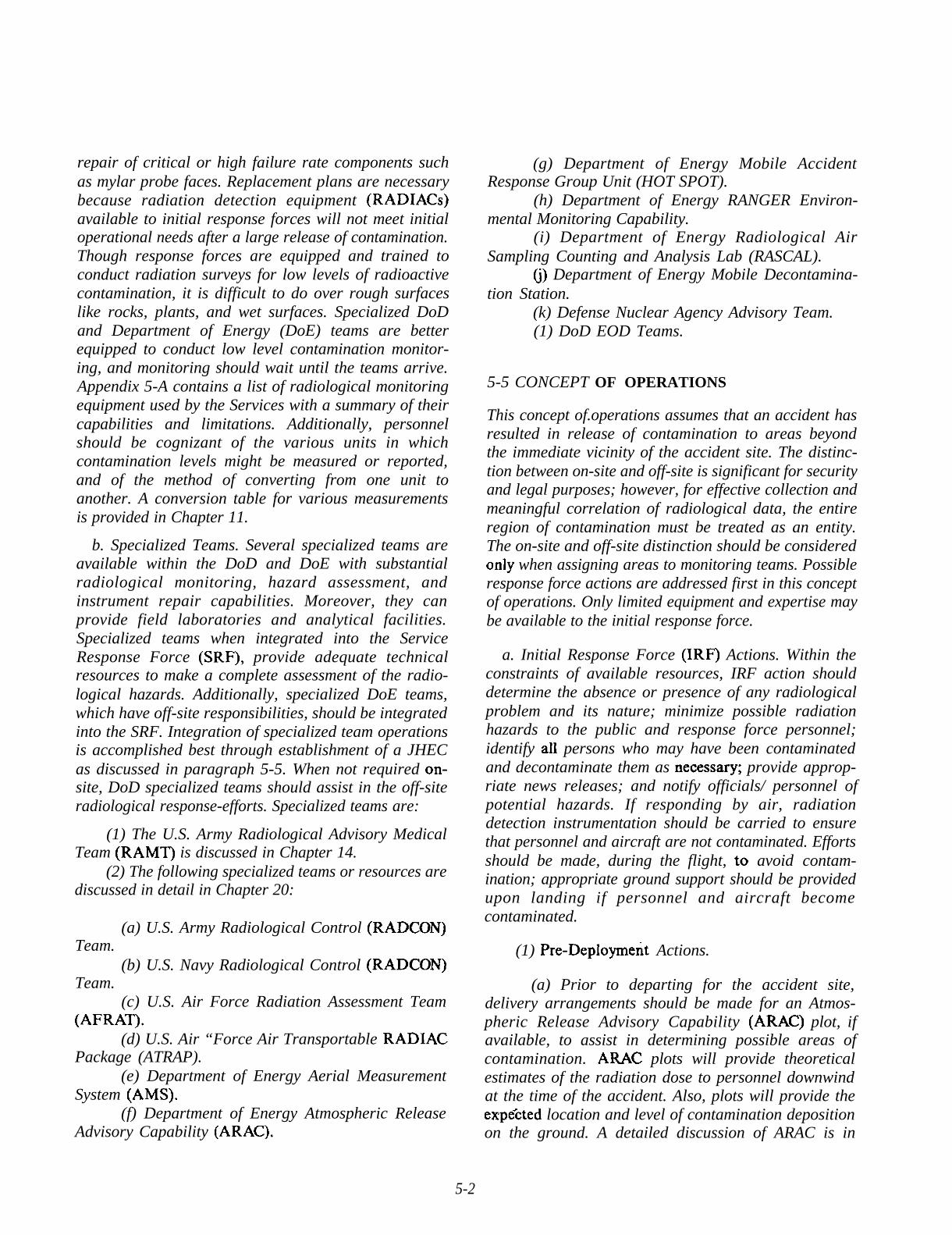
(1) Joint Hazard Evaluation Center. The JHEC isthe organization that oversees the on-site hazard andradiological data collection and assessment efforts. Byanalyzing data, it provides accurate and complete on-site hazard/ radiological recommendations. The JHECDirector should be knowledgeable about data on-siteand how to best employ the technical resources available.The recommended functional organtifation is shown atFigure 5-1.
(a) On-site collected data is processed throughand further distributed by the JHEC to the FRMAC.
(b) JHEC is the single control point for allhazard/ radiological on-site data and will provide themost rapid, accurate, and complete radiologicalinformation to both military and civil users. Dataprovided to the JHEC for analysis, correlation, andvalidation includes all hazard data on-site. After theinitial response, the JHEC establishes a radiation anddosimetry program which meets Service needs andrequirements for personnel working in or entering theon-site contamination control area. The JHEC should:
~. Collect radiological and hazard datarequired by the OSC on-site. Refer all unofficial requestsfor contamination information to the Joint InformationCenter (JIC).
~. Analyze and correlate all contaminationdata collected to identify inconsistencies which requirefurther investigation.
~. Provide contamination plots and otherrequired data to the OSC.
~, Review and correlate records from contam-ination control stations and other personnel processingpoints to ensure bioassays or other appropriate follow-up actions are taken.
~. Implement OSC’S health and safety stand-ards and monitor the safety procedures of all partic-ipating in weapon recovery operations.
~. Brief and train people not designatedpreviously as radiation workers who will be workingin” the contaminated area on personal protectiveequipment, hazards, and safety measures.
5-4
u!
(n
Senior Health JHEC Director FRMAC Liaison
Deputy Director OSC Liaisonand
Safety AdvisorWeapon Recovery
Chief of Staff LiaisonI
I●
SiteSecurity
RestorationLogistics
Administration
I I I I
“EzIzizlm. RAD Survey Teams . Contamination . Mobile Laboratories
. Ranger Control Station . Instrument Cali-
● Air Sampling . Industrial Hygiene bration and Repair
. Environmental . Industrial Safety . Equipment DECON
Sampling, etc. . Bioassy . Fixative Application● A M S . Personnel Decon
● Dosimetry. Waste Control● RAD SAFE SUPPOrt
(Radiography). Medical
Figure 5-1. Joint Harard Evaluation Center (JHEC) Functional Organization
PAssessmentand
Evaluation
. Data Control /QA
. Plotting
. Evaluation andAssessment
. Meteorology
. DispersionModeI (ARAC)
. Overview

(c) Consolidate all radiological assessmentinformation for on-site recovery operations and provideit to the OSC.
(d) When the National Defense Area (NDA) isdissolved, JHEC personnel and resources may beintegrated into FRMAC operations.
(2) Materials Sampling.
(a) Environmental Sampling.
~. Air sampling is conducted to determine ifairborne contamination is present. Also it provides abasis for estimating the radiation dose/exposure whichpeople without respiratory protection may have received.The reaction time to an accident combined with the timerequired to initiate air sampling will result in little orno data being obtained during the initial release ofcontamination. It is at this period that the highest levelsof contamination are expected. Later placement of asampler downwind the accident, per Appendix 5-B, willresult in a sample of airborne contamination. Airsampling will verify the resuspension hazard duringresponse and recovery operations. To achieve this,samplers should be placed downwind of the accident,dependent on wind velocity approximately 500 metersupwind, and at the contamination control station.
~. Soil, water, vegetation and swipe samplingof surfaces are required. Sampling should be initiatedin the contaminated area soon after the accident.Samples must be taken also at locations remote fromthe contaminated area to verify background readings.After this, samples are required periodically during therecovery process to determine radioactive materialmigration and dispersion and to substantiate decontam-ination/ recovery c(jmjletion. The JHEC will determineon-site sampling parameters, for example, samplelocation(s), method, frequency, volume of sample, andsize.
(b) Bioassay Program,
j. Bioassays methods estimate the amount ofradioactive material deposited in the body. The methodsuse either direct measurement, sensitive x-ray detectorsplaced over the chest (lung counting) and/ or otherorgans, or detection of radioactivity y in the excreta (nasalmucous, feces or urine).
~, A bioassay program for all individuals isrecommended to determine if any internal dose wasreceived, and to assure those who did not receive a dosethat their health was not impaired. Implementation ofa bioassay program and the documented results will be
important in the equitable settlement of any legal actionsthat may occur in the years following a nuclear weaponaccident. Personnel monitoring and bioassay programsare discussed in this paragraph and bioassay techniquesin Chapter 8.
(3) Work Force Protection. Standard radiationaccident and incident response procedures provideguidance for personnel protection during the first fewdays. As conditions stabilize, regulations governing workin radiation areas should be implemented. Considerationmust be given to participating organizations or Servicesdosage calculation methods and previous dosages as longas their procedures do not jeopardize health and safety,or unduly impair operations. The JHEC is responsiblefor implementing the OSC’S health and safety standardsand monitoring closely the safety procedures of all par-ticipating organizations. Personnel entering thecontaminated areas, if not trained to work in a radiationenvironment,’ should be given specific guidance.
(4) Radiological Surveys. Radiological surveys andother radiological data are required by the OSC andcivil authorities/ officials to identify actions to minimizehazards to the response force and the public. Site charac-terization and decontamination, and restorationplanning will also need this information. Radiologicalsurvey and data requirements must be given to theFRMAC for implementation to meet this requirementin an expeditious manner. Prior to extensive surveyinitiation, the following must be completed: selectappropriate detection equipment, calibrate instruments,and determine the background readings. Surveys includeNDA perimeter, area, and resource/facility surveys. Thesurvey results are complicated by sensitivity y/ fragilit y of.equipment, background readings, and the age of the
fissile materials. The survey process can require daysto weeks to compIete. Survey procedures are locatedin Appendix 5-D and forms are at Appendix 5-E.
(5) Radiological Advisory to the JIC. All publicrelease of information will be processed by DoD “Directive 5230.16, reference (b), and made through theJIC. Public interest in the actual or perceived radiologicalhazard resulting from a nuclear weapon accident willproduce intense media concern and public scrutiny ofresponse operations. The JIC requires assistance fromthe JHEC and FRMAC in preparing press releases tominimize and allay these concerns. Any portion of thepublic which may have been advised to take precau-tionary measures will seek clear, understandableexplanations of methods to protect their health andproperty. The public must be provided informationthrough the JIC and the Community Emergency ActionTeam (CEAT) explaining all real hazards, in terms which
5-6
recognize the populace’s knowledge level and under-standing of radiation and its effects.
(6) Fixing of Contaminants. Fixatives maybe usedto reduce resuspension and the spread of contamination.If water is readily available, it may be used as a temporaryfixative to reduce resuspension. Other more permanentfixatives may be used to reduce the spread ofcontamination by resuspension and run-off from highlycontaminated areas. The use of fixatives in areas of lowlevel contamination is usually inappropriate. Fixativesmay enhance or hinder decontamination and restorationoperations, and affect radiation survey procedures. TheDoE ARG can provide information on the advantagesand disadvantages of different types of fiiatives andmethods of application. They should be consulted priorto application of permanent fixatives.
(7) Recovery/ Restoration,
(a) Recovery. This activity includes the initialreconnaissance, the render safe procedures, hazardremoval, and disposition of the weapons and compo-nents. The two-person rule must be enforced strictlywhen working with nuclear weapons. In the early stagesof accident response, following all of the requiredsecurity measures may be difficult. However, the OSCshould implement necessary security procedures as soonas possible. The initial entry will determine thepreliminary weapon(s) status and hazards in the area.In the process of determining the weapon condition,search may be required to find the weapon(s). The OSCdirects the initiation of the render safe procedures. TheEOD team advises the OSC of the safest and mostreliable means for neutralizing weapon hazards.
(b) Sitey Restoration. Procedures/methods toreturn the accident scene to a technically achievable andfinancially acceptable condition begins early in theresponse effort. Site restoration becomes a major issueafter classitled information, weapons, weapon debris,and other hazards are removed. Several factors havesignificant influence on site restoration decisions andprocedures, such as size of the contaminated area,topographical, geological, hydrological, meteorologicaland demographic information. Other important aspectsare utilization of the area and civil authorities/officialsprerogatives for the area. Restoration will include thosemeasures to remove or neutralize the contamination.
(8) Disposal of Contaminated Waste. Contam-ination control staticm operations and JHEC fieldlaboratory operations creates considerable quantities ofcontaminated waste. Provisions, are required therefore,to store this waste temporarily in the contaminated area
.
until it can be moved to a disposal site. Procedures forthe disposal of contaminated waste are addressed as partof site restoration in Chapter 19.
(9) Logistics Support for Recovery/ RadiologicalOperations. Radiological response assets arrive withsufficient supplies to last a few days. High use itemswhich soon require resupply include hundreds of setsof anti-contamination clothing each day, two-inchmasking or duct tape, varied sizes of polyethylene bags,marking tape for contaminated materials, and respiratorfilters. Anti-contamination clothing may be launderedin special laundry facilities (discussed in Appendix 17-A) and reused. The turnaround time, when established,determines the approximate amount of anti-contamination clothing required. Close liaison will berequired between the JHEC and the SRF supply officer.
c. Radiological Hazards. The primary radiologicalhazard associated with a nuclear weapon accident is fromthe fissile material, particularly the alpha emitters.Sufficient quantities of beta/gamma emitters to posea significant health problem will not normally be presentat a nuclear weapon accident.
(1) Radiological Hazard Assessment. From flheoutset, concern exists about the potential health hazardto the general public, particularly by those residing nearthe accident site. Consideration of possible radiationexposures is the primary method of estimating thepotential health hazard. If no beta/ gamma radiation ispresent, the primary risk is inhalation of alpha emitterswhich may cause a long term increase in the probabilityof radiation related diseases. Initial hazard assessmentswill, of necessity, be based on limited information,assumptions, and worst case projections of possibleradiation doses received. Atmospheric Release AdvisoryCapability (ARAC), described in Appendix 5-C,provides a theoretical projection of the maximuminternal radiation dose people may have received ifoutdoors without respiratory protection from the timeof release to the effective time of the ARAC plot.Exposure to resuspended contaminants normally resultsin doses which are a small fraction of that dose whichwould be received from exposure to the initial releasefor the same time period. Contamination released bythe accident should not normally affect the safety ofpublic water systems with adequate water treatmentcapability.
(2) Reduction of Public Exposure. The hazardassessment must be followed quickly by recommendedprecautionary and safety measures to protect the publicfrom exposure. To control and minimize exposure,radioactive contaminants must be prevented from
5-7

entering the body and confined to specific geographicareas so that the contamination can be removedsystematically. Methods for reducing the exposure tothe public should be implemented by, or through, civilauthorities/ officials. Although political and possiblyinternational issues are likely to be involved, the ultimatedecisions on measures to be taken should be made basedon health and safety considerations.
(a) The initial response force may need to advisecivil authorities/ officials of recommended actions andprovide technical assistance until appropriate civilianassets arrive. When contamination has been released,or when probable cause exists to believe that contam-ination was released, the implementation of precaution-ary measures to reduce exposure to radiation orcontamination are appropriate, even though the serviceresponse force personnel may not arrive for some time.
(b) Protective measures include:
~. Establishing a contamination control area.This operation requires identifying people in the areaat the time of the accident/incident or and restrictingaccess to the area. Any vehicles or people exiting thearea should be identified and directed to go to a moni-toring point immediately.
~. Sheltering. Sheltering is used to minimizeexposure to the initial rdease of contamination as itmoves downwind, and to minimize exposure toresuspended contamination prior to an evacuation. Shel-tering is implemented by advising the people to seekshelter and the procedures to follow. The effectivenessof sheltering depends on following the proceduresprovided.
j. Evacuation. Contaminated areas must bedefined and an evacuation procedure developed andimplemented by civil authorities. Civil authorities willbe responsible for the evacuation but may requireradiological advice and assistance. Immediate evacua-tion of downwind personnel should be discouraged sincethe probability of inhalation of contaminants mayincrease. Explosive or toxic materials may present animmediate hazard to people near the accident site andimmediate evacuation would then be required.
~. Fixing Areas of High Contamination. Areasof high contamination must be controlled to preventspread by resuspension, water run-off, or movement ofpersonnel. Although fixing of contamination is part ofthe site restoration process, some fixing procedures maybe necessary long before site restoration plans areimplemented.
d. Respiratory and Whole Body Protection. Protec-tion of the general public, response force members, and
workers in the accident area from exposure throughinhalation is extremely important. Refer to Appendix5-D for additional guidance.
e. Radiation Surveys. Extensive radiation surveys willbe required to identify and characterize the area so thatdecontamination and restoration plans may be deve-loped and the results evaluated. Determining thatcontamination was released by the accident is veryimportant, if release occurred, priority must be givento the actions to identify and minimize the hazards topeople. These actions are included in Appendix 5-E.
f. Site Restoration. Site restoration involves negotiat-ing cleanup levels and fixing or removing contamination.The removal is most time consuming and requires anextensive workload to collect, remove, decontaminate,if appropriate, and replace the top soil. Monitoring isrequired during the removal process to verify thatcleanup has been achieved.
g. Verification. The decontamination effectivenesswill be verified by remonitoring/ resurveying the accidentscene to determine that the cleanup levels are achieved.
h. Protective Action Recommendations (PARs) andre-entry recommendations (RERs) provide appropriateprotective action and re-entry recommendations to thepublic. The PARs and RERs will have been coordinated/reviewed by the cognizant federal authority (DoD) andresponsible civilian authorities/ officials. The PARs andRERs will consider Protective Action Guides issued byEPA and state agencies. In an accident, PARs for initialnotification or evacuation would likely not be preparedformally. The notification in the accident area wouldoccur via visual means or word-of-mouth. Evacuationof approximately a 600 meter disaster cordon mightoccur automatically or at the direction of civilian lawenforcement personnel. A PAR for a controlledevacuation could be formalized in anticipation of asubsequent release of hazardous materials or radioactivecontamination. The PAR/ RER format may include, asa minimum; problem, discussion, action, coordinationand approval sections (the format should be site andsituation specific). A sample PAR for controlledevacuation is found on the next page.
5-6 ACCIDENT RESPONSE PLAN ANNEX
Procedures and information appropriate for inclusionin the’ Radiological Hazard Safety annex to the accidentresponse plan include
5-8

Major Accident
Protective Action Recommendation
for
at (location
Issued by:
Problem: An accident involving missile system re-entry vehicle occurred at (Time,date and location). Maintenance technicians have experienced complications in removing the missile secondstage from the missile launch facility.
. Discussion: It is possible, though highly improbable, that the second stage could explode. In the unlikelyevent of an explosion, debris could be thrown yards/ meters. As a result, an evacuation of (outlinethe specific area) has been ordered by Civilian Authority Office,
Action: With the possibility of the explosion of the missile second stage during removal operations, thefollowing area will be evacuated. (Indicate the specific area to be vacated and a schedule indicating evacuationstart, completion, verification of evacuation, maintenance work start, work completion and return to the area).Note: All personnel are required to sign in at a specific location(s) during evacuation to help local lawenforcement/ SRF personnel verify that all personnel are out of the area prior to maintenance start. A holdingarea, for example, YMCA, gymnasium, or school may be a temporary holding area for evacuees. Also, theevacuees could be released for shopping or other activities outside the area. Upon successful completion ofmaintenance, the personnel would return to their houses/businesses.
Note: Release of this “Protective Action Recommendation” cannot precede confirmation of the presenceof a nuclear weapon by the OSC and should b< coordinated with local officials and PAO priorto release.
5-9

a. A description of the JHEC organization andresponsibilities.
b. Procedures for operation of the JHEC.
c. Procedures for establishing and maintaining thecontamination control line.
d. Procedures for ensuring that all indigenouspersonnel possibly exposed to contamination areidentified, screened, and treated. This function willbecome DoE and/ or civilian responsibility as timeprogresses.
e. Guidelines for determining radiation survey anddecontamination priorities.
f. Procedures for ensuring that response forcepersonnel working in the contaminated area are properlyprotected.
g. Procedures for recording and maintaining pertinentdata for the radiological safety of response forcepersonnel.
h. Procedures for recording, correlating, and plottingthe results of radiological surveys and data collectioninstrumentation (for example, air samplers).
i. Procedures for JHEC and FRMAC interfacing.
j. Procedures for JHEC incorporation into theFRMAC.
5-1o

DoD 51 OO.52-M
APPENDIX 5-A
Instrument
RADIOLOGICAL MONITORING EQUIPMENT
DOSIMETERS
Self Reading IonizationChamber Dosimeter “
Non-Self ReadingIonization Chamber 0.Dosimeter
Film Badge
ThermoluminescentDosimeter (TLD)
Capability/Limitations
Reusable device for measuring exposure to X- and/or gamma radiation.Limitations: False positive readings due to charge leakage and sensitivity tomechanical shock.
<,Same capabilities, limitations, and use aq Self-Reading Ionization ChamberDosimeter. Additional Limitations: Requires reading device.
Provides measurement and permanent record of beta and gamma radiationdoses over wide dosage range. Special neutron films are available. Ten (10)percent dose accuracy depending on quality control during development.Limitations: Sensitive to light, humidity, aging, and exposure to x-radiation.Delay between exposure and dose reading due to processing time.
The TLD (thermoluminescent dosimeter) provides measurement of gammaradiation dose equivalents up to 10000 rem. Accurate to within a factor oftwo when the energy of the neutrons is unknown. Limitations: after longperiods of exposure (* mrem), damaged or bent cards delay processing, staticelectric discharge causes spurious readings, and temperatures >115° degreesF reduce sensitivity. Delay between exposure and dose reading due to centralprocessing of TLDs.
.“
TRITHJM DETECTION INSTRUMENTS
Instrument Capability Scale Indicator
T-446 Tritium o to 10 pCi/ m3
Portable, tritium detector; automatic scale switching; and trickle charger for nickel cadmium F cells. With adapterkit, has urinalysis capability for tritium with 5-minute response. Weighs 22 pounds. Has particulate filter withfilters down to 0.3 microns (eliminates sensitivity to smoke and paint fumes).
T-290A Tritium 0 to 1,0003 ranges
Portable, air sampler; and detects presence of radioactive gas. Weighs 17 pounds
flCi/m3Concentration of gasin chamber
Must be rezeroed after 15 minutesof operation and once an hour thereafter. Sensitive to smoke and paint fumes. External battery pack is availablefor cold weather operations.
5-A- I

-“
TRITIUM DETECTION INSTRUMENTS (CONTINUED)
Instrument Capability S c a l e Indicator
Ic-T2/PAB(M) Tritium . 0 to 100,000 flCi/mJ3 ranges
Portable air monitor designed to detect gaseous radioactivity in ambient air. Alarm sounds at preset meter readings.
AN/ PDR-74 Tritium O to lOOK pCi/ m3
3 ranges
The portable RADIAC set contains an IM-246 light weight tritium air monitor to detect airborne radioactive gases.Also, the instrument is calibrated directly in terms of tritium activity but may also be used to detect other radiogasesor to monitor gamma radiation if appropriate calibration factors are applied to the meter reading. The instrumentis battery operated (D cells) and has an audible alarm when radioactivity exceeds a preset level.
ALPHA SURVEY INSTRUMENTS
Instrument Capability Type Scale Indicator
AN/ PDR-56 Alpha Scintillation O to 1,000K CPM/ 17 cmz4 ianges
A small auxiliary probe provided for monitoring irregular objects. Mylar probe face is extremely fragile and apuncture disables the instrument until repaired. Accompanying x-ray probe is calibrated for 17 KeV with associatedmeter scale from O-10 mg/ m2 in four ranges.
AN/ PDR-60 Alpha Scintillation O to 2,000K . CPM/ 60 cmz(PAC-ISAGA) G a m m a G-M tube 4 ranges R/ hr
Capable of measuring gamma utilizing the 2R range. Intermediate and high-range alpha survey; intermediate gammarange; weighs eight pounds. May use plutonium gamma detector (pG-l) for inclement weather. Mylar probe faceis delicate and puncture disables alpha monitor capability until repaired; gamma detector will continue to function.AN/ PDR-60 or PAC-IS has identical alpha capabilities but does not have the gamma detection capability.
PRM-5 Alpha Scintillation O to 500K CPM4 ranges
Portable, high and low-range instrument, for detecting alpha contamination through measurement of the associatedX-rays and low energy gamma radiation. This exercise is done with probes with separate ranges. PG-2 probe,10 to 100 KeV and FIDLER probe O to 100 Kev. Weighs 5.4 pounds. The FIDLER probe has significantly greatersensitivity than other probes. Very few units other than specialized Service and DoE teams possess the FIDLER.PRM-5 probes are effective in inclement weather and are much less subject to damage during field use than otheralpha meter probes.
5-A-2

ALPHA SURVEY INSTRUMENTS (CONTINUED)
Instrument Capability Type Scale Indicator
Ludlum Alpha/ Beta/ Gamma Scintillation O to 400K cpmModel 3 G-M Tube O to 200mR/h mR/ h
Portable, high and low range analyzer for detecting alpha, beta and gamma emissions. The Model 3 is an electronicpackage similar in operation and function to the PDR-60 analyzer. Probe 43-5 detects alpha via scintillation, theprobe surface area is 50 cmz. Probe 44-6 (Hot Dog) uses a G-M tube to detect beta and gamma. Probe 44-9(Pancake Probe) detects low energy gamma, O to 200 mR/h.
Ludlum Alpha Scintillation O to 500K cpmModel 2220 4 ranges
The Model 2220 is an alpha detector electronics package that has a liquid crystal display and integral digital readout.The unit weighs 3.5 pounds and has an adjustable high voltage and adjustable lower level discrimination feature.
VIOLINIST II - HIVOLT-PREAMP FIDLER INSTRUMENT SET. This instrument set includes the FIDLER,high voltage power supply and preamplifier and the Violinist H. The Violinist 11 consists of a battery operated256 multi-channel analyzer and a preprogrammed microprocessor. This instrument set, when calibrated appropriately,measures and determines surface contamination levels of plutonium and amencum-241 in pCi/ m2.
RANGER. The instrument set includes the FIDLER/ Violinist 11 and a position determining system. The microwaveranging system uses a base station, fixed repeaters and mobile units. The mobile units transmit FIDLER radiationdata to the repeaters and base station. The microprocessor develops in near real time radiation readings, contaminationdensity, and isopleths. The microwave ranging system is limited to near line-of-sight. Dense vegetation, building,and hilly terrain may effect the ranging signal.
BETA/GAMMA SURVEY INSTRUMENTS
Instrument Capability Type Scale Indicator
AN/ PDR-27 Measures gamma on Geiger-Muller o to 500 mR/hall scales. Detects beta 4 rangestwo lower scales.
Low range; weighs eight pounds; beta window on probe to detect beta, and suitable for personnel monitoring.May saturate and read zero in high-radiation fields (over 1,000 r/ hr).
AN/ PDR-43 Measures gamma. Geiger-Muller o to 500Detects beta on 3 rangesall scales.
High range; weighs 4.5 pounds, and will not saturate in high-radiation area.CO-60 may have inaccuracies greater than 20 percent.
IM-174/PD Gamma Integrating 0.1 to 10ion chamber o to 500
High range; weighs 3 pounds; logarithmic scale, and temperature sensitive.
Ludlum Gamma Scintillation O to 5 mrl hrModel 19
5-A-3
R/h
Readings in gamma fields other than
R/h
uR)h

DoD 51 OO.52-M
-’
APPENDIX 5-A. I
RADIATION DETECTION AND MEASUREMENT
(The Inference of Piutonium Contamination using the FIDLER)
5-A.1-1 OVERVIEW
. .a. Quantltattve measurements of radioactive contam-
ination m the field are extremely difficult. Particleshaving short ranges, such as alpha and low energy betaradiation, are significantly and incalculably affected byminute amounts of overburden, for example, dust orprecipitation. Therefore, detection rather than measure-ment is a more realistic goal for alpha-beta surveys. Morepenetrating radiations, such as gamma and higher energyx-rays, are effected less by such overburden; however,these elements require special attention to fieldcalibration techniques in order to convert meter readingsto contamination estimates.
b. Field survey of uranium is best accomplishedthrough measurement of x-rays in the 60-80 thousandelectron volt (keV) range emitted by uranium isotopesand daughters. For plutonium, the best technique is todetect the accompanying contaminant Am-24 1, whichemits a strong 60 keV gamma-ray. Knowing the originalassay and the age of the weapon, the ratio of plutoniumto americium can be calculated accurately and thus thetotal plutonium contamination determined.
c. Many of the factors which cannot be controlledin a field environment can be managed in a mobilelaboratory which can be brought to an accident/ incidentsite. Typically, the capabilities include gamma spectros-copy, low background counting for very thin alpha- andbeta-emitting samples and liquid scintillation countersfor extremely low energy beta emitters such as tritium.
5-A.1-2 GENERAL
a. Scope. This appendix provides detailed informa-tion from LLNL Report M-161 and Steven G. Hamann,references (o) and (p) on the instrumentation andassociated techniques used to perform radiologicalmonitoring at an incident/accident involving the releaseof radioactive material. This appendix is not intended
to serve as a “user’s manual” for the various instruments.However, it includes sufficient detail to provide anunderstanding of the limitations of field measurementtechniques and thus provides for proper application andthe use of techniques in case of an emergency. Forcompleteness, some elementary characteristics ofdifferent kinds of radiation are included. Throughoutthis appendix the word “radiation” will refer only tonuclear radiations found at a nuclear incident/accident.
b. Detection versus Measurement.
(1) Nuclear radiation cannot be detected easily.Thus, radiation detection is always a multi-step, highlyindirect process. For example, in a scintillation detector,incident radiation excites a floresc.ent material that de-excites by emitting photons of light. The light is focusedonto the photocathode of a photomultiplier tube thattriggers an electron avalanche. The electron showerproduces an electrical pulse which activates a meter readby the operator. Not surprisingly, the quantitativerelationship between the amount of radiation actuallyemitted and the reading on the meter is a complexfunction of many factors. Since control of those factorscan only be accomplished well within a laboratory, onlyin a laboratory setting can true measurements be made.
(2) On the other hand, detection is the qualitativedetermination that radioactivity is or is not present.Although the evaluation of minimum levels of detec-tability is a considerable quantitative challenge forinstrumentation engineers, the task of determiningwhether a meter records anything is considered mucheasier than the quantitative interpretation of thatreading.
(3) The above discussion suggests that the sameequipment can be used for either detection or measure-ment. In fact generally, detectors have meters from whichnumbers can be extracted. However, to the extent thatthe user is unable to control factors which influencethe readings, those readings must be recognized asindications of the presents of activity (detection) onlyand not measurements.
5-A. I-1
(4) In the discussions that follow, personnel mu~tbe aware of the limitations imposed by field conditionsand their implications on the meaning of readings taken.Therefore, instructions are careful to indicate the extentto which various instruments may be used as measure-ment devices or can be used only as detectors.
5-A.1-3 TYPES OF RADIATION
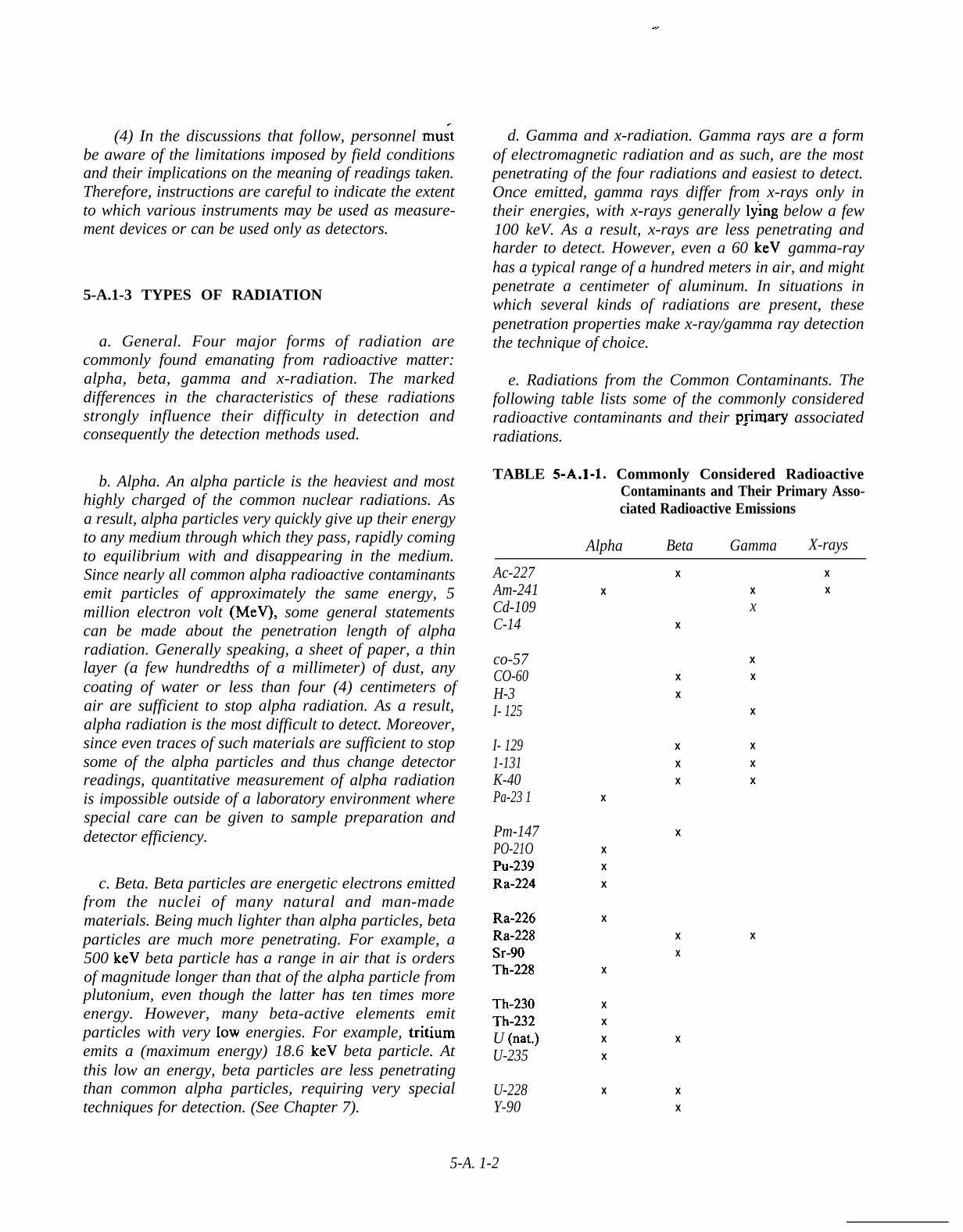
a. General. Four major forms of radiation arecommonly found emanating from radioactive matter:alpha, beta, gamma and x-radiation. The markeddifferences in the characteristics of these radiationsstrongly influence their difficulty in detection andconsequently the detection methods used.
b. Alpha. An alpha particle is the heaviest and mosthighly charged of the common nuclear radiations. Asa result, alpha particles very quickly give up their energyto any medium through which they pass, rapidly comingto equilibrium with and disappearing in the medium.Since nearly all common alpha radioactive contaminantsemit particles of approximately the same energy, 5million electron volt (MeV), some general statementscan be made about the penetration length of alpharadiation. Generally speaking, a sheet of paper, a thinlayer (a few hundredths of a millimeter) of dust, anycoating of water or less than four (4) centimeters ofair are sufficient to stop alpha radiation. As a result,alpha radiation is the most difficult to detect. Moreover,since even traces of such materials are sufficient to stopsome of the alpha particles and thus change detectorreadings, quantitative measurement of alpha radiationis impossible outside of a laboratory environment wherespecial care can be given to sample preparation anddetector efficiency.
c. Beta. Beta particles are energetic electrons emittedfrom the nuclei of many natural and man-madematerials. Being much lighter than alpha particles, betaparticles are much more penetrating. For example, a500 keV beta particle has a range in air that is ordersof magnitude longer than that of the alpha particle fromplutonium, even though the latter has ten times moreenergy. However, many beta-active elements emitparticles with very low energies. For example, tritiumemits a (maximum energy) 18.6 keV beta particle. Atthis low an energy, beta particles are less penetratingthan common alpha particles, requiring very specialtechniques for detection. (See Chapter 7).
d. Gamma and x-radiation. Gamma rays are a formof electromagnetic radiation and as such, are the mostpenetrating of the four radiations and easiest to detect.Once emitted, gamma rays differ from x-rays only intheir energies, with x-rays generally ly”ing below a few100 keV. As a result, x-rays are less penetrating andharder to detect. However, even a 60 keV gamma-rayhas a typical range of a hundred meters in air, and mightpenetrate a centimeter of aluminum. In situations inwhich several kinds of radiations are present, thesepenetration properties make x-ray/gamma ray detectionthe technique of choice.
e. Radiations from the Common Contaminants. Thefollowing table lists some of the commonly consideredradioactive contaminants and their p@nary associatedradiations.
TABLE 5-A.1-1. Commonly Considered RadioactiveContaminants and Their Primary Asso-ciated Radioactive Emissions
Alpha Beta Gamma X-rays
Ac-227Am-241Cd-109C-14
co-57CO-60H-3I- 125
I- 1291-131K-40Pa-23 1
Pm-147PO-21OPu-239Ra-224
Ra-226Ra-228Sr-90Th-228
Th-230Th-232U (nat.)U-235
U-228Y-90
xx
x
xxx
x
xx
xxx
x
xx xx
xx
x
xxx
xx xx
x
xxxx
x
x
xx
5-A. 1-2

.’
5-A.1-4 ALPHA DETECTION
a. Because of the extremely low penetration of alphaparticles, special techniques must be employed to allowthe particles to enter the active region of a detector.In the most common field instruments (AN/ PDR-56and -60), an extremely thin piece of aluminized mylarfilm is used on the face of the detector probe to covera thin layer of fluorescent material. Energy attenuationof the incident alpha radiation by the mylar is estimatedto be less than ten (10) percent. However, use of thisfilm makes the detector extremely fragile. Thus, contactwith literally any hard object, such as a blade of hardgrass, can puncture the film allowing ambient light toenter the detection region and overwhelm the photo-multiplier and meter. (Even sudden temperature changeshave been shown to introduce stresses that can destroya film). In addition, contact with a contaminated itemcould transfer contamination onto the detector. Thus,monitoring techniques must be used which keep thedetector from contacting any surface. However, recallthat the range of the alpha radiation is less than four(4) centimeters in air. This requirement to be withina few centimeters of monitored locations without evertouching one makes use of such detectors impracticalexcept for special, controlled situations (for example,monitoring of individuals at the hotline or air samplerfilters).
b. As discussed above, the sensitivity (minimumdetectability) of an alpha detector is not dictated bythe ability of the active region of the detector to respondto the passage of an alpha particle; counting efficiencyfor alpha detectors is 25-60 percent of the alpha particlesfrom a distributed source that reach the detector probe.Fortunately, -alpha detectors” in good repair normallyhave a fairly low background: there are few counts fromcosmic and other spurious radiation sources and theelimination of most electronic noise is easy with currentstate-of-the-art instruments. As a result, count rates inthe order of a few hundred counts per minute are easilydetectable on instruments such as the AN/ PDR-60.However, the detectability is dominated by the abilityof the alpha particles to get into the active region ofthe detector, which depends upon such factors asoverburden (amount of dust and/or moisture lyingbetween the alpha emitters and the detector), and theproximity of the detector to the emitters.
c. In demonstrations conducted in the laboratory, asealed alpha source (Am-24 1) was monitored with a wellmaintained AN/ PDR-60 alpha probe and meter. Dustand water were sprinkled onto the source and changes
noted. It was found that a drop of water, a heavy pieceof lint or a single thickness of tissue paper totallyeliminated all readings. A light spray of water,comparable to a light dew, reduced readings by 40-50percent. A layer of dust that was just visible on theshiny source had minimal effect on the count rate;however, a dust level that was only thick enough toshow finger tracks reduced readings by 25 percent. Thesesimple demonstrations reinforced the knowledge thatdetection of alpha particles in any but the most idealsituations is most problematical. The leaching or settlingof contaminants into a grassy area or the dust stirredup by vehicular traffic on paved areas will significantlydecrease or eliminate alpha detection.
5-A.1-5 BETA/GAMMA DET~CTION
a. Gamma rays and high energy (>1 MeV) betaparticles are highly penetrating radiations. As a result,the major problems listed for alpha detection do notapply. Furthermore, at the energies of concern in nuclearweapon accidents/ incidents, detection efficiency formost detectors is relatively high. Thus, beta/gammadetection is relatively easy.
b. From a detection standpoint, unfortunately, highenergy beta and gamma radiation are not produced inthe most likely radioactive contaminants (for example,Plutonium, Uranium or Tritium). Rather, the majorpotential source of beta/gamma emitters is from fissionproduct radioelements which could be produced in theextremely unlikely event of a partial nuclear yield. Beta/gamma detection, therefore, has no quantitative use indetermining the extent of plutonium or uraniumcontamination, but is used as a safety precaution todetermine any areas containing hazardous fissionproducts.
c. Common gamma detectors are scintillationdetectors (using scintillation media different from thatdescribed above for alpha detection) or gas ionizationtype detectors (ion chambers, proportional counters orGeiger counters). In either case, the high penetrabilityof the radiation allows the detector to have reasonablyheavy aluminum, beryllium or plastic windows and tobe carried at a 0.5-1 .Om height. Dimensions of the activeregion of the detector (for example, the thickness ofa scintillation crystal) can be made larger to increasesensitivity. Because the detection efficiencies arereasonably insensitive to energies in the energy regionsof interest, the detectors can be calibrated in terms ofdosage (rads or rem), rather than in terms of activity:
5-A.1-3

-’
this practice reflects the common use for beta/ gammadetectors
d. Typical of a beta/gamma detector is the LudlumModel 3 with a Ludlum 44-9 “pancake” (Geiger-Muller)probe. Minimum detectability for such a detector is aradiation field that produces readings two to three timesgreater than the background (no-contaminant, naturalradiation plus electronic noise) reading. Customarily,this corresponds to a few hundredths of a millirem perhour.
5-A.1-6 X-RAY DETECTION
a. For low energy (17-100 keV) x-rays, the scintillationdetector is again the instrument of choice. Windowthickness is again a factor, though not as much as withalpha particles. For example, the half-thickness forabsorption of 17 keV x-rays in aluminum is 0.4 mmand in air is about four meters. These factors increaserapidly with energy. For 60 keV x-rays, the distancesbecome 2.5 cm and 190 m respectively. Thus, for x-rays above 15 keV, an x-ray detector can be held ata comfortable height (0.5 m) above the contaminatedsurface.
b. The size of an electronic pulse produced by anx-ray in a scintillation-type detector is proportional tothe energy of the x-ray. This has a most importantapplication, commonly called pulse-height discrimina-tion. Because of the relatively low (10s of keV) energyof the x-rays of interest, an x-ray detector and itselectronics must be quite sensitive. Unfortunately, sucha detector is sensitive also to the myriad of radiationsfrom natural sources and to common low-level electronic
Figure 5-A.1-1:
noise. The result is a deluge of signals that overwhelmthe pulses from sought-after x-rays. To remove theunwanted signals, circuitry is installed in the meter toignore all pulses whose size lies below a user-selectablelower level (threshold). In cases of high (natural)background, it is also useful to discard all pulses whosesize is greater than a user-selectable upper level. Theaccepted pulses, therefore, are only those from thedesired x-rays and that small amount of backgroundthat happens to fall in the same pulse-size region.
c. Unfortunately, pulse-height discrimination is notas “easy” as described above. In fact, the signals fromthe detection of identical x-rays will not be identicalin size; rather, a large number of such detections willproduce a distribution of pulse sizes which cluster abouta mean pulse size. If one sets the lower-level discriminate orslightly below and the upper level slightly above themean pulse size, “a large fraction of the desired pulseswill be eliminated, resulting in a significant decrease indetector response. However, setting the discriminatorlevels far from the mean will admit too muchbackground, thereby masking the true signals. See Figure5-A. 1-1. Thus, the setting of discriminator levels requiresa qualitative judgment which can significantly affect thereadings from a given contamination. Furthermore, sincethe width of the pulse size distribution depends in amost complicated way upon the condition and age ofthe detector, it is impossible to specify one setting forall similar instruments. Rather, techniques have beendeveloped to establish the sensitivity of a given detector,with its electronics, in a field environment. Thistechnique is described in the following section.
d. In spite of the above complications, the scintillationdetector remains the instrument of choice for detection
Photo Peak
}
‘Typical~Discriminator
Senings
Spectral Plot (Showing Normal Spread Of Pulses From A Mono-energetic Source Mixed With A Typical Background Spectrumand Indicating Typical Discriminator Settings).
5-A.14
-“
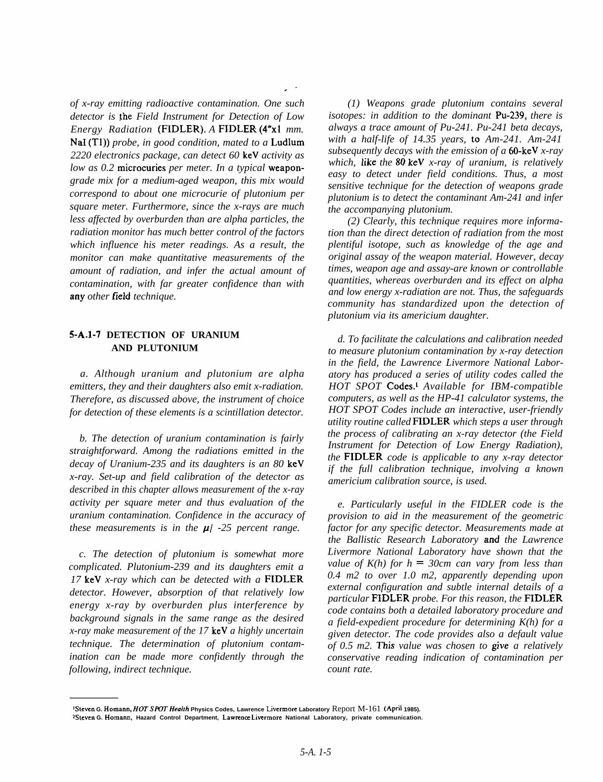
of x-ray emitting radioactive contamination. One suchdetector is !he Field Instrument for Detection of LowEnergy Radiation (FIDLER). A FIDLER (4*x1 mm.NaI (Tl)) probe, in good condition, mated to a Ludlum2220 electronics package, can detect 60 keV activity aslow as 0.2 microcuries per meter. In a typical weapon-grade mix for a medium-aged weapon, this mix wouldcorrespond to about one microcurie of plutonium persquare meter. Furthermore, since the x-rays are muchless affected by overburden than are alpha particles, theradiation monitor has much better control of the factorswhich influence his meter readings. As a result, themonitor can make quantitative measurements of theamount of radiation, and infer the actual amount ofcontamination, with far greater confidence than withany other field technique.
5-A.1-7 DETECTION OF URANIUMAND PLUTONIUM
a. Although uranium and plutonium are alphaemitters, they and their daughters also emit x-radiation.Therefore, as discussed above, the instrument of choicefor detection of these elements is a scintillation detector.
b. The detection of uranium contamination is fairlystraightforward. Among the radiations emitted in thedecay of Uranium-235 and its daughters is an 80 keVx-ray. Set-up and field calibration of the detector asdescribed in this chapter allows measurement of the x-rayactivity per square meter and thus evaluation of theuranium contamination. Confidence in the accuracy ofthese measurements is in the p/ -25 percent range.
c. The detection of plutonium is somewhat morecomplicated. Plutonium-239 and its daughters emit a17 keV x-ray which can be detected with a FIDLERdetector. However, absorption of that relatively lowenergy x-ray by overburden plus interference bybackground signals in the same range as the desiredx-ray make measurement of the 17 keV a highly uncertaintechnique. The determination of plutonium contam-ination can be made more confidently through thefollowing, indirect technique.
(1) Weapons grade plutonium contains severalisotopes: in addition to the dominant Pu-239, there isalways a trace amount of Pu-241. Pu-241 beta decays,with a half-life of 14.35 years, to Am-241. Am-241subsequently decays with the emission of a 60-keV x-raywhich, like the 80 keV x-ray of uranium, is relativelyeasy to detect under field conditions. Thus, a mostsensitive technique for the detection of weapons gradeplutonium is to detect the contaminant Am-241 and inferthe accompanying plutonium.
(2) Clearly, this technique requires more informa-tion than the direct detection of radiation from the mostplentiful isotope, such as knowledge of the age andoriginal assay of the weapon material. However, decaytimes, weapon age and assay-are known or controllablequantities, whereas overburden and its effect on alphaand low energy x-radiation are not. Thus, the safeguardscommunity has standardized upon the detection ofplutonium via its americium daughter.
d. To facilitate the calculations and calibration neededto measure plutonium contamination by x-ray detectionin the field, the Lawrence Livermore National Labor-atory has produced a series of utility codes called theHOT SPOT Codes.1 Available for IBM-compatiblecomputers, as well as the HP-41 calculator systems, theHOT SPOT Codes include an interactive, user-friendlyutility routine called FIDLER which steps a user throughthe process of calibrating an x-ray detector (the FieldInstrument for Detection of Low Energy Radiation),the FIDLER code is applicable to any x-ray detectorif the full calibration technique, involving a knownamericium calibration source, is used.
e. Particularly useful in the FIDLER code is theprovision to aid in the measurement of the geometricfactor for any specific detector. Measurements made atthe Ballistic Research Laboratory arid the LawrenceLivermore National Laboratory have shown that thevalue of K(h) for h = 30cm can vary from less than0.4 m2 to over 1.0 m2, apparently depending uponexternal configuration and subtle internal details of aparticular FIDLER probe. For this reason, the FIDLERcode contains both a detailed laboratory procedure anda field-expedient procedure for determining K(h) for agiven detector. The code provides also a default valueof 0.5 m2. This value was chosen to give a relativelyconservative reading indication of contamination percount rate.
lSteven G. Homann, HOT SJ?3T Health Physics Codes, Lawrence Lkermore Laboratory Report M-161 (April 1985).2Steven G. Homann, Hazard Control Department, Lawremx Ltvermore National Laboratory, private communication.
5-A. 1-5
-“
5-A.1-8 LABORATORY TECHNIQUES
As discussed above, laboratory procedures are necessaryto make quantitative measurements of radiationcontamination. For this reason, mobile laboratories areavailable within DoD and DoE for deployment to anaccident site. Although specific instrumentation willvary, the types of laboratory analyses fall into threecategories: gamma and x-ray spectroscopy, alpha-betacounting, and liquid scintillation.
a. Gamma and X-ray Spectroscopy. The major toolsinvolved in gamma and x-ray spectroscopy are areasonably high resolution gamma/ x-ray detector (suchas a GeLi or selectively high resolution NaI) and a multi-channel analyzer. With this equipment, it is possible toaccurately determine the energies of the gamma and x-radiation emitted by a contaminated sample. Generally,spectroscopic techniques are not used for absolutemeasurements of amount of contamination (for example,microcuries) in a sample. However, by adjusting for theenergy dependence of detection efficiencies and usingstandard spectral unfolding techniques, the relativeamounts of various isotopes present in the contaminantmay be determined accurately. Recalling the discussionsin the preceding sections, immediate application can beseen for such information: For example, spectroscopyallows determination of the relative abundance of Am-241 to Pu-239, resulting in accurate calibration of themost sensitive (FIDLER) survey techniques.
b. Alpha-Beta Counting.
(1) Another laboratory technique, alpha-betacounting, results in a reasonably accurate determinationof the absolute amount of contamination in a sample.Two types of counters are common and both are fairlysimple in principle. In one, a reasonably sensitive alpha-beta detector, such as a thin layer of ZnS mated toa photomultiplier tube, is mounted in a chamber thatis shielded to remove background radiation. A sample,made very thin to minimize self-absorption, is insertedinto the chamber under the detector. In some apparatus,air is evacuated from the chamber to eliminate airabsorption of the radiation. The count rate is thenmeasured. Knowing the geometry of the experiment
permits translating the count rate to an absoluteevaluation of sample activity.
(2) Another alpha-beta technique involves gas-floyproportional counters. In these devices, a sample isinserted ‘into the chamber of a proportional counter.Any emitted radiation causes ionization of the gas inthe counter which is electronically amplified andcounted.
(3) In both types of alpha-beta counter, the mostdifficult, sensitive part of the experiment is the samplepreparation. To achieve absolute measurements ofactivity, absorption of the radiation must be minimizedby the overburden caused by the sample itself.Techniques used include dissolution of the sample ontoa sample holder; evaporation of the solvent leaves avery thin, negligibly absorbing sample. Clearly,quantitative alpha-beta counting is a difficult, time-consuming process.
c. Liquid Scintillation.
(1) In a few cases, notably in the detection of betaradiation from tritium, the energy of the radiation isso low - and the resultant absorption is so high - thatsolid samples cannot be used for quantitative analysis.In these cases, dissolving the contaminant in ascintillating liquid may be possible. Glass vials of suchliquid can then be placed in a dark chamber and theresulting scintillation light pulses counted usingphotomultipliers.
(2) Again, the outstanding difficulty with thisprocess is in the sample preparation. Scintillation liquidsare extremely sensitive to most impurities which tendto quench the output of light pulses. As a result, themost common technique for liquid scintillation samplegathering is to wipe a fixed area (typically 100 squarecentimeters) of a hard surface in the contaminated areawith a small piece of cloth. The cloth can then beimmersed totally in scintillation liquid in such a waythat subsequent light emission will be visible to one ofthe photomultipliers in the analysis chamber. Alter-natively, the cloth can be replaced by a special plasticmaterial that dissoIves in scintillation liquid withoutsignificantly quenching light output. In either case, thetechnique works best when the contamination can begathered without large amounts of local dirt, oil, etc.
5-A. 1-6
DoD 51 OO.52-M
APPENDIX 5-B
ENVIRONMENTAL SAMPLING
5-B-1 GENERAL
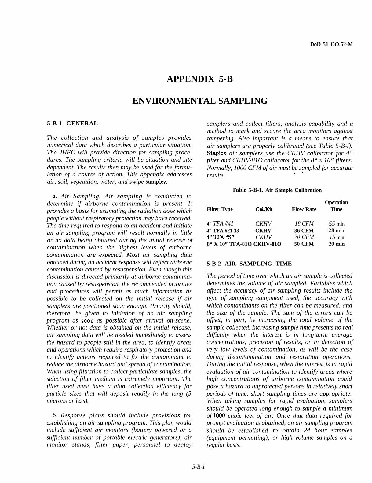
The collection and analysis of samples providesnumerical data which describes a particular situation.The JHEC will provide direction for sampling proce-dures. The sampling criteria will be situation and sitedependent. The results then may be used for the formu-lation of a course of action. This appendix addressesair, soil, vegetation, water, and swipe sampies.
a, Air Sampling. Air sampling is conducted todetermine if airborne contamination is present. Itprovides a basis for estimating the radiation dose whichpeople without respiratory protection may have received.The time required to respond to an accident and initiatean air sampling program will result normally in littleor no data being obtained during the initial release ofcontamination when the highest levels of airbornecontamination are expected. Most air sampling dataobtained during an accident response will reflect airbornecontamination caused by resuspension. Even though thisdiscussion is directed primarily at airborne contamina-tion caused by resuspension, the recommended prioritiesand procedures will permit as much information aspossible to be collected on the initial release if airsamplers are positioned soon enough. Priority should,therefore, be given to initiation of an air samplingprogram as soon as possible after arrival on-scene.Whether or not data is obtained on the initial release,air sampling data will be needed immediately to assessthe hazard to people still in the area, to identify areasand operations which require respiratory protection andto identify actions required to fix the contaminant toreduce the airborne hazard and spread of contamination.When using filtration to collect particulate samples, theselection of filter medium is extremely important. Thefilter used must have a high collection efficiency forparticle sizes that will deposit readily in the lung (5microns or less).
b, Response plans should include provisions forestablishing an air sampling program. This plan wouldinclude sufficient air monitors (battery powered or asufficient number of portable electric generators), airmonitor stands, filter paper, personnel to deploy
samplers and collect filters, analysis capability and amethod to mark and secure the area monitors againsttampering. Also important is a means to ensure thatair samplers are properly calibrated (see Table 5-B-l).Staplex air samplers use the CKHV calibrator for 4“filter and CKHV-81O calibrator for the 8“ x 10” filters.Normally, 1000 CFM of air must be sampled for accurateresults. x-
Table 5-B-1. Air Sample Calibration
OperationFilter Type Cal.Kit Flow Rate Time
4“ TFA #41 CKHV 18 CFM 55 min4“ TFA #21 33 CKHV 36 CFM 28 min49, TFA “S33 CKHV 70 CFM 15 min8“ X 10” TFA-81O CKHV-81O 50 CFM 20 min
5-B-2 AIR SAMPLING TIME
The period of time over which an air sample is collecteddetermines the volume of air sampled. Variables whichaffect the accuracy of air sampling results include thetype of sampling equipment used, the accuracy withwhich contaminants on the filter can be measured, andthe size of the sample. The sum of the errors can beoffset, in part, by increasing the total volume of thesample collected. Increasing sample time presents no realdifficulty when the interest is in long-term averageconcentrations, precision of results, or in detection ofvery low levels of contamination, as will be the caseduring decontamination and restoration operations.During the initial response, when the interest is in rapidevaluation of air contamination to identify areas wherehigh concentrations of airborne contamination couldpose a hazard to unprotected persons in relatively shortperiods of time, short sampling times are appropriate.When taking samples for rapid evaluation, samplersshould be operated long enough to sample a minimumof 1000 cubic feet of air. Once that data required forprompt evaluation is obtained, an air sampling programshould be established(equipment permitting),regular basis.
toor
obtain 24 hour sampleshigh volume samples on a
5-B-1

5-B-3 AIR SAMPLER PLACEMENT,
Sampler positioning is directed toward the first 24-48hours following an accident, or until an air samplingprogram tailored to the specific situation can beimplemented. During this period the number of airsamplers available will be limited, and should be placedto obtain the maximum amount of information possible.
a. The amount of airborne contamination caused byresuspension will vary from location to location as afunction of surface type, physical activity, surface windpatterns, and the level of contamination on the ground.Recommendations on the initial placement of samplersassume that the mix of surface t ypes is relatively constantthroughout the area, that air samplers will be placedto minimize any localized wind effects, and that thelocation of physical activity in the area (for example,response actions or evacuation) will be known andcontrolled. The main variables in determining theamount of airborne contamination will be groundcontamination levels and wind speed. To provide thequickest and most accurate estimate of the maximumconcentrations of airborne contamination, priorityshould therefore be given to placing an air sampler at,
or near, the most highly contaminated area which isaccessible.
b. Figure 5-B-1 shows the recommended placementof air samplers. The sampler number indicates thepriority which should be given to placement. All airsampling locations should “be marked with a uniquenumber or symbol on a stake, so that data may becorrelated with other information in the following days.During the initial response, sampler No. 1 is placeddownwind from the accident site to determine the hazardin the immediate area of the accident and should operatecontinuously. The distance should be modified in adownwind direction if necessary to permit access by aclear path for placement and periodic readings and f,herchanges. The time of readings and/or filter changesshould be coordinated with EOD personnel. Air SamplerPlacement sampler No. 2 is placed downwind from theaccident at a distance dependent upon the wind velocity,see Table 5-B-2. Modifications to this location shouldbe considered based on accessibility, the location ofnearby populated areas and microclimatology. Down-wind samplers should be operated until it can bedetermined that no airborne contamination exists at theirlocations, and that actions taken upwind of the location
u Command Post
&‘3
/
+$’
&
(Background)
4:
0 (ContaminationControl Station)
%
.
b:,
@
. . < . _
1
&’
(Contamination)
2
(Downwind Hazard)
Figure 5-B-1. Air Sampler Placement.
5-B-2

.’
Table 5-B-2. Air Sample Placement (No. 2)
Approximate DownwindWind Speed Distance
(MPH) (Knots) (Meters) (Feet)
6-10 4-9 1,000 3,30011-IS 10-13 1,500 5,10016-20 14-17 2,000 6,600
Above 20 Above 17 2,500 8,200
or changes in meteorological conditions will not resultin airborne contamination. Sampler No. 3 is placedapproximately 610 meters upwind of all contaminationand outside the contamination control area to obtainsimultaneous background air samples for use ininterpretation of other readings. Background samplesshould be collected concurrently with the sample ofinterest, if possible, as the amount of naturally occurringairborne radioactive particulate may vary as a functionof time due to wind changes. Air sampler No. 4 is placedat the contamination control station and operatedcontinuously during contamination control stationoperations since personnel leaving the contaminated areamay carry and resuspend contaminants. The amountof contamination resuspended in this manner is expectedto be small. During the initial phases of response,consideration should be given to using all additionalsamplers, if available, in downwind locations tosupplement sampler No. 2, particularly when populatedareas are in, or near, the contaminated area.
5-B-4 AIR SAMPLE DATA RECORDING
For air sampling data used in the overall radiologicalassessment and confirmation of field calculations, andconfirmed or validated later by laboratory analysis, allpertinent data must be recorded. An air sampling logcontaining all of the folIowing data should bemaintained. When falters are changed, they should beplaced in a plastic bag for laboratory analysis andannotated with items a - f.
a.
b.field
Type and serial number of sampler.
Location of sampler, including ident~lcation ofmarking (stake) used to mark location.
c.
d.
e.
f.
g
h.
Average flow rate and/ or volume of air.
Date.
Start and stop time of sample.
Wind direction and weather conditions.
Type of filter.
Field readings on filter and time made, particularlyif readings were taken without changing falter. Includingradiation detection instrument type and serial numberas well as designation of attached probe used to monitorthe filter. - -
i. Laboratory facility to which the filter was sent forprocessing..
5-B-5 AIR SAMPLE ANALYSIS
Air sampler filters can be analyzed using radioanalyticaltechniques by DoE, RADCON, and AFRAT personnelor by using a calculation method. The calculations shownbelow are for field use in calculating gross activity onthe filter. Any background radiation from naturallyoccurring radionuclides (for example, radon, thoron,and their daughters) should be subtracted when applyingthe calculated results to protection standards. Thiscalculation is done by subtracting the gross activity ofthe background sampler (No. 3) from the gross activityof the sampler of interest when making rapid evaluations.Background corrected, results may also be obtained byletting the naturally occurring radon, thoron, and theirdaughters decay to background. The radon chain maybe considered completely decayed after almost fourhours, and the thoron chain after almost three days.Re-measurement after these times permits identificationof the amount of sample activity caused by theseelements. During rapid field calculations early in theresponse, the check for radon is appropriate if, or when,levels of airborne contamination detected are at orslightly above the established levels. The three-day decaytime precludes checking for thoron during the initialresponse.
a. The following equation may be used for initial fieldevaluation of air sampling data to obtain rough estimatesof airborne contamination utilizing the AN/ PDR-60 orAN/ PDR-56 (with the large probe attached)10 inch or 4-inch (round) Whatman #41 filters.
and 8 x
5-B-3

dpm/m3 =
where cpm =
A F R =
T=
CF =
cpm x CF — BackgroundAFR x T (rein) Reading
alpha meter reading on air filter incounts per minuteAverage Flow Rate of the air samplerin cubic feet per minuteTime in minutes the air sampler wasrunningConversion factor (1000 for AN/PDR-60, 4000 for AN/ PDR-56)includes unit conversions, area cor-rection factors, and other constants,assuming use of 8 x 10 inch Whatman#41 filter paper. For 4-inch, (round)filter paper, the conversion factors are200 and 800 for the AN/ PDR-60 andAN/ PDR-56 respectively.
b. If other alpha instruments or filters are being usedthe following equation should be used for field evaluationof air sampling data.
dpm/ mj =
where cpm =
A~ =
Ac =
F =
Ef =
m3 =
Ec =
cpm x Af
0.5xm3x FxEfx Ecx A~
alpha meter reading on air filter incounts per minuteArea of filter used (any units)Area of filter actually counted by theinstrument (same units as Af)Alpha absorption factor for filterused (from manufacturer’sspecifications)Collection efficiency of filter used(from manufacturer’s specifications)Total volume of sampled air in cubicmetersEfficiency of counting instrument
5-B-6 ENVIRONMENTAL SAMPLES
a. Soil. Soil sampling procedures depend on thepurpose of the sampling program. In all cases, carefulselection of control (background) samples is requiredto allow interpretation of results. The followingminimum quantities are necessary for analysis:
(1) Gamma spectrometry plus gross alpha and/orgross beta—two kilograms of soil (approximately onesquare foot area three inches deep).
(2) Gross alpha and/ or gross beta only—100 grams.(3) For a specific alpha and/or beta radionuclide,
particularly Pu-239 (plutonium) —consult the approp-riate Service laboratory.
b. Water. < -
(1) Surface and/ or waste discharge sources-twoliters.
(2) Drinking water sources—one liter.
c. Vegetation. The minimum sample volume is threeliters of densely packed sample and should be doubleplastic bagged or packed in a one-gallon wide-mouthplastic jar.
d. Swipes. Filter paper discs are used for taking swipetests. Whatman No. 41 filter paper, 4.25 cm, FSN 6640-00-836-6870, is recommended for swipes. If this isunavailable, other filter paper with a maximum diameterof 1 3/4 inches may be substituted. Place a small “x”IN PENCIL ONLY on the outer edge of the filter paperon the side which is to touch the radioactive sourceor area being tested for contamination. Each swipeshould be taken from an area of about 100 cm2 by gentlyrubbing two or three times with the dry filter paperdisc. The swipe is then placed, unfolded, in a properlycompleted Service form for a Swipe Container. If formsare unavailable, a plain envelope containing the requiredcollection information may be substituted.
5-B-4

DoD 51 OO.52-M
.
APPENDIX 5-C
SPECIALIZED RADIOLOGICAL MONITORING,
RADIAC REPAIR, AND HAZARD
ASSESSMENT/CAPABILITIES TEAMS
5-C-1 GENERAL
a. This appendix provides information on serviceradiation monitoring teams (health physics and bioassayspecialists, a radiation equipment repair team) and onDoE and related monitoring and assessment capabilities.
b. The detection/measurement of different types ofradiation and the inherent difficulties have beenenumerated. However, in the event of an incident/accident, radiation detection/ measurement must becompleted. The need or preliminary data on the absencelpresence of radiation for the OSC is imperative. Manymilitary units and some civilian firms/ agencies possessalpha and gamma detection capabilities. These units/firms have equipment and individual monitor capabil-ities that can provide radiation measurements andpreliminary survey data. However, a finite defiriition ofthe accident area is needed to plan, initiate, and completesite restoration.
c. The rad-iological characterization of the accidentsite is an iterative process involving the systematicintegration of data produced by several assessmenttechniques. The following describes those resourcesavailable to enable theoretical, preliminary, anddefinitive site characterization for the OSC.
5-C-2 DEPARTMENT OF DEFENSE
a. U.S. Army Radiological Control (RADCON)Team. The RADCON Team is a specialized team locatedat Aberdeen Proving Ground, Maryland, and organizedto provide technical assistance and advice to the OSCin radiological emergencies.
(1) The RADCON Team is organized to:
(a) Perform detailed radiological surveys foralpha, beta, and gamma radiatio+, .
(b) Control and supervise waste disposalmeasures.
(c) Provide health physics services.(d) Control and supervise radiological safety
services.(e) Supervise and provide technical advice for
decontamination operations.(f) Supervise and provide technical advice for the
control and containment of the radiological contami-nation at an accident site.
(2) The RADCON Team will consist as a minimumof a team leader, a qualified health physicist, and eightspecialists qualified in air sampling and in monitoringfor alpha, beta, and gamma radiation. All team membershave a minimum security clearance of Secret and areauthorized access to Restricted Data and CriticalNuclear Weapons Design Information.
(3) Requests for additional information shouid bedirected to RADCON personnel. Radiological Controlteam aw.istance may be requested through the ArmyOperations Center or the JNACC.
b. U.S. Air Force Occupational and EnvironmentalHealth Laboratory (OEHL). The Occupation andEnvironmental Health Laboratory, Brooks AFB, Texas,78235, provides many radiation protection services asfollows:
(1) Conducts calibration, traceable to the NationalInstitute of Standards and Technology, and minor repairservices for portable instruments used and owned bythe USAF Medical Service for. the detection andmeasurement of electromagnetic and ionizing radiation.
(2) Maintains the USAF stock of low energy photonfield survey instruments with trained operators tosupport disaster operations.
5-c-1

(3) Deploys a field-qualified team of healt~physicists, health physics technicians, and equipmentcalled the AFRAT. This team is capable of respondingworldwide to radiation accidents with air transportableequipment for detecting, identifying, and quantifying anytype of radiation hazard; radioisotope analysis ofselected environmental, biological, and manufacturedmaterials; and on-site equipment maintenance andcalibration.
(4) Conducts special projects dealing with long andshort term evaluations of radiation exposures.
(5) Request for additional information should bedirected to OEHL personnel. OEHL services may berequested through the Air Force Operations Center orthe JNACC,
c. U.S. Air Force Air Transportable RADIACPackage (ATRAP). The Air Transportable RADIACPackage is located at Kelly AFB, Texas. It is a collectionof RADIAC equipment, spare parts, and trainedinstrument repair technicians maintained in an alertstatus by the Air Force Logistics Command for airliftto the scene of a nuclear accident or radiological incident.The Air Transportable RADIAC Package is able tosupport forces responding to an accident or incidentby providing spare RADIAC sets and an on-scene repairshop for instruments used in radiological surveys. TheATRAP team is prepared to repair, calibrate and issueRADIAC instruments to radiation survey teams at thescene of the accident on a twenty-four hours, seven daysa week basis.
(1) The OSC will coordinate support for theATRAP and accompanying technicians.
(2) The ATRAP will maintain in a ready status fordeployment to the scene of a nuclear accident/radiological emergency within four hours after notifi-cation by the Air Force Operations Center. The ATRAPwill move over the road to sites within 150 miles ofKelly AFB, Texas. Beyond three hours driving time,the ATRAP will be airlifted by Military AirliftCommand. For accident sites on inaccessible terrain orin water, ATRAP units will be moved by helicopter orby water/ sealift means.
(3) Requests for additional information should bedirected to ATRAP personnel. ATRAP services may berequested through the Air Force Operations Center orthe JNACC. Phone numbers are listed in Appendix 1-G.
d. U.S. Navy RADCON Team. The Navy RADCONTeam provides health physics assistance to the OSC oractivity commander in the event of a nuclear weaponsaccident. The Navy RADCON Team is located at the
Naval Sea Systems Command Detachment, Radiolog-ical Affairs Support Office (NAVSEADET RASO),Yorktown Virginia.
(1) The Navy RA,DCON Team canfollowing capabilities:”
(a) Field survey and laboratoryalpha, beta and gamma radiation emitters.
(b) Environmental sample analysis,(c) Limited bioassay analysis.
provide the
analysis for “
(d) RADCON and radiation health expertise tothe OSC.
(e) Reference library.(f) Air deployable assets.(g) personnel dosimetry su~p.ort, limited
RADIAC repair, and Hot Line management.
(2) Request for additional information should beforwarded to the Director, Radiological ControlsProgram Office (SEA-06GN), Naval Sea SystemsCommand.
5-C-3 DEPARTMENT OF ENERGY (DoE)
Services of DoE capabilities will be requested by theDoE Team Leader, but requests may be made alsothrough JNACC if the DoE Team Leader is not on-scene.
a. HOT SPOT Health Physics Codes.
(1) The HOT SPOT Health Physics Codes weredeveloped for the Department of Energy’s AccidentResponse Group (DoE ARG) to provide a quick initialassessment of accidents involving radioactive materials.These codes are run on the Hewlett-Packard HP-41family of hand-held computers to allow for easy “field”use. Also, the codes are available in an IBM-PCcompatible version. At present, 13 separate programsexist, ranging from general programs for downwindassessment following the release of radioactive materialto more specific programs dealing with the release ofplutonium, uranium, or tritium to programs thatestimate the dose commitment from the inhalation ofvarious radionuclides.
(2) The HOT SPOT computer programs werecreated to provide Health Physics personnel with a fast,field-portable calculational aid for evaluating accidentsinvolving radioactive materials. These codes provide afirst-order approximation of the radiation effectsassociated with the atmospheric release of radionuclides

within minutes of data input. Although significant errorsare possible, the HOT SPOT programs will provide a
reasonable level of accuracy for a timely initialassessment. More importantly, the HOT SPOT codeswill produce a consistent output for the same inputassumptions, thus minimizing the potential errorsassociated with reading a graph incorrectly or scalinga universal nomogram during an emergency situation.
(3) The HOT SPOT Health Physics Codes oper-ating instructions and information are contained inLawrence Livermore National Laboratory (LLNL)Manual 161, reference (o). The manual is designed forusers of the codes and therefore does not contain detaileddescriptions of algorithms used in the codes; however,Key assumptions (for example, particle-size distributionand release fraction) are noted as appropriate.
(4) Table 5-C-1 is a summary of the programscontained in reference (o). Several programs deal withthe release of plutonium, uranium, and tritium, toexpedite the initial assessment of accidents involvingnuclear weapons. Three general programs: PLUME,EXPLUME, and RESUS—allow for downwind doseassessment following the release of any radioactive
material as a result of the continuous or puff release,explosive release, or an area contamination event. Thesethree programs interact with a data-base containing 75radionuclides selected from ICRP Publication 30. Thesource term can contain any or all of the radionuclidesin the database, each with its independent releasefraction, activity, and mitigation factor, if applicable.Should a desired radionuclide not reside in the database,a dose-conversion factor can be input by the user. Otherprograms estimate the dose commitment from inhalationof any one of the radionuclides listed in the databaseand estimate the effects of a surface-burst detonationof a nuclear weapon.
(5) The dosimetric methods of ICRP have been usedthroughout the HOT SPOT programs. Individual organdose values (unweighed) are produced, along with thecommitted dose equivalent (weighted, equivalent whole-body dose commitment). Programs involving theatmospheric transport of radionuclides employ aGaussian plume-dispersal model. Initial radionuclidedistribution is modeled using virtual source terms asneeded, for example, modeling the initial distributionassociated with an explosive release or area.
PUEXP
PUFIRE
PURES
FIDLER
TRIT
UFIRE
LUNG
BOMB
RADWORK
PLUME
EXPLUM”E
RESUS
DOSE
TABLE 5-C-1. Programs Contained in the HOT SPOT Physics CodesProgram Name Description
Downwind dose commitment and ground deposition estimates resulting from an explosive release of plutonium.
Downwind dose commitment estimates resulting from a fire involving plutonium.
Downwind dose commitment estimates resulting from the resuspension of plutonium.
FJDLER calibration and data reduction. Also contains a subroutine for the determination of radionuclideweight fractions as a function of mix age.
Downwind dose commitment estimates resulting from a tritium release.
Downwind dose commitment estimates resulting from a fire involving natural uranium of any enrichment of235U.
Lung screening for plutonium using a FIDLER detector.
Effects of a surface-burst fission weapon.
Determination of recommended workplaces for the handling of radioactive materials.
General Gaussian plume dispersion model, using ICRP-30 Library.
General explosive release dispersion model, using ICRP-30 Library.
General resuspension model, using ICRP-30 Library.
Inhalation dose commitment, using ICRP-30 Library.
Resuspension Source Term. Owing to the large uncertainties associa~ed with the source terms and diffusion coefficients, additionalfine tuning of the model with plume-rise algorithms and similar modifications was deemed unwarranted.
5-c-3

b. Atmospheric Release Advisory Capability(ARAC). ARAC is a DoE and DoD resource, directedby the Lawrence Livermore National Laboratory, thatprovides support to emergency response teams duringaccidents involving radioactive materials.
(1) ARAC provides the user with computer modelestimates of the contamination distribution resultingfrom a nuclear weapon accident. ARAC products includecomputer generated estimates of the location andcontamination levels of deposited radiological materialand radiation dose to exposed population in thesurrounding areas. Until time and equipment permitcompletion of extensive radiation surveys and bioassays,ARAC projections will assist in assessing the potentialimpact of an accident and in identifying areas for initialinvestigation by response force radiological teams.
(2) In the event of a nuclear weapon accident ator near an ARAC-serviced facility, the ARAC Centerwill be alerted by the facilit y’s personnel using the ARACsite system computer located at the installation,immediately after the initial report to the NMCC iscompleted. If the accident occurred in a CONUS area,remote from an ARAC serviced DoD installation,notification of ARAC will come through the NMCC’SJNAIR Team. However, ARAC should be contacteddirectly by the installation initiating the OPREP-3 reportto NMCC, by calling ARAC’S EMERGENCY number:commercial (41 5) 422-9100, FTS 532-9100, or throughAUTOVON by asking the Albuquerque operator for theLivermore tie line extension 2-9100. At this time ARACcan’t support OCONUS facilities in the same manneras CONUS facilities.
(3) During normal working hours (currently 0730to 1615 Pacific Tirne)l- initial estimates of the extent ofcontamination can be ready for transmission fromARAC approximately 30 minutes after ARAC hasreceived notification of the:
(a) Accident location.(b) Time of accident.(c) Type and quantity of weapons involved in
the accident [weapon information should be transmittedusing the line number(s) contained in TP-20-11, GeneralFirefighting Guidance (C)].
(4) Responses outside the hours listed above aresubject to an additional 60:90 minutes delay.
(5) Every effort should be made to provide updatedor supplementary information to the ARAC Center assoon as it is available. Desired information includes:
(a) Observed wind speed and wind direction atthe time of the accident, and subsequent weatherchanges.
(b) Description of accident particulars, includingIine numbers for the specific weapon(s) releasing.contamination, type and amount of fuel involved andmeasured contamination at specific locations withrespect to the contamination source, if available.
(c) Specific details of accident fire or explosion,such as mechanism of the release (high explosivedetonation or fire), duration of any fire, and height andsize of the plume or cloud (if available from reliableobservers).
(6) Approximately 30 minutes after the ARACfacility has been notified of the necessary accidentinformation, a computer generated estimate of maxi-mum credible ground-level-contamination spread andprojected whole-body effective dose to exposed personsin the downwind area will be available. Conservativeassumptions are made in calculating the amount ofradiological material released so that these initialprojections place an upper bound on levels of resultingcontamination and dose. Weapons at risk, excludinginsensitive high explosive (IHE) weapons, when exposedto unusual stress during the accident undergo a non-nuclear high-explosive detonation. Also, all the nuclearmaterial at risk (except that of the IHE item[s]), isreleased in an aerosolized form. Similar conservativeassumptions are made where specific accident informa-tion is missing or unknown. If the accident location isn’tclose to an ARAC serviced site, the initial projectionswill probabiy not include geographic features (roads,city boundaries, etc.). ARAC projected doses will assistinitial response efforts in evaluating the potential hazardto the general public until comprehensive radiationmeasurements and bioassays can be performed.Projected deposition patterns will assist estimates of siterestoration efforts.
(7) Approximately 60 to 90 minutes after notifi-cation of ARAC, a more refined projection will beavailable in somewhat less conservative assumptions aremade in estimating the actual amount of material atrisk released during the accident. (Estimates are nowbased on only those known to have undergone a high-explosive detonation). For consequence analyses, ARACcan generate a calculation based on a meteorologicalforecast to give projected contamination patterns in caseof dispersal during a weapon-safing operation. Althoughthe initial projections are shown typically on a 30-by-30’ k~lometer grid, these refined projections may covereither a larger or smaller area depending on the
5-c-4

downwind extent of the contamination. Note that ARACcan generate projection plots to match a given map scale(for example, 1:50,000) for ease of overlaying theprojected deposition pattern.
(8) When available, ARAC may be transmitted tothe ARAC site system computer located at most ARAC-serviced sites. If the site does not have a site systemcomputer, the projections can be telefaxed to any CCITTGroup 3 telecopier machine. The following paragraphsprovide information regarding the ARAC example“initial” projections shown in Figures 5-C- I and 5-C-2.
(a) Geographic Contour Display. Release loca-tion is centered in this a~ea (refined projections mayhave release location offset from center) with a 2000-foot fragmentation circle drawn around the release point.The display is always oriented with north toward thetop. A maximum of three contoured areas will be shownemanating from the release point which will, in mostcases, overlay a geographic representation, showing roadnetworks and waterways, etc., of the area around theaccident site. The words “SEE NOTES” will be printedacross the middle of the display directing the viewerto the ARAC Computer Estimation Notes on the rightside of the graphics plot. Printed across the top of eachgraphic display area will be the title of the underlyingcomputer estimation denoting either a “50 Year WholeBody Effective Dose” or “Cumulative Deposition” plot.
(b) Descriptive Notes. To the right of the contourdisplay will be a legend. The first line is a title line forthese notes. The second line will denote the date andtime that the specific computer model estimation wasproduced. Lines three through six will be reserved forgeneral amplifying remarks about the computerestimation. - Lme seven identifies either the doseintegration period or total deposition period time asappropriate (NOTE: All times will be shown as “Z” time.“Z” is equivalent to Universal Coordinated Time (UTC)which has replaced the more familiar Greenwich MeanTime (GMT)). Line nine shows the radiological materialmodeled, and the height above ground level at whichthe contour levels are calculated and displayed. Lines10 through 22 will show the specific computer estimationaction levels as calculated for that particular plot. Thenext several lines (down to the scale of the display shownin both kilometers and feet) comprise three separateblocks of information. Within each block is an areashowing a particular contour cross hatch pattern usedto mark areas in the contour display where the doseor deposition is greater than the stated value; the areacovered by this particular pattern in square kilometers;and abbreviated, generalized actions that may be
considered within this area. Note that the area givenwill encompass the area of all higher levels shown (forexample, the area given for exceeding 25 rem is the sumof the area covered by the 25 and 150 rem contourpatterns). There are a maximum of three cumulativedeposition and four dose exposure levels for whichprojections are made. Only the areas with the threehighest projected levels will be shown on any ARACplot. Projected cumulative depositions are for levelsgreater than 600,60, and 6 microCuries per square meter@Ci/ mz). Dose exposures are projected for levels greaterthan 150, 25, 5, and 0.5 rem, which refer to a 50 yearwhole body effective dose via the inhalation pathway.
(9) The wording which accompanies the actionlevels in the legend follows:
(a) 50-Yr Whole-Body Effective-Dose “Expo-sure Action Levels.” Projected doses apply only to peopleoutdoors without respiratory protection from the timeof the accident until the valid time of the plot, andrecommended actions are to reduce the projected doseto those people exposed.
~ Greater than 150 rem - Immediaterespiratory protection and evacuation recommended.
~ Greater than 25 rem - Prompt actionrequired; respiratory protection required; considersheltering or evacuation.
& Greater than 5 rem - Respiratory protec-tion required; recommend sheltering; considerevacuation.
< Greater than 0.5 rem - Considersheltering.
(b) Cumulative Deposition “Exposure ActionLevels.”
~ Greater than 600 pCi/mz - Immediateaction may be required until the contamination isstabilized or removed; issue sheltering instructions;recommend controlled evacuation.
2. Greater than 60pCi/ m2 - Supervised are%issue shelte~lng instructions; recommend controlledevacuation 2-14 days.
& Greater than 6 pCi/ mz - Restricted are%access on need only basis; possible controlled evacuationrequired.
(c) The wording of the preceding deposition‘ action levels was contracted because of space limitations
on the ARAC plots. The full wording follows:
5-c-5

v
TE s t
v v v v RQC C o m p u t e r S i m u l a t i o n N o t e s
~en er ated: 31t19R89 2 3 3 2 2
m a t Eff. W B D o s e <R e m a r k s : I n i t i a l P l o t .
H— E D e t o f a l l l i n e i t e m s .N
—
y
n‘&
/
t
I—
. .
K. . .. . .— ,. . .. . .. . .,./ .,
‘) bcale = 1:200.000
II= E
/.
. .. . . sk.,.
,.,. . . ... . . . ,. . . . . .,, ., ~.,
I l\ I ‘ . . . . . . .
\ ,::v,, ,.,,!,
1
Figure 5-C-1: ARAC PLOT-Lung Dose.
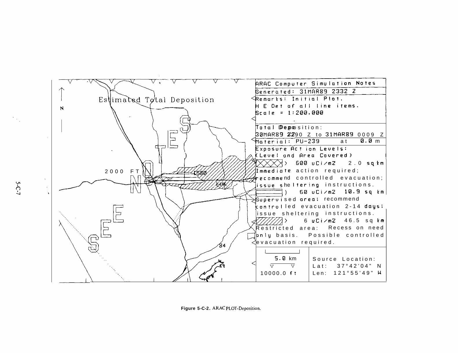
,.
I A\—
) 1— /~kLeuel und Rrea Couered) I
—Jm:i“otal D e p o s i t i o n :
L
0MQR89 2 2 9 0 Z t o 31MRR89 0 0 0 9 Z
\
ateriul: PU-239 a t 0.0 m
xposure Rct ion Leuels:
IxxxmI
2 0 0 0 F T tendhe)
[\
s e d area; r e c o m m e n dl e d e v a c u a t i o n 2 - 1 4 days;
612E! uCi/mZ 2 . 0 sq kma c t i o n r e q u i r e d ;c o n t r o l l e d e v a c u a t i o n ;
Itering i n s t r u c t i o n s .6B uCi/m2 1(3.9 sq km
.,,., B i s s u e s h e l t e r i n g i n s t r u c t i o n s .
E
Ezzzl’ 6 uCi/m2 4 6 . 5 s q kmR e s t r i c t e d a r e a : R e c e s s o n n e e d
\ only b a s i s . P o s s i b l e c o n t r o l l e de v a c u a t i o n r e q u i r e d .
L I. . . . . . . 5.9 km S o u r c e L o c a t i o n :. . . . ,, v v L a t : 3 7 ° 4 2 ’ 0 4 ” N
~. . . $. 1 0 0 0 0 . 0 ft L e n : 1 2 1 ° 5 5 ’ 4 9 ” H,.
—-~ ,. . . . . I
Figure 5-C-2. ARAC PLCJl_-Deposition.

1. Greater than 600 pCi/m2 - Immediateaction requ~ed. Urgent remedial action may be neededfrom within a few hours up to two days. Full anti-contamination clothing and respiratory protectionrequired by all emergency staff in this area. Residentsshould remain indoors with doors and windows closed.Room air conditioners should be turned off. Controlledevacuation of children and adults should be consideredurgent. All work on, or the use of, agricultural productsand/ or meat and poultry must be controlled and furtheraction regarding them assessed.
~ Greater than 60 pC1/ mt - Supervised area.Controlled evacuation should be considered and mayhave to occur between about two days and two weeksor more. All activities should be considered carefullyand supervised. Full anti-contamination clothing andrespirators required for all personnel engaged in heavywork or dusty, windy operations. Residents shouldremain indoors with windows closed unless evacuationis in progress or there is no significant airborne hazardand none forecast to occur via resuspension.
~ Greater than 6 pCi/ mz - Restricted area.Entry restricted to those who live, work, and/or havea need to be there. Decontamination personnel andpublic health and safety staff should wear limited anti-contamination protective clothing. Controlled evacua-tion of residents, especially children, is possible duringdecontamination if there is a possibility of airbornecontamination via resuspension.
c. Aerial Measurement System (AMS).
(1) General. The EG&G AMS has three capabilitiesavaiIable to support a weapon accident: aerial radio-logical mapping, aerial search for weapons and/ orweapon components, and aerial photography.
(2) Aerial Radiological Mapping. Aerial radiolog-ical surveys provide rapid assessment and thoroughcoverage of large areas and yield average groundconcentrations of the contaminant. The system can alsobe used to quickly prepare crude, but appropriatelyscaled, incident site maps. Instrumentation includeslarge-volume, sodium-iodide gamma-ray detectors, dataformatting and recording” equipment, positioningequipment, meteorological instruments, direct readouthardware, and data ‘analysis equipment. A variety ofDoE owned aerial platforms (fixed-wing and helicopter)are dedicated to supporting this mission. Also,equipment capable of being mounted on a variety ofDoD helicopters is available to perform survey missionsas needed.
(a) In, a nuclear weapon accident, a preliminaryradiological survey would establish whether radioactivematerials had been dispersed from the weapon.Dispersion patterns and relative radiation intensities,immediately available from the initial survey, may beused to guide radiation survey teams to the areas ofheaviest contamination. AMS personnel will assistinterpreting and correlating their information with otherradiological survey data. Additional data processing willestablish the identity and concentration of the isotopesinvolved. Subsequent surveys could provide data on theprogress of clean-up operations.
(b) The first radiological photography surveyconducted after a weapon accident is likely to followthis protocol and time frame:
1. The helicopter would arrive six to tenhours follo=ng notification.
~ The helicopter would then be refueled andthe crew would obtain instructions within two hours.
~ A survey would then be conducted in aserpentine pattern of survey lines 0.5 to five miles apartto determine:
& Radiological deposition outline.~ Direction of the plume centerline.q Approximate radiation levels along the
plume centerline.& Dominant isotopes.
+ Information from 3 would be transmittedby radio to base operations during the survey.
~ The analysis laboratory would arrive 4hours (plus driving time) after notification.
~ Full analysis of flight results would beavailable 6 to 12 hours after the flight is completed orafter the analysis laboratory arrives.
(c) After the first, broad survey is completed, aseries of smaller area surveys would be initiated. Theflight altitude would likely be 100 feet with 200 footline spacings. The purpose of these surveys would beto map the contaminated area in detail. The length oftime required to complete this series of surveys maybe from one to five days, depending upon the area tobe surveyed and the weather.
(d) The results of an aerial survey of Area 13of the Nevada Test Site is shown in Figure 5-C-3. Thiswas the site of a “one-point” detonation in the 1950sto simulate a weapon accident. The aerial survey data..were”analyzed for the 60 keV photopeak of Am241.
Detailed radiological contours, such as those shown in
5-C-8

Figure 5-C-3 would be available five to eight hours afterthe completion of the previous survey flight.
(e) The sensitivity of the system depends uponthe flight altitude, area of contamination and theinterference of other isotopes (both natural and man-made). Experience has shown that the lower level ofdetectability y of Am241 can be expected to be 0.03 to1.0 flCi/mz, and 0.03 to 0.3 #Ci/ mz for both CS137 and1131. The americium concentrations indicated representson the order of 1 to 10 flCi/ mz of plutonium.
(f) Comparison with ground-based survey andsample results should be done with caution. The areasampled in a single aerial measurement is on the orderof 1,000 times the area sampled by a FIDLER-typeinstrument at one (1) foot above the ground and1,000,000 times larger than the area sampled by an alphaprobe or a soil sample. The aerial survey results average-scale averages and take into account the overall effectof roads, ditches, water bodies, vegetation cover andterrain effects.
(3) Aerial Search. In certain scenarios, the aerialsearch capabilities available from AMS capabilities may
need to be employed. These consist of gamma andneutron detector modules designed for the DoE ownedBO-105 helicopters or portable modules that can be usedin helicopters, such as the UH-60 and U H- 1. Thiscapability may be useful only for certain sources ofknown detectability and normally requires low altitudes(100 feet or less) and slow speeds (approximately 60knots). Aerial search personnel will be able to determinethe appropriate flight parameters when notified of theparticular scenario.
(4) Aerial Photography. Two major photographicsystems are used to acquire detailed serial photos overa site. One system consists of a large format aerialmapping camera operated in fixed-wing aircraft, whichproduces detailed aerial photographs= The second systemoperates out of helicopters, utilizing the Hasselblad70mm cameras to produce color photographs. Film fromthe Hasselblad system can be produced and printedunder field conditions. Large prints up to 20” x 24”produced to map scales can be printed on-site generallywithin hours of the completion of the flight.
.
5-c-9

\
\ ..!
. ..””. . . .
\. . . . .
. . ..””. . . . .”
. ...’””. . . . .,.. ”
a
,. ...””’
~
.\ . . . . . . . . . . . . . . . . . . . . . . ..:/. ..-
,.. b9
● ““”’. 493
“WP? ““””:2/.
----
w(!)
v .-
“...LQ-,. .
5-C-1O

DoD 51OO.52-M
APPENDIX 5-D
AREA AND RESOURCES SURVEYS
5-D-1 SURVEYS
a. General. Extensive radiation predictions andsurveys will be required to identify and characterize thearea for decontamination and to develop and evaluaterestoration plans. During the initial hours of theresponse, available radiation survey instruments andmonitoring personnel for survey operations will belimited. Determining whether contamination wasreleased by the accident must be done immediately. Ifa release occurred, priority must be given to those actionsrequired to identify and minimize the hazards to people.These actions include identification of the affected area(perimeter survey) to permit identification of potentiallycontaminated people. Each successive survey operationwill be based in part on the information gained fromearlier operations. Initial radiation surveys may be basedon ARAC information, if available, or only on the knowl-edge that contamination will be dispersed downwind.Later surveys will be based on the initial survey dataand AMS plots. Days will be required to completecomprehensive contamination characterization.
b. General Survey Procedures. Selection of instru-mentation, identification of the edge of contamination,determination of the location of measurements made,and data recorqing procedures are similar for mostsurvey operations.
(1) Selection of Instrumentation.
(a) Alpha Instruments. Alpha instruments candetect lower levels of contamination than low energygamma instruments. Under field conditions, however,alpha radiation has an extremely short detection rangeand its detection may be blocked by nothing more thansurface moisture. Alpha surveys are possible only underdry conditions, for example, after any morning dew hasevaporated. The fragility of the Mylar probe face onmost alpha instruments combined with the shortdetection range of alpha radiation results in a high rateof instrument failure when field use requires measure-ment of contamination on rough ground or otherirregular surfaces. Alpha instruments should thereforebe used primarily for personnel and equipment
monitoring at the hot line. Field use should be limitedto only smooth surfaces like pavement and buildings.
(b) Low Energy Gamma Instruments. Instru-ments capable of detecting the low energy gamma- andx-ray radiations from plutonium, and its americiumdaughter, may be used to detect contamination. Low “energy gamma/ x-ray instruments are not subject todamage by surfaces being monitored and field surveyscan be rapidly conducted. Low energy gamma instru-ments are, therefore, the recommended instruments forfield surveys of plutonium contamination, whereas theSPA 3 probe is more useful for measuring the mediumenergy gamma radiation from uranium. For the bestdetection efficiency, low energy x-ray surveys should beconducted prior to any rainfall, and during the first fivedays after the accident before part of the measurablelow energy radiation present is screened by the plutoniummigrating into the soil. The best instrumentation forlow energy gamma/x-ray surveys uses FIDLER probes,which will not normally be available until the specializedteams arrive. The type and amount of low energy gammaand x-ray radiation present depends on the age of theplutonium. Many weapons will contain plutonium over10 years old, resulting in higher signal strengths for thesame level of contamination as that produced by a “new”weapon; therefore, the age of the plutonium andprojected signal strength should be determined as soonas possible. The age of the plutonium in a weapon canbe obtained from the DoE ARG.
(2) Perimeter Contamination Levels. When alphainstruments are used to establish the perimeter, readingsof 500 CPM are recommended for instruments with 60cm probe area and 105 CPM for instruments with 17cm probes be used to mark the perimeter. When lowenergy gamma/ x-ray instruments are used to establishthe perimeter, a reading of twice background isrecommended to mark the perimeter. FIDLERs arerecommended to perform perimeter surveys, with alphainstruments the second choice. If FIDLERs areunavailable, and if weather or field conditions precludethe use of alpha instruments, the AN/ PDR-56F, withthe x-ray probe attached, may be used. If fission products‘were caused by the accident, priority should be givento establishing a 10 mR/ hr perimeter.
5-D- I

(3) Fixing Survey Points.
(a) For radiation monitoring data to be useful,the point where it is collected must be identifiable ona map or aerial photo of the area, Engineering surveyequipment may be unavailable to determine precisepositions in the early phases of response, or theimmediate need for radiological data may outweigh thetime required to determine precise positions.
~. Data points should be marked in somemanner so that the point can be later relocated for otheractions, or the position determined precisely for latercorrelation of the data with other information.
~. A numbered or uniquely identified stakemay be used to mark the location on soil, and a similarunique identification painted or otherwise marked onpavement or other hard surfaces for later reference.When engineering survey equipment is not being used,the monitoring log, or data collection record, shouldshow the identification marking used at each point, andan estimated position to use immediately following datacollection.
~. Estimated positions may be street addressesin urban areas, the estimated distance down a streetor road from an identifiable intersection, compassbearings taken on two or more identified referencepoints, or any other reference which can be located onthe maps being used. If a vehicle is used during theinitial perimeter survey, the odometer mileage from anintersection or other known point may be adequate foridentifying positions in sparse[y populated areas.
(4) Recording Survey Data.(a) If an engi~eering survey is being performed
concurrently with the radiological survey, recordingprocedures must ensure that positional data beingrecorded at the transit position and radiological databeing recorded by the monitors can be correlated.Monitoring and survey teams’ records should includethe following information:
~. Team member names.~. Type instrument and serial number.~. Date and start/stop time of survey.~. Data location mark (stake number or other
marking) when used.~. Estimated or surveyed position,Q. Instrument reading indicating if the reading
is “Gross,” meaning background radiation reading hasnot been subtracted, or “Net” meaning the backgroundradiation reading has not subtracted from the instrumentreading.
(5) Perimeter Surveys.
(a) Initial Fkrimeter Survey. Rapid identificationof the perimeter of the contaminated area is requiredto prevent undue alarm, to aid in identifying affectedpeople, and to establish controls to prevent the spreadof contamination. The On-Scene Commander and civilauthorities will need at least a rough plot of the perimeteras soon as possible upon which to base their actions.The urgency of perimeter definition is directly relatedto the population in the area. Streets and roads willnormally provide rapid access to populated areas,although the location of rivers or other terrain featureswhich may hinder access to portions of the potentiallycontaminated area must be considered when directingthe perimeter survey. The contaminated area may bea mile or more wide and several miles long, thereforeuse of widely separated monitoring points and a vehicleto move between monitoring points should be consideredwhen directing the initiaI perimeter survey. ARACprojections, if available, will assist in determining thearea and distance the perimeter survey teams may berequired to cover, and perimeter survey procedures maybe adjusted accordingly. If perimeter survey teams areequipped with a radio, a position report at the perimeterlocations on each traverse will provide an immediatelocation of the perimeter to the command center andpermit team progress to be tracked. While not classified,transmissiorr of radiation readings should be discouragedon unsecure nets.
(b) Full Perimeter Survey. FIDLERs should beused when performing a full survey of the perimeter.This may not be possible until after the specialized teamsarrive and may take weeks to complete. The proceduremost likely to be used will consist of monitoring in andout along the edge of the area with readings being takenabout every 50 feet. If weather or terrain require theuse of the AN/ PDR-56 x-ray probe on the initialperimeter survey, the full perimeter survey can resultin an expansion of the perimeter. If an alpha instrumentwas used for the initial perimeter survey, the perimeterestablished by the fuIl perimeter survey should be aboutthe same size or slightly smaller.
(6) Area Surveys.
(a) Radiological surveys of the contaminatedarea are required to identify areas requiring fixation,to support decontamination and restoration planning,and jo determine decontamination effectiveness. Thefirst survey covering the entire area wiil be providedmost times by the Aerial Measurement System~AMS).
5-D-2

The initial AMS data will be available four-five hoursafter completion of survey flights. The AMS plot requiresinterpretation by trained analysts. Ground survey datais required to validate and support analysis of the plot.Some of the supporting ground data may be providedby the initial perimeter survey. Ground surveys tosupport decontamination planning will be performedwith FIDLERs. Usually some form of grid survey willbe used with the grid size determined by the desiredaccuracy of estimated activity between grid points andmeasurement errors associated with the instruments.From several days to over a week may be required tocomplete a ground survey of the entire area. Groundsurveys validating decontamination effectiveness mayrequire several months to complete due to the low levelsof contamination remaining, and the desired precision.
(7) Building Surveys.
(a) Radiological surveys of buildings within thecontaminated area will be required to determine theappropriate decontamination actions. Alpha instru-ments may be used on most building surfaces, however,use of FIDLERs may be necessary on surfaces whichmay damage alpha instruments, or on materials suchas carpets where contamination maybe below the surfaceand screened from alpha instruments. The amount ofremovable contamination present must be determinedby wiping surfaces with a piece of material, or swipe,which is then monitored for contamination it absorbed.Laboratory counting equipment should be used todetermine the amount of removable contaminationabsorbed by the swipe. Initial building surveys shouldbe performed only on the exterior unless the buildingis in use.
(b) Civil authorities should establish proceduresfor either building owners and/ or tenants, or anappropriate civil authority, such as a policeman, toaccompany monitors when surveying building interiors.If interiors are surveyed before the surrounding areahas been decontaminated, methods which minimizetracking of contamination into ,buildings should be used(for example, cover shoes with plastic bag immediatelybefore entering buildings and ensure gioves areuncontaminated). Interior contamination levels will varybecause of the time of year, the t ype of heating or coolingsystem used, and whether or not people were in thebuilding at the time of, or following the accident. Interiorcontamination levels will be only a fraction of theexterior levels at the same location. The primary sourceof interior contamination are expected to be airbornecontaminants entering the building through heating orcooling systems, and doors, windows, or other openingsduring the initial cloud passage; or contaminationtracked or carried into the building by people or animals.The sealing of doors, windows, chimneys; and ventilatorson evacuated buildings in highly decontaminated areasmay minimize further contamination of the interiorduring contamination of the surrounding area. Whenmonitoring the interior of a building, initial monitoringshould be on the floor in the main traffic pattern(doorways, halls, and stairs), and on top of horizontalsurfaces near heating or cooling duct outlets, windowsand other openings into the building. If no contami-nation is found at these locations it is very likely nocontamination entered the building. If contaminationis found, additional monitoring should be performed.Monitoring results from furnace and air conditioningfilters should be included in building survey records.
.
5-D-3

DoD 51 OO.52-M
APPENDIX 5-E
RADIOLOGICAL MONITORING, MEASUREMENT,
AND CONTROL FORMS
Accurate records should be maintained of exposure times and levels of exposureexiting the accident area. Additionally, a complete radiological history should be
for all personnel entering andmade for each individual who
is actually contaminated. This appendix contains examples of forms that may be used to document and recordthis information.
Form 1 -
Form 2 -
Form 3 -
Form 4 -
Form 5 -
Form 6 -
Form 7 -
Form 8 -
Personal Data FormThis form contains data which should be obtained from all personnel who enter the radiologicalcontrol area.
Radiological Control Area LogThis form is for use at the contamination control station.
Bioassay Screening LogThis form is for maintaining a record of all necessary bioassay screening performed andused for both response force personnel and civilians who may have been contaminatedof the accident.
Radiation Health HistoryThis form is to assist in the screening of civilians who may have been contaminatedof the accident.
Field Monitoring Data LogThis form is to assist in documenting field monitoring measurements by survey teams.
TLD MeasurementsThis form is to be used to document TLD readings.
Weapons Accident Environmental RadiationThis form is to be used to log samples taken from the surrounding environment.
FIDLER Data FormThis form is used when logging readings from the FIDLER.
as
as
may bea result
a result
5-E-1

5-E-2

FORM 1
PERSONAL DATA FORM
(P/em print or place “X” in boxes as appropriate)
Sa Ravarm for Additional Inarructlons
‘l) SOCSEC NO ‘2)NAME ‘3) BIRTH OATE
IIasr) (firrtl [m.i.l (dw)(month)(vr)
‘4) MALE0 o r FEMALE ❑
‘5 A) MILITARY ❑ or ‘5 B) CIVILIAN m
(6) “SA m ‘7 } GFIAOE (9A)
[ B]
(9B) “SA
USAF
U S A F D (8) C#EC, ALITy CfJOE 000 ❑ USN (10) GRAOE (111.jERIEs
or uSMC
USN m NEC/DESIGNATOR
( -jUSMC D ‘JOE cl---”~”n-n
OTHER D OTHER D–––––––
ISpwlfv)
(121HAv E YOU E1/ERWIJRN A FILM BAOGE OR OTHER 00 SIMETRIC 0EVICE7
(13~HAVE yf)u EVER BEEN CLASSIFIED AS A’”RAOIATION WORKER”?
‘14) HAVE YOU HAO TRAINING IN RESPIRATORY PROTECT IO NEOUIPMENT (MASK)?
(15)”Av Ey0uw0RKE0 1~ *NT,. contamination CLOT” ING ANO Respirators?
116) HAVE YOU RECE,VEO AS, GN, F,CANT OIJsE OF RADIATION WITHIN THE LAST YEAR?
(17)” AvEy0u BEEN BRE, FEO ONp RIJCEL)u REs FOR wORKING IN A CONTAMINATE AREA?
~181youR ORGAN IZATION/BUSINESs AOORESS:
(Yes)
c1c1c1nnn
I3RAOE SERIES
PROFESSION AGENCY
(No)
c 1
c 1
n
n
un
lUmt/Emplow Nnmo or Svmbol) lStraat, P.O. Box. Mail Stop, etc.l
.>
(CIrV or Milirw Base) [State or County) (ZIP Code)
(19) UNIT RESpONS, ELE FOR RECOROING yOu R RAIJIAT]ON OI)SIMETRY RESULTS[Place “X” if unknown}
(201y0u R ORGANIZATION/BUSIN ESs TELEPHONE(Area Code tmd Number)
(signature) IOa!e)
FOR RAO HEALTH CENTER USE
FILM BAOGENO
EXTERNAL OOSE
INTERNAL 00SE
PERSONAL OATA FORMACCOUNTING NUMBER
T H I S FOWM SUBJECT TO THE PRIVACY ACT.
,-
Figure 5-E-1. Personal Data Form.
5-E-3
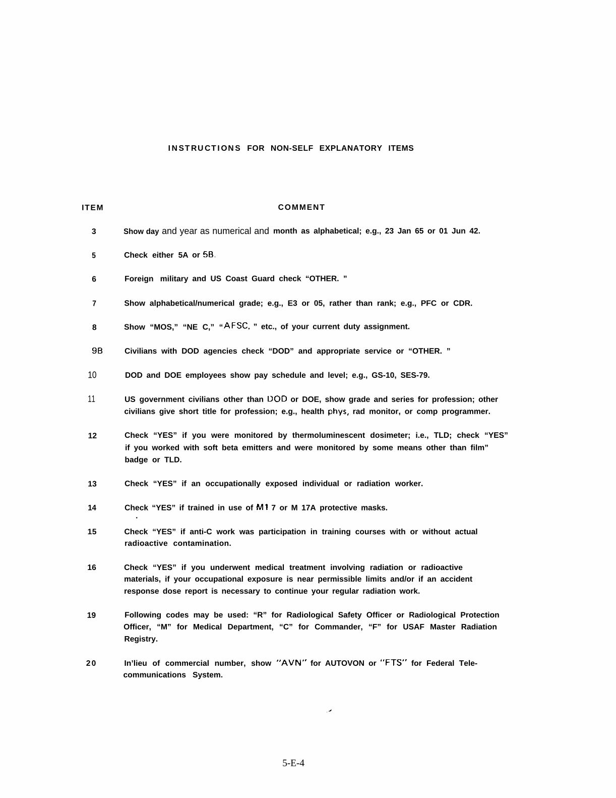
INSTRUCTIONS FOR NON-SELF EXPLANATORY ITEMS
ITEM
3
5
6
7
8
9B
10
11
12
13
14
15
16
19
20
Show day and year as numerical and
COMMENT
month as alphabetical; e.g., 23 Jan 65 or 01 Jun 42.
Check either 5A
Foreign military
or 50,
and US Coast Guard check “OTHER. ”
Show alphabetical/numerical grade; e.g., E3 or 05, rather than rank; e.g., PFC or CDR.
Show “MOS,” “NE C,” “AFSC, ” etc., of your current duty assignment.
Civilians with DOD agencies check “DOD” and appropriate service or “OTHER. ”
DOD and DOE employees show pay schedule and level; e.g., GS-10, SES-79.
US government civilians other than DOD or DOE, show grade and series for profession; other
civilians give short title for profession; e.g., health phys, rad monitor, or comp programmer.
Check “YES” if you were monitored by thermoluminescent dosimeter; i.e., TLD; check “YES”
if you worked with soft beta emitters and were monitored by some means other than film”
badge or TLD.
Check “YES” if an occupationally exposed individual or radiation worker.
Check “YES” if trained in use of Ml 7 or M 17A protective masks..
Check “YES” if anti-C work was participation in training courses with or without actualradioactive contamination.
Check “YES” if you underwent medical treatment involving radiation or radioactivematerials, if your occupational exposure is near permissible limits and/or if an accident
response dose report is necessary to continue your regular radiation work.
Following codes may be used: “R” for Radiological Safety Officer or Radiological Protection
Officer, “M” for Medical Department, “C” for Commander, “F” for USAF Master Radiation
Registry.
In’lieu of commercial number, show “AVN” for AUTOVON or “FTS” for Federal Tele-communications System.
5-E-4
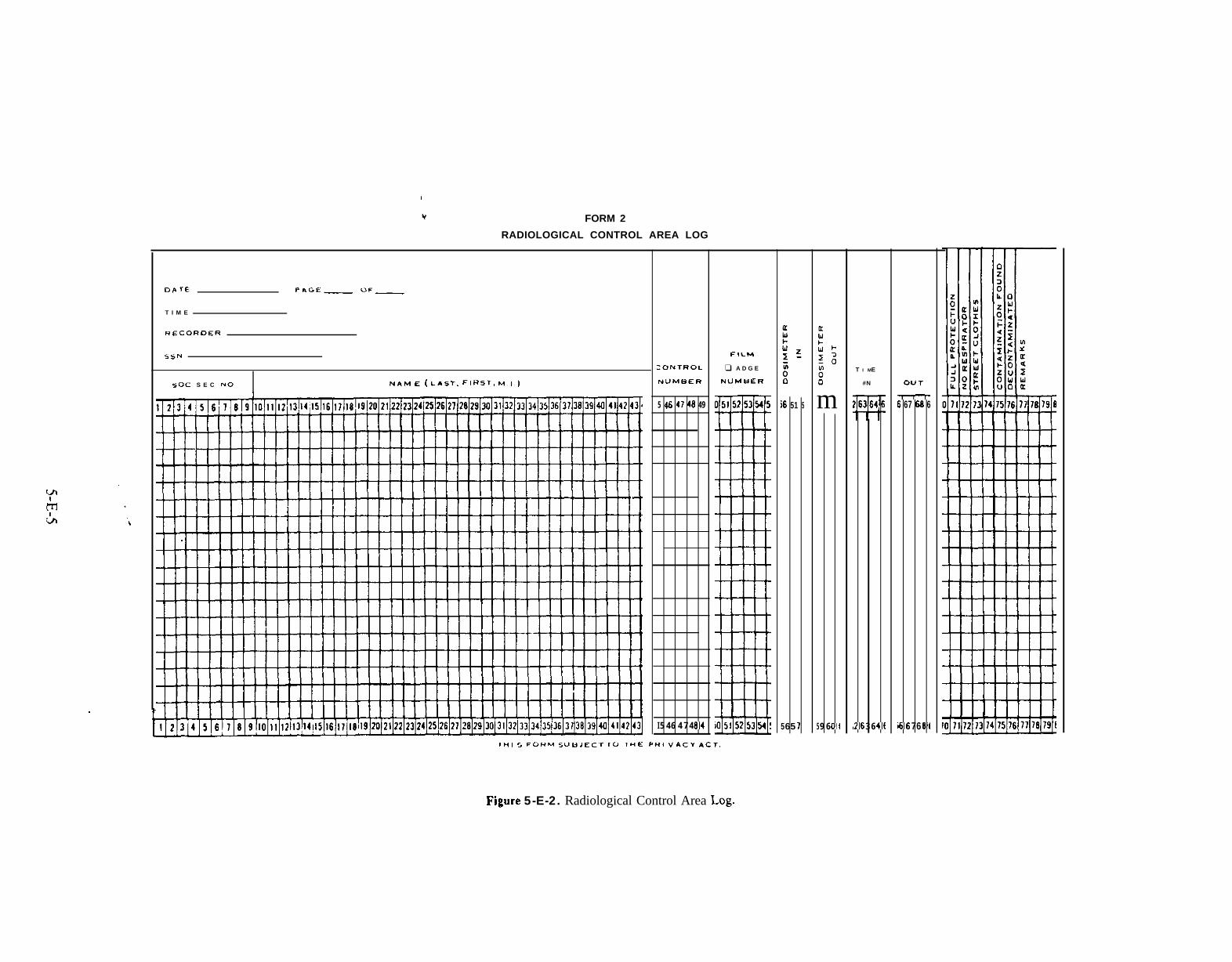
r
v FORM 2
RADIOLOGICAL CONTROL AREA LOG
OP. TE FAG=— ~F—
T I M E
.E CORDER
5sN
50C S E C NO NAM E( LAST, FIHST, MI)
;oNTROL
NUMBER
5 46 47 48 49
I 5 46 4 7 484
F6LM
❑ A D G E
NUMe ER
s 51 5
565 1
m
59 60(
T I ME
#N
i ?6 3 6 4(
Ou T
—s 67 60 6
66 768[
lM, S FOI+M 5UL3JECT 10 THE PR, VACV &CT.
Figure 5-E-2. Radiological Control Area Log.
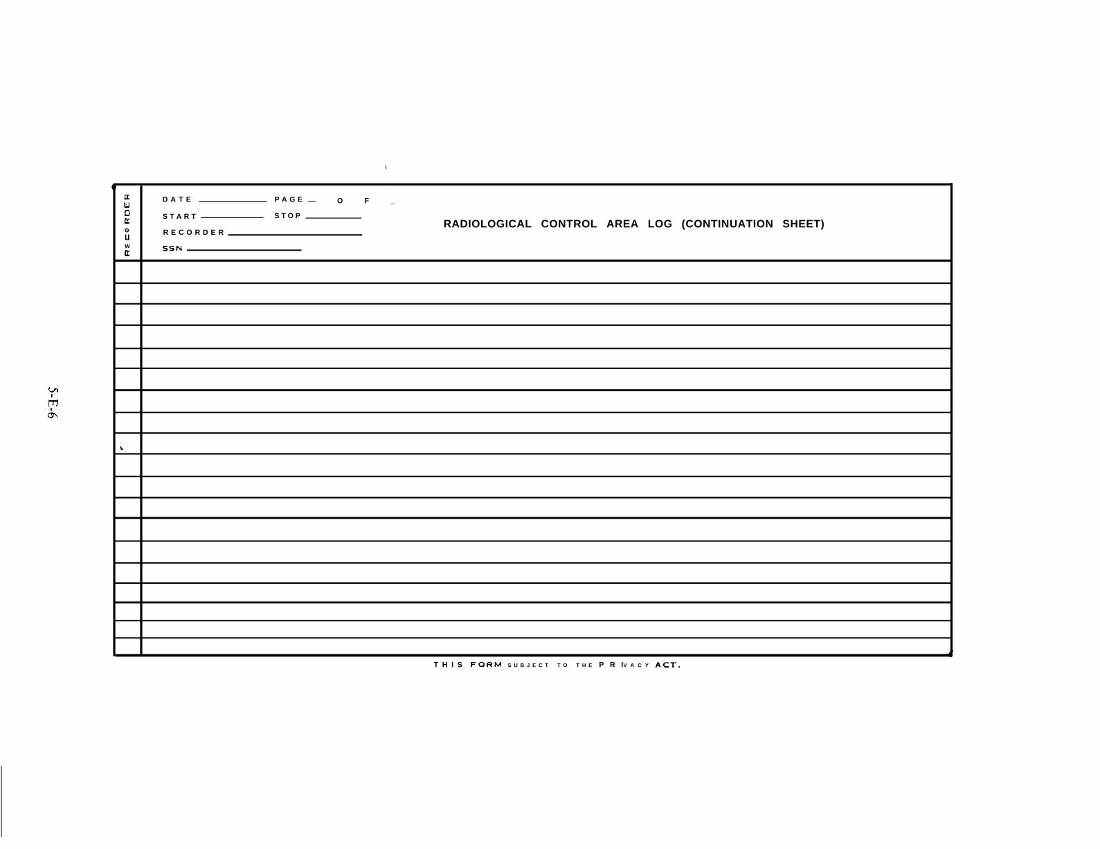
WI
h&
I
●,
lxu D A T E P A G E — O F _
oE
S T A R T S T O P
oRADIOLOGICAL CONTROL AREA LOG (CONTINUATION SHEET)
u R E C O R D E R
wu’
SSN
\
4T H I S FORM S U B J E C T T O T H E P R IV A C Y ACT.

yl
mL
a.
b.
c.
d.
e.
f.
9.
INSTRUCTIONS FOR THE USE OF THE RADIOLOGICAL CONTROL AREA LOG
Column 71 should be marked with an X if the person was wearing full anti-contamination clothing and a respirator.
Column 72 should be marked with an x if the person was wearing anti-contamination clothing without a respirator, or street clothingwithout a respirator.
Column 73 should be marked with an X if the person was wearing street clothing.
Column 75 should be marked with a Y if contamination was found on body or personal clothing when exiting the control area
contamination was detected state “none. ”
Column 76 should be marked with a ‘f if all detected contamination was removed from the person, N if not and remarks are
mandatory. If no contamination was detected state “none. ”
If no
Any unusual incidents or additional data deemed important for radiological safety should be described in the remarks section and
sequentially numbered. The number should be inidcated in Columns 77. 80. Remarks may also be used to indicate when recorders
change in mid sheet. If Personal clothing was confiscated during decontamination, articles taken should be noted in remarks.
Each day should be started with a new form and the total ”number of pages entered on each sheet of the previous days forms.

5-E-8

y“’m
‘b L
vFORM 3
BIOASSAY SCREENING LOG,
D Am PhGE OF_
T I M E●a
*ECORDERc :w
I I
In:
SSN: ; Xz
~ o ~ xl.v ~ o t?; o ; <u
SOC S E C N O L A S T N A M E- ● w !4z e e 1 “ ,
D E TECTEO
I
cOu NT
:ONTROL
NUMBER
I .1 I
THIS FOFt M S U B J E C T T O T H E P!?, vACY ACT
Figure 5-E:3. Bioassy Screen Log.

IAY I DAT~ pAGE —OF~
E S T A R T STOP. BIOASSAY SCREENING LOG (C O N T I N U A T ION S H E E T): R E C O R D E Rw
K S S N
,....,L
ti 1Ii 1
I
4
1 IT H I S F O R M S U B J E C T T O T H E P R I V A C Y A C T ,
J

INSTRUCTIONS FOR THE USE OF THE BIOASSAY SCREENING LOG
y)
mA
a,
t).
c.
d,
e.
f,
9.
h,
i,
j.
k,
1.
m.
Columns
Column ;
O-23. If more than 14 characters in last name truncate as necessary.w
1 indicate with M or C,
Column 25 should be marked with Y if person is normally classified as a radiation worker by the Nuclear Regulatory Commission,leave blank for all others.
Column 26 should be marked Y if person is not associated with a DC)D, Federal or state accident response organization, leave blank
for all others.
Column 27. Insure all persons marked Y in Column 26 have completed a Radiation I+ealth History form and check, leave blank for
all others.
Columns 28-39 should be marked Y where appropriate if contamination was found and column number and associated readingrecorded in the remarks section. All personal articles and clothing retained for decontamination or disposal should be recorded in the
remarks section. If no contamination was detected leave blank,
COIUmn 40 should be marked Y if all detected contamination was removed from the person, N if not and remarks are mandatory, Ifno contamination was detected leave blank,
Columns 41, 46, and 47 mark with Y if bioassay samples collected, N if not.
Columns 42-45, 48-51, 52-56, and 57-61 enter units used in column headers and measurements in appropriate columns.
Columns 62-65 enter time bioassay sample was collected.
Column 71 mark Y if additional bioassay samples or other data is required and specify in remarks section.
Any unusual incidents or other data deemed important should be described in the remarks section and sequentially numbered, The
number should be indicated in Columns 77-80, Remarks may also be used to indicate when recorders change in mid sheet.
Each day should be started with a new form and the total number of pages entered on each sheet of the previous days forms.

y
qll .

FORM 4
RADIATION HEALTH HISTORY
(Please print or place “X” in boxes as appropriate)
(1) SOCSEC N O (2) NAME
(last) (first)
(3A) BIRTH DA-
(4)
(5)
(6)
(7)
(8)
TEMPORARY ADDRESS
(m.i.)
E (3B) M A En o r FEMALEU
sfaylrnolyr
TELEPHONE “
PERMANENT AIICIRESS
TELEPHONE
NAME& AD ORESSOF EMPLOYER
HAVE YOIJ EVER BEEN TREATED WITH X-RAYS OR RADIOACTIVE ISOTOPES?‘Escl ‘on
(7A) REASON FOR TREATMENT
(7B) DATE OF TREATMENT
mo/yr
(7C) PLACE OF TREATMENT
HAVE YOU EVER HAD ANY CANCER OR OTHER MALIGNANCY? YKI Non
(8A) INDICATE TYPE-.
LEUKEMIAD BREAST ❑ THYROID ❑ LUNG ❑ STOMACH ❑ BONE ❑I N T E S T I N E S O OTHER ❑
Specify type
(8B) DATE OF OIAGNOSIS
molyr
T H I S F O R M S U B J E C T TO T H E P R I V A C Y A C T .
,-
Figure 5-E-4. Radiation Health History.
S-E-13

(9)
(lo)
(11)
(12)
(13)
(14)
(15)
(161
(17)
(18)
HAVE ANY BLOOD RELATE D MEMBERS OF YOUR FAMILY (G RANDPARENTS, PARENTS, BROTHERS OR SISTERS)
EVER HAD CANCER OR LEUKEMIA? YES ❑ NO ❑ TYPE
ARE YOU NOW TAKING MEDICATION? YES ❑ NO O
(1OA) WHAT MEDICATION
DO YOU HAVE ANY ALLERGIES? YES D NO ❑
(11A) WHAT ALLERGIES
NAME & ADDRESS OF FAMILY PHYSICIAN
OATE & TIME OF POSSIBLE OR ACTUAL EXPOSURE -,. -.-,.- , -.,--.,-. . ., .,.-,-.! . ..n . . ..n
DURATION OF EXPOSURE HOURS
ACTIVITIES DURING PERIOD OF EXPOSURE (Meals, type work, bathing, sleeping, etc. )
IU HAUIAI lUN&UNIAMINAll UN AM u or r~u
day/mo/yr t i m e
MINUTES
LOCATION OURING PERIOO OF EXPOSURE — —
DO YOU OWN A PET? YES D ho ❑ TYPE
LOCATION
WHO WAS WITH YOU WHEN YOU MAY HAVE BEEN CONTAMINATEO?
NAME AODRESS TELEPHONE
5-E-14
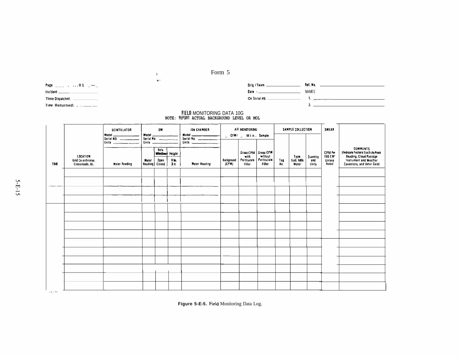
Form 5
u!
hLL/l
Page _ _ _ . . . . 0 1 _ — _
Incldenl _
Time Olspalched:
llme Returned: . .–——
TIME
.—. _
,,, ,.7!
toclllonGrid Coordinalas.Crossroads. tic.
Orlg Ilnam Ref. No,
0?18 - NAMES
Or $:rial !i8 !. ——
2.
FIELD MONITORING DATA 10GNOTE: REPORT ACTUAL BACKGROUND LEVEL OR MOL
mWindow Maiohl
Momr Open 4 In.Meler Rcadlng ReadlnQ Closed 3 II Mtler TImdlng
==H=H=
Alfl MONITORING SAMPLE COILICTION
_ CIMI _ M i n . S#mplo
Gross CPM Crou C?Mwllh wllhoul Type. Ou8ntlty
Background Pl{llc”la16 Parllc”lala Ttg Soil. Milk andICPMI Filler Filler No. Wmr Unlta
I I I I t
I 1 1 f I
.
SMEM
CPM Pet100 CM1UnlessNoled
COMMINTSflfidlcate Flclors Such k: PeIk
Ileadlng, CIOUO PassageInslrumenl ml Wtalh!r
Condillons, and Olher OaIeI
IFigure 5-E-5. Field Monitoring Data Log.

.
5-E-16

Form 6
TLD MEASUREMENTSCOLLECTION ANO ANALYSIS
--J
I
INCIDENT ‘ -,PAGE ______ OF ______
——
LOCATION[BE SPECIFIC, GRIDCOORDINATES, ETC. I
–--’————l——~
TEAMIORGANIZATION
----1I—- —.. . .. —.—— __
—. ..—-1‘----t--‘--’_i—---—–––4–––
I-“------+
A.-_— ._. ..— —I.—— —— —-—
------+-
—____—l.—II
1 PLACEO FIETRIEVEO
TIME OATE TIME
— — —
.— .—— .—.—
——— ..— — —c
-. .—. .-— . _____ ._
— . —
—
I
-LASSUMEDFIEAEIING BACK.
GROUNO
I
d—. ——.-1-
1
LABORATORY
LAB MANAGER
ROUTETO _OEA
READOUTNET UNITS
REAIJINGOATE TIME
—
— —
—.—— _ _ _ . . . . . . . . . .
.—-—
“RANSITI)TORAGE COMMENTS
OOSE
I
Figure 5-E-6. TLDMeasurement Collection and Analysis Form.

5-E-18

WEAPONS ACCIDENT ENVIRONMENTAL RADIATIONALPHA PROBE DATA FORM
NOTE: REPORT ACTUAL BKG OR MDL
Incident
Agency /Org.
Detector Type
Instrument BKG _
Instrument MDL
Date Data Type: Alpha _ _ B e t a _. Gamma —
T e a m / M o n i t o r _
Model No.
Calibration
Serial No.
Date Conversion Factor
Sample COlleciiOn CommenlsLocations Type: Soil. [Indicates Factors Such As Peak
Grid Coordinates. Milk. Waler, Reading. Cloud Passage, InslrtimenlTime Crossroads. etc. Reading Units Tag No. Air Filter and Weather Conditions. and Olher Data]
-%
. ’
Figure 5-E-7. Weapons Accident Environ”mental Radiation Alpha Probe Data Form,
5-E-19

,
5-E- 20
.
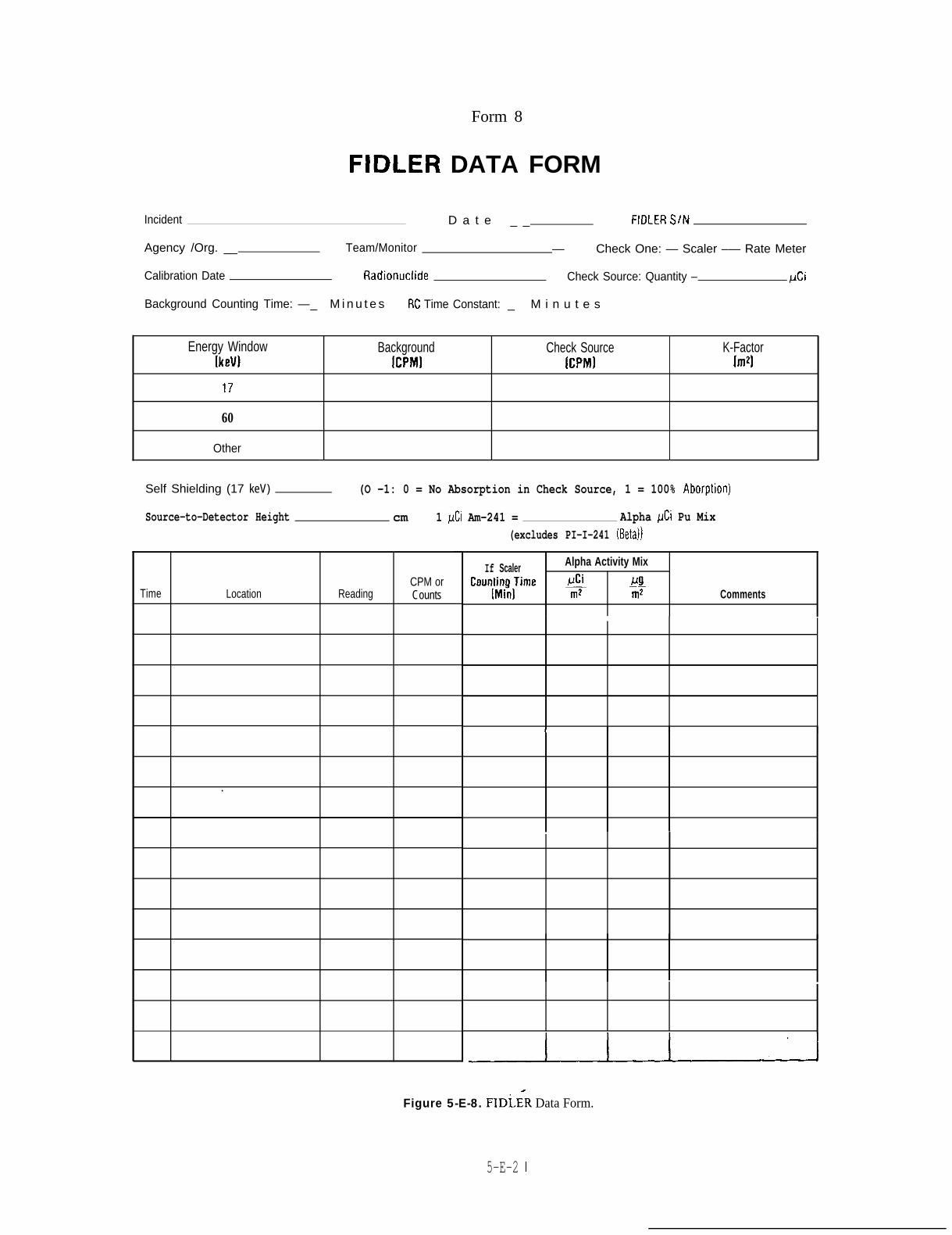
Form 8
FIDLER DATA FORM
Incident D a t e _ _ FIDLER SItd
Agency /Org. __ Team/Monitor — Check One: — Scaler –— Rate Meter
Calibration Date Radionuclide Check Source: Quantity – pCi
Background Counting Time: —_ M i n u t e s RC Time Constant: _ M i n u t e s
Energy Window Background[keV)
Check Source K-FactorICPM) [CPM] [rrrz]
17
60
Other
Self Shielding (17 keV) (O -1: 0 = No Absorption in Check Source, 1 = 100% Aborption)
Source-to-Detector Height cm 1 pCi Am-241 = Alpha pCi Pu Mix
CPM orTime Location Reading Counts
.
(excludes PI-I-241 (Beta))
If Scaler Alpha Activity Mix
Coun~{$Ume $ &~2 Comments
1
.
Figure 5-E-8. FIDLER Data Form.
5-E-2 1

.,
5-E-22