Embed Size (px)
Citation preview

CHAPTER 5
PIPE MATERIALS


Pipe Materials 5-1
Chapter Table of Contents 5.1 Introduction .................................................................................................................... 5-3 5.2 Policy and Practice ......................................................................................................... 5-3 5.3 Pipe Material Abbreviations ......................................................................................... 5-4 5.4 Definitions ....................................................................................................................... 5-4 5.5 Pipe Materials................................................................................................................. 5-4
5.5.1 Concrete Pipe ................................................................................................... 5-4 5.5.2 Metal Pipe ........................................................................................................ 5-6
5.5.2.1 CMP Wall Thicknesses ................................................................. 5-6 5.5.3 Plastic Pipe ....................................................................................................... 5-7
5.5.3.1 High Density Polyethylene Pipe (CPEP, SRPEP, and SWPEP) .... 5-7 5.5.3.2 Polyvinyl Chloride (PVC) .............................................................. 5-7 5.5.3.3 Polypropylene Pipe (CPP) .............................................................. 5-9
5.6 Pipe Connections ............................................................................................................ 5-9 5.7 Design Life .................................................................................................................... 5-13 5.8 Service Life ................................................................................................................... 5-18
5.8.1 Fire ................................................................................................................. 5-19 5.8.2 Corrosion ........................................................................................................ 5-19 5.8.3 Abrasion ......................................................................................................... 5-22
5.9 Fill Heights .................................................................................................................... 5-26 5.9.1 Fill Heights for SWPVCP .............................................................................. 5-27
5.10 Pipe Material Selection Procedure ............................................................................. 5-30 5.10.1 Example - Selecting Alternate Materials for a Culvert .................................. 5-32 5.10.2 Example - Selecting Alternate Materials for a Storm Drain .......................... 5-36
April 2014 ODOT Hydraulics Manual
5-2 Pipe Materials
Chapter Table of Contents, Contd.
--Figures-- Figure 5-1 Annular and Helical Corrugations .......................................................................... 5-11 Figure 5-2 Concrete Pipe Connections ..................................................................................... 5-13
--Tables--
Table 5-1 Pipe Material Abbreviations ....................................................................................... 5-5 Table 5-2 Wall Thickness ........................................................................................................... 5-7 Table 5-3 Pipe Material Design Lives and Alternate Materials for Culverts, Storm Drains, Subsurface Drains, Slotted Drains, Irrigation Systems, and Siphon.......................................... 5-15 Table 5-4 Pipe Material Service Lives...................................................................................... 5-21 Table 5-5 Abrasion Levels and Countermeasures ..................................................................... 5-24 Table 5-6 Bed Materials Moved by Various Flow Depths and Velocities ............................... 5-25 Table 5-7 Fill Height Table for SWPVCP ................................................................................. 5-28
--Plates--
5-1 Plan and Profile for Storm Drain Example Problem
ODOT Hydraulics Manual April 2014

Pipe Materials 5-3
5.1 Introduction
Many types of pipe materials are used in highway construction. The materials must be suitable for the site conditions so the facility will perform as intended. This chapter provides material selection guidance. 5.2 Policy and Practice
Agency policy for pipe material selection is to specify alternate materials where they can be used. Agency practice to implement this policy is in this chapter. This practice addresses most pipe applications. Additional material requirements or exceptions may occur for structures designed using ODOT Bridge Section policy and practice. Changes to alternate material practice and policy in the interim period between chapter updates will be addressed in ODOT Roadway Technical Bulletins. Guidelines and criteria for specific materials and applications are in the remainder of the chapter. Pipe material choices are based on all of the site conditions, and they must:
• satisfy project alternate pipe materials selection according to Title 23 Code of Federal Regulations (CFR) 635.411 (material or product selection)
• provide adequate hydraulic properties such as size and surface smoothness, • withstand static forces caused by the weight of the pipe, the fluid in the pipe, and the
weight of the fill over the pipe, • withstand static and dynamic forces caused by wheel and track loads from traffic and
construction equipment, pipe installation equipment and processes, pipe maintenance equipment and processes, and turbulent and unsteady flow within the pipe,
• withstand internal pressure to prevent the fluid from leaking out of the pipe into the surrounding bed materials,
• in the case of perforated or slotted pipe, to allow fluid from the surrounding bed material to enter the pipe,
• provide an adequate service life in relation to the design life of the facility, • withstand corrosion caused by the fluids conveyed by the pipe, • withstand corrosion caused by the surrounding soil if the pipe is in contact with the soil, • withstand abrasion inside the pipe from solids carried by the flow, • in certain applications, withstand combustion, • provide desired fish passage characteristics, be non-toxic to the surrounding environment,
and satisfy other environmental requirements, • satisfy local government preferences, if required, and • fulfill the need for experimental installations.
Each culvert, storm drain, or other installation shall be studied and suitable alternate materials allowed. The alternate materials must satisfy the requirements in the preceding list.
April 2014 ODOT Hydraulics Manual

5-4 Pipe Materials
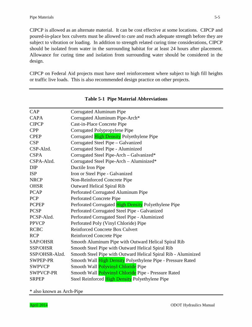
5.3 Pipe Material Abbreviations
There are many types of pipe materials, and the abbreviations for these names are listed in Table 5-1. 5.4 Definitions
Definitions and terms important to understanding pipe materials are listed in this section. Additional definitions are located in the manual glossary. ASTM – Acronym for American Society for Testing and Materials (ASTM). ASTM is a non-profit organization that provides specifications covering the manufacture of pipes. AWWA – Acronym for American Water Works Association. AWWA provides specifications covering the manufacture of pipes used in the water industry. Dimension Ratio (DR) - Sidewall thickness to outside diameter ratio as defined in AWWA specifications. Standard Dimension Ratio (SDR) - Sidewall thickness to outside diameter ratio as defined in ASTM specifications. 5.5 Pipe Materials
Numerous pipe materials are used in highway construction. More than one material can be used for most applications. The most commonly used pipe materials are discussed in this section. Additional requirements are in the Notes to Table 5-3. 5.5.1 Concrete Pipe
There are three types of concrete pipe allowed in the ODOT alternate materials policy; non-reinforced (NRCP), reinforced (RCP), or cast-in-place (CIPCP). Concrete pipes are used for culverts, storm drains, subsurface drains, and siphons. They are generally limited to non-pressure (gravity flow) applications. NRCP and RCP are specified using AASHTO M 86 or M 170 classifications, respectively. The strength of the pipe increases as the class designation increases. Class 1 NRCP and Class I and II RCP lack structural strength and they are rarely used.
ODOT Hydraulics Manual April 2014
Pipe Materials 5-5
CIPCP is allowed as an alternate material. It can be cost effective at some locations. CIPCP and poured-in-place box culverts must be allowed to cure and reach adequate strength before they are subject to vibration or loading. In addition to strength related curing time considerations, CIPCP should be isolated from water in the surrounding habitat for at least 24 hours after placement. Allowance for curing time and isolation from surrounding water should be considered in the design. CIPCP on Federal Aid projects must have steel reinforcement where subject to high fill heights or traffic live loads. This is also recommended design practice on other projects.
Table 5-1 Pipe Material Abbreviations
CAP Corrugated Aluminum Pipe CAPA Corrugated Aluminum Pipe-Arch* CIPCP Cast-in-Place Concrete Pipe CPP Corrugated Polypropylene Pipe CPEP Corrugated High Density Polyethylene Pipe CSP Corrugated Steel Pipe – Galvanized CSP-Alzd. Corrugated Steel Pipe - Aluminized CSPA Corrugated Steel Pipe-Arch – Galvanized* CSPA-Alzd. Corrugated Steel Pipe-Arch – Aluminized* DIP Ductile Iron Pipe ISP Iron or Steel Pipe - Galvanized NRCP Non-Reinforced Concrete Pipe OHSR Outward Helical Spiral Rib PCAP Perforated Corrugated Aluminum Pipe PCP Perforated Concrete Pipe PCPEP Perforated Corrugated High Density Polyethylene Pipe PCSP Perforated Corrugated Steel Pipe - Galvanized PCSP-Alzd. Perforated Corrugated Steel Pipe - Aluminized PPVCP Perforated Poly (Vinyl Chloride) Pipe RCBC Reinforced Concrete Box Culvert RCP Reinforced Concrete Pipe SAP/OHSR Smooth Aluminum Pipe with Outward Helical Spiral Rib SSP/OHSR Smooth Steel Pipe with Outward Helical Spiral Rib SSP/OHSR-Alzd. Smooth Steel Pipe with Outward Helical Spiral Rib - Aluminized SWPEP-PR Smooth Wall High Density Polyethylene Pipe - Pressure Rated SWPVCP Smooth Wall Polyvinyl Chloride Pipe SWPVCP-PR Smooth Wall Polyvinyl Chloride Pipe - Pressure Rated SRPEP Steel Reinforced High Density Polyethylene Pipe * also known as Arch-Pipe April 2014 ODOT Hydraulics Manual

5-6 Pipe Materials
5.5.2 Metal Pipe
Five types of corrugated metal pipe (CMP), are typically used in highway construction; iron or steel pipe (ISP), corrugated steel pipe (CSP), outward helically wound spiral rib pipe (OHSR), structural plate pipe, and ductile iron pipe (DIP). ISP is typically small diameter galvanized pipe with threaded connections. It is often used for water distribution systems, irrigation systems, and small drains. CMP is used for gravity flow (non-pressure) systems, such as culverts, storm drains, subsurface drains, slotted drains, and siphons. These pipes are available in several materials, such as aluminum, galvanized steel, or aluminized steel. OHSR pipe is used for gravity flow culverts and storm drains. Unlike CMP, it has a smooth interior. This can provide added flow capacity in some applications. It is available in the same materials as CMP. Structural plate pipe is composed of many corrugated metal plates that are bolted together. It is used for non-pressure applications such as culverts, equipment passes, and cattle passes. It is rarely used for other purposes. An advantage of structural plate is its ability to be transported in small sections or pieces to the jobsite and be bolted together in its final location. This can be very useful in areas with limited clearances for transport or construction. Structural plate pipes are available in the same materials as CMP. DIP can be used for gravity or pressure flow applications. It has great strength and it is typically used where this strength is required. Pipes with minimal fill cover are the most common use in highway construction. DIP is rarely used for an entire drainage system because of its expense. It is used for the pipes where its strength properties are required, only. Less costly pipes are used for the remainder. 5.5.2.1 CMP Wall Thicknesses Corrugated metal pipe (CMP) wall thicknesses are specified to the nearest 0.001 inches. Standard wall thicknesses are listed in Table 5-2. Gage values are also listed. Gage was commonly used in the pipe industry, and it is listed on many older plans and specifications. Note: Not all pipe materials are available in all wall thicknesses. Thicknesses for common corrugated and smooth wall metal pipes are listed in the Fill Height Tables found in the Oregon Standard Drawings. ODOT Hydraulics Manual April 2014

Pipe Materials 5-7
Table 5-2 Wall Thickness
Galvanized Iron and Steel Aluminum Wall Thickness in Inches Gage Wall Thickness in Inches Gage
0.064 16 0.060 16 0.079 14 0.075 14 0.109 12 0.105 12 0.138 10 0.135 10 0.168 8 0.164 8
Note: Dimensions applicable to uncoated or metallic coated pipes. 5.5.3 Plastic Pipe
Plastic pipes are available in a wide array of materials with many different properties. The most common types in highway construction are corrugated high density polyethylene pipe (CPEP), smooth (solid) wall polyethylene pipe (SWPEP), steel reinforced polyethylene pipe (SRPP), smooth inner wall poly (vinyl chloride) pipe (SWPVCP), and corrugated polypropylene (CPP) pipe. 5.5.3.1 High Density Polyethylene Pipe (CPEP, SRPEP, and SWPEP) CPEP is used for culverts and storm drains. It is suited for non-pressure applications. Perforated corrugated high density polyethylene pipe (PCPEP) is used for subsurface drains. The pipes are usually one of two configurations. Pipe conforming to AASHTO M 294 Type D specifications has a smooth inner liner, a smooth outer shell, and either spiral or helically wound ribs joining the liner and the shell. Pipe meeting AASHTO M 294 Type S has a smooth inner liner fused to a corrugated outer shell. SRPEP is used for non-pressure (gravity flow) systems for storm drain and culvert systems with 1 foot or more of cover. The pipe and fittings must meet the requirements of:
• ASTM F 2562 SWPEP is used for non-pressure (gravity flow) systems for storm drain and culverts, as a pipe liner for culvert repair, and for irrigation systems. These are various diameter pipes capable of conveying pressure flow. 5.5.3.2 Polyvinyl Chloride (PVC) SWPVCP (inner smooth wall) is allowed as an alternate material for many applications. There are two main groups of SWPVCP; solid wall and profile wall.
April 2014 ODOT Hydraulics Manual

5-8 Pipe Materials
SWPVCP is allowed for subsurface drain systems must meet the requirements of:
• ASTM D 2729 (4-inch perforated pipe is included in this specification) SWPVCP is allowed for non-pressure (gravity flow) systems for sanitary sewer, storm drain, culvert, siphon, or irrigation systems with 2 feet or more of cover. The pipe and fittings must have a minimum pipe stiffness of 46 pounds per inch and meet the requirements of one of the following:
• ASTM D 3034 SDR 35 • ASTM F 679 • ASTM F 794 Series 46 • ASTM F 949 (46 psi stiffness) • ASTM F 1760 Sewer Drain Series or Schedule 40 Series • ASTM F 1803
Stronger SWPVCP is allowed for non-pressure sanitary sewer, storm drain, culvert, siphon, or irrigation systems with minimum cover depths of one foot or greater, but less than 2 feet. The pipe and fittings must meet the requirements of:
• ASTM D 3034 SDR 26 • ASTM F 794 Series 115 • ASTM F 949 (115 psi stiffness) • AWWA C 900 • AWWA C 905 (maximum DR = 26)
(DR = Sidewall thickness to inside diameter ratio as defined in AWWA specifications.) SWPVCP is allowed for pressure flow systems with 2 feet or more of cover. The pipe and fittings must meet the requirements of:
• AWWA C 900 • AWWA C 905 (maximum DR = 32.5)
Stronger SWPVCP is allowed for pressure flow systems with a minimum cover depth of one foot or more, but less than 2 feet. The pipe and fittings must meet the requirements of:
• AWWA C 900 • AWWA C 905 (maximum DR = 26)
The pressure rating or pressure class selected will be dependent on the operating pressure expected in the pressure system. The maximum particle size shall not exceed ¾ inches for pressure pipe embedment material.
ODOT Hydraulics Manual April 2014

Pipe Materials 5-9
Use of stronger grades of SWPVCP may be justified for cover heights more than 40 feet. See SWPVCP Fill Height Table in Section 5.8. The stronger grades of SWPVCP are seldom used for an entire drainage system because of their cost. They are used for the pipes where their strength properties are needed, only. Less costly pipes are used for the remainder of the system. 5.5.3.3 Polypropylene Pipe (CPP) CPP is allowed as an alternate material. There are two main groups of CPP: double wall and triple wall. Doublewall CPP is used for non-pressure (gravity flow) systems for sanitary sewer, storm drains, culverts, siphons, or irrigation systems with a minimum cover depth of one foot. The pipe must meet the requirements of:
• ASTM F 2736 Triplewall CPP is used for non-pressure (gravity flow) systems for sanitary sewers. The pipe must mee the requirements of:
• ASTM F 2764 5.6 Pipe Connections
Pipe connections are an important aspect of hydraulic design. The connections must do an adequate job of keeping the fluids within the pipe and they must be functional as long or longer than the facility design life. General guidance is provided in this section. Detailed guidance is in the Oregon Standard Specifications for Construction, Oregon Standard Drawings, Oregon Special Provisions for Highway Construction, appropriate AASHTO, ASTM, and AWWA specifications, and the project plans. CMP Connections – Corrugated metal pipes (CMP) or corrugated metal pipe-arches (CMPA) with either annular or helical corrugations are often used in highway applications. In order to design or select a connection, it is important to know the corrugation types on the pipes to be connected. Annular corrugations are found on older CMP, and occasionally on new or replacement pipes. Annular corrugations are also found on the ends of many metal pipes with helical corrugations. Annular corrugations are perpendicular to the long axis of the pipe, as shown in Figure 5-1a. In other words, they wrap around the pipe in a manner similar to the segments on an earthworm or a millipede. Helical corrugations are found on new or replacement CMP and CMPA. Helical corrugations wrap around the pipe in a spiral manner similar to the threads of a screw or the coils of a spring, as shown in Figure 5-1b.
April 2014 ODOT Hydraulics Manual

5-10 Pipe Materials
Coupling band connections can either be non-watertight or watertight. The non-watertight couplings are often called “dirt” or “dust” connections. ODOT requires watertight connections for siphons and other pressure systems, irrigation systems, sanitary sewers, and storm drains. The connections for siphons and sanitary sewers are pressure tested according to Oregon Standard Specifications for Construction or Oregon Special Provisions for Highway Construction. Designer discretion is used to decide if watertight joints are needed for other systems, such as culverts. CMP coupling bands are shown in Oregon Standard Drawing RD326.
ODOT Hydraulics Manual April 2014

Pipe Materials 5-11
Figure 5-1 Annular and Helical Corrugations
Concrete Pipe Connections – Concrete pipe connections are integral to the pipe. Several types are in common use, as shown in Figure 5-2. It is important to know the end and gasket type if a connection will be made to an existing pipe. The ends and gaskets of the new and old pipes should be compatible. Otherwise, a dissimilar pipe material joint is needed. Allowable methods
April 2014 ODOT Hydraulics Manual

5-12 Pipe Materials
and materials for joining concrete pipes are described in the Oregon Standard Specifications for Construction. Concrete pipe sections near culvert ends can separate if there is a loss of support from the underlying fill. Tie bars are often used to reinforce joints near the ends, as shown in Oregon Standard Drawing RD318. CPEP and SWPEP Connections – Pipe connection requirements for corrugated and smooth wall high density polyethylene pipes are in American Society of Testing and Materials (ASTM) specifications and are to be an approved design and materials as per the current ODOT Qualified Products List. It is important to know the pipe corrugation type in order to design and select a connection. Type S high density polyethylene pipes have annular corrugations. Helical corrugations are not found on corrugated high density polyethylene pipe. SRPEP Connections – Pipe connection requirements for corrugated and smooth wall high density polyethylene pipes are in American Society of Testing and Materials (ASTM) specifications and are to be an approved design and materials as per the current ODOT Qualified Products List. SWPVCP Connections – Pipe connection requirements for poly (vinyl chloride) pipe with a smooth inner wall (SWPCCP) are in American Society of Testing and Materials (ASTM) or American Water Works Association (AWWA) specifications. The appropriate specification should be used for the selected pipe material. ODOT requires use of the stronger grades of SWPVCP. The fittings and connections for these pipes are also required to be of the same grade as the pipe, or stronger. CPP Connections – Pipe connection requirements for corrugated and smooth wall high density polyethylene pipes are in American Society of Testing and Materials (ASTM) specifications and are to be an approved design and materials as per the current ODOT Qualified Products List. Dissimilar Materials or Damaged End Connections – Dissimilar pipes such as metal and concrete, or others, can be connected using concrete closure collars, as described in the Oregon Standard Specifications. Reinforced concrete encasements can also be used as shown in Oregon Standard Drawing RD306. These connections can also connect new pipes to damaged ends on existing pipes. The damaged section is removed before the connection is made.
ODOT Hydraulics Manual April 2014

Pipe Materials 5-13
Figure 5-2 Concrete Pipe Connections
5.7 Design Life
The design life is the length of time the pipe must provide adequate performance. The minimum design lives of pipes in various applications have been determined by the agency using factors
April 2014 ODOT Hydraulics Manual

5-14 Pipe Materials
such as the importance of the installation, the inconvenience to the public if the facility is inoperable due to a pipe failure, the replacement costs, etc. Design lives are listed in Table 5-3. Alternate pipe materials are also listed in Table 5-3. These materials have been approved for these applications provided they meet the applicable requirements listed in Section 5.2 and the requirements in the table notes. It is the designer's responsibility to evaluate each site and application and to determine the materials that will provide satisfactory performance. Note: This manual uses the term "storm drain" to describe a conduit used to convey storm runoff. The term “storm sewer” is used in other ODOT documents, such as bid item lists, standard specifications, standard drawings, etc. These terms can be considered to be interchangeable.
ODOT Hydraulics Manual April 2014

Pipe Materials 5-15
Table 5-3 Pipe Material Design Lives and Alternate Materials for Culverts, Storm Drains, Subsurface Drains, Slotted Drains, Irrigation Systems, and Siphons
Type of Installation Location
Type of Facility
Design Life Alternate Materials
Culverts (See Notes 1, 2, 3, 4, 5, 6, 7, 8, 9, 10, 11, 13, 14, and 15)
Approach Roads and Outside of Travel Way and Shoulders or Curbs
All 25 CAP, CAPA, CIPCP, CPP, CPEP, CSP, CSP-Alzd., CSPA, CSPA-Alzd., DIP, NRCP, RCP, SAP/OHSR, SSP/OHSR, SSP/OHSR-Alzd., SWPVCP, SRPEP, SWPEP
Cross-Culverts less than 72 inch span
Freeways, 75 CAP, CAPA, CIPCP, CPP,CPEP, CSP, CSP-Alzd., CSPA, CSPA-Alzd., DIP, NRCP, RCP, SAP/OHSR, SSP/OHSR, SSP/OHSR-Alzd., SWPVCP, SRPEP, SWPEP
Cross-Culverts less than 72 inch span
Others 50 CAP, CAPA, CIPCP, CPP, CPEP, CSP, CSP-Alzd., CSPA, CSPA-Alzd., DIP, NRCP, RCP, SAP/OHSR, SSP/OHSR, SSP/OHSR-Alzd., SWPVCP, SWPEP
Cross-Culverts more than or equal to 72 inch span
All 75 CAP, CAPA, CIPCP, CSP, CSP-Alzd., CSPA, CSPA-Alzd., RCBC, RCP, SAP/OHSR,SSP/OHSR, SSP/OHSR-Alzd.
Storm Drains (See Notes 1, 2, 3, 4, 5, 6, 7, 8, 9, 10, 1113, 14, and 15)
Within Travel Way and Shoulders or Between Curbs
All 75 CAP, CAPA, CIPCP, CPP, CPEP, CSP, CSP-Alzd., CSPA, CSPA-Alzd., DIP, NRCP, RCP, SAP/OHSR, SSP/OHSR, SSP/OHSR-Alzd., SWPVCP, SRPEP, SWPEP
Outside of Travel Way And Shoulders or Curbs
All 50 CAP, CAPA, CIPCP, CPP, CPEP, CSP, CSP-Alzd., CSPA, CSPA-Alzd., DIP, NRCP, RCP, SAP/OSHR, SSP/OHSR, SSP/OHSR-Alzd., SWPVCP, SRPEP, SWPEP
April 2014 ODOT Hydraulics Manual

5-16 Pipe Materials
Type of Installation Location
Type of Facility
Design Life Alternate Materials
Subsurface Drains (See Notes 1, 4, 5, 6, 7, 8, 9, and 11)
Longitudinal Outside of Travel Way
All 25 PCAP, PCP, PCSP, PCSP-Alzd., PPVCP, PCPEP
Longitudinal or Cross Within Travel Way
Freeways,
75 PCAP, PCP, PCSP, PCSP-Alzd., PPVCP, SRPEP, PCPEP
Longitudinal or Cross Within Travel Way
Other 50 PCAP, PCP, PCSP, PCSP-Alzd., PPVCP, SRPEP, PCPEP
Slotted Drains (See Notes 1, 3, 4, 5, 6, 7, and 12)
Within Travel Way and Shoulders or Between Curbs
All 50 CAP, CSP, CSP-Alzd.
Outside of Travel Way and Shoulders or Curbs
All 50 CAP, CSP, CSP-Alzd.
Irrigation Systems (See Notes 1, 3, 5, 7, 8, and 14)
Within Travel Way and Shoulders or Between Curbs
Freeways 75 ISP, SWPEP-PR, SWPVCP-PR
Within Travel Way and Shoulders or Between Curbs
Other 50 ISP, SWPEP-PR, SWPVCP-PR
Outside of Travel Way and Shoulders or Curbs
All 50 ISP, SWPEP-PR, SWPVCP-PR
Siphons (See Notes 1, 3, 4, 5, 7, 10, 11, 13, 14 and 15)
Within ODOT Right-of-way
All 75 DIP, NRCP, RCP, SWPVCP, CPEP, SRPEP
Notes 1. All alternate material selections must provide an adequate service life at the installation site.
The service life must satisfy the applicable requirements listed in Section 5.2 of this chapter.
ODOT Hydraulics Manual April 2014

Pipe Materials 5-17
2. CIPCP is an acceptable experimental alternate material for a cross-culvert or storm drain
within the travel way, if it is placed in a new construction area where it is not immediately subject to traffic or subsidence. The pipe shall reach design strength before it is subjected to traffic. Non-reinforced CIPCP shall not be used on Federal Aid projects where subject to highway live loads or under high fills.
3. The diameter and other hydraulic characteristics of a culvert, storm drain, slotted drain,
irrigation, or siphon pipe are to be determined by a study of each application and each alternate material. The diameter and other characteristics such as the end treatments may be different for the various alternate materials, and these different features should be noted, as needed, on the Pipe Data Sheet. All drainage facilities are prepared by, or under the direct supervision of, a Professional Engineer registered in Oregon.
4. In addition to meeting the design life requirements of the general installation, the outfall of a
corrugated metal pipe in brackish or salty waters shall be a corrugated steel pipe with a coating resistant to corrosion, an aluminized steel pipe, or an aluminum pipe. All of these outfall pipes should be surrounded by a clean granular backfill material.
5. The longer design life shall prevail for an installation in a location that is subject to more
than one design life. 6. Metal pipes within 24 inches of a proposed lime treated soil or base shall use pH and
resistivity results from tests on the in-situ soil and water to determine the appropriate material thickness for an adequate service life. Such a pipe shall receive a Type A (AASHTO M190) bituminous, Chevron Industrial Membrane (CIM), or epoxy coating to protect it from the lime in the soil or base treatment. The coating itself shall not be used as a factor in determining the service life. Lime treated aggregate in the asphalt concrete roadway pavement need not be considered when evaluating the need for additional material thickness or a coating.
7. For an installation in a location that may be affected by a cathodically protected facility, the
Region Utility Specialist should be contacted to determine the facility's ownership, the extent of the field, and the financial responsibility for its mitigation, if required. The designer will then determine the required mitigation and see that action is taken for its implementation.
8. Plastic pipes such as CPP, CPEP, PCPEP, PPVCP, SWPEP-PR, SWPVCP, SWPVCP-PR or
SRPEP shall not be used in an area with a higher than ordinary risk of fire. Examples are fuel yards and ditches that are cleared by burning.
9. Mitered ends are only allowed for CPP, CPEP, PCPEP, SWPVCP, and SWPVC-PR in
locations where slope paving is required.
April 2014 ODOT Hydraulics Manual

5-18 Pipe Materials
10. OHSR pipes are limited to applications where both ends of the pipe are enclosed in a structure (e.g. headwall, inlet, access hole, etc).
11. Sloped ends are not allowed on RCP with diameters greater than 54 inches, NRCP of all
diameters, or PCP of all diameters. 12. Type A asphalt coating is required on a CAP or CSP-Alzd. slotted drain pipe. 13. DIP is used where structural requirements such as limited fill heights exclude the use of other
materials. 14. Watertight joints shall be of approved design and materials (see current Qualified Products
List). 15. NRCP Class 1 is not allowed in diameters less than 15 inches.
5.8 Service Life
The length of time a pipe must provide adequate performance is its design life, as discussed in the previous section. In comparison, the length of time a pipe is estimated to provide adequate performance before maintenance, repair, or replacement is its service life. The service life should be equal to or in excess of the design life, and the major factors that influence service life should be considered. Typically the major factors are:
• damage to the barrel caused by buoyancy failure (see Chapter 9), • damage to the inlet caused by hydraulic forces or debris carried by the stream (see
Chapter 9), • distortion of the pipe caused by impact or static loads that are in excess of the structural
capacity of the pipe, or incorrect camber at installation (see this chapter and Chapter 9), • undermining of the pipe outlet due to scour (see Chapter 9 and Chapter 11), • damage due to fire (plastic pipes are especially susceptible), • damage from corrosion, both external corrosion caused by the material surrounding the
pipe or internal corrosion caused by the liquids that flow through the pipe, and • damage caused by abrasion from solids that are carried through the pipe by the flow.
Existing culverts are often extended with new materials when highways are realigned or widened. The existing culvert should be inspected to verify if it has a remaining service life at least as long as the applicable design life listed in Table 5-3. Replacing or rehabilitating the existing pipe should be considered if it will have an inadequate service life. This section discusses the effects on the pipe service life due to fire, corrosion, and abrasion. Methods to prevent these effects from shortening the service life are also discussed.
ODOT Hydraulics Manual April 2014

Pipe Materials 5-19
5.8.1 Fire
Fire can occur almost anywhere on the highway system. There are many causes of these fires, such as forest, brush, or grass fires that enter the highway right-of-way, or spills of flammable liquids that ignite. ODOT Maintenance Personnel are often excellent sources of fire-related site information. It is acceptable to use pipe materials that are susceptible to fire damage in most locations because the probability of a fire is relatively low. In some locations, however, there is a greater chance of fire. Examples are highways alongside fields that are burned to clear stubble, pipes adjacent to ditches that are cleared by burning, or pipes in areas where flammable liquids are stored or processed, such as fuel yards and refineries. Pipes or pipe coatings that are susceptible to fire damage should be avoided in these higher risk areas. Pipes or coatings that are susceptible to fire damage include plastic pipes of all types because the pipe itself can melt or burn, and bituminous or plastic coated pipes because the coating can burn or melt. 5.8.2 Corrosion
Corrosion can cause a pipe to deteriorate and shorten its service life. Corrosion is the destructive attack on a pipe by a chemical reaction with the materials surrounding the pipe. Corrosion problems can occur when metal pipes are used in locations where the surrounding materials have excessive acidity or alkalinity. The relative acidity of a substance is often expressed by its pH value. The pH scale ranges from 1 to 14, with 1 representing extreme acidity, 14 representing extreme alkalinity, and 7 representing a neutral substance. The closer the pH value is to 7, the less potential the substance has for causing corrosion. Corrosion is an electrolytic process. As a result, it has the greatest potential of causing damage in soils that have a relatively high ability to pass electric current. The ability of a soil to convey current is expressed as its resistivity in ohms-cm, and a soil with a low resistivity has a greater ability to conduct electricity. The corrosive potentials of soils are determined by laboratory testing on soil samples. This testing is needed for installations where pipes come into contact with the surrounding soils, either in the bedding of the pipe or in the conveyance of particles through the pipe. Therefore, soil samples should be taken near the upstream end of the proposed pipe. Corrosion can also be caused by surrounding materials such as lime treated base, Portland cement concrete, and other materials. This corrosion can be prevented by isolating the pipe from its surroundings using coatings or other means. The notes to Table 5-4 discuss several critical situations and the needed coatings.
April 2014 ODOT Hydraulics Manual
5-20 Pipe Materials
Corrosion can also be caused by excessive acidity in the fluids conveyed by the pipe. Water pH can vary considerably from drainage to drainage, and acidic water is not uncommon. It is good practice to test the pH of the stream where a culvert will be installed if water is available for testing. The potential for corrosion can also be determined by inspecting existing pipes. The age of these pipes can be determined from the plans. The original thickness can be determined by measuring the thickness in an uncorroded area. Often the pipe gage is listed on the plans. This can be converted to thickness using Table 5-2. The thickness can be measured in a corroded area. The loss in thickness since installation can be divided by the pipe age to determine the thickness loss per year. This information is especially useful when estimating the wall thickness of a replacement pipe intended to provide an adequate service life. The effects of mildly to moderately corrosive environments on pipe service life are shown in Table 5-4. The table also provides guidance on selecting corrosion countermeasures. The countermeasures include:
• selecting a pipe with an adequate wall thickness to prevent perforation from the corrosion,
• using a coated pipe, or • selecting a pipe made from a more corrosion resistant material.
In some cases, specialized corrosion countermeasures may be needed that are not included in the table. This could occur if the environment is highly corrosive or the installation has a high value or a long design life, and conventional countermeasures cannot provide adequate protection. In these instances, the ODOT Senior Standards Engineer should be contacted. Specialized countermeasures may be needed such as:
• cathodic protection of the pipe, with either live current or the installation of sacrificial anodes such as zinc bars,
• installation of an oversize conduit with the intent that it will be relined at a later date after corrosion damage occurs, or
• use of corrosion resistant pipe materials such as stainless steel, etc. The need for specialized protection can also occur if the fluids conveyed by the pipe contain de-icing salts or other chemicals, and local maintenance personnel should be contacted to see if salts or chemicals are used. Salt laden water is especially corrosive, and other de-icing chemicals are usually less corrosive or non-corrosive. The corrosion countermeasures for salt or chemical laden water are often site specific and they use specialized materials and methods. In these cases, the ODOT Senior Standards Engineer should be contacted for assistance.
ODOT Hydraulics Manual April 2014

Pipe Materials 5-21
Table 5-4 Pipe Material Service Lives
Materials
Location East or West of Cascades
Water and Soil pH
Soil Resistivity (ohm-cm)
Service life of 0.060 inch thick corrugated aluminum or 0.064
inch thick corrugated steel (years)
Galvanized Steel CSP, CSPA, PCSP, SSP/OHSR
East 4.5—6.0 1500—2000 30 East 6.0—7.0 1500—2000 35 East 7.0—10.0 1500—2000 40
West 4.5—6.0 1500—2000 15 West 6.0—7.0 1500—2000 20 West 7.0—10.0 1500—2000 25
Aluminum CAP, CAPA, PCAP, SAP/OHSR
All Locations 4.5—10.0 more than 1500 75
Aluminized Steel CSP-Alzd. CSPA-Alzd. PCSP-Alzd. SSP/OHSR-Alzd.
All Locations 5—9 more than 1500 75
Concrete CIPCP, NRCP, PCP, RCP, RCBC
All Locations 4.5—10.0 more than 1500 75 +
Plastic CPP, CPEP, PPVCP, SWPEP-PR, SWPVC, SWPVC-PR SRPEP
All Locations 4.5—10.0 more than 1500 75
April 2014 ODOT Hydraulics Manual

5-22 Pipe Materials
Table 5-4, Contd. Pipe Material Service Lives
Notes
1. For galvanized steel the service life will be modified for increased soil resistivity as follows:
Resistivity Factor 2000 to less than 3000 1.2 3000 to less than 4000 1.4 4000 to less than 5000 1.6 5000 to less than 7000 1.8
more than 7000 2.0 2. The service lives listed in the table are for 0.060 inch thick aluminum pipe or 0.064 inch
thick steel pipe. Multiply the service life by the appropriate factor for different thicknesses. Not all pipe materials are available in all wall thicknesses. Wall thicknesses of common pipes are listed in the ODOT Fill Height Tables.
Material Wall Thickness
(inches) Material Wall Thickness (inches) Factor
Aluminum 0.075 Steel 0.079 1.3 Aluminum 0.105 Steel 0.109 1.7 Aluminum 0.135 Steel 0.138 2.2 Aluminum 0.164 Steel 0.168 2.9
3. Bituminous coating (AASHTO M190) adds 10 years, and polymeric coating adds 50 years to
the service life of metal pipe in all locations with Moderate or lower abrasion levels. The factors from Notes 1 and 2 are to be applied before adding this 10 or 50 years. Consult with the Oregon Department of Fish and Wildlife before using bituminous coated pipes in fish-bearing streams. Note: Asphalt dipped pipes are no longer available from Oregon but can be obtained from adjoining states.
4. A representative soil sample needs to be supplied for the project to select alternate pipe
materials, wall thicknesses, and/or special coatings. Soil resistivities or pH readings outside of the indicated limits will require special design considerations. Consultation with the ODOT Senior Standards Engineer for appropriate materials is required for those extreme readings outside of the limits shown in Table 5-4. Note: Additional soil samples may be needed for larger projects with multiple soil types.
5.8.3 Abrasion
Abrasion damage can shorten pipe life. Abrasion is the wearing away of pipe material by water carrying sands, gravels, or rocks. Abrasion can damage or destroy the invert of the pipe and ODOT Hydraulics Manual April 2014

Pipe Materials 5-23
cause a structural failure. As a result, the selection of pipe materials must consider the effects of abrasion, and if necessary, countermeasures should be used to assure that the service life of the pipe is as long or longer than its design life. Abrasion levels and the invert protection needed to resist abrasion are presented in Table 5-5. Four abrasion levels are identified in the table. These descriptions are intended to provide general guidance, only, and not all of the listed criteria need to be present in order to justify a particular abrasion level. Other factors should also be considered, such as the abrasion history of pipes at or near the site that convey similar discharges and bed materials. Note: Invert abrasion can be reduced or eliminated by fish passage features. One example is a deeply buried invert, where the invert is covered during floods by stationary bed material. Another example is an invert covered by bed material retained in the pipe by sediment retention weirs. In these and similar cases, the degree of invert protection recommended in Table 5-5 may not be needed, and a lesser protection can be used. The selection of the abrasion level depends on many factors such as the slope of the pipe, the flow velocities in the conduit, and the sizes of the bed materials carried through the pipe. The 6-month discharge can be used to calculate flow velocities and the size of the bed material that will be transported through the pipe. This discharge is estimated as follows: Q6-Month = 0.64 Q2 (Equation 5-1) Where: Q6-Month = Flow expected to occur every year in cubic feet per second
Q2 = Average annual flow in cubic feet per second. See Chapter 7 for calculation methods.
The maximum size of the sediment transported through the conduit can be determined by two methods. One method is to examine the channel bed material both upstream and downstream from the conduit, and to estimate the size range of the sediment by visual inspection or sampling and testing. This is the preferred method. See Chapter 6 for details. The other method requires two steps. The first is to determine the mean depth and average velocity through a typical section of the channel during the 6-month discharge. The second step is to determine the maximum size of the bed materials that move through the pipe using Table 5-6. The abrasion level is based on the size of the material that may move according to the table, or if smaller, the maximum size of the bed material in the channel. As an example, a stream can move rocks up to 2-1/2 inches in diameter according to the table. The streambed has a bottom of bedrock with banks of silt and clay, and the maximum size of the sediment observed in the
April 2014 ODOT Hydraulics Manual

5-24 Pipe Materials
channel is approximately 0.040 inches. The maximum stone size used to determine the abrasion level is 0.040 inches because larger particles are not present.
Table 5-5 Abrasion Levels and Countermeasures (Adapted from the Washington Department of Transportation Hydraulics Manual)
Abrasion Level General Site Characteristics Recommended Invert Protection
Low
• Little or no bed load
Generally, the protective treatments required for corrosion will provide adequate abrasion protection under these conditions.
• Slopes less than 1 percent Abrasive
• Velocities less than 3 feet per second
Medium
• Minor bed loads of sands, silts, and clays
Generally, the protective treatments required for corrosion will provide adequate abrasion protection under these conditions.
• Slopes 1 percent to 2 percent
• Velocities less than 6 feet per second
An additional increment of wall thickness should be specified for metal pipes if existing metal pipes in the vicinity have abrasion damage.
High
• Moderate bed loads of sands and gravels, with stone size up to 3 inches
Unprotected pipes or pipes with coatings intended to resist corrosion, only, will often have reduced life expectancies, sometimes lasting only a few years. Polymer coatings provide adequate abrasion protection.
• Slopes 2 percent to 4 percent
• Velocities from 6 feet per second to 15 feet per second
Metal pipe thickness should be increased at least two increments, or the pipe invert should be paved with wire reinforced concrete. Reinforced concrete box culverts with an increased thickness of concrete between the surface of the bottom slab and the reinforcing bar are preferred over standard box culverts or reinforced concrete pipes.
Severe
• Heavy bed loads of sands, gravels, and rocks, with stone
Unprotected pipes or pipes with coatings intended to resist corrosion, only, will often
ODOT Hydraulics Manual April 2014

Pipe Materials 5-25
Abrasion Level General Site Characteristics Recommended Invert Protection
sizes greater than3 inches have extremely short life expectancies, sometimes lasting only a few months to a few years.
• Slopes steeper than 4 percent
• Velocities greater than15 feet per second
Sacrificial metal plates, linings, or rails may need to be installed in the pipe or box invert to increase the service life. It is recommended the ODOT Geo-Environmental Section’s Engineering and Assets Management Unit be contacted for additional guidance if this type of invert may be needed. A bridge or open-bottom culvert may be a more suitable choice.
Thermoplastic pipe often has better abrasion resistance than metal or concrete. However, it seldom can be adequately reinforced to provide additional invert protection and it is not recommended for this abrasion level.
Table 5-6 Bed Materials Moved by Various Flow Depths and Velocities
(Adapted from material in the National Highway Institute "Highways in the River Environment" course and an earlier report by Keown and others.)
Approximate Nonscour Velocities
(feet per second)
Bed Material Grain Dimensions
(inches)
Mean Flow Depth (feet)
1.3 3.3 6.6 9.8 Boulders more than 10 15.1 16.7 19.0 20.3 Large cobbles 10 - 5 11.8 13.4 15.4 16.4 Small cobbles 5 - 2.5 7.5 8.9 10.2 11.2 Very coarse gravel 2.5 - 1.25 5.2 6.2 7.2 8.2 Coarse gravel 1.25 - 0.63 4.1 4.7 5.4 6.1 Medium gravel 0.63 - 0.31 3.3 3.7 4.1 4.6 Fine gravel 0.31 - 0.16 2.6 3.0 3.3 3.8 Very fine gravel 0.16 - 0.079 2.2 2.5 2.8 3.1 Very coarse sand 0.079 - 0.039 1.8 2.1 2.4 2.7 Coarse sand 0.039 - 0.020 1.5 1.8 2.1 2.3
April 2014 ODOT Hydraulics Manual

5-26 Pipe Materials
Medium sand 0.020 - 0.010 1.2 1.5 1.8 2.0 Fine sand 0.010 - 0.005 0.98 1.3 1.6 1.8 Compact cohesive soils: Heavy sandy loam 3.3 3.9 4.6 4.9 Light sandy loam 3.1 3.9 4.6 4.9 Loess soils in the conditions of finished settlement
2.6 3.3 3.9 4.3
Notes: 1. Bed materials may move if velocities are higher than the nonscour velocities. 2. Mean flow depth is calculated by dividing the cross-sectional area of the waterway by the top
width of the water surface. If the waterway can be subdivided into a main channel and an overbank area, the mean flow depths of the channel and the overbank should be calculated separately. For example, if the size of moving material in the main channel is desired, the mean flow depth of the main channel is calculated by dividing the cross-sectional area of the main channel by the top width of the main channel.
5.9 Fill Heights
An essential aspect of pipe selection is the thickness of the cover over the pipe. This cover dissipates live loads from traffic, both during construction and after the facility is opened to the public. This distance is often called the "cover thickness" or "fill height." The fill height often influences the choice of pipe material or the shape or size of the pipe. There are minimum and maximum fill heights for most types of pipe. The minimum fill height is measured between the top of the pipe and the surface of the subgrade. Pipes having less than the minimum cover thickness may be damaged or distorted by the wheel or track loads of traffic or construction equipment. Several methods can be used to protect pipes when minimum fill heights cannot be obtained, as follows.
1. Add additional fill cover over the pipe to give it adequate protection. Carefully remove the additional cover to restore the subgrade to the desired profile before placing the base aggregate and roadway surface.
2. Specify use of a stronger pipe in the critical location. This could be ductile iron pipe
(DIP) or one of the stronger plastic pipes.
3. Surround the pipe with a strong bedding and pipe zone backfill material such as concrete.
4. Surround the pipe with a strong casing.
ODOT Hydraulics Manual April 2014

Pipe Materials 5-27
The maximum fill height is measured from the top of the pipe to the roadway pavement surface. Pipes with more than the maximum allowable fill height may be distorted or crushed by pressure from the surrounding earth. Methods 2, 3, or 4 used for minimum cover heights can also be used to prevent damage from excessive cover heights. The allowable fill height ranges are listed in Oregon Standard Drawings RD380 through RD386 for corrugated metal and concrete pipes The fill height ranges for precast and cast-in-place concrete box culverts are also in the Oregon Standard Drawings. The cover heights for precast box culvert sizes not in the Standard Drawings are listed in Specifications M 259 and M 273 of the AASHTO "Standard Specifications for Transportation Materials" using "Interstate Live Load" conditions. The fill heights for smooth inner wall polyvinyl chloride (PVC) pipes are listed in this section and in Oregon Standard Drawings RD388. The fill heights for AASHTO M 294 Types D and S corrugated high density polyethylene pipes are listed in Oregon Standard Drawing RD390. Oregon Standard Drawing RD391 provides fill heights for ASTM F 2562 steel reinforced high density polyethylene pipes. Manufacturer's recommended fill heights are used for products on the ODOT Qualified Products List that are not in Oregon Standard Drawings or AASHTO specifications. Shapes and materials not included in the Oregon Standard Drawing fill height tables, AASHTO, or the Qualified Products List should be analyzed for live load and earth pressures. Fill heights less than or greater than the values in the listed references should not be used for pipes with diameters, equivalent diameters, or spans less than 72 inches unless approval is obtained from the ODOT Roadway Section Senior Standards Engineer. Fill heights less than or greater than the values in the listed references should not be used for larger pipes unless approval is obtained from the structural designer. The influence of fill heights on pipe material selection is illustrated in the example shown on Plate 5-1. 5.9.1 Fill Heights for SWPVCP
ODOT alternate materials policy allows several grades of smooth inner wall polyvinyl chloride pipe (SWPVCP) for various applications and fill heights, as discussed in Subsection 5.4.3. The fill heights for SWPVCP are listed in Oregon Standard Drawing RD388 and in Table 5-7.
April 2014 ODOT Hydraulics Manual

5-28 Pipe Materials
Fill heights are not listed for ASTM D 2729 SWPVCP. This pipe is used for subsurface drains, only. Fill heights are not a concern for typical applications where the pipe is enclosed in a drain trench constructed to ODOT specifications.
Table 5-7 Fill Height Table for SWPVCP
Pipe
Minimum Recommended Fill Height in
Feet
Maximum Recommended Fill Height in
Feet
ASTM D 3034 SDR 35 * ASTM F 679 (all pipes) * ASTM F 758 Type PS 46 2 40 ASTM F 794 Series 46 * ASTM F 949 (46 psi stiffness) 2 40 ASTM F 1760 Sewer-Drain Series or Schedule 40 Series ASTM F 1803 (all pipes) AWWA C 905 (DR = 32.5) 2 41 ASTM D3034 SDR 26 1 46 ASTM F 794 Series 115 ASTM F 949 (115 psi stiffness) AWWA C 905 (DR = 26) AWWA C 900 (DR = 25) 1 48 AWWA C 905 (DR = 25) ASTM D 3034 SDR 23.5 1 50 AWWA C 905 (DR = 21) 1 61 AWWA C 900 (DR = 18) 1 69 AWWA C 905 (DR = 18) AWWA C 900 (DR = 14) 1 109 AWWA C 905 (DR = 14) Notes: Fill heights are based on HS 25-44 live load. Minimum fill heights are vertical distance between top of pipe and surface of subgrade. Maximum fill heights are vertical distance between top of pipe and surface of pavement. See Standard Drawing RD388 for minimum and maximum recommended fill height.
ODOT Hydraulics Manual April 2014

Pipe Materials 5-29
Table 5-7, Contd. Fill Height Table for SWPVCP
ASTM or AWWA Specification Diameters Listed in Specification in Inches ASTM D 3034 SDR 35 (46 psi stiffness) 4, 6, 8, 10, 12, and 15 ASTM D 3034 SDR 26 (115 psi stiffness) 4, 6, 8, 10, 12, and 15 ASTM D 3034 SDR 23.5 (153 psi stiffness) 4 and 6 ASTM F 679 all pipes (46 psi stiffness) 18, 21, 24, 27, 30, 33, 36, 42, and 48 ASTM F 758 Type PS 46 (46 psi stiffness) 4, 6, and 8 ASTM F 794 Series 46 (46 psi stiffness) 4, 6, 8, 10, 12, 15, 18, 21, 24, 27, 30, 33, 36, 39, 42, 45,
and 48 ASTM F 794 Series 115 (115 psi stiffness) 8, 10, 12, and 15 ASTM F 949 (46 psi stiffness) 4, 6, 8, 10, 12, 15, 18, 21, 24, 27, 30, and 36 ASTM F 949 (115 psi stiffness) 8, 10, 12, and 15 ASTM F 1760 Sewer-Drain Series (46 psi stiffness)
4, 6, 8, 10, 12, and 15
ASTM F 1760 Schedule 40 Series (stiffness more than or equal to 50 psi)
1.25, 1.5, 2, 3, 4, 6, 8, 10, and 12
ASTM F 1803all pipes (46 psi stiffness) 18, 21, 24, 27, 30, 33, 36, 39, 42, 45, 48, 54, and 60 AWWA C 900 all pipes 4, 6, 8, 10, and 12 AWWA C 905 DR = 32.5 (57 psi stiffness) 14, 16, 18, 20, 24, 30, 36, 42, and 48 AWWA C 905 DR = 26 (115 psi stiffness) 14, 16, 18, 20, 24, 30, and 36 AWWA C 905 DR = 25 (129 psi stiffness) 14, 16, 18, 20, 24, 30, 36, 42, and 48 AWWA C 905 DR = 21 (224 psi stiffness) 14, 16, 18, 20, 24, 30, and 36 AWWA C 905 DR = 18 (364 psi stiffness) 14, 16, 18, 20, and 24 AWWA C 905 DR = 14 (815 psi stiffness) 14, 16, and 18 DR = Sidewall thickness to outside diameter ratio as defined in AWWA specifications. SDR = Sidewall thickness to outside diameter ratio as defined in ASTM specifications.
April 2014 ODOT Hydraulics Manual

5-30 Pipe Materials
5.10 Pipe Material Selection Procedure
Procedures are outlined in this section for selecting alternate pipe materials. These instructions are general guidelines. Each application shall be studied and the pipe selections must satisfy all site conditions. The steps to select alternate pipe materials follow. Step 1 - Obtain drainage studies, hydraulic studies, and location data for the project. A hydraulic
study should be available for culverts or siphons greater than 48 inches diameter, equivalent diameter, or span. The drainage, hydraulic, or location information should provide the lengths, slopes, minimum sizes, and end treatments for the proposed pipes. Often these studies will also include comments or recommendations for pipe materials.
A stormwater report should also be available for storm drains. Often the report also lists the lengths, slopes, and minimum sizes of the pipes; and the locations, sizes, and types of other drainage features such as inlets and manholes. Recommendations or comments on pipe materials are often included. A critical element of pipe selection is the Manning's internal roughness value used in the hydraulic design. It is important to verify the roughness value used in the design is applicable for the selected alternate materials. As an example, a hydraulic design assumed the pipes are smooth-walled, and it provided sizes and slopes for pipe materials such as concrete, smooth wall outward helical spiral rib, AASHTO 294 Type D or S corrugated high density polyethylene pipe, or smooth inner wall polyvinyl chloride pipe. The sizes and slopes from this design may not be applicable to rougher pipes such as corrugated metal. These rougher pipes may require larger sizes to provide adequate hydraulic capacities and need steeper slopes to produce the desired cleaning velocities. In general, a hydraulic design based on the assumption that the pipes are corrugated will provide adequate sizes and slopes for corrugated pipes as well as smooth-walled pipes. In some cases the recommended sizes and slopes for the corrugated pipes may be larger and steeper than the minimum sizes and slopes needed for the smooth-walled pipes.
Step 2 - Determine the additional requirements that the pipe materials must satisfy, as listed in
Section 5.2 of this chapter. Step 3 - Determine if lime will be used in the subgrade or base, and if cathodically protected
facilities are nearby. Determine if the outfall is into salty or brackish water. Step 4 - Determine the design life, possible alternate materials, and special requirements based
on Table 5-3. This is a preliminary estimate of the alternate materials. Not all of the materials listed in the table may be feasible. Some materials may not have adequate
ODOT Hydraulics Manual April 2014

Pipe Materials 5-31
structural capacity, abrasion or corrosion resistance, resistance to fire damage, or they may not satisfy environmental requirements or the preferences of local jurisdictions.
Step 5 - Obtain the results of the water pH tests and soil pH and resistivity tests. In addition,
contact local maintenance personnel to see if the pipes will convey water containing deicing chemicals or salts. Contact local maintenance personnel to see if there is extraordinary fire danger in the area if plastic is an alternate material.
Step 6 - Determine the pipe materials that provide an adequate service life from Table 5-4. This
table addresses the effects of corrosion. Coatings or increased wall thicknesses may be needed for some pipes.
Step 7 - For a culvert, determine the size of the bed materials in the channel. Visual
examinations of the channel bed are sufficiently accurate for most applications. Perform a hydraulic analysis to estimate flow velocity if a visual inspection is not done. Estimate the size of the bed material that will move through the pipe during the 6-month discharge. Contact the hydraulics designer if assistance is needed.
For storm drain systems, underdrains, or siphons, determine the size of the bed materials the system may carry. In most cases the largest materials in the runoff are cinders, sands, or gravels, and the abrasion level is "Non Abrasive" or "Low Abrasive." The selection of the appropriate abrasion level should also consider the extent of the abrasion damage observed in the existing system.
Step 8 - Determine the types of abrasion protection that will be needed using Table 5-5. The
thickness of some types of pipe may need to be increased, or other countermeasures may be needed, such as invert paving or the installation of settling basins to retain the abrasive sediments. Consider abrasion reduction due to fish passage features, if applicable.
Step 9 - Determine the range of fill heights over the pipe. Typically there will be two fill
heights. One height will be the distance between the subgrade and the top of the pipe. This is the lowest fill height, and it must be adequate to prevent damage to the pipe from the wheel loads of both construction equipment and traffic. Culverts and storm drains are almost always installed on a slope, and the thinnest cover is over the top of the pipe, usually on the upstream end.
The other fill height is the distance between the pavement surface and the top of the pipe. This is the greatest fill height. It must be not be excessively large, in order to prevent the pipe from being damaged by the weight of the road embankment and traffic. A pipe on a slope usually has the thickest cover over the downstream end.
April 2014 ODOT Hydraulics Manual

5-32 Pipe Materials
Fill heights are often shown graphically on the storm drain design profiles. Locating the pipes within the recommended range of fill heights is a critical design task. The hydraulic report or narrative may have important information on this subject.
Step 10 - Determine the pipe materials where the recommended range of fill heights
encompasses the range of fill heights on the installation. The fill heights must be within the ranges on the appropriate Oregon Standard Drawing Fill Height Table or other appropriate reference. Fill heights on the project may require the wall thickness of some pipes to be increased, or some types or shapes of pipe may not be suitable.
Step 11 - List alternate materials meeting the preceding criteria on the Pipe Data Sheet. Make
sure to list all needed information for each pipe, such as wall thickness, coating, end treatment, etc.
Note: At this stage in the design, if the list of possible pipe materials includes a RCBC, the designer makes a cost comparison between the box and pipe alternatives. If the box is the most cost-effective material, a structural design is done and structural drawings are included with the roadway plans. Alternate materials are not listed on the Pipe Data Sheet. If one or more of the pipes are estimated to be the most cost-effective materials, all of the alternative pipe materials are listed on the Pipe Data Sheet and a structural design for a box is not included. 5.10.1 Example - Selecting Alternate Materials for a Culvert
Determine alternate materials for a 115 foot long roadway cross-culvert on a non-interstate highway. The end treatment will be paved sloped ends at 1V: 3H slopes. Step 1 - The Hydraulics Report says adequate hydraulic capacity can be provided by a 4-foot
span by 3-foot rise RCBC, a 4-foot diameter circular concrete, plastic, or metal pipe, or a 4-foot 1-inch span by 2-foot 9-inch rise corrugated aluminum or steel pipe-arch.
Step 2 - Section 5.2 of this chapter is reviewed to see which requirements apply to this
installation. The pipe materials must provide adequate hydraulic capacity, service life, corrosion and abrasion resistance, and structural capacity. There are no special requirements at this site for fish passage or local government preference.
Step 3 - The location data is reviewed to see if the subgrade or base is lime treated and if the
outfall would be in salty or brackish water. There is no lime treatment and the outfall is into fresh water.
Step 4 - Table 5-3 is reviewed to determine the design life. The table notes were reviewed to
see if there are special requirements or restrictions.
The design life is 50 years for this type of installation. Note 1 says that CIPCP can be used if it is not immediately subject to traffic. On this project it will be impractical to
ODOT Hydraulics Manual April 2014

Pipe Materials 5-33
restrict construction traffic from crossing the pipe immediately after it is placed. Therefore, CIPCP will not be specified. Note 10 says OHSR cannot be used unless the ends are enclosed in a structure. The slope paving is not a structure. OSHR will not be specified. Note 11 says NRCP cannot be used with slope ends. NRCP will not be specified. At this stage in the design the possible alternate materials are CAP, CAPA, CPP, CPEP, SRPEP, CSP, CSPA, CSP-Alzd., CSPA - Alzd., RCBC, RCP, and SWPVCP.
Step 5 - The water pH test results are obtained. The water pH is 6.5, the soil pH is 7.5, and the
soil resistivity is 1800 ohm-cm. Maintenance is contacted and asked about exceptional fire danger because plastic pipe is an alternative. There is no extraordinary danger of fire at this location.
Step 6 - Table 5-4 is reviewed to see which materials provide adequate service lives. This
culvert is located west of the summit of the Cascade Mountains. Adequate service life can be provided by CAP or CAPA with a 0.060-inch wall thickness, CSP-Alzd. or CSPA-Alzd. with a 0.064-inch wall thickness, CPP, CPEP, SRPEP, RCP, or SWPVCP. Adequate corrosion resistance can be obtained by these pipes without additional countermeasures such as coatings or additional wall thickness.
An RCBC is listed as an alternative in the Hydraulics Report. The designer makes a cost-comparison between the RCBC and alternate pipe materials. Structural plans for a box culvert will be included if the RCBC is anticipated to be the most cost-effective material. Alternate pipe materials would not be listed. Conversely, alternate pipe materials would be listed if a pipe culvert is estimated to be the most cost-effective solution, and an RCBC would not be mentioned. Calls are made to Oregon distributors and manufacturers. Precast sections of this small box are not available in the Pacific Northwest. The box would have to be cast-in-place on site or special forms would need to be made. Cast-in-place construction cannot be used because traffic cannot be kept off of the box until curing is completed and adequate strength is obtained. Fabricating forms for small precast sections are estimated to be costly. For these reasons the RCBC is not considered at this site, and alternate pipe materials will be listed. If available, the RCBC would provide an adequate 75+ year service life at this location.
CSP and a CSPA with a 0.064-inch wall thickness will provide a service life of only 20 years based on the table. This is too short. At least two methods can be used to give this galvanized corrugated steel pipe an adequate life.
Option 1: Specify a 0.064 inch wall thickness with a polymer coating. The service life will be increased by 50 years, based on Note 3 in the table. This will give the pipe a 70-year service life. This service life will be adequate.
April 2014 ODOT Hydraulics Manual

5-34 Pipe Materials
Option 2: Increase the wall thickness four increments to 0.168 inches and not use a coating. This will increase the service life of the pipe by a factor of 2.9, as shown in Note 2. This 58-year service life will be adequate.
Step 7- Stones up to 3 inches in diameter are carried through the pipe, based on an inspection
of the channel bed upstream and downstream from the existing culvert. These are the largest stones present in this reach of channel. The average velocity in the pipe during the 6-month discharge is 10 feet per second based on a hydraulic analysis.
Step 8 - Table 5-5 was reviewed to see if abrasion protection is needed. The abrasion level is
"moderate" based on the table. Abrasion damage countermeasures are needed for all pipes except the CPP, CPEP, SRPEP, and SWPVCP. This protection can be at least a two increment increase in wall thickness for metal pipes, a polymer coating, or wire reinforced concrete paved invert, based on the table. The abrasion resistance will be obtained by increasing wall thickness or the polymer coating. A paved invert will not be used because of the installation difficulty in this small pipe.
At this stage in the design it is possible to select materials that will resist both corrosion and abrasion. The CAP, CAPA, CSP-Alzd. and CSPA-Alzd. alternatives will have a two increment wall thickness increase to prevent abrasion damage, to a wall thickness of 0.105 inches for the aluminum and 0.109 inches for the aluminized steel alternatives, or a polymer coating with a 0.060 and 0.064 thickness for aluminum and aluminized steel, respectively. The galvanized CSP and CSPA will have a four increment wall thickness increase to 0.168 inches to resist both corrosion and abrasion, or a polymer coating with a 0.060 and 0.064 thickness for aluminum and aluminized steel, respectively. The CPP, CPEP, SRPEP, RCP, and SWPVCP are adequate.
Step 9 - The fill heights for the round pipes were calculated from the roadway design data. The
shallowest fill height will be under the upstream edge of the roadway between the subgrade and the top of the pipe. This height of 1.0 feet will occur during construction, and it will need to dissipate the wheel loads from construction equipment traveling over the roadway embankment fill. The greatest fill height will be 6.6 feet. It will be under the finished grade surface of the pavement at the downstream edge of the road.
The same roadway data was used to calculate the fill heights over the pipe-arch. The 2-foot 9-inch rise pipe-arch is not as tall as the 4-foot diameter pipe. The fill heights over the pipe-arch will range from 2.3 feet to 7.9 feet.
Step 10 - The Fill Height Tables were reviewed to determine the wall thickness needed to resist
deformation. The round corrugated metal pipes were checked first. The fill height tables for the CAP, CSP, and CSP-Alzd. are in Oregon Standard Drawing RD380. The minimum thickness for CAP is 0.075 inches in 2 1/2in x 1/2in corrugations and
ODOT Hydraulics Manual April 2014

Pipe Materials 5-35
0.135 inches in 3in x 1in corrugations. The minimum thickness for CSP and CSP-Alzd. is 0.079 inches in either corrugation size.
The fill height tables for the CAPA, CSPA, and CSPA-Alzd. are in Oregon Standard Drawing RD382. The range of fill heights for the recommended 4-foot 1-inch span by 2-foot 9-inch rise pipe-arch is 2.25 to 7 feet. This range is for aluminum and steel with all wall thicknesses and 2 ½ inch x ½ inch corrugations. The 7.9 foot fill height at the downstream end exceeds the maximum allowable fill height of 7 feet. A similar pipe-arch is available in 3inch x 1inch corrugations with a fill height range of 1.5 to 12 feet. This will work under the project fills. It has a 3-foot 10-inch span by 3-foot rise, and it was verified this pipe will be hydraulically adequate.
The fill height table for SRPEP is in Oregon Standard Drawing RD391. The minimum and maximum fill heights are 1.0 foot and 30 feet, respectively. The 1.0 to 6.6 foot fill heights for this installation are within the recommended range. SRPEP can be used.
The fill height recommendations for SWPVCP are in Section 5.8 of this chapter and in Oregon Standard Drawing RD388. The 1.0 foot minimum cover depth is too great for many grades of SWPVCP. A pipe meeting AWWA C 905 (DR = 25) specifications will work with the project cover heights, and the appropriate size is listed in Table 5-7. The fill height ranges for RCP are shown on Oregon Standard Drawing RD386. The minimum and maximum fill heights are 1.0 foot and 23 feet, respectively for Class IV pipe. The 1.0 to 6.6 foot fill heights for this installation are within the recommended range. RCP can be used.
At this stage, there are many alternate materials, and they will be listed on the Pipe Data Sheet.
1. 4-foot diameter uncoated circular corrugated metal pipes, 2 2/3 inch x ½ inch
corrugations or 3 inch x 1 inch corrugations, in these wall thicknesses:
• 0.105 inch for CAP (2 ½ inch x ½ inch corrugations, only), • 0.135 inch for CAP, • 0.168 inch for CSP, or • 0.109 inch for CSP-Alzd.
2. 4-foot diameter polymer coated circular corrugated metal pipes, 2 2/3 inch x ½ inch
corrugations or 3 inch x 1 inch corrugations, in these wall thicknesses:
• 0.075 inch for CAP (2 ½ inch x ½ inch corrugations, only), • 0.135 inch for CAP, • 0.079 inch for CSP or CSP-Alzd.
April 2014 ODOT Hydraulics Manual

5-36 Pipe Materials
3. 3-foot 10-inch span by 3-foot rise uncoated corrugated metal pipe-arch in 3 inch x 1 inch corrugations, in these wall thicknesses: • 0.105 inch for CAP, • 0.168 inches for CSP, or • 0.109 inches for CSP-Alzd.
4. 3-foot 10-inch span by 3-foot rise polymer coated corrugated metal pipe-arch in 3 inch x
1 inch corrugations, in these wall thicknesses: • 0.075 inch for CAP, • 0.079 for CSP or CSP-Alzd.
5. 4-foot diameter SRPEP
6. 4-foot diameter SWPVCP meeting AWWA C 905 specifications with DR = 25
7. 4-foot diameter Class IV RCP 5.10.2 Example - Selecting Alternate Materials for a Storm Drain
Determine the alternate materials for a storm sewer. The manholes and inlets are described on Oregon Standard Drawings. The outlet has a headwall with wingwalls and it is not shown on a standard drawing. It is shown on a separate plan sheet. The system layout is shown on Plate 5-1. Step 1 - The stormwater report results were obtained. Smooth-walled pipes were needed on the
trunk line to get enough hydraulic capacity. They were used in the hydraulic model for the trunk line. Corrugated pipes were modeled for the laterals. As a result, the selected alternate pipe materials can be smooth-walled for the trunk line, and corrugated or smooth walled for the laterals.
Step 2 - Section 5.2 of this chapter was reviewed to see which requirements apply to this
installation. The pipe materials must provide adequate hydraulic capacity, service life, corrosion and abrasion resistance, and structural capacity. The local jurisdiction reports that the roots from trees in the area grow into the cracks in NRCP and they eventually break the pipes apart. They prefer that concrete pipe be RCP. There are no additional requirements.
Step 3 - The location data was reviewed to see if the subgrade or base is lime treated or if the
outfall would be in salty or brackish water. There is no lime treatment. The outfall is into brackish water.
Step 4 - Table 5-3 was reviewed to determine the design life. The notes in the table were
reviewed to see if there are special requirements or restrictions. ODOT Hydraulics Manual April 2014

Pipe Materials 5-37
The design life is 75 years because almost all of the pipes are between curbs, according to the table. Note 2 says that CIPCP can be used if it is not immediately subject to traffic. On this project it will be impractical to restrict both construction and vehicle traffic from crossing the pipe immediately after it is placed. CIPCP will not be specified. Note 4 says metal pipe should be aluminum, aluminized steel, bituminous coated steel, or polymer coated steel if it is in brackish water. The two segments of pipe near the outlet will list one or more of these materials as alternatives. Note 9 says CPP, CPEP and SWPCVP pipes cannot be used with mitered ends without slope paving. Note 10 says OHSR can be used if all ends are enclosed in structures. The pipe ends will be in either inlet boxes, manholes, or at a headwall. CPP, CPEP, SRPEP, SWPVCP, and OHSR can be used. CAP and CSP are allowed for laterals, only. They are not used for the trunk line because they are not smooth-walled.
At this stage in the design the possible alternate materials are a CAP, CPP, CPEP, SRPEP, CSP, CSP-Alzd., SAP/OHSR, SSP/OHSR, SSP/OHSR-Alzd., SWPVCP, and RCP.
Step 5 - The water pH test results were obtained. The water pH is 6.5, the soil pH is 7.5, and
the soil resistivity is 1800 ohm-cm. Step 6 - Table 5-4 was reviewed to see which materials provide an adequate service life. This
culvert is located west of the summit of the Cascade Mountains. Adequate service life can be provided by CPP, CPEP, SRPEP, CAP and SAP/OHSR with a 0.060-inch wall thickness, CSP-Alzd. and SSP/OHSR-Alzd. with a 0.064-inch wall thickness, SWPVCP, or RCP. These pipes do not require additional corrosion countermeasures such as coatings or additional wall thickness, and all of them are suitable for the two pipe sections exposed to brackish water.
CSP and SSP/OHSR with a 0.064-inch wall thickness will provide a service life of only 20 years based on the table. This is too short. Two options will be considered. Option 1: Increase the wall thickness several increments and use a bituminous coating. This will increase the service life to only 68 years. This is also too short. Option 2: Use CSP and SSP/OHSR with a 0.079-inch wall thickness. This will increase pipe life 1.7 times more than 20 years, to 34 years. A polymer coating will provide an additional 50 years, for a total of 84 years. This longer service life is adequate. This coating will also protect the two downstream sections of the trunk line from corrosion due to brackish water.
Step 7 - The runoff carries small amounts of sand that is placed on icy sections of the road in
freezing weather. No abrasion damage is observed in the existing pipes. The abrasion level is considered to be "Non Abrasive."
April 2014 ODOT Hydraulics Manual

5-38 Pipe Materials
Step 8 - Table 5-5 was reviewed, and the measures necessary to prevent corrosion are
considered sufficient protection from abrasion. Step 9 - The fill heights were determined from the storm drain profile. The fill heights range
from 1.0 feet (distance between top of upstream ends of several pipes and subgrade surface) to 8.5 feet (distance between top of downstream end of pipe near outfall and road surface).
Step 10 - The Fill Height Tables were reviewed to see which materials are within the range of
recommended fill heights. CAP, SRPEP, SWPVCP meeting AWWA specifications, and RCP (Class IV) are the only alternate materials for several pipes that have low fill heights. CAP, CPP, CPEP, SRPEP, CSP, CSP-Alzd., SAP/OHSR, SSP/OHSR, SSP/OHSR-Alzd., SWPVCP, and RCP (Class III) are alternate materials for the rest of the pipes, as shown in Plate 5-1.
At this stage, the alternate materials have been selected, as follows.
1. CAP with a 0.060-inch wall thickness for all laterals.
2. SRPEP for all pipes.
3. SRPEP for all laterals.
4. CPP and CPEP for all pipes, except those with fill heights less than 2 feet
5. CPP and CPEP for all laterals, except those with fill heights less than 2 feet.
6. CSP with a 0.079-inch thickness for all laterals.
7. CSP-Alzd. with a 0.064 thickness for all laterals. 8. SAP/OHSR with a 0.060-inch wall thickness for all pipes, except those with fill heights
less than 2 feet. 9. SSP/OHSR with a 0.079 inch wall thickness and polymer coating. This material can be
used for all pipes, except those with fill heights less than 1.5 feet. 10. SSP/OHSR-Alzd. with a 0.064-inch wall thickness for all pipes, except those with fill
heights less than 1.5 feet.
11. SWPVCP meeting ASTM F 679, ASTM F 794 Series 46, ASTM F 949 (46 psi stiffness), and ASTM F 1803 for 18, 21, and 24 inch diameter pipes with minimum cover depths of 2 feet or greater.
ODOT Hydraulics Manual April 2014

Pipe Materials 5-39
12. SWPVCP meeting AWWA C 905 DR = 26 for 18 inch diameter pipes with minimum
cover depths less than 2 feet but equal to or more than 1 foot.
13. SWPVCP meeting ASTM D 3034 SDR 26, ASTM F 794 Series 115, ASTM F 949 (115 psi stiffness), and AWWA C 905 DR 26 for 15 inch diameter pipes with minimum cover depths less than 2 feet but equal to or more than one foot. Note: A 15-inch diameter pipe is not listed in AWWA C905. A 16-inch diameter pipe would be used.
14. RCP. Class IV will be an alternate where cover heights are less than 1.5 feet. Class III
will be an alternate for pipes with more cover.
April 2014 ODOT Hydraulics Manual


![c Pipe Material Behaviour Didier Ilunga Only]](https://img.dokumen.tips/doc/110x75/577d210f1a28ab4e1e9461ee/c-pipe-material-behaviour-didier-ilunga-only.jpg)