Embed Size (px)
Citation preview

Chapter 5FACILITY DESIGN
INTRODUCTIONAviation maintenance has many features in common with other industries. The physical
facilities in which aviation technicians work, however, are unique. No other industry usesaircraft hangars as its primary worksite. The primary reason for using hangars is obvious, ofcourse. Aviation maintenance technicians work on airplanes, and hangars are needed to shelteraircraft and workers from the elements.
Aircraft hangars present a range of human factors issues. They are generally quite large andare built so that most of the floor area is unobstructed by structural support members. Thisdesign allows large aircraft to be moved and parked in the building. An example of the typicalscale of a large aircraft maintenance hangar is shown in Figure 5-1.
Their vast areas and high ceilings make hangars difficult to light properly. Their large,unobstructed volume makes public address systems difficult to hear. Large, open doors makecontrolling temperature and humidity problematic. The use of elevated work platforms andscaffolding is common, due to the height of today's large jet aircraft. Individual workspaces tendto be clustered around the aircraft being maintained.
This chapter describes the fundamental concepts related to facility design. It also relatesthese concepts to specific issues in the aviation maintenance environment. Finally, it providesguidelines that can help readers base routine facility-related decisions on sound human factorsprinciples.

Figure 5-1. Typical scale of a large maintenance hangar. (Courtesy of Delta AirLines)
BACKGROUNDThe design of large buildings is certainly not a new undertaking. Large factories,
auditoriums, and warehouses are quite common.1 In fact, many architectural studies of aircrafthangars have been conducted. Most of these studies, however, are of either the "Look how neatthis big building is!"2 or of the "This is a new technique for constructing big buildings"3 variety.It is clear that human factors-related problems still exist in aircraft maintenance facilities-eventhose built in strict accordance with prevailing architectural standards.
Within the aviation maintenance industry, there are at least three major categories ofworkplaces, namely hangars, ramps, and shops. Of these, ramps are the least controllable interms of workspace and environmental factors such as lighting and noise. Technical shops suchas those in which avionics components are repaired are most like an office environment. Theyare relatively easy to control for workspace layout and environmental factors. Hangars representa middle ground for controllability of work factors.
There are several components that need to be considered when discussing facility design.First, the content and layout of the overall workspace, which might be a hangar or ramp, needs tobe evaluated. Second, the fixtures, tools, and work platforms that are either stored in or part ofthe overall workspace need to be considered. Third, the atmospheric, lighting, and soundenvironments (and their controls) should be characterized. Finally, individual workplaces withinthe overall workspace need to be evaluated.
Typically, facility layout and design is within the scope of expertise of two professionalgroups, architects and industrial engineers (IEs). Traditionally, architects concern themselveswith the overall functional layout, structure, materials, and appearance of a building. This isevident in the published description of a new Delta hangar in Tampa, Florida.4 Industrial

engineers tend to analyze specific tasks or jobs and design those parts of a building directlyrelated to those tasks. For example, IEs would typically lay out conveyor and assembly areas in amanufacturing facility.5 Human factors professionals tend to get involved only when there areperceived problems with an existing facility. This is unfortunate, since practical human factorsprinciples can be applied to facility design.6
Many working domains have been evaluated from a human factors perspective. Theseinclude nuclear facilities,7 classrooms,8 fire stations,9 drug rehabilitation centers,10 and spacehabitats.11 Without question, the most-studied working facility is the "office" in the most generalsense. Except for lighting,12 there is no evidence in the published literature that aircraftmaintenance hangars have ever been the subject of a human factors evaluation.
All the evaluations listed above have identified habitability and usability problems that canbe solved by applying human factors methods and data. In one particularly thorough study of themaintainability of nuclear power plants, maintenance workers were asked to recount "criticalincidents."13 A critical incident is a situation that leads, or almost leads, to serious equipmentdamage or human injury. Of over 100 incidents cited, nearly 20% were directly related to someaspect of facility design.
Because of the sheer scale of aircraft maintenance facilities, we sometimes lose sight of thefact that they must accommodate people as well as airplanes. Issues related to physicalcompatibility, such as anthropometry and biomechanics, are discussed in Chapter 1. Guidelinesin this chapter and in Chapter 6 contain data that facility designers can use to fit various facilityfeatures to maintenance workers.
Within the Human Factors and Ergonomics Society, the Environmental Design TechnicalGroup is concerned with all aspects of the "built" work environment. The "built" environmentincludes buildings and all the things that go in or on them. Most aircraft maintenanceorganizations have access to a "facilities" group that is generally responsible for design andconstruction of all facility-related elements. If there is no in-house facilities group, an outsidearchitectural contractor is usually hired to perform such work.
In practice, facilities people and architects rarely interact with human factors professionals. Alegitimate question arises, however, as to whether human factors facility design guidelines differfrom published architectural guidelines. If they do, does it really make any difference which arefollowed? One study that addressed this issue found that facility users rated classrooms that methuman factors guidelines as more pleasant and usable than those that met only architecturalguidelines.14
The truth is, many technical specialties have valuable skills and knowledge that can beapplied to facility design. As with other complex endeavors, a professional team approachprovides a much higher probability of a successful result than any individual profession actingalone. Thus, architects, construction tradespeople, human factors practitioners, industrialengineers, and maintenance workers all have something to contribute to facility design.

ISSUES AND PROBLEMSThere are many facility-related issues associated with aviation maintenance. These issues can
generally be placed into one of the following categories: • ingress and egress• access to areas• storage and retrieval• work platforms• sound and noise• lighting• heating, ventilation, and air conditioning (HVAC).
Each of these categories is described in more detail below.
Ingress and Egress
Despite the space-age terminology, ingress and egress issues simply relate to getting into andout of facilities. It seems contradictory to imagine any difficulty getting into or out of a facilitywith doors large enough to permit a jet aircraft to pass through them. However, maintenancefacilities consist of many separate areas within large hangars. In addition, large hangar doors areoften closed, especially during the winter. Such facilities must be designed to permit people andequipment quickly to get into, and, more importantly, to get out of all work areas.
Access
There are actually two subtopics within the access category. One relates to facility access bypeople who are disabled. This is the topic of Chapter 10, and we won't discuss it in detail here.The second topic concerns every maintenance worker's ability to have access to his or her workarea. All elements of maintenance facilities must be designed to permit those working in thefacility easily to find and move to their appropriate work areas. The problem of access is not thatof having no path to a shop or office. Rather, ad hoc work areas placed in proximity to theaircraft being maintained clutter the hangar floor and can make access to individual work areasdifficult.
Storage and Retrieval
Maintaining aircraft requires a lot of "stuff," including tools, fixtures, test equipment, rawmaterials, parts, portable work platforms, procedures, technical documentation, expendablesupplies, etc. Facility design must provide storage locations that allow quick access to materials.

For areas dedicated to particular kinds of work, e.g., to painting, all required tools and materialscan be stored close to the work area. Certain materials, such as toxic chemicals, might requirespecialized storage areas. The intent of guidelines related to storage and retrieval is to allowworkers quickly to store and retrieve whatever they need to do their jobs.
Sound and Noise
In the aircraft maintenance environment, many sounds are desirable and, in fact, necessary tothe proper conduct of work. These sounds include person-to-person voice communication,telephonic communication, public address messages, and audio signals from test equipment oraircraft systems. Noise, on the other hand, is unwanted sound. Noise is not only distracting andstressful, it can cause permanent hearing loss. In the design of aviation maintenance facilities,the goals are (1) to make certain sounds easy to hear, and (2) to isolate and protect workers fromnoise.
Work Platforms
Commercial jet aircraft tend to be large. Most exterior, and many interior, parts are wellbeyond the reach of a maintenance technician standing on a facility's floor. To allow techniciansto reach these areas, various work platforms are used in maintenance facilities. These includeeverything from common stepladders to movable nose and tail docks (see Figure 5-2) tosophisticated, roof-mounted telescoping scaffolds (see Figure 5-3).
Lighting
Figure 5-2. Movable dock scaffolding. (Courtesyof United Airlines)

Even though much aviation maintenance is performed during nighttime hours, humans arenot particularly adept at performing precision work under low illumination levels. For the visualinspection tasks which make up a large proportion of routine aircraft maintenance, it is crucialthat workers have an adequate level of the right type of lighting. Fortunately, much is knownabout appropriate lighting levels for various tasks. This is one of the few aspects of aviationmaintenance facilities that has been studied from a human factors perspective. The sheer size andopen volume of hangars present some challenging lighting problems.
HVAC
Humans work best within a fairly narrow range of temperature, humidity, and airflow.Conditions outside this range quickly degrade physical and mental capabilities, eventuallybecoming quite dangerous. This aspect of human performance has been studied extensively overthe last few decades, and we have quite specific data regarding the amount and types of workthat can be performed in various ambient environments. Especially in large open hangars,controlling temperature, humidity, and airflow is very difficult. A combination of facility design,workspace design, clothing, and procedures must keep workers within a safe range of ambientconditions.
Figure 5-3. Roof-mounted, telescoping work platform.(Courtesy of United Airlines)
REGULATORY REQUIREMENTSThere are three main sources of regulatory requirements directly related to the design of
aviation maintenance facilities:• OSHA Regulations• National Building Codes

• Local Building Codes.
The Occupational Safety and Health Administration (OSHA) regulations are contained in theCode of Federal Regulations (CFR), Title 29, Parts 1900 to 1910.15 Many of these regulationshave been cited in Chapter 3, Workplace Safety. Table 5-1 lists the OSHA regulations thatapply directly to facilities.
Table 5-1. Facility-related OSHA regulations
Topic Covered In
Ingress and Egress Subpart ESections 35-40 and Appendix
Access, including Aisles and Passages Section 22
Storage and Retrieval Subpart NSection 176
Ladders, Work Platforms, & Scaffolds Sections 25-29, 31
Elevating, Rotating, Vehicle-Mounted Platforms Sections 66-67
Sound and Noise Section 95 and Appendix
Lighting
Near Exit SignsIn Spray BoothsMinimum for Operating Forklifts and OtherIndustrial Trucks
Section 37Section 107Section 178
Interestingly, none of the OSHA regulations directly address temperature and humiditycontrol, heat stress, or related topics. Various types of ventilation are covered, but only as theyrelate to toxic or explosive environments. There are several sources of guidance forHVAC-related issues, including the National Safety Council.16 These are cited in the Guidelinessection.
The second source of facility-related regulatory requirements are national building codes,such as the National Electrical Code.17 These codes generally relate to the detailed structuresand systems that comprise maintenance facilities. The purpose of these codes is to ensure thatboth residential and commercial facilities meet minimum standards of construction. They are notprimarily concerned with, nor do they generally affect, human performance within maintenancefacilities.
Finally, there are a number of local building codes with which any facility must comply.Local codes usually invoke all requirements of the national codes and may add certain provisionsmandated by local governments. As with national codes, local building codes are primarily

aimed at ensuring that construction meets minimum safety and functional standards. No localcodes are cited in the Guide, since they generally do not affect human performance withinaircraft maintenance facilities.
CONCEPTSThere are several human factors concepts that apply to a broad range of facilities, including
those used for aviation maintenance. These concepts cross the boundaries of traditional designroles in that they are associated with a number of different technical specialties. Understandingthese concepts helps readers evaluate various facility design issues from the perspective of theeventual users of those facilities.
Adaptation
Human senses are typically capable of operating over an extremely wide range ofstimulation. However, the senses, especially sight and hearing, operate in a much narrower bandthat is more or less centered on the existing stimulus level. The senses are said to "adapt" to theprevailing level of stimulation. For example, the human visual system adapts to whatever levelof illumination happens to be present.18 Once a sense is adapted to the present conditions, it mustreadapt if the prevailing stimulus level changes. A good example of visual adaptation occurswhen you walk from a darkened room into the bright sunshine. Initially, you are almost blindedby such a transition. Gradually, your vision adapts to the higher light level and you can functionquite well. If you go back into the darkened room, your visual system must readapt.
Color Rendition
Color is an important aspect of many maintenance tasks. For example, many electrical wiresare color-coded so they can be properly connected and traced. The color of an object depends onthe color content of the light falling on or being produced by it.19 In fact, the color we see whenwe look at an object is simply what's left over after the object absorbs all of the colors it's goingto absorb. Different types of light sources have different color compositions. This is commonknowledge among people picking out house paint, wallpaper, furniture fabrics, etc. The color ofthese items in the store is sometimes not the same as when they are in a home.
Another common experience is seeing a red car illuminated with mercury vapor lamps in aparking lot. A car that appears bright red in the sunlight looks orange under mercury lamps. Thereason is that mercury vapor lamps have very little red in their color spectrum. Color rendition iscrucial in some maintenance tasks. Therefore, when designing facility lighting, color renditionrequirements must be considered.

Environmental Stress
The concept of stress was discussed in Chapter 1. One type of stress is caused by elements ina worker's environment. Cramped physical spaces, poor lighting, noise, heat, cold, humidity, andlack of airflow can all cause a worker's performance to decrease.20,21 When severalenvironmental effects are combined, stress levels, as indicated by poor performance or errors,can be higher than for individual causes. An important aspect of environmental stress is that itcan result in both physical and mental impairments. For example, excessive heat causes theinability to concentrate, as well as the more obvious symptoms of physical distress.
Frequency of Use
Frequency of use means that elements that are used most often should be placed so they arethe most convenient to access.22 When frequency-of-use data are combined with knowledgeabout movements from one facility element to others, designers can ensure that frequently usedareas are centrally located. In practice, the most frequently used areas will probably turn out tobe those that are used by many people in order to do their jobs. Examples of frequently usedareas in other industrial domains are supply stores, tool cribs, locker areas, etc.
Functional Grouping
The essence of the concept of functional grouping is that things that are used together shouldbe placed together. Functional grouping is often used as the basis for laying out control boards orgraphical user interfaces.22 In the context of facility design, functional grouping requires thatworkers performing similar job tasks should be located near one another. In fact, specialty shopsare examples of functional grouping. The paint shop is in a specific area which is separated fromthe engine shop, the avionics shop, etc.
Functional grouping becomes a bit muddled in situations where various types of tasks arebeing performed in, on, or immediately around an aircraft. In such cases, there might be severalareas in a hangar dedicated to the same types of tasks, but for different airplanes.
Illumination and Luminance
The concepts of illumination and luminance are associated with the quantity of light fallingon or emanating from a surface, respectively.23 While it isn't really important to understand allof the mathematical intricacies associated with these concepts, it is helpful to understand the

fundamental difference between them. Illumination is related to the amount of light falling on asurface or an object. The illumination of any point in a facility is dependent on the placementand light output of all light sources that can shine on that point. Luminance is related to theamount of light coming from an object, such as a video display terminal or a wall. Luminance isassociated with our subjective impression of brightness.
One characteristic of illumination is worth noting. The source of illuminance is a light ofsome type. Permanent light sources in facilities are generally fixed to a ceiling or wall. As youmove away from these light sources, the intensity of illumination decreases. In fact, it decreasespredictably as the square of the distance. If you double the distance between an object and a lightsource, the illuminance measured at the object drops to one-fourth its previous level.
Luminance, on the other hand is associated with the object itself, rather than the relationshipbetween an object and a light source. Our impression of the brightness of an object depends onits luminance. Luminance does not decrease as we move further away from an object, at leastwithin a reasonable range of distances. The reason for this has to do with the way luminance isdefined mathematically. At any rate, our experience is that a wall doesn't become less brightsimply because we move away from it.
Noise-Induced Injuries
Noise causes a number of different types of injuries. Some noise-related injuries aretemporary, but many are permanent.24 Almost all depend on a person's exposure to high levelsof noise over some period of time. This time-intensity relationship is the reason that OSHAnoise exposure standards are stated as time-weighted averages (TWAs). The so-called "actionthreshold" of 85 dB is an 8-hour exposure level. That is, if a worker is exposed to less than 85dB continuously for up to 8 hours, then OSHA requires no mitigating action.
The relationship among the frequency content of noise, its SPL, and the duration of exposureis quite complex. Not all noise frequencies cause injuries that affect our ability to hear andunderstand speech. In fact, even without exposure to noise, our ability to hear pure tonesdecreases somewhat with age. However, certain noise-induced injuries are profound, dramatic,and affect our ability to lead a normal life.
Sound Pressure Level
Sound is a pressure-related phenomenon. The subjective sensation of hearing sounds is reallycaused by the structure of our ear converting pressure waves into electrical impulses. Thesubjective notion of loudness is related to the physical measure of sound pressure level, or SPL.The unit of measure for SPL is the "decibel." The decibel, which is used to express otherphenomena in addition to sound, is really a ratio of two numbers. In the case of the SPL, thereference number is the minimum sound pressure at which humans can just barely detect sound.
Because our sense of hearing has such a huge dynamic range, SPL is defined as the

logarithm of the sound pressure ratio of interest. The important thing to understand about theSPL (and the decibel) is its logarithmic nature. Doubling the pressure of a sound doesn't usuallydouble its SPL. Actually, doubling the pressure of a sound increases the SPL by only 6 decibels(dB). Therefore, the pressure of a sound with an SPL of 80 dB, which is below the OSHA actionthreshold, is only half the pressure a sound with an SPL of 86 dB, which is above the OSHAthreshold.
Speech Interference
Noise does more than just cause injuries based on its SPL. Certain types of noise, and evencertain aspects of facilities, make normal speech communication very difficult.25 Human speechis concentrated in a relatively narrow band of frequencies. If noise is present in those frequencybands, then it tends to mask the words that are being spoken. Since person-to-person speech issuch an important part of many maintenance tasks, the speech interference effects of noise mightbe more troublesome than its potential for causing injury.
The dimensions and materials of buildings can also have a marked effect on the intelligibilityof the spoken word. Most of us have had the experience of listening to a loudspeaker in a publicaddress (PA) system without being able to understand a single word being said. Often, this lackof intelligibility is caused by reverberations from walls and floors. Large aircraft hangars haveall of the characteristics that cause such reverberation -- large volume; large, flat surfaces; andhard materials that reflect, rather than absorb, sound.
Task-Oriented Design
The most fundamental human factors concept related to facility design is that a facilityshould be viewed as a place where human workers perform tasks.26 This seems simplistic and,perhaps, too obvious even to be mentioned. However, it is important to realize that maintenancefacilities are much more than just places to park airplanes. A careful study of the tasks that aregoing to be performed in a facility provides valuable insight into what areas a facility must have,where they must be located, and how each must relate to all others. A properly designed facilityhelps maintenance workers do their jobs. A poorly designed facility hinders workers.
Work Comfort Zone
It's not the heat; it's the humidity. As it turns out, this old saw has a basis in fact. Humanshave a fairly narrow envelope or "zone" of temperature, humidity, and airflow within which theycan work comfortably. There is a slightly larger zone within which it is possible to work, but at areduced level of output. These zones depend on a number of variables, all of which interact.27For example, the type of work being performed, combined with the type of clothing being worn,

determines the amount of body heat being generated.
The basic concept of work comfort zones is simple to understand. After all, we all haveexperiences of being too hot or too cold while performing certain types of work tasks. We alsorealize that appropriate dress for one climate is not appropriate for a very different climate.Beyond the fundamental concept, however, lies a vast body of hard data that has beenaccumulated over a number of decades. We know what combination of conditions is likely to beperceived as comfortable. We also know when conditions combine to become unsafe or evenlife-threatening.
METHODSFacility-related human factors problems can be identified with a number of fairly simple
methods. Since nearly all facility-related aspects of human performance are directly observableor measurable, all of these methods involve some type of observation or measurement. Methodsthat were described in Chapter 1 may be directly applicable to tasks that readers will be asked toperform in facilities. A good example of such a method is Link Analysis, which has already beendiscussed in some detail. This method is listed and described in this chapter more in the contextof facility design than as a general human factors technique.
Checklist Audit
The task analysis guidelines in Chapter 1 provide a series of checklists. The very firstchecklist (Table 1-1) relates to the physical environment in which a task is performed. Whiletask analysis checklists can be quite useful for analyzing specific tasks, they tend to becumbersome when the intent is to evaluate the whole of the workers' environment. In thesecases, specific checklist-based audit materials have been developed to support facilityevaluations. These audit checklists can be supplemented by computer-based analysis programsthat can provide an evaluation of the data gathered during the audit.28
Critical Incident Technique
People who work in a particular job for any extended period of time know of incidents thatcaused injuries or equipment damage. Sometimes, situations arise that almost cause injury ordamage, but something happens to allow the bad consequences of the situation to be averted. Incommon parlance, recounting such incidents or situations is known as telling "war stories." Inhuman factors, we've put some structure around retelling war stories and call this the "criticalincident" technique.
The idea behind the critical incident technique is quite simple. First, we want to identifyincidents or situations that have caused, or have almost caused, personal injury or equipmentdamage. We do this by asking workers to tell us about such incidents. The premise is that suchincidents are indicative of one or more problems in the workers' environment, training, tools,

equipment, etc.13,29 Once the incidents are identified, we try to understand how and why theincident occurred. If one of the contributing factors to the incident is facility-related, then we canfocus our efforts on eliminating or mitigating the contributing facility component.
The critical incident technique is a general human factors analysis method that can beadapted to a number of different maintenance areas. We don't know beforehand what thecontributing factors for a critical incident might be. It might just as easily be a confusingprocedure as a facility element. However, this method can be slanted towards facility-relatedfactors by asking workers to recount any incidents they believe were caused by elements in thefacility.
Direct Measurement
Many facility characteristics are amenable to direct measurement. For example, illuminationand sound levels, temperature, humidity, airflow, stair angles, and other linear dimensions can bedetermined by measurement. In some cases, measuring a facility element requires someexpertise, especially where sophisticated measuring instruments or techniques are involved. Agood example of a fairly tricky measurement is that of sound levels. The person performingthese measurements can radically affect their outcome depending on how the measuringinstrument is used. However, other direct measurements require no particular technical training.An example is measuring the rise and run of a stairway.
Link Analysis
Link analysis was described in detail in Chapter 1. As opposed to overall facility audits, linkanalysis allows us to determine important associations among various task-related elements suchas displays, controls, tools, locations, etc.22 Link analysis was originally used to help designerslay out control panels like those in aircraft cockpits and process plants. However, this techniqueis especially useful for facility-layout problems related to performing a specific task or set oftasks.
Link analysis is a conceptually simple method that requires observers to record themovements of workers as they perform certain job-related tasks. As more and more tasks arerecorded, the observation data are combined to form a statistical picture of importantassociations among various areas in a facility. Once these associations are known, we canarrange facility components (and task elements) to minimize the distance among those areas withthe strongest "links."
Questionnaires
This method was also described in Chapter 1. For facility design, questionnaires can be used

to gather critical incident information and to solicit suggestions related to existing or plannedfacility changes. This may seem like a simple-minded approach to identifying facility problems -and it is. However, the most straightforward way of finding out what workers like and dislikeabout the facilities in which they work is to ask them. Workers are an extremely valuableinformation resource. After all, they perform their jobs in these facilities every day. Over time,they've seen what works and what doesn't. Questionnaires are a relatively cheap way to gather alot of information quickly.30
Structured Interviews
A time-honored method of getting information is simply to ask another person. In fact,face-to-face interviews are the predominant means of gathering certain types of data.31 Forexample, marketing research firms use "focus groups" to identify the likes and dislikes ofpotential product consumers. A focus group is nothing more than a structured group interview.Structured interviews can be valuable for facility design, as well. Nobody knows more about thegood and bad features of a facility than the people who work in it. The general idea of astructured interview is, first, to convene a group of maintenance technicians and inspectors and,then, to ask for specific information regarding the facility. The "structured" part of the techniquemeans that a facilitator guides the interview, using an outline of the topics that should bediscussed.
READER TASKSMaintenance supervisors and planners have authority to affect the facilities in which they
work. It is not so clear, however, that they do this by being directly involved in design tasks. It ismore likely that the actual design of facilities is left to other people or groups. Supervisors affectthe facility by initiating or approving requests to build or modify it.
In defining which facility-related tasks are reasonable for the intended readers of this Guide,we assume that these tasks would fall into one of two categories. The first category containstasks related to initiating, reviewing, or approving new or modified facility elements. The secondcategory contains tasks related to evaluating the status or usefulness of existing facility elements.Even within the same task, there might be certain steps or processes that are best performed byspecially trained people. For example, if a supervisor is evaluating a facility for compliance withhuman factors guidelines, various technicians might be needed to perform specificmeasurements.
Certain aspects of maintenance facilities are beyond the scope of this Guide. For example,the fundamental structure, materials, construction methods, etc., are within the area ofresponsibility of the architects and engineers who actually design and build the facility.However, supervisors are probably expected to offer suggestions regarding placement of keyareas within the overall facility, such as common areas, technical shops, storage areas, fixedscaffolding and work platforms, etc.
Specifying the Facility Layout
It's unlikely that supervisors and planners would make decisions regarding the constructiondetails of an aircraft maintenance facility. However, these individuals will undoubtedly be askedto provide input regarding the overall layout of such a facility. There are many decisions thatmust be made when trying to lay out any type of building. Anyone who has ever built a homeknows this. These decisions are made more difficult in the aircraft maintenance domain by thefact that the facility must accommodate airplanes. Thus, there is a tendency to think of theairplanes first and the people doing the maintenance work second.
A simple change of perspective can simplify many of the layout decisions that must be madein the early stages of facility design. In the GUIDELINES section, a few simple rules are giventhat allow readers to make certain basic layout decisions without resorting to complicatedanalysis methods.
Performing a Facility Audit
In order to address human factors problems, you must first find them. The methods describedin the previous section can be used, alone or in combination, to identify facility-relatedproblems. Performing an audit implies that certain characteristics of a facility are going to bemeasured, or otherwise quantified. You might elect to do an audit for a number of reasons. Forexample, it is wise to establish a facility baseline, simply to know how the facility compares tohuman factors guidelines and regulatory requirements. Also, results from the critical incidenttechnique might point to a certain area in the facility as having been involved in a number ofnear-accidents.
Performing an audit requires direct measurements of various facility elements. It alsoencompasses interviews with workers, questionnaires, direct observation of worker tasks, andother methods.
Reviewing Facility Changes
In order to determine whether a proposed facility change conforms to sound human factorsdesign principles, the change must be compared with applicable guidelines. In addition,sufficient analysis should have been performed prior to the actual design (or change) request toensure that the new facility element is needed and will actually help workers perform their jobs.As part of the review and approval process, the person(s) who originated the facility changerequest should be asked to supply enough information for the reviewer to know when, how, andwhat human factors design criteria were considered.

Establishing Facility Standards
Often in the workplace, facility-related decisions are made on an ad hoc basis. That is,supervisors don't have a lot of time to analyze every proposal or decision, so they go withwhatever seems right at the time. Experience in other industries has shown that this type ofdecision-making strategy ultimately results in a facility that looks as though it has been puttogether piecemeal.32 The parts simply don't fit together well, nor is there a common designstrategy.
The alternative is to establish design standards that can be invoked for every facility changeor addition. Standards can be tricky to implement, since each new facility change tends to besomewhat unique. However, by establishing such standards, supervisors ensure that the tendencyis towards the standardized facility.
Specifying Purchased Components
Of all the tasks described in this section, specifying the human factors characteristics ofpurchased components might have the greatest impact on the human factors aspects of a facility.In most organizations, including those for aviation maintenance, a purchasing agent acts as theinterface between those requesting products and those supplying them. In many cases,purchasing agents help users clarify the design of the product or service they are requesting. Theusability of purchased products can suffer if the purchasing agent bears the entire responsibilityfor specifying human factors characteristics because most purchasing agents have little or noknowledge of human factors design criteria.
An alternative is for those who request facility-related products or services to also specify therequired human factors characteristics. This ensures that the products will fit with the overalldesign philosophy of the facility. It also allows the purchasing group to know which aspects ofthe product can be traded-off for cost concessions from vendors.
GUIDELINESThe guidelines in this section are keyed to the reader tasks described above. Because facility
design tasks cover such a broad range, these guidelines vary in their level of detail. Whereguidelines are meant to be used to support a hands-on, "walking around" task, they are formattedto allow easy removal and copying. However, no single set of guidelines can cover everypossible facility design situation. Therefore, readers should carefully review these guidelines andmake any appropriate changes before using them for their facility-design work.
Facility Layout

Aircraft maintenance facilities can be grouped into two categories: those that accommodateairplanes inside the facility and those that do not. In the first category are all aircraft hangars. Inthe second, everything else. Facilities that must allow airplanes to be parked inside present thegreatest design challenge. Therefore, these guidelines are directed toward such facilities. Thissame procedure, however, can be used to lay out a shop or office area by simply omitting theairplanes.
The overall dimensions and the general shape of an aircraft hangar are determined by thenumber and types of aircraft that it must accommodate simultaneously. Within that overall sizeand shape, all other functional areas must be arranged to allow the aircraft to be moved andparked in the building. It would be nice to think that the layout of a hangar is predicated on thetype of work that people must do there. Realistically, however, those financing such high-costfacilities want to build the smallest practical volume that can accommodate the aircraft.
To make good layout decisions, supervisors and planners must not allow themselves to thinkfrom an aircraft-centered perspective. Rather, good layout, from a human factors perspective,depends on a user- or work-centered approach. Certainly, the design and layout of the facilitymust allow the aircraft to be moved in and out and placed in the proper position inside thebuilding. Beyond that, however, layout becomes an issue of what, where, and how oftenjob-related tasks and other activities will be done.33
The step-by-step procedure presented below can be used to define a rough layout for a newhangar facility. This procedure can't be used to define all of the details associated withconstructing a large maintenance facility. However, it should allow a good first cut at locatingimportant areas within the building.34
Step 1Put together a group of people that includes planners, supervisors, and individuals from each
of the craft areas that will be housed in the facility. The idea here is to take advantage of whatthese people have learned by working in other maintenance facilities. This group should staytogether for the duration of the layout activity, which doesn't have to be done continually.
Step 2Produce a large scaled, plan-view drawing of the of the hangar showing only the outside
walls, known structural members, and required interior walls, if any. On this drawing, placescaled, plan-view cutouts of the largest aircraft the hangar will have to accommodate. Place theaircraft cutouts in their correct positions on the hangar floor. Sketch in any isolating interiorwalls that must be built for the aircraft. For example, if one area of the hangar is going to be apaint shop, then it will have to be separated from the rest of the hangar (see Figure 5-4).
Step 3Sketch in the approximate locations of all fixed work platforms and scaffolding. These would

include elements like nose and tail docks. Sketch in the approximate locations of all movablework platforms as they would be located to perform the most extensive maintenance required. Atthis point, you should have located nearly all of the areas that would be obstructed duringmaintenance (see Figure 5-5).
Figure 5-4. Plan view of the facility
Figure 5-5. Plan view with work platforms
Step 4Make a list of the functional areas that have to be used by all, or most, of the maintenance
technicians in the course of their typical workday. This list should include at least the following:

• Check-in and Check-out Areas• Break and Eating Areas• Bathroom and Dressing Areas• Storage Areas• Tool or Fixture Cribs• Safety and First Aid Areas.
Step 5On the drawing, sketch in the approximate locations of each of the areas on the list
developed in Step 4. Try to place these areas so they are about equidistant from the center of thework areas. Don't worry too much about the relative size of each area. Place the break and eatingareas next to the bathroom area. Place the personal storage area next to the dressing area, if thereis to be a dressing area (see Figure 5-6).
Step 6Make a list of all individual work areas that have to exist in the facility. These areas include
all bench shops, such as avionics, as well as open floor shops, such as engine and hydraulics.Add to this list any storage areas that are unique to a particular craft, such as painting. Also, addany laydown areas that will be required during various types of maintenance.

Figure 5-6. Plan view with common areas
Step 7Assign one of the 4 "link values" to each pair of work areas listed in Step 6. The available
values are "low," "medium," "high," and "required." The link value indicates how important it isthat two areas be placed close to one another. Next, assign link values to each work area pairedwith the common areas listed in Step 4. It's a good idea to write down why certain link values areassigned, in case you want to go back and change things later.
Step 8Starting with those work and storage areas that have "required" links with the common areas,
begin to sketch in their location on the drawing. The first available space near the common areasgoes to the work areas with the highest link values. Also, work areas that have high link values

to other work areas should be laced next to one another (see Figure 5-7).
It's likely that some work areas have to be placed in certain hangar locations. For example,the paint shop has to be located in a hangar area that's isolated from other parts of the facility.
Step 9Review what you've done so far. There may be good reasons why certain areas have to be
located in ways that defy the link values. If some areas have to be moved around, go ahead andmove them, but be sure to write down why you did this.
Step 10Sketch in the aisles that will connect the airplanes, work areas, storage areas, and common
areas. Also, sketch in any exit doorways you think should be in the facility. Don't worry aboutthe details, but if you think a doorway should be extra wide, then you should indicate that on thedrawing. Be sure to put outside exits in the common areas, especially the bathroom/dressing andeating/break areas (see Figure 5-8).
Step 11Using the drawing, try to trace through some realistic activities that will occur regularly. See
if there's a reasonable forklift path among various parking and work areas. Trace the path of asingle technician moving among various shop and storage areas. Can everyone get to and fromhis or her work area? Can everyone get out of the building in case of an emergency? Caneveryone get to a first-aid station quickly, especially facilities like emergency showers andeyewash stations?
Step 12Have everybody on the layout team think about the final layout for a few days. Meet again to
discuss any misgivings that have developed. Move things around if necessary. Give the labeleddrawing to the architects and let them worry about fitting everything in the facility. Be sure tokeep a copy of the drawing and all of the notes you made while doing the layout.

Figure 5-7. Initial work area layout

Figure 5-8. Aisles and exits
Facility Audit
A facility audit is intended to define the "as-built" state of the facility. This is not a designactivity, since the facility has to be completely functional in order to perform such an audit. Inarchitecture, an as-built audit is known as a post-occupancy evaluation (POE). POEs arebecoming more and more popular as a way of assessing (1) how the facility's design basis hassurvived the construction process and (2) whether those features considered important by thedesigners are also thought to be important to the building's occupants.35,36
A facility audit shouldn't be confused with a job or task audit -- the goals of each of these are

different. Job audits, which are covered in Chapter 6, are designed to determine whetherworkplace features support a particular job or task. A facility audit doesn't address any particulartask. Rather, its intent is to look at the overall facility to determine whether it meets certainobjective and subjective criteria. Although these facility criteria are certainly related to workerperformance and safety, they are not task-specific.
Facility audits consist of a series of activities, each of which is designed to gather specifictypes of information. An audit should include the following activities:
• Direct Measurements• Questionnaires/Opinionnaires• Structured Interviews• Checklist Walkthrough.
Some of these activities can be conducted in parallel. For example, there is no need to waitfor all direct measurements to be made before sending out questionnaires. However, it is a goodidea to gather all of the easily obtained information before conducting structured interviews.Guidelines for each audit activity are described below.
Direct MeasurementsThe "Facility Standards" subsection contains a number of recommendations related to
various aspects of maintenance facilities. Most of these characteristics can be directly measured.For example, the ambient sound level can be measured with a sound level meter. Likewise,illumination can be measured with an illuminometer. Some of these measurements requirespecial expertise on the part of the person making them. Large maintenance organizations arelikely to have access to an Industrial Hygiene department which can almost certainly make anyrequired measurement. Smaller organizations might have to contract for the services of anindustrial hygienist or human factors consultant to make certain measurements.
Table 5-2 provides a list of all direct measurements that should be made during a facilityaudit. Where particular expertise is required for the measurement, this is noted in the table. Aswith the facility layout task, the location and value of direct measurements related to lighting,sound, and HVAC should be noted on a simplified drawing of the facility. To get a true pictureof the facility, direct measurements should be made in actual working conditions and at varioustimes during the year. For example, if work is performed during nighttime hours, then themeasurements should be made during those hours. The goal is to understand the facilityconditions in worst-case, best-case, and average-case scenarios.
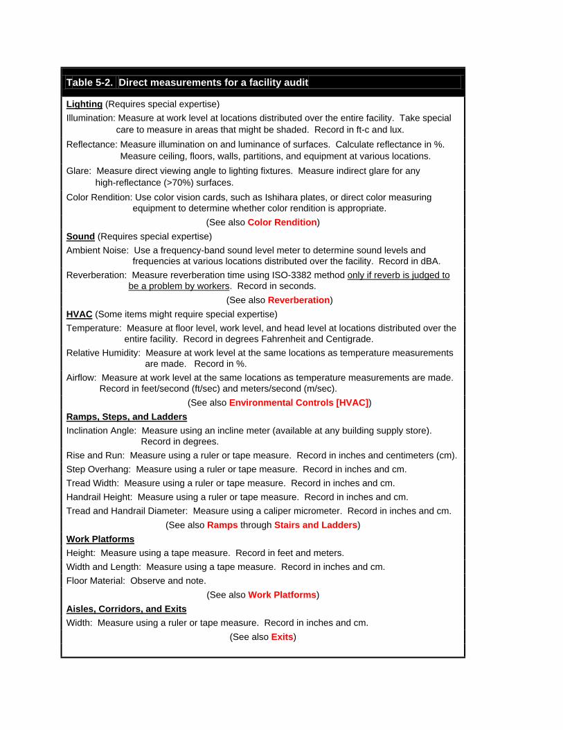
Table 5-2. Direct measurements for a facility audit
Lighting (Requires special expertise)Illumination: Measure at work level at locations distributed over the entire facility. Take special
care to measure in areas that might be shaded. Record in ft-c and lux.Reflectance: Measure illumination on and luminance of surfaces. Calculate reflectance in %.
Measure ceiling, floors, walls, partitions, and equipment at various locations.Glare: Measure direct viewing angle to lighting fixtures. Measure indirect glare for any
high-reflectance (>70%) surfaces.Color Rendition: Use color vision cards, such as Ishihara plates, or direct color measuring
equipment to determine whether color rendition is appropriate.(See also Color Rendition)
Sound (Requires special expertise)Ambient Noise: Use a frequency-band sound level meter to determine sound levels and
frequencies at various locations distributed over the facility. Record in dBA.Reverberation: Measure reverberation time using ISO-3382 method only if reverb is judged to
be a problem by workers. Record in seconds.(See also Reverberation)
HVAC (Some items might require special expertise)Temperature: Measure at floor level, work level, and head level at locations distributed over the
entire facility. Record in degrees Fahrenheit and Centigrade.Relative Humidity: Measure at work level at the same locations as temperature measurements
are made. Record in %.Airflow: Measure at work level at the same locations as temperature measurements are made.
Record in feet/second (ft/sec) and meters/second (m/sec).(See also Environmental Controls [HVAC])
Ramps, Steps, and LaddersInclination Angle: Measure using an incline meter (available at any building supply store).
Record in degrees.Rise and Run: Measure using a ruler or tape measure. Record in inches and centimeters (cm).Step Overhang: Measure using a ruler or tape measure. Record in inches and cm.Tread Width: Measure using a ruler or tape measure. Record in inches and cm.Handrail Height: Measure using a ruler or tape measure. Record in inches and cm.Tread and Handrail Diameter: Measure using a caliper micrometer. Record in inches and cm.
(See also Ramps through Stairs and Ladders)Work PlatformsHeight: Measure using a tape measure. Record in feet and meters.Width and Length: Measure using a tape measure. Record in inches and cm.Floor Material: Observe and note.
(See also Work Platforms)Aisles, Corridors, and ExitsWidth: Measure using a ruler or tape measure. Record in inches and cm.
(See also Exits)

Questionnaires/OpinionnairesDirect measurements tell us whether certain facility conditions are within the recommended
range. They don't tell us whether the workers believe that these conditions, or other facilityfeatures, cause them problems during their work; also, they won't tell us whether the assumptionsused to develop the recommendations are realistic. By using questionnaires and opinionnaires,we can ask workers to tell us how they feel about various facility features and how they workand dress. Used in this way, questionnaires can help identify faulty assumptions and potentialproblem areas within the facility.
Table 5-3 is an example of a combined questionnaire/opinionnaire that you can use during afacility audit. This table is partly adapted from work done by Koli and Drury.37 It contains itemsthat ask for specific information, items that ask for opinions, and a final item that serves as acritical incident report. Note that the name, job title, and other fields that might be used toidentify individual workers are completely optional. Allowing respondents to remain anonymousincreases the chance that you will get information that reflects reality, rather than what workersthink you want to hear.
Table 5-3. Example of a questionnaire for use during a facility audit
FACILITY AUDIT QUESTIONNAIRE
------Identification/Demographics------
(All information in this section is optional.)
Name:_______________________________ Job Title:______________________________
Gender: ___M ___F Age: ______ years Height: ____ft. ____in. Weight: ____lbs.
------HVAC------
1. How would you rate the overall physical effort normally associated with your job? Circle one.
low moderate high
2. From the chart below, please circle those items of clothing you normally wear at your job. Ifyour clothing changes depending on the weather, indicate hot weather clothing with an "H" andcold weather clothing with a "C".
Men Women
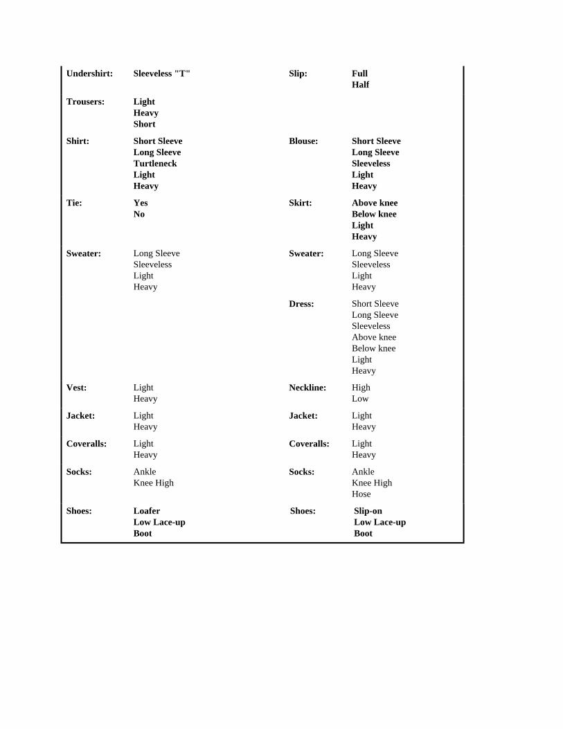
Undershirt: Sleeveless "T" Slip: FullHalf
Trousers: LightHeavyShort
Shirt: Short SleeveLong SleeveTurtleneckLightHeavy
Blouse: Short SleeveLong SleeveSleevelessLightHeavy
Tie: YesNo
Skirt: Above kneeBelow kneeLightHeavy
Sweater: Long SleeveSleevelessLightHeavy
Sweater: Long SleeveSleevelessLightHeavy
Dress: Short SleeveLong SleeveSleevelessAbove kneeBelow kneeLightHeavy
Vest: LightHeavy
Neckline: HighLow
Jacket: LightHeavy
Jacket: Light Heavy
Coveralls: LightHeavy
Coveralls: LightHeavy
Socks: AnkleKnee High
Socks: AnkleKnee HighHose
Shoes: LoaferLow Lace-upBoot
Shoes: Slip-onLow Lace-upBoot

Table 5-3. Example of a questionnaire for use during a facility audit (cont.)
3. As far as being warm or cool, how do you feel right now? Place and "X" anywhere along thisscale.
1 2 3 4 5 6 7|------------------|-------------------|------------------|------------------|------------------|------------------|
hot warm slightly neutral slightly cool cold warm cool
4. How would you like to feel right now? Circle one. Warmer no change cooler
5. How do you feel during summer? Place an "X" anywhere along this scale.
1 2 3 4 5 6 7|------------------|-------------------|------------------|------------------|------------------|------------------|
hot warm slightly neutral slightly cool cold warm cool
6. How would you like to feel during summer? Circle one. Warmer no change cooler
7. How do you feel during winter? Place an "X" anywhere along this scale.
1 2 3 4 5 6 7 |------------------|-------------------|------------------|------------------|------------------|------------------|
hot warm slightly neutral slightly cool cold warm cool
8. How would you like to feel during the winter? Circle one. Warmer no change cooler
------Lighting------
9. Do you wear corrective lenses while you are working? Yes No
10. If you circled "Yes" in Item 9, what type of lenses do you wear? Circle all that apply. Single Rx glasses Bifocals Trifocals Contacts
11. When working outside an aircraft, do you often have to use extra lighting to perform yourwork? Yes No
12. If you circle "Yes" in Item 11, what type of extra lighting do you use? Circle all that apply. Flash light Light stand Drop light Head-mounted light
13. Do you sometimes have trouble reading written procedures because there's not enoughlight? Yes No

Table 5-3. Example of a questionnaire for use during a facility audit (cont.)
14. While working outside an aircraft, have you ever had difficulty identifying a color ortelling one color from another? Yes No
15. Are you aware of having any visual color weakness (color blindness)? Yes No
16. Do you often experience glare from the hangar lights? Yes No
------Audio Communication------
17. Do you normally wear earplugs or earmuffs? Yes No
18. Do you have difficulty understanding messages on the PA system? Yes No
19. Do you have difficulty talking with other workers who are in your immediate work area?Yes No
20. What is the maximum distance that you need to communicate by voice (without phonesor radios)? _________feet
21. Do you have difficulty understanding people on the radio or telephone when you areinside the hangar? Yes No
22. Have you ever been told by a doctor or medical technician that you have any degree ofhearing loss? Yes No
------Access------
23. Have you ever had difficulty getting up or down any of the fixed stairs, ramps, or laddersin the hangar? Yes No
24. If you circled "Yes" in Item 23, please indicate with which stair(s), ramp(s), or ladder(s)you haddifficulty________________________________________________________________
25. Do you ever drive a forklift or tug as part of your job? Yes No
26. If you circled "Yes" in Item 25, have you had any difficulty maneuvering that equipmentin the hangar aisles? Yes No
27. Have you ever had difficulty getting into or out of your work area? Yes No
28. Have you ever had difficulty finding another area or workplace in the hangar? Yes No
29. Have you ever taken part in an emergency evacuation of the hangar-either a drill or thereal thing? Yes No
30. Have you ever had difficulty getting out of the hangar in emergency conditions? YesNo

Table 5-3. Example of a questionnaire for use during a facility audit (cont.)
------Work Platforms------
31. When you have to work on a platform or scaffold, how much room is there for you and yourtools? Place an "X" anywhere along this scale.
1 2 3 4 5 6 7 |------------------|-------------------|------------------|------------------|------------------|------------------|
totally pretty slightly adequate some room ample room wide inadequate crowded crowded to spare to spare open
32. Have you ever slipped on the floor of a work platform or scaffold? Yes No
33. Is slipping a common problem? Yes No
34. Have you ever overloaded a work platform? Yes No
------Critical Incident------
Have you ever seen or been involved in any accident or near accident that you think wascaused, even partly, by the way the hangar itself is designed? If so, please briefly describe theevent and what you think contributed to it.
________________________________________________________________________________
________________________________________________________________________________
________________________________________________________________________________
________________________________________________________________________________
________________________________________________________________________________
________________________________________________________________________________
________________________________________________________________________________
________________________________________________________________________________
________________________________________________________________________________
________________________________________________________________________________
________________________________________________________________________________
(Use the back of the page, if you need more room.)

Thank you for your help. The information on this questionnaire will be combined with theinformation on all other questionnaires. We will not attempt to associate any response with you,personally. If you give us your name, we might contact you to give us more details about someof the information you supply. However, in no case will the information you give us be used inany way related to your performance review, pay scale, promotions, etc.
Structured InterviewsAfter you analyze the information provided by questionnaires, there are likely to be a number
of topics that need to be explored in greater detail. Structured interviewing is a good method foraddressing certain subject areas in depth. The specific subjects that you need to cover duringinterviews depend on feedback obtained from the questionnaires and the direct measurements, ifthey are done. However, the structured interviews will take on the general topical outline of thequestionnaire forms, i.e., the type of information to be gathered is pretty much the same.
Structured interviews provide the flexibility of a person-to-person conversation, alsoallowing the people being interviewed to interact with one another. This helps bring out ideasand information that might be forgotten if they responded to a questionnaire. The majordisadvantage of structured interviews is that they are subject to the interpersonal dynamics ofany group discussion. People with strong personalities tend to dominate such discussions, eventhough the information they provide is typically no better than that of people with more retiringpersonalities.
To compensate for the effects of various personalities in an interview setting, a facilitatorneeds to be present to steer the discussions in the proper direction and to mediate anydisagreements that arise. The facilitator should be someone who is trained in interviewingtechniques and who is not part of the participants' organization. Table 5-4 shows a typicaloutline for a facility-related structured interview. There can be several interviews conducted withdifferent participants. Ideally, each interview should include between 6 and 12 people, notincluding the facilitator.
Structured interviews should last about one-half day, and the output should be theresponsibility of the facilitator (or a secretary assigned to the interview). The products of aninterview should consist of written notes covering the essence of what participants discussed ordecided.38 Generally, the participants' identities should not be associated with the output of theinterview. It is not a good idea to record structured interviews on audio or video tape. Recordersmake the participants nervous and reviewing the recordings is very time-consuming.

Table 5-4. Typical topical outline for structured interview.
Introduction of Facilitator and Participants
Purpose of the Interview
Rules of the Interview
Description of the Facilities to be Discussed
Temperature, Humidity, and Airflow
Noise Levels and the Ability to Communicate
Lighting
Stairs, Ramps, and Ladders
Work Platforms
Aisles, Exits, and General Access
Critical Incidents
Summary
Checklist WalkthroughUsing the methods we've already discussed, it's possible to gather a lot of facility
information. However, it's also possible to miss a lot. The main problem with these activities isthat we have to know which questions to ask before we begin the activity. If we fail to asksomething important, we might or might not get data associated with that issue. Also, in theinterest of efficiency, we have intentionally left certain information out of the previous methods.The walkthrough addresses both the issue of asking the right questions and gathering the datathat were left out of the other activities.
A facility review team conducts a facility walkthrough. The team is composed of essentiallythe same types of people as the Facility Review Group, with the addition of a human factorsperson. The review team actually walks through the maintenance facility with a structuredchecklist. The information they seek is keyed to the checklist. The big advantage a humanreview team offers is that they can notice things that aren't on the checklist. While the checklistprovides structure, it doesn't close out examining other aspects of the facility that might catchteam members' attention.
An example of a structured walkthrough checklist is provided in Table 5-5. This checklist ispartly adapted from work done by Koli and Drury.37,39 Each team member should carry a copyof the checklist while conducting the walkthrough. One member of the team, or an assignedsecretary, should keep the "official" team notes. However, each review team member should alsojot down a short note regarding any facility feature they find either significantly good or bad.

This checklist is a bit misleading, since it tacitly assumes that each topic area, such as"Lighting," will be addressed in serial order. In fact, this would be an inefficient way to conducta walkthrough. What is more likely is that the review team will start in one part of the facility.They will examine every applicable topic for that area before moving to another area. Theyrepeat this process until all relevant facility locations have been examined. Given the nature ofthis process, it is a good idea to make several copies of the checklist and to use one copy for eacharea to be audited.
It might be necessary to conduct multiple walkthroughs to observe the facility in several ofits common operational modes. For example, perhaps it is advisable to walk through once duringthe daytime and once at night. Also, it might be wise to walk through once during the summerand once during the winter. Of all the activities related to facility audits, walkthroughs areprobably the most appropriate to conduct periodically throughout the year.
After a round of walkthroughs is completed, the facility review team should meet to discussits findings. In fact, the facility audit team, which might be the same as the review team, shouldmeet to discuss the results of all audit activities. Facility problems should be identified,discussed, and prioritized. A plan should then be devised for addressing the highest-priorityissues.

Table 5-5. Structured walkthrough checklist
General Observations
1. Is the area generally clean and free of trash, obstructions, and debris?
2. Are aisles and walkways clearly marked and clear of obstructions?
3. Is the signage adequate to convey a sense of location?
4. Have workers modified any of the signs or made signs of their own?
5. Are storage areas being used as intended?
6. Is there an obvious, well-marked exit from the area?
7. Are there well-marked parking areas for forklifts and tugs? Is the equipment parked there?
Lighting
8. Does the lighting appear to be fairly even in the area, or are there bright and dark spots?
9. Is there any noticeable flicker from the lighting system?
10. Are all of the facility lights in working order?
11. Have workers modified the light fixtures?
12. Are there battery-powered emergency lights near exits, stairs, and ramps?
13. Are technicians bending over their work to obtain a closer view?
14. Is supplemental task lighting being used in the area? Why?
15. Is there any obvious glare from the facility lights? Where and what type?
16. Do colors appear to be natural, or do they look strange?
17. Are light controls clearly marked and easy to reach?
Ramps, Stairs, and Ladders
18. Are there handrails on all ramps, stairs, and fixed ladders?
19. Is the cross-section of all handrails circular? If not, what shape are they?
20. Are all stair and stair ladder treads covered with non-slip material?
21. Are all landings covered with non-slip material?
22. Do open stairs and ladders have safety screens behind them?
23. Do all portable ladders have non-skid feet?

Sound and Noise
24. Can you understand what is being said on the PA system?
25. Have any PA speakers been modified by workers?
26. If hearing protection is required, are all people in the area wearing it?
27. Can you converse with someone 4 feet away without raising your voice?
28. Have any equipment enclosures been removed or left open?
29. Can you converse on the telephone and understand the person you are calling?
30. Can you converse on the radio and understand the person you are talking with?
31. Are workers using equipment that emits audio signals?
HVAC
32. Do you feel hot or cold?
33. Can you tell a difference in temperature between your head and your feet?
34. Is there any detectable air movement in the area? Is there too much?
35. Are supplemental fans or blowers being used in the area?
36. Are supplemental heaters being used in the area?
37. Is the area exposed directly to the outside?
38. Does it feel particularly humid in the area?
39. Can you detect any noxious smells or "chemical" odors in the area?
Miscellaneous
40. Have workers complained to you about a specific facility feature in the area?
Facility Change Review
Once the human factors basis for a facility has been established, it has to be activelymaintained. That is, every substantive change made to a facility needs to be reviewed to makesure it doesn't degrade the facility's usability. Experience in other industries, especially innuclear power plant control rooms, has demonstrated that without active change control thedesign basis tends to degrade over time.
There are many methods to review facility changes. One method that will probably workwell in most aviation maintenance organizations is borrowed from the nuclear industry.40 Thismethod requires that a facility review group (FRG) be established. The FRG ensures that anyaddition or modification to the facility is necessary, will not degrade the facility's existingfunctions, and conforms to established design guidelines.
The FRG should be composed of representatives from each of the following groups withinthe maintenance organization:
• Facilities

• Maintenance Planning• Supervision• Crafts• Training• Personnel.
The FRG acts as a reviewer of facility change requests, not as an originator of changerequests. By having "sign-off" responsibility for change requests, the FRG acts as a gate throughwhich any facility change must pass. The FRG examines each facility change request to ensurethat its originator adequately considered certain issues. The FRG should be a standing panelmeeting periodically to review facility change requests.
For the FRG method to work, the basis for their review must be made known to potentialoriginators of facility change requests. The FRG essentially places the burden for consideringhuman factors issues on the person or group requesting a facility change. By publishing theirreview criteria and distributing them through the organization, the FRG heightens everyone'ssensitivity to human factors issues. Increased sensitivity increases the probability that a facilitycan maintain a reasonable human factors design basis throughout its service life.
Table 5-6 provides examples of the types of design considerations that originators of facilitychanges should be aware of. When the FRG meets to consider proposed facility changes, theoriginator(s) of those changes should be present to address any of the FRG's questions. Theresult of an FRG review is an Action Record; an example is shown in Table 5-7. If any questionon the Action Record is answered "No" by the FRG, all further action on the change requestshould be suspended until the originator can address the issue to the FRG's satisfaction.

Table 5-6. Human factors considerations for facility changes.
The following considerations should be addressed by the originator(s) of facility-related changerequests:
1. Does the proposed change(s) or addition(s) have definite and essential operationalpurposes? What are they?
2. Does the operational purpose(s) substantially affect the existing layout or functional designof the maintenance facility?a) How is the proposed operational purpose presently achieved?b) Which existing facility elements are used for this operation?c) What are the alternatives for achieving this operation purpose?d) Was each alternative fully reviewed and evaluated?
3. Is the facility change in this request primarily for use by workers performing maintenancetasks?a) Will the change primarily affect maintenance technicians?b) Will the change affect supervisors and planners?c) Are there any non-maintenance tasks or workers affected?
4. Will any of the proposed changes affect existing facility elements-either during normal oremergency operation?a) Does this change require a substantial change to the facility layout?b) Does this change require new or modified emergency egress routes?c) Does this change require the temporary disruption of an existing work area?
5. Are there regulatory requirements for this proposed change or addition?
6. Does the change conform to established human factors principles and guidelines?
7. Does the change retain the functional grouping of facility elements?
8. What are the training requirements associated with this change? What are the timeconsiderations for training?
9. What procedure and other document changes are required to accommodate this change?10. What effect, if any, will the proposed change(s) have on the following facility characteritics:
a) Sound levelsb) Light levelsc) Aisle widthsd) Work platformse) HVACf) Fire protection

Table 5-7. Example design for a Facility Review Group Action Record.
Facility Review Group (FRG)Action Record
CN Number:_______________________
Proposed change presented by:______________________________
1. Was the purpose and scope of the proposed change adequately presented? YES NO
2. Was the necessity for the proposed facility change established? YES NO
3. Was the effect on existing maintenance operations satisfactorily addressed? YES NO
4. Were the training requirements adequately addressed? YES NO
5. Were procedural and operational changes adequately addressed? YES NO
6. Were the effects of the change(s) on facility maintenance adequately addressed? YESNO
7. Were provisions made to ensure compliance with Human Factors guidelines? YES NO
FRG Action:
Shall the proposed change be approved?Supervision YES NOPlanning YES NOCrafts YES NOTraining YES NOFacilites YES NO
Disposition:Acceptable YES NO
Remarks:__________________________________________________________________________________________________________________________________________________________________________________________________________________________________________
Action Record by: ___________________________Date:________________________________
Facility Standards
Establishing facility design standards is somewhat tricky. On the one hand, standards serve auseful purpose by giving designers consistent design rules that ensure a minimum level ofusability. On the other hand, standards lock designers into doing things in a way that may not bebest for all situations. The following guidelines address some of the most fundamental facilitydesign issues. They present values that are not likely to change frequently, since they are tiedeither to human physiological performance or to established regulatory policies.

These recommendations are derived from a number of sources, including applicable OSHAregulations,15 Wesley Woodson's Human Factors Design Handbook,41 Alvin Tilley's TheMeasure of Man and Woman,42 and MIL-HNDBK-759B.43 Where multiple recommendationsexisted, these were selected and combined to provide a reasonable range of dimensions. WhereOSHA regulations are specific and prevailing, those values are used. No recommendation in thissection violates an OSHA requirement.
Aisles and CorridorsPeople move along certain paths in a facility. In open areas, these pathways are called aisles.
In walled areas, people move along corridors. The fundamental guidance for aisles, corridors,and ramps is that they have to be (a) unobstructed and (b) wide enough to accommodate thetypes of traffic they will support. Figure 5-9 illustrates recommended widths for various types ofaisles and corridors.
Figure 5-9. Recommended width for aisles and corridors.
When equipment is routinely moved along aisles and corridors, the pathway must be wideenough to allow people and equipment to use it simultaneously. In some cases, two pieces ofequipment must be able to pass in the aisle. A common industrial requirement is for aisles toaccommodate forklifts or tugs. Figure 5-10 illustrates the sizing requirements for aisles andcorridors that must be used by people and equipment.

Figure 5-10. Aisle and corridor width forequipment and people

Figure 5-11. Aisle and corridor width whenequipment maneuvering is required
Of course, the recommended dimensions shown in Figure 5-10 don't guarantee that there isenough room for any particular type of equipment to maneuver. Where equipment must turnaround or handle loads within an aisleway, use the recommendations in Figure 5-11. Theserecommendations result in aisles with enough room for people to move around equipment, evenequipment stuck crossways in the middle of the aisle.
RampsRamps provide a smooth transition between two floor elevations. There are a number of
reasons for using ramps instead of stairs, including accommodating wheeled industrialequipment and people with disabilities who cannot negotiate stairs. Both of these purposescannot always be accommodated with a single set of design standards.
OSHA recognizes two different classes of ramps, cleverly named Class A and Class B. Theyvary mainly in their slope and width. Both Class A and Class B ramps are too steep forwheelchair access. The general recommendation for wheelchair ramps is for the slope not toexceed 1 in 12, nor for the longest run to a landing to exceed 30 feet. In addition, OSHAregulations require that any powered industrial truck driven up or down a ramp with a slopeexceeding 10% be driven with the load upgrade.
Figure 5-12 shows ramp dimensions that accommodate both powered equipment and

wheelchair users.
Figure 5-12. Ramp dimensions that will accommodate powered equipment and wheelchairs
ExitsThe major concern of any facility designer should be the safety of the people who will be
using the facility. Aside from the implications associated with the facility's structural integrity,the most obvious safety concern is people's ability to get out in an emergency. In OSHAterminology, this safety factor is known as "emergency egress." The most oft-cited situationrequiring emergency egress is a fire. This is the most common actual situation, as well.
An individual egresses by leaving the facility via an exit. OSHA distinguishes three separatecomponents of an exit: the exit access, the exit itself, and the exit discharge. There are manyrequirements associated with exit components such as the necessity of maintaining clean andunobstructed paths both to and from exits. The design characteristics most relevant to this Guideare the required exit dimensions.

Figure 5-13. Minimum exit requirements andegress capacity calculation
The requirement for an exit's width is directly linked to the number of people who mighthave to use it in an emergency. "Exit," as used here, means all three parts of the exit. OSHA hasprovided a formula for determining the required width of an exit. A "unit" of exit width isdefined as 22 inches. Fractional units cannot be counted, except for adding 12 inches (one-halfunit) to one or more full unit. Each unit of exit width has the capability of accommodatingbetween 60 and 100 facility occupants. Flat routes and Class A ramps can accommodate 100people per unit of exit width. Class B ramps can accommodate only 60 occupants.
In addition to the exit capacity calculation, there is a requirement that any exit must have aminimum width of 28 inches and a minimum ceiling height of 7 feet 6 inches. Figure 5-13graphically depicts these exit requirements.
Stairs and LaddersAnother way of moving between floor elevations is to use stairs or ladders. Actually, a range
of devices can be used to bridge two elevations. The preferred device depends on the verticaldistance to be spanned and the available horizontal distance within which the transition can bemade. OSHA allows fixed stairs to be angled between 30 and 50 degrees from the horizontal.Portable ladders should be placed at an optimum angle of 75 degrees from horizontal. Fixedladders can be placed between 75 and 90 degrees from horizontal.
As a practical matter of comfort and energy expenditure, fixed stairs should be angledbetween 30 and 35 degrees from the horizontal. Spanning the angular range of between 35 andabout 75 degrees are special industrial stairs called "stair ladders." In the aviation workplace,stair ladders would most likely be used as part of portable or fixed work platforms. In the rangeof about 68 to 80 degrees, portable ladders are the best bet. Beyond this range, use fixed ladders.
Figure 5-14 shows the angular ranges for different types of vertical transitions. In choosing aparticular transition method, keep in mind that OSHA doesn't allow portable ladders to be usedfor routine, i.e., frequent or everyday, movement of people or materials.
Figures 5-15 through 5-18 show the recommended dimensions for fixed stairs, stair ladders,
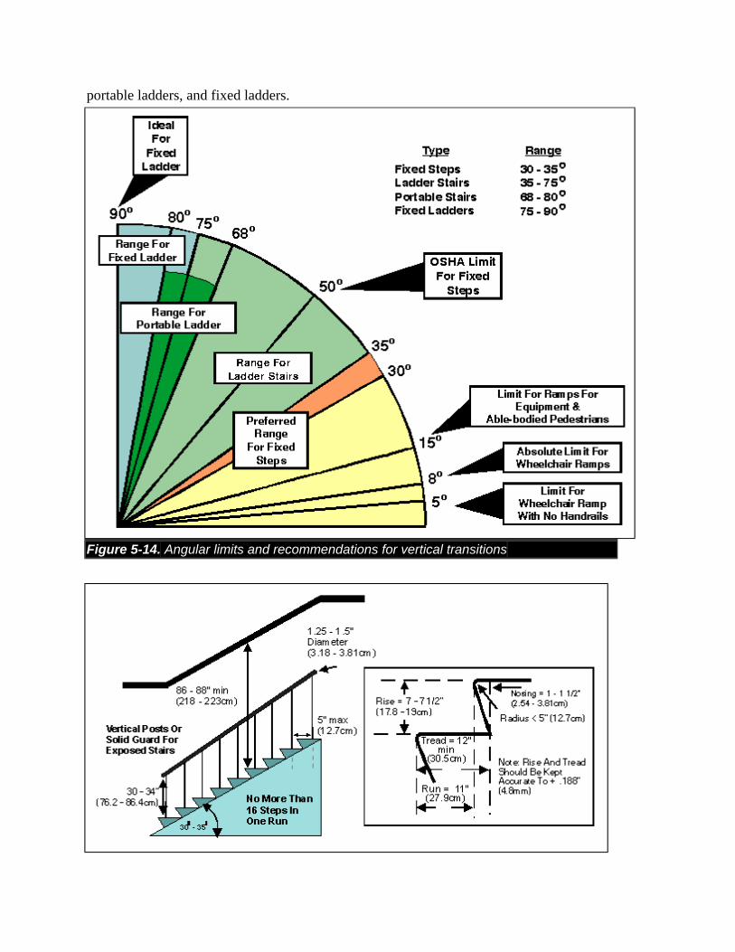
portable ladders, and fixed ladders.
Figure 5-14. Angular limits and recommendations for vertical transitions

Figure 5-15. Recommended dimensions for interior stairs
Figure 5-16. Recommended dimensions for stair ladders

Figure 5-17. Recommended dimensions for portable ladders
Figure 5-18. Recommended dimensions for fixed ladders
Work PlatformsAviation maintenance facilities use a number of different work platforms. These platforms
enable technicians and inspectors to get close enough to aircraft parts to do their jobs. In most

cases, work platforms are elevated above ground level. The act of getting up to and down fromwork platforms is addressed by the recommendations for stairs and ladders. However, workplatforms themselves have characteristics that are subject to human factors design principles.
There are three important human factors aspects of work platforms: overall size,conformance to the work area, and guarding against falls. Of these characteristics, only theoverall size of the platform depends on the tasks to be performed and the workers performingthem. For example, the work area required by a single individual dressed in normal work clothesand carrying a few tools is much less than that required by several workers dressed in bulkyprotective clothing and using large test equipment. Also, a worker in a wheelchair requires morearea than a standing worker.
Conformance and guarding can be considered to be universal requirements, regardless of thetask. For example, if the platform is located 10 feet or more off the floor, safety harnesses shouldbe used in addition to guard rails --regardless of the task(s) being performed. Figure 5-19 showsthe recommended dimensions for each aspect of work platforms.
The floor of a work platform should either be made of, or coated with, a non-slip materialsuch as expanded metal or abrasive tile (respectively).
Figure 5-19. Recommended dimensions andfeatures of work platforms
Environmental Controls (HVAC)The issue of establishing a safe and comfortable working environment might seem
conceptually simple. The heart of the matter is maintaining a worker's internal body temperature,the so-called "core" temperature, within a certain narrow range. We know a lot about how

various environmental and work factors affect body temperature. For example, we know thatboth the core temperature and the subjective feeling of comfort are affected by air temperature,radiant heat, humidity, air velocity, type of work, and clothing. Thus, for specific jobs andworkers, we can analyze these factors and determine the appropriate range for each factor.
Figure 5-20. Thermal comfort zone for typicalhangar-type work
While establishing a comfortable work environment is fairly straightforward for individualjobs and tasks, it is not so easy for an entire facility. In a maintenance hangar, different types ofjobs are being performed simultaneously. Therefore, a comfortable environment for a technicianperforming eddy current testing on a wing skin might not be the same as a comfortableenvironment for a mechanic drilling and riveting inside an aircraft. About the best we can dofrom a facility standpoint is to try to keep its atmospheric variables within a reasonable envelope.
Once the envelope is established, we have to depend on the workers to alter their clothing ortheir local workspaces to account for major departures from our assumptions. Figure 5-20shows a commonly accepted thermal comfort zone.16,25,44 These values apply to work periodsof up to 8 hours. For extended work beyond 8 hours, the comfort zone should be pulled inslightly (by about 1 degree F on each side).
LightingWorkers' ability to perform various types of maintenance and inspection tasks largely
depends on appropriate lighting in their work areas. Lighting is characterized by its intensity andits color rendering ability. Lighting can also be characterized as "facility" or "task" lighting.

Facility lighting is the illumination provided by the common facility lighting system, includinglight fixtures and windows. Task lighting is illumination supplied for a specific task. It includesdrop lights, portable light stands, interior aircraft compartment lights, and flashlights.
Intensity. In the aviation maintenance domain, proper facility lighting is particularlyimportant. Most scheduled maintenance is done inside a hangar during nighttime hours. Theintensity of illumination is measured in lux, which is the metric equivalent of the foot-candle(ft-c). Each foot-candle is equal to about 10 lux. The level of illumination that is "adequate"depends on the type of task being performed. To give an idea of the range of "adequate"illumination, consider the following:• OSHA requires that EXIT signs be illuminated with no less than 5 ft-c (about 50 lux). • Difficult inspection tasks or fine bench work can require illumination of up to 500 ft-c (5000
lux).Even for general facility lighting, there is no single minimum illumination that can be cited
as appropriate. Some experts recommend that infrequently visited areas such as storage roomscan be lit sufficiently with as little as 15-20 ft-c (150-200 lux).45 However, if we assume that itis not desirable to have to provide supplemental lighting for every task being performed in ahangar, the overall illumination level should be maintained at between 75 and 100 ft-c (750-1000lux).46,47,48
Distribution. It is important to keep light levels fairly even throughout the work areas. Themost common recommendation is to keep the ratio of highest to lowest illumination in andaround a work area to 3-to-1 or less.48 In general, we want to provide even, diffuse,shadow-free, glare-free illumination in all areas of a facility used by people. The best way todiffuse light and minimize shadows is to use a large number of small light sources rather than afew large fixtures. By itself, however, the placement of fixtures will not eliminate shadows orbright spots.
Regardless of the placement of light fixtures, the floor area beneath the wing of a largetransport aircraft is likely to be shielded from full direct lighting. To raise the illumination levelin such areas, the hangar's ceiling, walls, floors, and fixed equipment must be painted so thatthey reflect a good part of the light falling on them. Reflectance is normally specified in"percent." A reflectance value of 50% means that the surface reflects half of the light falling onit. Figure 5-21 shows the recommended reflectance values for these facility elements.48

Figure 5-21. Recommended reflectance values for facility elements
Glare. Preventing glare is a prime concern in hangar lighting design. There are two types ofglare-direct and indirect. Direct glare occurs when people look directly at light sources, eitherwindows or light fixtures. Indirect glare is caused by light reflected from highly reflectivesurfaces. Figure 5-22 illustrates both types of glare. The problems caused by direct glareincrease as the light sources get closer to a viewer's normal line of sight. The worst performanceproblems occur when a light source is directly in the viewer's line of sight. These problemsdecrease as the light source is raised above the line of sight. The so-called "direct glare zone" istaken as that between 0 and 45 degrees above the line of sight. In practice, light sources shouldbe placed at the highest available angle to the viewer's line of sight.23,25
Because of the high clearances found in aircraft maintenance hangars, most light fixtures areplaced well above the floor. By a judicious selection of fixture type, diffusers, reflectors, etc.,direct glare problems can be minimized. Figure 5-23 shows the recommended viewing anglesthat will prevent direct glare problems. It also shows an example calculation of the horizontaland line-of-sight distance of an observer from a fixture that meets the recommended viewingangle criterion.

Figure 5-23. Recommended viewing anglesto avoid direct glare

Figure 5-22. Direct and indirect glare
The effects of indirect glare, while not generally as debilitating as those of direct glare, candrastically reduce performance. Indirect glare is relatively easy to control, however, by coatingreflecting surfaces with flat paint, by moving light sources out of locations where they causereflections, or, if light sources can't be relocated, by equipping them with diffusers or polarizinglenses.
Color. The final issue related to lighting is color rendition. Different types of light sourceshave varying abilities to render certain colors. Natural daylight has the best color renderingability, since it contains all natural (spectral) colors. Each artificial light source emits a particularspectrum of light.45 That is, each source contains more of some colors than others. For example,mercury vapor lights have very little red in their spectrum. An object such as an electrical wirethat appears red in daylight appears orange (or even black) when viewed under a mercury vaporlight.
The basic problem for designers is that the lights providing good color rendition, such asincandescent bulbs, tend to be very inefficient. Efficient light sources convert a given amount ofelectrical power to more visible light than inefficient sources. Conversely, lights that tend to bevery efficient, such as high-pressure sodium, are notoriously poor at reproducing certain colors.

Daylight fluorescent lights, which are fairly good at reproducing colors, are in the middle of theavailable efficiency range.
There are two approaches to solving the color-rendering problem. The first is to use a largenumber of light fixtures and to mix them among at least two different, high-efficiency, types. Forexample, alternating mercury vapor and high-pressure sodium lamps provides a broad colorspectrum at the hangar's working level. The second approach is to use a very efficient type oflighting for the overall facility, regardless of its color rendering capability and to supplementcolor-sensitive tasks with task lighting. The task lighting to be chosen must have a broadcolor-rendering capability.
This section has covered a lot of recommendations related to lighting. These issues arecondensed in Table 5-8. Findings and specific recommendations for task lighting, includingflashlights and larger portable lights, can be found in reference 12.
Sound and NoiseMuch of the information that aviation maintenance technicians and inspectors need to do
their jobs comes to them in the form of audio communications. We include in this categoryperson-to-person voice exchanges, telephonic transactions, information received via radio andpublic address links, and audio tones from test equipment or automatic monitoring systems.
Table 5-8. Recommendations related to facility lighting.
Lighting Levels
Lowest recommended level: 15-20 ft-c (150-200 lux) Should be used only forinfrequently used areas
Normal recommended level: 75-100 ft-c (750-1000 lux) Adequate for many normalmaintenance tasks
Illumination Ratio
Maximum recommended ratio: 3-to-1 Brightly lit areas no more than 3 timesthe illumination of dimly lit areasnearby
Distribution of Illumination
Use a large number of regularly-spaced small lights rather than a few large lights
Recommended reflectance of various surfaces: Ceiling -Walls and partitions -Floors -Equipment -
80-90%40-70%40%25-45%
All finishes should be matte
Glare Prevention

Direct Glare: Place lights so they are at least 45 deg. above the horizontal line of sight. 60deg. is better.
Indirect Glare: Place lights so they are not in the reflected viewing path.
Color Rendition
Try to balance the color spectrum of lighting. Do not use only sodium or mercury vaporlamps. Either mix light types or use deluxe daylight fluorescent.
Measurements - see Table 5-2
Intensity. As we noted in the CONCEPTS section, the intensity of sound, called its soundpressure level (SPL), is measured in decibels. The decibel scale is logarithmic, not linear. Asound that has an SPL of 40 dB is 10 times more intense than a sound with an SPL of 20 dB.Figure 5-24 shows SPLs for some common sounds.
From a facility design perspective, the overall task is to minimize unwanted sounds, whichwe call "noise," and to maximize the probability of workers being able to hear required audioinformation. OSHA regulations define a worker's noise exposure in terms of "dosage," based onthe well-tested premise that the effects of noise exposure are cumulative and increase inproportion to the time-weighted average (TWA) of the worker's exposure. For workers whoincur an 8-hour noise dose equivalent to 85 dBA, companies must begin an active program ofhearing conservation. The "A" in dBA means the noise is measured using a particular spectralweighting (the A-scale) in the measuring instrument. For continuous noise of 90 dBA or above,workers must wear some form of hearing protection device.49

Figure 5-24. Sound pressure levels for some commonsounds
Noise Reduction. There are three opportunities for reducing the noise exposure of individualworkers (see Figure 5-25).50
Noise can be reduced:• At the source• Between the source and the worker• At the worker.
Source noise control is the most attractive of the three methods because we don't have toworry about controlling noise that isn't produced. Source noise control is most effective when itis addressed as a purchasing issue. That is, if we specify that purchased equipment must be quiet,we avoid the problem of noise exposure. If we have to control noise at the worker level by usinghearing protection devices, then we have essentially conceded that we cannot control ambientnoise in the facility. Therefore, only the noise control method of focusing between the sourceand the worker can be addressed with facility design.
There are three ways of reducing noise between the source and the worker: location,

insulation, and reflective absorption.51,52 These methods are summarized in Table 5-9. Theycan be used alone or in combination.
Location refers to placing noise-producing equipment away from the place(s) where workersare located. A common example of this method is locating air compressors outside buildings andrunning compressed air lines to locations where they are needed.
Figure 5-25. Methods for reducing facility noise
Insulation is conceptually simple. It amounts to putting sound-absorbing material betweenthe noise source and the worker. The sound waves must pass through this material to reach theworker. Also, certain types of equipment can be mounted on vibration isolators, which reducethe sound coupling between the equipment and the facility.
Table 5-9. Methods for reducing facility noise.

Method Description
Location Place noise-producing equipment far away from locations whereworkers are performing their jobs.
Example: Placing air compressors outside the facility
Insulation Place sound-absorbing material between the noise source and theworkers. Isolate the noise source from the structure of the facility.
Example: Mount rotating equipment on vibration isolators.Surround equipment with enclosed, sound-absorbing housings.
Reflective Absorption Place sound-absorbing materials on large, flat, and hard reflectingsurfaces, such as ceilings, walls, and floors.
Example: Use acoustic tile on suspended ceilings. Mount eggcratefoam panels on walls
Reflective absorption is a fancy term for putting sound absorbing materials on walls,ceilings, floors, and other surfaces that can reflect sounds. Large, flat, hard surfaces reflectsounds that are directed toward them. Reducing the reflected sound levels can significantlyreduce the overall facility noise level. A common absorptive material is foam rubber shaped intoan eggcrate or honeycomb.
The final method of reducing noise is to provide workers with some type of hearingprotection device (HPD). If the noise SPL is 90 dBA or higher in a particular area, OSHAregulations require the use of HPDs. The most common types of HPDs include plugs insertedinto the ear canal, caps which seal the ear canal near the outside opening, and muffs whichcompletely enclose the outer ear. Two common complaints regarding HPDs are that they areuncomfortable and that they interfere with speech communication.
The effectiveness of HPDs has been shown to decrease significantly because of users'inability to properly insert them into the ear canal.53 A recent study has also shown that HPDscan interfere with speech. Ironically, those HPDs that provide the greatest protection at highnoise levels also interfere with speech at lower noise levels.54 Newer hearing protectiontechnologies such as active noise cancellation are under development now and might reduce oreliminate some of these problems.55
Workers' ability to transmit and receive audio information depends on two factors: lowoverall noise level and intelligibility of the audio sources. We've already discussed ways ofreducing noise levels in a facility. Making audio systems intelligible is another matter entirely.
Facility elements that relate to audio systems include public address (PA) systems and"quiet" locations that can be used for telephonic or radio communication. Three characteristicsdetermine the intelligibility of public address systems: loudness, frequency reproduction, andreverberation.
Loudness. Loudness is the subjective impression associated with the objective SPL of a

sound. Loudness does not correspond directly to SPL. That is, a sound with an SPL of 80 dBAwill not necessarily be perceived as one-third louder than a sound with an SPL of 60 dBA. To beheard and reliably understood, speech has to be about 10 dB above ambient noise levels.25
Frequency. Human speech is not spread evenly across all sound frequencies. Instead, it isconcentrated at frequencies between about 200 and 4000 Hz. Public address systems thatemphasize speech (as opposed to other audio signals) must concentrate their power in thesefrequencies.
Reverberation. Reverberation is a phenomenon that prevents sounds from decaying asrapidly as they should. The common perception of reverberation is the familiar "echo" present inairline terminals, auditoriums, etc. Reverberation is characterized by its time constant,sometimes called the "reverberation period." The reverberation period is the time it takes for asound to decay 60 dB from its original level.56
As the reverberation period gets longer, its negative effect on speech intelligibility becomesgreater and greater. The acceptable reverberation period increases as the volume of the facilityincreases. Figure 5-26 shows how the acceptable maximum reverberation time varies withfacility volume.57 Even for very large volumes, reverberation periods over about 2 seconds areconsidered unacceptable. Reverberation periods of 4-6 seconds render speech almost completelyunintelligible.
Figure 5-26. Acceptable maximum reverberation periods fordifferent volumes. Adapted from Everest, 1978.
In order to preserve these reverberation characteristics in their proper range, facility PAsystems should embody certain features. First and foremost, a PA system should consist of alarge number of small speakers instead of a few large speakers. The speakers and amplifiers

should be designed so that they concentrate most of their output into the range of frequenciesmost common in human speech. The speakers should be mounted so their output fields slightlyoverlap. These design features allow the sound level of each speaker to be set relatively low, andthe overall sound pattern in the facility will be much more even and diffuse. It should be possiblefor a listener walking along a path passing by several speakers not to detect much difference inloudness.
The low power from individual speakers reduces any tendency for reverberation because thesound from any individual speaker decays before it can reflect from surrounding surfaces. If thisdesign is combined with the placement of sound absorption material on large reflecting surfaces,the PA system should be adequately loud and understandable. One exception is workers who arewearing hearing protection. When ambient noise levels are below 85-90 dBA, most hearingprotection devices interfere with understanding speech. At ambient noise levels above thesevalues, PA systems aren't going to be heard anyway.
Even facilities with generally low ambient noise levels might have periods in which noiselevels rise. To accommodate such periods, noise-insulated areas should be provided to allowtelephone and radio communication. These areas can take the form of 3-sided booths or smallenclosed rooms in which ambient noise levels are reduced to below 70 dBA when facility noiselevels are at their highest levels.
Purchase Specifications
The advantages of embedding human factors rules and principles into an organization aredescribed in Chapter 2. In many cases, the biggest impact of integrating human factors intoeveryday operational procedures shows up in the purchasing function. By automatically makinghuman factors requirements a part of every purchase order, maintenance supervisors are freedfrom having to remake decisions for each purchase.
As far as the overall facility is concerned, there are only a few purchasing standards that needto be put in place. These involve stairs, ladders, ramps, surface finishes, and noisy equipment.While there are many other principles and standards that apply to aircraft maintenance tasks,most of these involve individual workspaces, rather than the entire facility.
Stairs, Ladders, and RampsThe recommendations presented in the Facility Standards section of this chapter should be
invoked as a part of each purchase bid and order for such facility components. Simply reproducethe appropriate figures from this document and make them part of your purchase document.
Surface FinishesThe only technical issue related to surface finishes is the reflectance of those finishes. When
a purchase document applies to an interior surface of a maintenance hangar, then it shouldrequire the finish to be matte (flat) and the reflectance to be within the range specified in Figure

5-21. Likewise, if the purchase document involves a piece of equipment to be used in the hangar,its reflectance should be between 25 and 45%.
Equipment Sound LevelsRecall that the best way to reduce overall facility noise levels is to make sure that
noise-producing tools and equipment are as quiet as possible. There are many ways to specifythe sound levels of purchased equipment. Probably the most widely understood method is to usewhat are known as "NC" values. These values come from a series of curves developed over 2decades ago.58 The curves are officially named "preferred noise criterion" (PNC). They specifya maximum SPL across a wide frequency spectrum. Various performance studies have shownthat noise levels not exceeding certain PNC curves are "acceptable" for various activities.
For example, people who work in office environments usually find that noise conditions notexceeding PNC-35 are acceptable. The air conditioning industry uses PNC-35 as its criterion forhow noisy equipment can be. Noise in the PNC-50 to PNC-60 range is barely acceptable forspeech and telephone communication. To ensure that purchased equipment doesn't compromiseworkers' ability to communicate by voice and telephone, adopt a noise standard of PNC-45 inpurchase specifications.
WHERE TO GET HELPThere are at least three sources of help for facility-related issues and questions. The Human
Factors and Ergonomics Society (HFES) is a good source of general human factors information,including that related to facilities. The HFES is located at the address below:
Human Factors and Ergonomics SocietyPO Box 1369Santa Monica, CA 90406Phone: (310) 394-1811Fax: (310) 394-2410Web site: http://hfes.orgEmail: [email protected]
Within the HFES, the Environmental Design Technical Group (EDTG) specializes in "thehuman factors aspects of the constructed physical environment." As of the end of 1997, theEDTG had 164 members. You should note that technical groups of the HFES don't have paidstaff like the overall organization. The Chair of each technical group is a volunteer, electedposition that often changes year to year. The central office of the HFES will always have thelatest information related to technical groups.
For help with specific facility-related measurements, as well as with issues beyond the scopeof human factors, both the National Safety Council (NSC) and the American Industrial HygieneAssociation (AIHA) can be helpful. Industrial hygienists are often responsible for meetingregulatory policies related to noise, air quality, toxic emissions, etc.

Contact the National Safety Council at the following address:National Safety Council1121 Spring Lake DriveItasca, IL 60143-1315Phone: (630) 285-1121Fax: (630) 285-1315Web site: http://www.nsc.org
Contact the AIHA at the following address:American Industrial Hygiene Association2700 Prosperity Ave., Suite 250Fairfax, VA 22031Phone: (703) 849-8888Fax: (703) 207-3561
FURTHER READINGTechnical Handbooks
ASHRAE (1989). ASHRAE handbook-Fundamentals, I-P edition. Atlanta, GA: AmericanSociety of Heating, Refrigeration, and Air-Conditioning Engineers.
Berger, E.H., Ward, W.D., Morrill, J.C., and Royster, L.H. (Eds.) (1986). Noise & hearingconservation manual-Fourth Edition. Fairfax, VA: American Industrial Hygiene Association.
Eastman Kodak Company (1983). Ergonomic design for people at work-Volume 1. New York,NY: Van Nostrand Reinhold.
IES (1987). IES lighting handbook-Application volume. New York, NY: IlluminationEngineering Society.
Salvendy, G. (Ed.) (1987). Handbook of human factors. New York, NY: John Wiley & Sons.
Salvendy, G. (Ed.) (1992). Handbook of industrial engineering-Second Edition. New York, NY:John Wiley & Sons.
Van Cott, H.P., and Kinkade R.G. (Eds.) (1972). Human engineering guide to equipment design,Revised Edition. Washington, DC: US Government Printing Office.
Woodson, W.E. (1981). Human factors design handbook. New York, NY: McGraw-Hill.
Human Factors Textbooks

Bailey, R.W. (1982). Human performance engineering: A guide for system designers.Englewood Cliffs, NJ: Prentice-Hall.
Kantowitz, B.H., and Sorkin, R.D. (1983). Human factors: Understanding people-systemrelationships. New York, NY: John Wiley & Sons.
Konz, S.A. (1985). Facility design. New York, NY: John Wiley & Sons.
Sanders, M.S., and McCormick, E.J. (1987). Human factors in engineering and design, SixthEdition. New York, NY: McGraw-Hill.
Tables and Charts
Tilley, A.R. (1993). The measure of man and woman-Human factors in design. New York, NY:The Whitney Library of Design.
Standards
ISO 6242 (1992). Building construction-Expression of users' requirements. Part 1-Thermalrequirements, Part 2-Air purity requirements, Part 3-Acoustical requirements. Geneva,Switzerland: International Standards Organization.
ISO 8995 (1989). Principles of visual ergonomics-The lighting of indoor work systems-1stEdition. Geneva, Switzerland: International Standards Organization.
SAA AS 2107 (1987). Acoustics-Recommended design sound levels and reverberation times forbuilding interiors. Strathfield, NSW: Standards Association of Australia.
General Safety
ANSI/NFPA 101 (1994). Life Safety Code. Quincy, MA: National Fire Protection Association.
EXAMPLE SCENARIOSThe scenarios below present some of the typical kinds of tasks related to facility design that
you can expect to encounter in the workplace. The purpose of including these scenarios in theGuide is to demonstrate how the authors foresee the document being used. For each scenario, wedescribe how the issues raised in the scenario can be resolved. There is usually more than oneway to approach these issues, so the responses given below represent only one path that Guideusers might take.
As a general rule, always start to look for information by using the Search function. Therewill be instances that you already know where required information is located. However, unlessyou frequently use specific sections of the Guide, you might miss information pertaining to the

same issue located in more than one chapter. The Search will allow you to quickly search allchapters simultaneously.
Scenario 1 - Noise Limits
You've budgeted a certain amount of money for buying new equipment. Included in yourbudget are several pneumatic tools and portable air compressors.
Issues1. How can you determine the noise levels that these new tools and compressors will emit?2. What should you tell the Purchasing Department regarding the noise limits that this new
equipment must meet?
Responses1. This is an issue that will come up again and again. The term "noise levels" in Issue 1 couldeasily be changed to any measurable characteristic for a piece of equipment. For instance, wemight just as well ask how we could determine the illumination level of a particular type of bulb.There are really only two practical ways of determining a physical characteristic: measurementor specification. In the first method, we actually measure the characteristic of interest. In thesecond method, we rely on a vendor's specification to tell us the value of the characteristic.
The Guide addresses the method of direct measurement in the Facility Audit section.Measuring noise levels is described in Table 5-2. Note that some special expertise andequipment is required to perform these measurements. You should also note that thesemeasurements can only be made if the equipment in question is present in the facility oravailable at some other site. This is the drawback of using direct measurement to help defineequipment to be purchased. If the equipment isn't there yet, it's not easy to measure it.
2. The issue of purchase specifications is addressed in the GUIDELINES section. In thesubsection related to equipment sound levels, the Guide briefly describes the existence of"preferred noise criterion" (PNC) curves and recommends that purchased equipment meet thePNC-45 noise standard. This discussion also notes that noise in the PNC-50 to PNC-60 range isthe maximum allowable if we want to preserve telephonic and voice communication.
Scenario 2 - Facility Accessibility
You've been told that you have to make your loading dock accessible to people who usewheelchairs or crutches.
Issues

1. What is the maximum slope allowed for such a ramp?2. How long can the ramp be prior to a flat landing?3. How wide should the ramp be?4. Does the ramp need a railing? If so, how high should it be above floor level?
ResponsesThis is a pretty straightforward situation and is directly addressed in the Guide. The Facility
Standards section contains information related to all physical components of a facility,including ramps. Figure 5-12 contains the answers to all of the issues in this scenario.
1. Figure 5-12 shows the recommended slope of the ramp to be 1:20, i.e., one foot of rise foreach 20 feet of horizontal run.
2. Figure 5-12 show that the maximum uninterrupted ramp length is 30 feet.
3. Figure 5-12 shows that the width of all ramps should be a minimum of 5 feet.
4. As shown in Figure 5-12, ramps need railings, and they should be 30-34 inches above floorlevel.
Scenario 3 - Temperature Control
Several AMTs have complained that the avionics shop is too hot.
Issues1. What kinds of measurements would you take to check on this complaint?2. Where would you make the measurements?3. What temperature/humidity range should be maintained in the shop?4. How would the AMTs' clothing affect your findings?
ResponsesThe way these issues are phrased, it's fairly obvious that you need to do some direct
measurement of certain environmental conditions. Environmental characteristics are covered inat least three places in the chapter. First, the concept of a "work comfort zone" is described.Next, Table 5-2 lists the measurements that need to be made for temperature-related issues.Finally, Figure 5-20 shows the recommended work comfort range for most tasks.
1. Figure 5-20 shows the recommended work comfort zone as a temperature-humidityenvelope. This figure also shows that one of the assumptions related to the work comfort zone isthat airflow is at least 50 ft/min. Thus, we can infer from this figure that we have to measuretemperature, relative humidity, and airflow.
2. Figure 5-20 references Table 5-2, which describes where these measurements need to be

made. Temperature should be measured at floor level, work level, and head level at variouslocations in the shop. The same is true for relative humidity and airflow.
3. The temperature-humidity range that should be maintained in the shop is shown in Figure5-20.
4. The discussion in Environmental Controls (HVAC) generally states that we should try tomaintain the temperature, humidity, and airflow within the limits of Figure 5-20 and thendepend on individual technicians and inspectors to adjust their clothing accordingly. Therefore,clothing wouldn't really affect our findings. However, our findings might affect the type ofclothing we would recommend for workers in the area. For example, if we find that we are at oneor the other extreme of the comfort zone, we should try to adjust the temperature or humidity. Ifwe can't change the temperature and humidity, we can recommend that people dress either moreor less warmly.
Scenario 4 - Movable Workspaces
You want to build a movable work platform that will allow two technicians to service an areanear the rear stabilizer of a particular aircraft. This type of work requires that each technicianhave a rolling toolbox within reach. The rear stabilizer on this aircraft is 17 feet above groundlevel, but the technicians will have to work at chest height.
Issues1. How large an area should the work platform have? How would you go about determining
what the area should be?2. Does the work platform need a guard rail? Why or why not?3. Do the technicians need to wear safety harnesses? Why or why not?4. How much weight should this work platform be able to handle?
ResponsesThis scenario is a bit more involved than the previous three. Most of the requested
information is available in the Guide. However, there are two elements that are not present in thechapter.
1. Most of the information in this scenario can be found in Figure 5-19. The first issue relatesto how much area the work platform should contain. We can see from Figure 5-19 that theminimum area for one worker is 24 inches by 36 inches. We could infer from thisrecommendation that two workers would require a minimum of 48 inches by 72 inches.
We haven't said in the scenario, however, how the two workers must stand, relative to eachother. What we haven't included in Figure 5-19 is how to consider toolboxes and other materialneeded on the platform. Once we know how the workers must stand and move relative to eachother and their toolboxes, we can reasonably estimate the required size of the work platform. We

should always allow about 18 inches between the edge of the work platform and any obstructionssuch as toolboxes.
2. The work platform in this scenario definitely needs a guard rail, since it will be located morethan 2 feet above the floor. This information is contained in Figure 5-19.
3. The workers on this platform should be wearing safety harnesses, since the platform will belocated more than 10 feet above the floor. This information is contained in Figure 5-19.
4. The design weight of floors and platforms is the subject of local and national building codes.OSHA specifies that as a minimum each person should be assumed to weigh 200 pounds andhave access to 50 pounds of equipment. Also, OSHA recognizes three classes of scaffolds andwork platforms (CFR 29 Part 1910, Section 29); light, medium, and heavy, with the followingdesign loadings:
Light - designed and constructed to carry a working load of 25 pounds per square foot (PSF)
Medium - working load = 50 PSF
Heavy - working load = 75 PSF.
These characteristics are listed in Figure 5-19.
In this scenario, we know the work platform has to support at least 2 workers and 2 rollingtoolboxes. If we assume the workers weigh 200 pounds each and that a rolling toolbox can alsoweigh 200 pounds, then the platform must be able to support a total of 800 pounds. However,local and national building codes might require more conservative assumptions. Therefore,whoever actually designs the platform must consult such codes in order to get the designapproved by local authorities.
Scenario 5 - Storage
There's just not enough room in the existing storage areas to keep large, seldom-used parts,such as landing gear struts, APUs, etc. You would like to set aside a new area for storing theseitems, but the only place to do so is adjacent to an exit door. These items are normally palletizedand moved with a forklift. The forklift is approximately 4 feet wide, 10 feet long, and can turn ina 12-foot circle.
Issues1. What is the absolute minimum width of clear passageway that you must keep to the exit?2. How wide must the aisle be to allow the forklift to move items into and out of the new
storage area?3. Can you locate the aisle so that there is enough room for people to pass, even with the
forklift somewhere in the aisle?
Responses
This scenario combines issues of aisles, in which both people and equipment must co-exist,and exits which have certain absolute requirements associated with them.
1. Since we're going to put this storage area near an exit, we must ensure that people can stillget to the exit in an emergency. Figure 5-13 shows that the absolute minimum width of an exit,including the paths leading to and from it, is 28 inches. This minimum could be extended,depending on the number of people who need to get out of the area. In practice, we would haveto know how many people need access to the exit in order to size it.
2. This second issue concerns the amount of room needed to maneuver a forklift in the aisleadjacent to the storage area. Figure 5-10 says that the aisle needs to be at least 20 inches greaterthan the longest dimension of the maneuver envelope of the equipment. We've told you that thisequipment can turn in a 12-foot circle. If we assume that the pallet being handled by the forkliftdoesn't extend beyond the forks, we can say that our aisle must be 12 feet plus 20 inches wide.
3. This issue is pretty tricky. We have to assume a worst-case scenario to determine whetherthis is really possible. Let's assume that a person in a wheelchair must get to this exit in anemergency. Assume further that a forklift stalls sideways in the middle of the aisle. From Figure5-10, we know that we need an absolute minimum clearance of 32 inches for the wheelchair.Therefore, we need at least 32 inches on each side of a crossways forklift, which will occupy 10feet of aisle width. Thus, if the aisle is about 16 feet wide, then we can be assured that a 32-inchpath will always be available. Also, although we really don't address this in the Guide, we haveto ensure that the forklift doesn't block the exit doorway. We can do this in a number of ways.Probably the most straightforward is to place a physical barrier across the aisle about 5 feet fromthe doorway. This barrier needs to keep forklifts out, but let people in wheelchairs through. Onepossibility is to embed steel poles in the floor on 40-inch centers. If these poles are 4 inches indiameter and 3 feet high, then they will still allow 36 inch spaces between them.
REFERENCESThe following documents were referenced, by number, in the text of this chapter:
1. Peterson, D.C. (1992). Convention centers, stadiums, and arenas. Washington, DC: UrbanLand Institute.
2. Sauvage, A.J. (1989) Air force one complex-Bigger than big. Modern Steel Construction,29(3), pp. 19-22.
3. Anderson, A.M. (1993). Raising an arch. Modern Steel Construction, 33(7), pp. 38-43.
4. A 400 ft. clearspan: Straightforward and elegant. (1984). Architectural Record, 172(7), pp.158-161.
5. Tompkins, J.A. (1992). Facilities layout. In G. Salvendy (Ed.) Handbook of IndustrialEngineering-2nd Edition, pp. 1777-1813. New York, NY: John Wiley & Sons.

6. Konz, S. (1985). Facility design. New York, NY: John Wiley & Sons.
7. Van Cott, H.P. (1984). Application of human factors by DOE nuclear facilities. Proceedingsof the Human Factors Society 28th Annual Meeting, pp. 138-139. Santa Monica, CA: HumanFactors and Ergonomics Society.
8. McVey, G.F. (1990). Application of environmental design principles and human factorsguidelines to the design of training and instructional facilities-Room size and viewingconsiderations. Proceedings of the Human Factors Society 34th Annual Meet ing, pp.552-556. Santa Monica, CA: Human Factors and Ergonomics Society.
9. Kaufman, R., and Wise, J.A. (1981). Human factors aspects of fire station evaluation.Proceedings of the Human Factors Society 25th Annual Meeting, pp. 467-471. SantaMonica, CA: Human Factors and Ergonomics Society.
10. Bender, H., Rowland, G., Koenig, I., and Draghi, D. (1974). Space utilization andarchitectural planning in a drug rehabilitation center. Proceedings of the Human FactorsSociety 18th Annual Meeting, pp. 129-133. Santa Monica, CA: Human Factors andErgonomics Society.
11. Basile, L., Mayer, J.P., and Lindenthal, A. (1990). Habenisi study-A study on human factorsfor space station design. Warrendale, PA: SAE.
12. Reynolds, J.L., Gramopadhye, A., and Drury, C.G. (1992). Design of the aircraftinspection/maintenance visual environment. Proceedings of the 7th FAA Meeting onHuman Factors Issues in Aircraft Maintenance and Inspection, pp. 151-161. Atlanta, GA:Galaxy Scientific Corp.
13. Seminara, J.L., and Parsons, S.O. (1981). Human factors review of power plantmaintainability, EPRI NP-1567. Palo Alto, CA: Electric Power Research Institute.
14. McVey, G.F., and Bethune, J.D. (1992). User assessments of selected lecture halls and therelative merits of architectural standards and ergonomic guidelines. Proceedings of theHuman Factors Society 36th Annual Meeting, pp. 586-590. Santa Monica, CA: HumanFactors and Ergonomics Society.
15. Code of Federal Regulations (1993). Title 29, Subtitle B-Regulations relating to labor,Chapter XVII-Occupational Safety and Health Administration, Department of Labor, Parts1900-1910. Washington, DC: US Government Printing Office.
16. National Safety Council (1988). Fundamentals of industrial hygiene. Itasca, IL: NationalSafety Council.
17. NFPA 409 (1990). Standard on aircraft hangars. Quincy, MA: National Fire ProtectionAssociation.

18. Pugh, E.N., Jr. (1988). Vision: Physics and retinal physiology. In R.C. Atkinson, R.J.Herrenstein, G. Lindzey, and R.D. Luce (Eds.) Steven's Handbook of ExperimentalPsychology, 2nd Edition, pp. 75-163. New York, NY: John Wiley & Sons.
19. Hurvich, L.M. (1981). Color vision. Sunderland, MA: Sinauer Associates, Inc.
20. DeHart, R.L. (1991). Physical stressors in the workplace. Proceedings of the 5th FAAMeeting on Human Factors Issues in Aircraft Maintenance and Inspection, pp. 38-51. FallsChurch, VA: BioTechnology, Inc.
21. Bell, C.R. (1988). Decision-making in thermally stressful environments. Review ofEnvironmental Health (Israel), 5(2), pp. 101-127.
22. Sanders, M.S., and McCormick, E.J. (1987). Human factors in engineering and design, 6thEdition. Chapter 13-Physical space and arrangement. New York, NY: McGraw-Hill.
23. Sanders, M.S., and McCormick, E.J. (1987). Human factors in engineering and design, 6thEdition. Chapter 14-Illumination. New York, NY: McGraw-Hill.
24. Ward, W.D. (1986). Auditory effects of noise. In E.H. Berger, W.D. Ward, J.C. Morrill, andL.H. Royster (Eds.) Noise & Hearing Conservation Manual-4th Edition, pp. 197-216.Fairfax, VA: American Association of Industrial Hygiene.
25. Eastman Kodak Company (1983). Ergonomic design for people at work-Volume 1. NewYork, NY: Van Nostrand Reinhold.
26. Grandjean, E. (1982) Fitting the task to the man-An ergonomic approach. London, UK:Taylor & Francis, Ltd.
27. Kroemer, K.H.E., Kroemer, H.J., and Kroemer-Elbert, K.E. (1990). Engineeringphysiology-Bases of human factors/ergonomics-2nd Edition. New York, NY: Von NostrandReinhold.
28. Koli, S., and Drury, C.G. (1993). Users' guide-ERGO, a walk through the computer audit.Buffalo, NY: State University of New York.
29. Edwards, D.S., and Hahn, C.P. (1980). A chance to happen. Journal of Safety Research,12(2), pp. 59-67.
30. Järvinen, J., and Karwowski, W. (1993). A questionnaire study of accidents in advancemanufacturing systems. Proceedings of the Human Factors and Ergonomics Society 37thAnnual Meeting, pp. 1004-1008. Santa Monica, CA: Human Factors and ErgonomicsSociety.
31. Kerlinger, F.N. (1973). Foundations of behavioral research. Chapter 28-Interviews andinterview schedules. New York, NY: Holt, Rinehart and Winston, Inc.

32. Maddox, M.E., and Brickey, M.C. (1982). The integration of human factors methodologyinto nuclear power plant control room reviews. Proceedings of the Human Factors Society26th Annual Meeting, pp. 654-658. Santa Monica, CA: Human Factors and ErgonomicsSociety.
33. Harrigan, J.E. (1987). Architecture and interior design. In G. Salvendy (Ed.) Handbook ofHuman Factors, pp. 742-764. New York, NY: John Wiley & Sons.
34. Hunt, M.E. (1985). Enhancing a building's imageability. Journal of Architectural Planningand Research, 2(3), pp. 151-168.
35. Daish, J., Gray, J., Kernohan, D., and Salmond, A. (1982). Incorporating POE as a 'normal'activity. Proceedings of the 13th International Conference of Environmental DesignResearch, pp. 201-209. College Park, MD: Environmental Design Research Association.
36. Vischer, J., and Marcus, C.C. (1982). Design awards: Who cares? Proceedings of the 13thInternational Conference of Environmental Design Research, pp. 210-223. College Park,MD: Environmental Design Research Association.
37. Koli, S., and Drury, C.G. (1993). Audit checklist-Fixed wing. Buffalo, NY: SUNY.
38. Hunt, R.M., and Maddox, M.E. (1986). A practical method for designing human-machinesystem interfaces. Proceedings of the International Conference on Systems, Man, andCybernetics. New York, NY: IEEE.
39. Koli, S., and Drury, C.G. (1993). Audit checklist-Short version. Buffalo, NY: SUNY.
40. Maddox, M.E. (1985). Control room design review group guidelines. Unpublished.Available from author.
41. Woodson, W.E. (1981). Human factors design handbook. New York, NY: McGraw-Hill.
42. Tilley, A.R. (1993). The measure of man and woman-Human factors in design. New York,NY: The Whitney Library of Design.
43. MIL-HDBK-759B (1992). Human factors engineering design for army materiel (metric).Redstone Arsenal, AL: US Army Human Engineering Laboratory (HEL).
44. ASHRAE (1989). ASHRAE handbook-Fundamentals, I-P edition. Atlanta, GA: AmericanSociety of Heating, Refrigeration, and Air-Conditioning Engineers.
45. Cayless, M.A., and Marsden, A.M. (Eds.) (1983). Lamps and lighting-3rd edition. London,UK: Edward Arnold.
46. Nuckolls, J.L. (1983). Interior lighting for environmental designers-2nd edition. New York,NY: John Wiley & Sons.

47. ISO 8995 (1989). Principles of visual ergonomics - the lighting of indoor work systems - 1stedition. Geneva, Switzerland: International Standards Organization.
48. IES (1987). IES lighting handbook-Application volume. New York, NY: IlluminationEngineering Society.
49. Code of Federal Regulations (1993). Title 29, Subtitle B - Regulations relating to labor,Chapter XVII - Occupational Safety and Health Administration, Department of Labor, Part95 - Occupational Noise Exposure. Washington, DC: US Government Printing Office.
50. Suter, A.H. (1986). Hearing conservation. In E.H. Berger, W.D. Ward, J.C. Morrill, and L.H.Royster (Eds.) Noise & Hearing Conservation Manual-4th Edition, pp. 1-18. Fairfax, VA:American Association of Industrial Hygiene.
51. Bruce, R.D., and Toothman, E.H. (1986). Engineering controls. In E.H. Berger, W.D. Ward,J.C. Morrill, and L.H. Royster (Eds.) Noise & Hearing Conservation Manual-4th Edition, pp.417-522. Fairfax, VA: American Association of Industrial Hygiene.
52. Sanders, M.S., and McCormick, E.J. (1987). Human factors in engineering and design, 6thEdition. Chapter 16-Noise. New York, NY: McGraw-Hill.
53. Casali, J.G., and Park, M.Y. (1991). Real ear attenuation under laboratory and industrial testconditions as provided by selected hearing protectors. Proceedings of the Human FactorsSociety 35th Annual Meeting, pp. 1110-1114. Santa Monica, CA: Human Factors andErgonomics Society.
54. Casali, J.G., and Horylev, M.J. (1987). Speech discrimination in noise: The influence ofhearing protection. Proceedings of the Human Factors Society 31st Annual Meeting, pp.1246-1250. Santa Monica, CA: Human Factors and Ergonomics Society.
55. Casali, J.G. (1992). Technology advancements in hearing protection: Active noise reduction,frequency/amplitude sensitivity, and uniform attenuation. Proceedings of the Human FactorsSociety 36th Annual Meeting, pp. 258-262. Santa Monica, CA: Human Factors andErgonomics Society.
56. ISO 3382 (1975). Acoustics-Measurement of reverberation in auditoria. Geneva,Switzerland: International Standards Organization.
57. Everest, F.A. (1978). The complete handbook of public address sound systems-1st edition.Blue Ridge Summit, PA: Tab Books.
58. Beranek, L.L., Blazier, W.E., and Figwer, J.J. (1971). Preferred noise criterion (PNC) curvesand their application to rooms. Journal of the Acoustic Society of America, 50(5.1), pp.1223-1228.


