Embed Size (px)
Citation preview

< Day Day Up >
Chapter 5. Designing a Network Topology
In this chapter, you will learn techniques for developing a network topology. A topology is a map of an internetwork that indicates network segments, interconnection points, and user communities. Although geographical sites can appear on the map, the purpose of the map is to show the geometry of the network, not the physical geography or technical implementation. The map is a high-level blueprint of the network, analogous to an architectural drawing that shows the location and size of rooms for a building, but not the construction materials for fabricating the rooms.
Designing a network topology is the first step in the logical design phase of the top-down network design methodology. To meet a customer's goals for scalability and adaptability, it is important to architect a logical topology before selecting physical products or technologies. During the topology design phase, you identify networks and interconnection points, the size and scope of networks, and the types of internetworking devices that will be required, but not the actual devices.
This chapter provides tips for both campus and enterprise WAN network design, and focuses on hierarchical network design, which is a technique for designing scalable campus and WAN networks using a layered, modular model. In addition to covering hierarchical network design, the chapter also covers redundant network design topologies and topologies that meet security goals. (Security is covered in more detail in Chapter 8, "Developing Network Security Strategies.") This chapter also covers the Enterprise Composite Network Model, which is part of Cisco's Secure Architecture for Enterprises (SAFE).
Upon completion of this chapter, you will know more about preparing secure, redundant, hierarchical and modularized topologies. The topologies will be a useful tool to help you and your customer begin the process of moving from a logical design to a physical implementation of the customer's internetwork.
< Day Day Up > < Day Day Up >
Hierarchical Network Design
To meet a customer's business and technical goals for a corporate network design, you might need to recommend a network topology consisting of many interrelated components. This task is made easier if you can "divide and conquer" the job and develop the design in layers.
Network design experts have developed the hierarchical network design model to help you develop a topology in discrete layers. Each layer can be focused on specific functions, allowing you to choose the right systems and features for the layer. For example, in Figure 5-1, high-speed WAN routers can carry traffic across the enterprise WAN backbone, medium-speed routers can connect buildings at each campus, and switches can connect user devices and servers within buildings.
Figure 5-1. A Hierarchical Topology
Page 1 of 40Chapter 5. Designing a Network Topology
4/5/2011file://C:\Users\marwan\AppData\Local\Temp\~hh5396.htm

A typical hierarchical topology is
A core layer of high-end routers and switches that are optimized for availability and performance.
A distribution layer of routers and switches that implement policies.
An access layer that connects users via lower-end switches and wireless access points.
Why Use a Hierarchical Network Design Model?
Networks that grow unheeded without any plan in place tend to develop in an unstructured format. Dr. Peter Welcher, the author of network design and technology articles for Cisco World and other publications, refers to unplanned networks as fur-ball networks.
Welcher explains the disadvantages of a fur-ball topology by pointing out the problems that too many CPU adjacencies cause. When network devices communicate with many other devices, the workload required of the CPUs on the devices can be burdensome. For example, in a large flat (switched) network, broadcast packets are burdensome. A broadcast packet interrupts the CPU on each device within the broadcast domain, and demands processing time on every device for which a protocol understanding for that broadcast is installed. This includes routers, workstations, and servers.
Another potential problem with nonhierarchical networks, besides broadcast packets, is the CPU workload required for routers to communicate with many other routers and process numerous route advertisements. A hierarchical network design methodology lets you design a modular topology that limits the number of communicating routers.
Page 2 of 40Chapter 5. Designing a Network Topology
4/5/2011file://C:\Users\marwan\AppData\Local\Temp\~hh5396.htm
Using a hierarchical model can help you minimize costs. You can purchase the appropriate internetworking devices for each layer of the hierarchy, thus avoiding spending money on unnecessary features for a layer. Also, the modular nature of the hierarchical design model enables accurate capacity planning within each layer of the hierarchy, thus reducing wasted bandwidth. Network management responsibility and network management systems can be distributed to the different layers of a modular network architecture to control management costs.
Modularity lets you keep each design element simple and easy to understand. Simplicity minimizes the need for extensive training for network operations personnel and expedites the implementation of a design. Testing a network design is made easy because there is clear functionality at each layer. Fault isolation is improved because network technicians can easily recognize the transition points in the network to help them isolate possible failure points.
Hierarchical design facilitates changes. As elements in a network require change, the cost of making an upgrade is contained to a small subset of the overall network. In large flat or meshed network architectures, changes tend to impact a large number of systems. Replacing one device can affect numerous networks because of the complex interconnections.
When scalability is a major goal, a hierarchical topology is recommended because modularity in a design enables creating design elements that can be replicated as the network grows. Because each instance of a module is consistent, expansion is easy to plan and implement. For example, planning a campus network for a new site might simply be a matter of replicating an existing campus network design.
Today's fast-converging routing protocols were designed for hierarchical topologies. Route summarization, which Chapter 6, "Designing Models for Addressing and Naming," covers in more detail, is facilitated by hierarchical network design. To control routing CPU overhead and bandwidth consumption, modular hierarchical topologies should be used with such protocols as Open Shortest Path First (OSPF), Intermediate System-to-Intermediate System (IS-IS), Border Gateway Protocol (BGP), and Enhanced Interior Gateway Routing Protocol (Enhanced IGRP).
Flat Versus Hierarchical Topologies
A flat network topology is adequate for very small networks. With a flat network design, there is no hierarchy. Each internetworking device has essentially the same job, and the network is not divided into
How Can You Tell When You Have a Good Design?
Here are some wise answers from Peter Welcher that are based on the tenets of hierarchical, modular network design:
When you already know how to add a new building, floor, WAN link, remote site, e-commerce service, and so on
When new additions cause only local change, to the directly connected devices
When your network can double or triple in size without major design changes
When troubleshooting is easy because there are no complex protocol interactions to wrap your brain around
Page 3 of 40Chapter 5. Designing a Network Topology
4/5/2011file://C:\Users\marwan\AppData\Local\Temp\~hh5396.htm

layers or modules. A flat network topology is easy to design and implement, and it is easy to maintain, as long as the network stays small. When the network grows, however, a flat network is undesirable. The lack of hierarchy makes troubleshooting difficult. Rather than being able to concentrate troubleshooting efforts in just one area of the network, you may need to inspect the entire network.
Flat WAN Topologies
A wide-area network (WAN) for a small company can consist of a few sites connected in a loop. Each site has a WAN router that connects to two other adjacent sites via point-to-point links, as shown at the top of Figure 5-2. As long as the WAN is small (a few sites), routing protocols can converge quickly, and communication with any other site can recover when a link fails. (As long as only one link fails, communication recovers. When more than one link fails, some sites are isolated from others.)
Figure 5-2. A Flat Loop Topology (top) and a Hierarchical Redundant Topology (Bottom)
A flat loop topology is generally not recommended for networks with many sites, however. A loop topology can mean that there are many hops between routers on opposite sides of the loop, resulting in significant delay and a higher probability of failure. If your analysis of traffic flow indicates that routers on opposite sides of a loop topology exchange a lot of traffic, you should recommend a hierarchical topology instead of a loop. To avoid any single point of failure, redundant routers or switches can be placed at upper layers of the hierarchy, as shown at the bottom of Figure 5-2.
The flat loop topology shown at the top of Figure 5-2 meets goals for low cost and reasonably good availability. The hierarchical redundant topology shown at the bottom of Figure 5-2 meets goals for
Page 4 of 40Chapter 5. Designing a Network Topology
4/5/2011file://C:\Users\marwan\AppData\Local\Temp\~hh5396.htm
scalability, high availability, and low delay.
Flat LAN Topologies
In the early and mid-1990s, a typical design for a LAN was PCs and servers attached to one or more hubs in a flat topology. The PCs and servers implemented a media-access control process, such as token passing or carrier sense multiple access with collision detection (CSMA/CD) to control access to the shared bandwidth. The devices were all part of the same bandwidth domain and had the ability to negatively affect delay and throughput for other devices.
These days, network designers usually recommend attaching the PCs and servers to data link layer (Layer 2) switches instead of hubs. In this case, the network is segmented into small bandwidth domains so that a limited number of devices compete for bandwidth at any one time. (However, the devices do compete for service by the switching hardware and software, so it is important to understand the performance characteristics of candidate switches, as discussed in Chapter 10, "Selecting Technologies and Devices for Campus Networks.")
As discussed in Chapter 4, "Characterizing Network Traffic," devices connected in a switched or bridged network are part of the same broadcast domain. Switches forward broadcast frames out all ports. Routers, on the other hand, segment networks into separate broadcast domains. As documented in Table 4-8, a single broadcast domain should be limited to a few hundred devices so that devices are not overwhelmed by the task of processing broadcast traffic. By introducing hierarchy into a network design by adding routers, broadcast radiation is curtailed.
With a hierarchical design, internetworking devices can be deployed to do the job they do best. Routers can be added to a campus network design to isolate broadcast traffic. High-end switches can be deployed to maximize bandwidth for high-traffic applications, and low-end switches can be used when simple, inexpensive access is required. Maximizing overall performance by modularizing the tasks required of internetworking devices is one of the many benefits of using a hierarchical design model.
Mesh Versus Hierarchical-Mesh Topologies
Network designers often recommend a mesh topology to meet availability requirements. In a full-mesh topology, every router or switch is connected to every other router or switch. A full-mesh network provides complete redundancy, and offers good performance because there is just a single-link delay between any two sites. A partial-mesh network has fewer connections. To reach another router or switch in a partial-mesh network might require traversing intermediate links, as shown in Figure 5-3.
Figure 5-3. A Partial-Mesh Topology (Left) and a Full-Mesh Topology (Right)
Page 5 of 40Chapter 5. Designing a Network Topology
4/5/2011file://C:\Users\marwan\AppData\Local\Temp\~hh5396.htm

NOTE
In a full-mesh topology, every router or switch is connected to every other router or switch. The number of links in a full-mesh topology is as follows:
(N * (N – 1)) / 2
N is the number of routers or switches. (Divide the result by two to avoid counting Router X to Router Y and Router Y to Router X as two different links.)
Although mesh networks feature good reliability, they have many disadvantages if they are not designed carefully. Mesh networks can be expensive to deploy and maintain. (A full-mesh network is especially expensive.) Mesh networks can also be hard to optimize, troubleshoot, and upgrade, unless they are designed using a simple, hierarchical model. In a nonhierarchical mesh topology, internetworking devices are not optimized for specific functions. Containing network problems is difficult because of the lack of modularity. Network upgrades are problematic because it is difficult to upgrade just one part of a network.
Mesh networks have scalability limits for groups of routers that broadcast routing updates or service advertisements. As the number of router CPU adjacencies increases, the amount of bandwidth and CPU resources devoted to processing updates increases.
A good rule of thumb is that you should keep broadcast traffic at less than 20 percent of the traffic on each link. This rule limits the number of adjacent routers that can exchange routing tables and service advertisements. This limitation is not a problem, however, if you follow guidelines for simple, hierarchical design. A hierarchical design, by its very nature, limits the number of router adjacencies.
With routing protocols, such as OSPF and EIGRP, the problem is not with the broadcast/multicast traffic and CPU resources used for day-to-day routing. The problem is the amount of work and bandwidth required to reestablish routing after an outage. Be careful not to let your network grow into a complicated mesh just because it's still working. There will probably be an outage someday and then you may learn the hard way the downfalls associated with a complex mesh of routers.
Page 6 of 40Chapter 5. Designing a Network Topology
4/5/2011file://C:\Users\marwan\AppData\Local\Temp\~hh5396.htm

Figure 5-4 shows a classic hierarchical and redundant enterprise design. The design uses a partial-mesh hierarchy rather than a full mesh. The figure shows an enterprise routed network, but the topology could be used for a switched campus network also.
Figure 5-4. A Partial-Mesh Hierarchical Design
For small and medium-sized companies, the hierarchical model is often implemented as a hub-and-spoke topology with little or no meshing. Corporate headquarters or a data center form the hub. Links to remote offices and telecommuters' homes form the spokes as shown in Figure 5-5.
Figure 5-5. A Hub-and-Spoke Hierarchical Topology for a Medium-Sized Business
The Classic Three-Layer Hierarchical Model
Literature published by Cisco Systems, Inc. and other networking vendors talks about a classic three-layer hierarchical model for network design topologies. The three-layer model permits traffic aggregation and filtering at three successive routing or switching levels. This makes the three-layer hierarchical model scalable to large international internetworks.
Page 7 of 40Chapter 5. Designing a Network Topology
4/5/2011file://C:\Users\marwan\AppData\Local\Temp\~hh5396.htm

Although the model was developed at a time when routers delineated layers, the model can be used for switched networks as well as routed networks. Three-layer hierarchical topologies are shown in Figure 5-1and Figure 5-4.
Each layer of the hierarchical model has a specific role. The core layer provides optimal transport between sites. The distribution layer connects network services to the access layer, and implements policies regarding security, traffic loading, and routing. In a WAN design, the access layer consists of the routers at the edge of the campus networks. In a campus network, the access layer provides switches or hubs for end-user access.
The Core Layer
The core layer of a three-layer hierarchical topology is the high-speed backbone of the internetwork. Because the core layer is critical for interconnectivity, you should design the core layer with redundant components. The core layer should be highly reliable and should adapt to changes quickly.
When configuring routers in the core layer, you should use routing features that optimize packet throughput. You should avoid using packet filters or other features that slow down the manipulation of packets. You should optimize the core for low latency and good manageability.
The core should have a limited and consistent diameter. Distribution layer routers (or switches) and client LANs can be added to the model without increasing the diameter of the core. Limiting the diameter of the core provides predictable performance and ease of troubleshooting.
For customers who need to connect to other enterprises via an extranet or the Internet, the core topology should include one or more links to external networks. Corporate network administrators should discourage regional and branch-office administrators from planning their own extranets or connections to the Internet. Centralizing these functions in the core layer reduces complexity and the potential for routing problems, and is essential to minimizing security concerns.
Bringing business-partner links in to the branch office where collaboration is taking place may seem logical, but it means you have to allow the partner's traffic into the branch office but not beyond. Over time, you'll end up with a hodgepodge of distributed access control lists and firewalls, which complicates policy enforcement. It also greatly raises costs if you wish to use intrusion detection systems (IDSs) and other security technologies.
Similarly, some remote offices with IPSec VPN connectivity are shifting away from split access at the remote sites where users have local access to the Internet in addition to remote IPSec access to corporate headquarters. Despite bandwidth costs, forcing all external access to go through the core of the network means having only one security structure to administer, which is a good way to avoid security problems.
The Distribution Layer
The distribution layer of the network is the demarcation point between the access and core layers of the network. The distribution layer has many roles, including controlling access to resources for security reasons, and controlling network traffic that traverses the core for performance reasons. The distribution layer is often the layer that delineates broadcast domains, (although this can be done at the access layer as well). In network designs that include virtual LANs (VLANs), the distribution layer can be configured to route between VLANs.
The distribution layer allows the core layer to connect sites that run different protocols while maintaining high performance. To maintain good performance in the core, the distribution layer can redistribute
Page 8 of 40Chapter 5. Designing a Network Topology
4/5/2011file://C:\Users\marwan\AppData\Local\Temp\~hh5396.htm

between bandwidth-intensive access layer routing protocols and optimized core routing protocols. For example, perhaps one site in the access layer is still running an older protocol, such as IGRP. The distribution layer can redistribute between IGRP at the access layer and Enhanced IGRP in the core layer.
To improve routing protocol performance, the distribution layer can summarize routes from the access layer. For some networks, the distribution layer offers a default route to access layer routers and only runs dynamic routing protocols when communicating with core routers.
To maximize hierarchy, modularity, and performance, the distribution layer should hide detailed topology information about the access layer from core routers. The distribution layer should summarize numerous access layer destinations into a few advertisements into the core. Likewise, the distribution layer should hide detailed topology information about the core layer from the access layer by summarizing to a small set of advertisements or just one default route, if possible. The distribution layer can provide the access layer with a route to the closest distribution layer router that has access to the core.
The Access Layer
The access layer provides users on local segments access to the internetwork. The access layer can include routers, switches, bridges, shared-media hubs, and wireless access points. As mentioned, switches are often implemented at the access layer in campus networks to divide up bandwidth domains to meet the demands of applications that need a lot of bandwidth or cannot withstand the variable delay characterized by shared bandwidth.
For internetworks that include small branch offices and telecommuter home offices, the access layer can provide access into the corporate internetwork using wide-area technologies such as ISDN, Frame Relay, leased digital lines, and analog modem lines. You can implement routing features, such as dial-on-demand (DDR) routing and static routing, to control bandwidth utilization and minimize cost on access layer remote links. (DDR keeps a link inactive except when specified traffic needs to be sent.)
Guidelines for Hierarchical Network Design
This section briefly describes some guidelines for hierarchical network design. Following these simple guidelines will help you design networks that take advantage of the benefits of hierarchical design.
The first guideline is that you should control the diameter of a hierarchical enterprise network topology. In most cases, three major layers are sufficient (as shown in Figure 5-4):
The core layer
The distribution layer
The access layer
Controlling the network diameter provides low and predictable latency. It also helps you predict routing paths, traffic flows, and capacity requirements. A controlled network diameter also makes troubleshooting and network documentation easier.
Strict control of the network topology at the access layer should be maintained. The access layer is most susceptible to violations of hierarchical network design guidelines. Users at the access layer have a tendency to add networks to the internetwork inappropriately. For example, a network administrator at a branch office might connect the branch network to another branch, adding a fourth layer. This is a
Page 9 of 40Chapter 5. Designing a Network Topology
4/5/2011file://C:\Users\marwan\AppData\Local\Temp\~hh5396.htm

common network design mistake that is known as adding a chain. Figure 5-6 shows a chain.
Figure 5-6. A Chain and Backdoor at the Access Layer
In addition to avoiding chains, you should avoid backdoors. A backdoor is a connection between devices in the same layer, as shown in Figure 5-6. A backdoor can be an extra router, bridge, or switch added to connect two networks. Backdoors should be avoided because they cause unexpected routing and switching problems and make network documentation and troubleshooting more difficult.
NOTE
Sometimes there are valid reasons for adding a chain or a backdoor. For example, international network topologies sometimes get skewed by the availability of fiber-optic links, the ease and cost of provisioning new networks, and the availability of competent carriers. An international network might require a chain to add another country. A backdoor is sometimes added to increase performance and redundancy between two parallel devices in a layer. But, in general, other design options can usually be found that let the design retain its hierarchical structure. To maximize the benefits of a hierarchical model, chains and backdoor should usually be avoided.
Finally, one other guideline for hierarchical network design is that you should design the access layer first, followed by the distribution layer, and then finally the core layer. By starting with the access layer, you can more accurately perform capacity planning for the distribution and core layers. You can also recognize the optimization techniques you will need for the distribution and core layers.
You should design each layer using modular and hierarchical techniques and then plan the interconnections between layers based on your analysis of traffic load, flow, and behavior. To better understand network traffic characteristics you can review the concepts covered in Chapter 4. As you select technologies for each layer, as discussed in Part III of this book, "Physical Network Design," you might need to go back and tweak the design for other layers. Remember that network design is an iterative process.
< Day Day Up >
Page 10 of 40Chapter 5. Designing a Network Topology
4/5/2011file://C:\Users\marwan\AppData\Local\Temp\~hh5396.htm

< Day Day Up >
Redundant Network Design Topologies
Redundant network designs let you meet requirements for network availability by duplicating elements in a network. Redundancy attempts to eliminate any single point of failure on the network. The goal is to duplicate any required component whose failure could disable critical applications. The component could be a core router, a switch, a link between two switches, a channel service unit (CSU), a power supply, a WAN trunk, Internet connectivity, and so on. To enable business survivability after a disaster and offer performance benefits from load sharing, some organizations have completely redundant data centers. Other organizations try to constrain network operational expenses by using a less-comprehensive level of redundancy.
Redundancy can be implemented inside individual campus networks and between layers of the hierarchical model. Implementing redundancy on campus networks can help you meet availability goals for users accessing local services. Redundancy can also be implemented on the edge of the enterprise network to ensure high availability for Internet, extranet, and virtual private network (VPN) access.
NOTE
Because redundancy is expensive to deploy and maintain, you should implement redundant topologies with care. Be sure to select a level of redundancy that matches your customer's requirements for availability and affordability.
Before you select redundant design solutions, you should first analyze the business and technical goals of your customer, as discussed in Part I of this book, "Identifying Your Customer's Needs and Goals." Make sure you can identify critical applications, systems, internetworking devices, and links. Analyze your customer's tolerance for risk and the consequences of not implementing redundancy. Make sure to discuss with your customer the tradeoffs of redundancy versus low cost, and simplicity versus complexity. Redundancy adds complexity to the network topology and to network addressing and routing.
Backup Paths
To maintain interconnectivity even when one or more links are down, redundant network designs include a backup path for packets to travel when there are problems on the primary path. A backup path consists of routers and switches and individual backup links between routers and switches, which duplicate devices and links on the primary path.
When estimating network performance for a redundant network design, you should take into consideration two aspects of the backup path:
How much capacity does the backup path support?
How quickly will the network begin to use the backup path?
You can use a network-modeling tool to predict network performance when the backup path is in use. Sometimes the performance is worse than the primary path, but still acceptable.
It is quite common for a backup path to have less capacity than a primary path. Individual backup links within the backup path often use different technologies. For example, a leased line can be in parallel with a
Page 11 of 40Chapter 5. Designing a Network Topology
4/5/2011file://C:\Users\marwan\AppData\Local\Temp\~hh5396.htm

backup dialup line or ISDN circuit. Designing a backup path that has the same capacity as the primary path can be expensive and is only appropriate if the customer's business requirements dictate a backup path with the same performance characteristics as the primary path.
If switching to the backup path requires manual reconfiguration of any components, then users will notice disruption. For mission-critical applications, disruption is probably not acceptable. An automatic failover is necessary for mission-critical applications. By using redundant, partial-mesh network designs, you can speed automatic recovery time when a link fails.
One other important consideration with backup paths is that they must be tested. Sometimes network designers develop backup solutions that are never tested until a catastrophe happens. When the catastrophe occurs, the backup links do not work. In some network designs, the backup links are used for load sharing as well as redundancy. This has the advantage that the backup path is a tested solution that is regularly used and monitored as a part of day-to-day operations. Load sharing is discussed in more detail in the next section.
Load Sharing
The primary purpose of redundancy is to meet availability requirements. A secondary goal is to improve performance by supporting load sharing across parallel links. Load sharing, sometimes called load balancing, allows two or more interfaces or paths to share traffic load.
NOTE
Purists have taken to using the term load sharing instead of load balancing because the load is usually not precisely balanced across multiple links. Because routers can cache the interface that they use for a destination host or even an entire destination network, all traffic to that destination tends to take the same path. This results in the load not being balanced across multiple links, although the load should be shared across the links if there are many different destinations.
Load sharing must be planned and in some cases configured. Some protocols do not support load sharing by default. For example, when running Novell's Routing Information Protocol (RIP), an Internetwork Packet Exchange (IPX) router can remember only one route to a remote network. You can change this behavior on a Cisco router by using the ipx maximum-paths command.
In ISDN environments, you can facilitate load sharing by configuring channel aggregation. Channel aggregation means that a router can automatically bring up multiple ISDN B channels as bandwidth requirements increase. The Multilink Point-to-Point Protocol (MPPP) is an Internet Engineering Task Force (IETF) standard for ISDN B-channel aggregation. MPPP ensures that packets arrive in sequence at the receiving router. To accomplish this, data is encapsulated within the Point-to-Point Protocol (PPP) and datagrams are given a sequence number. At the receiving router, PPP uses the sequence number to re-create the original data stream. Multiple channels appear as one logical link to upper-layer protocols.
Most vendors' implementations of IP routing protocols support load sharing across parallel links that have equal cost. (Cost values are used by routing protocols to determine the most favorable path to a destination. Depending on the routing protocol, cost can be based on hop count, bandwidth, delay, or other factors.) Cisco supports load sharing across six parallel paths. With the IGRP and Enhanced IGRP protocols, Cisco supports load sharing even when the paths do not have the same bandwidth (which is the main metric used for measuring cost for those protocols). Using a feature called variance, IGRP and Enhanced IGRP can load balance across paths that do not have precisely the same aggregate bandwidth. Cost, metrics, and variance are discussed in more detail in Chapter 7, "Selecting Switching and Routing
Page 12 of 40Chapter 5. Designing a Network Topology
4/5/2011file://C:\Users\marwan\AppData\Local\Temp\~hh5396.htm

Protocols."
Some routing protocols base cost on the number of hops to a particular destination. These routing protocols load balance over unequal bandwidth paths as long as the hop count is equal. Once a slow link becomes saturated, however, higher-capacity links cannot be filled. This is called pinhole congestion. Pinhole congestion can be avoided by designing equal bandwidth links within one layer of the hierarchy, or by using a routing protocol that bases cost on bandwidth and has the variance feature.
< Day Day Up > < Day Day Up >
Modular Network Design
Top-down network design lets you drill down to the components of the network design, and apply fundamental design principles to the components as well as the overall design. Hierarchy and redundancy, as mentioned in the previous sections, are fundamental network design concepts.
Another fundamental concept related to hierarchy is modularity. Large network design projects and large networks in general consist of different areas and modules. Each area should be designed using a systematic, top-down approach, applying hierarchy and redundancy where appropriate. Network solutions and services can be selected on a per-module basis, but validated as part of the overall network design.
Cisco Systems uses the Enterprise Composite Network Model to describe the different components or modules of a typical enterprise network. The next section briefly describes the model, which is part of Cisco's Secure Architecture for Enterprises (SAFE).
The Enterprise Composite Network Model
The Enterprise Composite Network Model is a blueprint that network designers can use to simplify the complexity of a large internetwork. The blueprint lets you apply a modular, hierarchical approach to network design. With the Enterprise Composite Network Model, you can analyze the functional, logical, and physical components of a network, and thus simplify the process of designing an overall enterprise network.
The Enterprise Composite Network Model comprises three major areas, which can each be made up of smaller modules:
Enterprise campus. The enterprise campus includes the modules required to build a robust campus network that provides high availability, scalability, and flexibility. This area contains all the network elements for independent operation within one campus location. An enterprise can have more than one campus.
Enterprise edge. The enterprise edge aggregates the connectivity from the various elements at the edge of an enterprise network. The enterprise edge functional area filters traffic from the edge modules and routes it into the enterprise campus. The enterprise edge contains all the network elements for efficient and secure communication between the enterprise campus and remote locations, business partners, mobile users, and the Internet.
Service provider edge. The modules in this functional area are not implemented by the enterprise. The service provider edge modules are included to enable communication with other networks using different WAN technologies and Internet service providers (ISPs).
Page 13 of 40Chapter 5. Designing a Network Topology
4/5/2011file://C:\Users\marwan\AppData\Local\Temp\~hh5396.htm

Each area of the Enterprise Composite Network Model is divided into additional modules. For example, a campus area can include a campus backbone, a server farm, building access and distribution modules, and a network management module. The enterprise edge can include WAN, VPN, Internet access, and e-commerce modules. To achieve scalability, modules can be added if necessary. In addition, the modules may have submodules. Figure 5-7 shows the main areas and modules in the Enterprise Composite Network Model.
Figure 5-7. The Enterprise Composite Network Model
< Day Day Up > < Day Day Up >
Designing a Campus Network Design Topology
Campus network design topologies should meet a customer's goals for availability and performance by featuring small bandwidth domains, small broadcast domains, redundancy, mirrored servers, and multiple ways for a workstation to reach a router for off-net communications. Campus networks should be designed using a hierarchical, modular approach so that the network offers good performance, maintainability, and scalability.
Most campus networks feature a high-performance, switched backbone, called the campus backbone, that connects buildings and different parts of the campus. A high-capacity, centralized server farm connects to the backbone and provides internal server resources to users, for example, application, file, print, e-mail, and Domain Name System (DNS) services. Network management is an important component in a campus network design. A campus backbone must provide access to management devices that support monitoring, logging, troubleshooting, security, and other common management functions.
According to the Enterprise Composite Network Model, a campus consists of the campus infrastructure module, a server farm, a network management module, and an edge distribution module that provides connectivity between the campus and the rest of the internetwork. Figure 5-7 shows these modules and illustrates that the campus infrastructure module has three submodules:
Page 14 of 40Chapter 5. Designing a Network Topology
4/5/2011file://C:\Users\marwan\AppData\Local\Temp\~hh5396.htm

Building access submodule. Located within a campus building, this submodule contains end-user workstations and IP phones connected to switches or wireless access points. Higher-end switches provide uplinks to the building distribution module. Services offered by this module include network access, broadcast control, protocol filtering, and the marking of packets for QoS features.
Building distribution submodule. The job of this submodule is to aggregate wiring closets within a building and provide connectivity to the campus backbone via routers (or switches with routing modules). This submodule provides routing, QoS, and access control methods for meeting security and performance requirements. Redundancy and load sharing are recommended for this submodule. For example, each building distribution submodule should have two equal-cost paths to the campus backbone.
Campus backbone. The campus backbone is the core layer of the campus infrastructure. The backbone interconnects the building access and distribution submodules with the server farm, network management, and edge distribution modules. The campus backbone provides redundant and fast-converging connectivity. It routes and switches traffic as quickly as possible from one module to another. This module usually uses high-speed routers (or switches with routing capability) and provides QoS and security features.
The Spanning Tree Protocol
The topology of each module and submodule of a campus network design is partially determined by the Spanning Tree Protocol (STP). STP is a protocol and algorithm, documented in IEEE 802.1D, for dynamically "pruning" an arbitrary topology of connected Layer 2 switches into a spanning tree. The topology that results spans the entire switched domain and is shaped like a mathematical tree, with branches that spread out from a stem without forming loops or polygons. The network designer physically connects switches in a meshed, redundancy topology, but STP creates a logical tree with no redundancy.
The spanning tree has one root bridge and a set of ports on other switches that forward traffic toward the root bridge. The protocol dynamically selects switch ports to include in the spanning-tree topology by determining the lowest-cost paths to the root bridge. Switch ports that are not part of the tree are disabled so that there is one and only one active path between any two stations. The lowest-cost path is usually the highest-bandwidth path, although the cost is configurable.
Switches send Bridge Protocol Data Unit (BPDU) frames to each other to build and maintain the spanning tree. Switches send topology change notification BPDUs when switch ports change state. Switches send configuration BPDUs to a multicast address every two seconds to maintain the spanning tree. The amount of traffic caused by BPDU frames can seem excessive when you first use a protocol analyzer on a switched network, but BPDUs don't really use much bandwidth on most networks, and the short timer for sending BPDUs is important for the convergence process.
STP Convergence
Switches follow four steps to converge the topology into a spanning tree:
1. The switches elect a single switch as the root bridge.
2. The switches elect a port on each switch (known as the root port) that provides the lowest-cost path to the root bridge.
3. For each LAN segment, the switches elect a designated bridge and a designated port on that switch. The designated port is a port on the LAN segment that has the lowest-cost path to the root bridge.
Page 15 of 40Chapter 5. Designing a Network Topology
4/5/2011file://C:\Users\marwan\AppData\Local\Temp\~hh5396.htm
The designated port forwards frames from the LAN segment toward the root bridge. (All ports on the root bridge are designated ports.)
4. Finally, the switches determine which switch ports are to be included in the spanning-tree topology. The ports selected are the root ports and designated ports. These ports forward traffic. Other ports block traffic.
When first booted, switches assume that they are the root and transmit configuration BPDUs on each port with their bridge ID in the Root Bridge field. The switches set the cost to the root to zero. In addition to sending BPDUs, each switch receives BPDUs on each of its ports. A switch saves only the best BPDU for each port. The switch determines which message is best by evaluating BPDUs received on the port as well as the BPDU that it would send on the port. If the new BPDU (or the locally generated BPDU) is better, then the old message is replaced.
To determine the best BPDU, the switch checks four criteria, in order. The four criteria are as follows:
1. Lowest root bridge ID
2. Lowest path cost to the root bridge
3. Lowest sender bridge ID
4. Lowest port ID
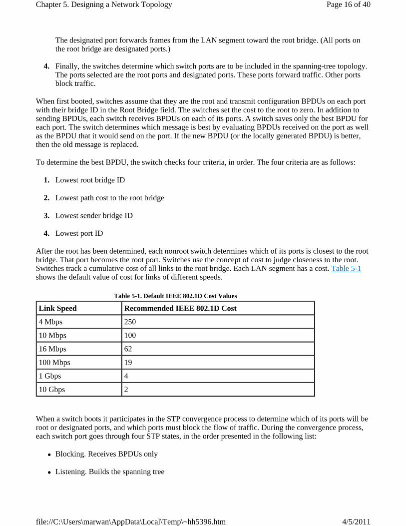
After the root has been determined, each nonroot switch determines which of its ports is closest to the root bridge. That port becomes the root port. Switches use the concept of cost to judge closeness to the root. Switches track a cumulative cost of all links to the root bridge. Each LAN segment has a cost. Table 5-1 shows the default value of cost for links of different speeds.
When a switch boots it participates in the STP convergence process to determine which of its ports will be root or designated ports, and which ports must block the flow of traffic. During the convergence process, each switch port goes through four STP states, in the order presented in the following list:
Blocking. Receives BPDUs only
Listening. Builds the spanning tree
Table 5-1. Default IEEE 802.1D Cost Values
Link Speed Recommended IEEE 802.1D Cost
4 Mbps 250
10 Mbps 100
16 Mbps 62
100 Mbps 19
1 Gbps 4
10 Gbps 2
Page 16 of 40Chapter 5. Designing a Network Topology
4/5/2011file://C:\Users\marwan\AppData\Local\Temp\~hh5396.htm

Learning. Builds the switching (bridging) table
Forwarding. Sends and receives user data
After initialization, a port that is not shut down or administratively disabled begins in the blocking state, where it listens for BPDUs. The switch port does not learn MAC addresses or send or receive user frames in the blocking state.
A switch port transitions to listening after expiration of a short timer or receipt of a configuration BPDU on this port or another port. While in the listening state, the port still does not send any user data or building the switching table, but it is sending and receiving BPDUs in an effort to build the spanning tree. While in this state, the port might determine that it really isn't a designated or root port and revert to the blocking state.
Ports that remain designated or root ports after 15 seconds (the default Forward Delay timer) progress into the learning state where they start building the switching table. User data is still not being passed, however. Learning lasts for another 15 seconds (the default Forward Delay timer). The learning state reduces the amount of flooding required when data forwarding beings.
If a port is still a designated or root port at the end of the learning state period, the port transitions into the forwarding state. At this point, the port finally starts sending and receiving user data frames. Note that over 30 seconds have elapsed. The exact amount of time depends on how much time elapses before a port transitions from blocking to listening, which depends on the switch's capabilities and configuration.
Selecting the Root Bridge
It is good practice to control which switch becomes the root bridge. The root bridge should be a reliable, high-speed switch in the center of the switched topology. If you let switches elect the root on their own, you have little control over the direction that traffic flows and the amount of frame-forwarding delay in your network. If you aren't careful, a slow bridge can become the root bridge. Also, high-speed ports can accidentally be removed from the spanning tree in deference to low-speed ports that are closer to the root bridge.
The root bridge is the switch with the lowest bridge ID. The bridge ID has two parts, a priority field and the MAC address of the switch. If all priorities are left at their default value, the switch or bridge with the lowest MAC address becomes the root. This could easily be one of Cisco's earliest products, because Cisco had such a low vendor ID. (The vendor ID makes up the first 3 bytes of a MAC address, and Cisco's original vendor ID was 00:00:0C.)
Manual control of the root bridge selection process is critical to maintaining high throughput on switched networks. This can be accomplished by ensuring that a particular switch has the lowest bridge ID. It is not recommended (or even possible on some switches) to change the MAC address portion of a bridge ID. Instead, to control the bridge ID, set the bridge priority. On Cisco switches, you can use the set spantree priority or spantree-template 1 priority commands. You should give a single, high-speed, centrally located switch the lowest priority so that it becomes the root bridge. You should also lower the priority on another high-speed, centrally located switch, so that it becomes the root if the primary root fails. Generally these two switches are distribution layer switches.
High-end Cisco switches also support the set spantree root macro. This macro causes the switch to look at the priority of the acting root bridge. If the priority at the existing root bridge is higher than 8,192, the macro automatically sets the local priority to 8,192. If the existing root bridge has a priority less than 8,192, the macro sets the local priority to one less. To configure a backup root, use the set spantree root
Page 17 of 40Chapter 5. Designing a Network Topology
4/5/2011file://C:\Users\marwan\AppData\Local\Temp\~hh5396.htm

secondary macro.
Root Guard
Cisco also supports a feature called Root Guard that protects your network from a low-speed switch hijacking the job of root bridge. A switch port configured for Root Guard cannot become a root port. Instead the port becomes a designated port for its LAN segment. If there is a better BPDU received on the port, Root Guard disables the port, rather than taking the BPDU into account and restarting election of the root bridge. Root Guard needs to be enabled on all ports on all switches that should not become the root bridge. For more information on this feature, refer to www.cisco.com/warp/public/473/74.html.
The STP Topology Change Process
After the spanning tree has been created, STP still needs to adapt to any physical layer problems or reconfigurations as quickly as possible without introducing any loops. There are many possible failures and reconfigurations. Some of them result in traffic being disrupted for 30 seconds (Forward Delay timer * 2) and some result in traffic being disrupted for 50 seconds (Maximum Age timer + (Forward Delay timer * 2)). The Maximum Age timer controls the maximum length of time that a switch port saves configuration BPDU information. The default value of Maximum Age is 20 seconds.
If the root bridge fails, another switch waits until its Maximum Age timer expires and then starts the process of taking over as the root bridge. If the root bridge doesn't fail, but a path to the root bridge fails, the process is slightly different. If an alternate path exists, a blocking port on a downstream switch transitions to listening, learning, and forwarding after its Maximum Age timer expires. If a root port fails, another port on the switch where the failure occurred may transition directly into the listening and learning states without waiting for the Maximum Age timer to expire.
Although there are situations where entire branches of the spanning tree are not affected, there are also many more situations where many branches are affected and reconvergence takes between 30 and 50 seconds. This amount of time may be longer than upper-layer session timeout values. End stations may need to reconnect to their servers or host applications.
Scaling the Spanning Tree Protocol
STP works best when the switched network is kept relatively small and the switches have sufficient CPU power and RAM to do their jobs effectively. On an oversized network with switches that have too little CPU power, BPDUs may not be sent and received properly, resulting in loops. A switch with insufficient RAM or a software problem could also drop BPDUs. In addition, a congested network could cause problems for the transmission of BPDUs.
STP relies on the timely reception of BPDUs. Cisco has a feature called BPDU Skew Detection that allows a switch to keep track of late-arriving BPDUs and notify the administrator by means of syslog messages. This feature is really more of a workaround than a solution. A better plan is to design a switched network with care.
Based on assumptions about STP timers and the propagation delay for sending BPDUs, it is recommended that a switched network topology not span more than seven switches. In other words, two switches in the network should not be more than seven switch hops away from each other, counting themselves. Part of this restriction comes from the Message Age field that BPDUs carry. When a BPDU is propagated from the root bridge toward the leaves of the tree, the Message Age field is incremented each time it goes though a switch. Eventually, when the Message Age goes beyond the Maximum Age, the BPDU is discarded. Typically, this occurs if the root is too far away from some switches in the network. The
Page 18 of 40Chapter 5. Designing a Network Topology
4/5/2011file://C:\Users\marwan\AppData\Local\Temp\~hh5396.htm

problem causes STP to reconverge much more frequently than it should.
Although some STP timers can be changed, a better approach is to plan the campus network design carefully so that routers and routing protocols are introduced to limit the topology of the switched LAN. Routers have advantages compared to switches in their ability to implement security policies, load sharing, and QoS features. Also, routing protocols tend to converge much more quickly than STP. Nevertheless, both the IEEE and vendors continue to improve the performance of STP. One such improvement is the IEEE 802.1w Rapid Spanning Tree Protocol (RSTP), covered in the next section.
Rapid Reconfiguration of the Spanning Tree
IEEE 802.1w, "Rapid Reconfiguration of Spanning Tree," supplements the IEEE 802.1D 1998 standard and defines the changes necessary in switches to provide rapid convergence of the spanning tree. The goal of the 802.1w committee was to standardize an improved mode of switch operation that reduces the time STP takes to reconfigure and restore service after link failures, while retaining the plug-and-play benefits of STP.
RSTP provides rapid convergence of the spanning tree by assigning port roles and by determining the active topology. RSTP builds upon STP to select the switch with the highest switch priority as the root bridge and then assigns port roles (root, designated, alternate, backup, and disabled) to individual ports. These roles assist in rapid convergence, which can be extremely fast (within a second) due to better knowledge of the topology.
Virtual LANs
A campus network should be designed using small bandwidth and small broadcast domains. A bandwidth domain is a set of devices that share bandwidth and compete for access to the bandwidth. A traditional bus topology or hub-based Ethernet, for example, is a single bandwidth domain. A switch divides up bandwidth domains and is often used to connect each device so that the network consists of many, extremely small bandwidth domains. With switches, as opposed to hubs, the bandwidth domain consists of the switch port and the device that connects it. If full-duplex transmission mode is used, a bandwidth domain becomes even smaller and consists of just the port or the device.
A broadcast domain is a set of devices that can all hear each other's broadcast frames. A broadcast frame is a frame that is sent to the MAC address FF:FF:FF:FF:FF:FF. By default, switches do not divide broadcast domains. According to Cisco, the building access module of the Enterprise Composite Network Model should use switches and provide broadcast control, however. To accomplish this, virtual LANs are necessary.
A virtual LAN (VLAN) is an emulation of a standard LAN that allows data transfer to take place without the traditional physical restraints placed on a network. A VLAN is a set of LAN devices that belong to an administrative group. Group membership is based on configuration parameters and administrative policies rather than physical location. Members of a VLAN communicate with each other as if they were on the same wire or hub, when in fact they may be located on different physical LAN segments. Members of a VLAN communicate with members in a different VLAN as if they were on different LAN segments, even when they are located in the same switch. Because VLANs are based on logical instead of physical connections, they are extremely flexible.
In the early days of VLANs in the mid-1990s, there was a lot of talk about using VLANs to group users working on a project together, even though they weren't physically located together. With VLANs, the physical location of a user doesn't matter. A network administrator can assign a user to a VLAN regardless of the user's location. In theory, VLAN assignment can be based on applications, protocols, performance
Page 19 of 40Chapter 5. Designing a Network Topology
4/5/2011file://C:\Users\marwan\AppData\Local\Temp\~hh5396.htm

requirements, security requirements, traffic-loading characteristics, or other factors.
There was also a lot of talk about VLANs simplifying moves, adds, and changes in a campus network. The theory was that with VLANs, network administrators can stay seated in their offices or in the wiring closet when an end user moves into a new office or cubicle. If a user in the marketing department, for example, moves to a new office that is physically located among engineers, the marketing person might not have the skills to configure IP addressing for compatibility with the new location. Asking the engineers for help might not work because engineers don't like marketers, and asking the network administrator to come to the office and make the change might take a long time because administrators are so busy. Instead, the network administrator can configure the switch port for the moved device to be part of the marketing VLAN. Additional changes may be necessary to make sure the other switches learn that the marketing VLAN has expanded into a new area. However, no change is required on the marketer's computer.
In modern networks, VLANs aren't often used this way. Manually configuring IP addresses isn't common since DHCP has become so popular. Also, when a VLAN is dispersed across many physical networks, traffic must flow to each of those networks, which affects the performance of the networks and adds to the capacity requirements of links that connect VLANs. Networks with VLANs that migrate all over the campus topology are hard to manage and optimize.
In modern networks, instead of allowing for the spread of a logical LAN or administrative group across many physical LANs, a VLAN has become a method to subdivide physical switch-based LANs into many logical LANs. VLANs allow a large, flat, switch-based network to be divided into separate broadcast domains. Instead of flooding all broadcasts out every port, a VLAN-enabled switch floods a broadcast out only the ports that are part of the same VLAN as the sending station.
When switches first became popular in the mid-1990s, many companies implemented large switched campus networks with few routers. The goals were to keep costs down by using switches instead of routers, and to provide good performance because presumably switches were faster than routers. Without the router capability of containing broadcast traffic, however, the companies needed VLANs. VLANs allow the large flat network to be divided into broadcast domains. A router (or a routing module within a switch) is still needed for inter-VLAN communication.
In IP-based campus networks, a VLAN is usually its own IP subnet, due to the way the Address Resolution Protocol (ARP) works. When an IP host in a subnet needs to reach another host in the same subnet, it sends an ARP message to determine the Media Access Control (MAC) address of the host it is trying to reach. The ARP message is sent as a broadcast. All devices that find each other this way need to be in the same VLAN. Thus, in an IP network, VLANs are implemented as separate IP subnets. A router (or a routing module within a switch) provides intersubnet communication just as it would for a set of interconnected real (not virtual) LANs.
Fundamental VLAN Designs
To understand VLANs, it helps to think about real (nonvirtual) LANs first. Imagine two switches that are not connected to each other in any way. Switch A connects stations in Network A and Switch B connects stations in Network B, as shown in Figure 5-8.
Figure 5-8. Two Switches with Stations Attached
Page 20 of 40Chapter 5. Designing a Network Topology
4/5/2011file://C:\Users\marwan\AppData\Local\Temp\~hh5396.htm

When Station A1 in Figure 5-8 sends a broadcast, Station A2 and Station A3 receive the broadcast, but none of the stations in Network B receive the broadcast, because the two switches are not connected. This same configuration can be implemented through configuration options in a single switch, with the result looking like Figure 5-9.
Figure 5-9. A Single Switch with Stations from Network A and Network B Attached
Through the configuration of the switch there are now two virtual LANs implemented in a single switch, instead of two separate physical LANs. This is the beauty of VLANs. The broadcast, multicast, and unknown-destination traffic originating with any member of VLAN A is forwarded to all other members of VLAN A, and not to a member of VLAN B. VLAN A has the same properties as a physically separate LAN bounded by routers. The protocol behavior in Figure 5-8 is exactly the same as the protocol behavior in Figure 5-9.
VLANs can span multiple switches. In Figure 5-10, both switches contain stations that are members of VLAN A and VLAN B. This design introduces a new problem, the solution to which is specified in the IEEE 802.1Q standard and the Cisco proprietary Inter-Switch Link (ISL) protocol. The problem has to do with the forwarding of broadcast, multicast, or unknown-destination frames from a member of a VLAN on one switch to the members of the same VLAN on the other switch.
Figure 5-10. VLAN A and VLAN B Span Two Switches
[View full size image]
Page 21 of 40Chapter 5. Designing a Network Topology
4/5/2011file://C:\Users\marwan\AppData\Local\Temp\~hh5396.htm

In Figure 5-10, all frames going from Switch A to Switch B take the same interconnection path. The 802.1Q standard and the Cisco ISL protocol define a method for Switch B to recognize whether an incoming frame belongs to VLAN A or to VLAN B. As a frame leaves Switch A, a special header is added to the frame, called the VLAN tag. The VLAN tag contains a VLAN identifier (ID) that specifies to which VLAN the frame belongs.
Because both switches have been configured to recognize VLAN A and VLAN B, they can exchange frames across the interconnection link, and the recipient switch can determine the VLAN into which those frames should be sent by examining the VLAN tag. The link between the two switches is sometimes called a trunk link or simply a trunk.
Trunk links allow the network designer to stitch together VLANs that span multiple switches. A major design consideration is determining the scope of each VLAN and how many switches it should span. As mentioned earlier, most designers try to keep the scope small. Each VLAN is a broadcast domain, and per recommendations specified in the previous chapter (see Table 4-8), a single broadcast domain should be limited to a few hundred workstations (or other devices, such as IP phones).
Another major design consideration is the capacity of trunk links. Using methods discussed in Chapter 4, you should study network traffic to determine if Fast Ethernet, Gigabit Ethernet, or multiples of Fast or Gigabit Ethernet will be required for trunk links. Although Cisco supports 10-Mbps Ethernet trunks on some equipment, 10 Mbps is usually sufficient only for trunks that support very small networks or for lab networks used for learning and testing purposes.
Wireless LANs
As discussed in Part I of this book, user mobility has become an important goal for many enterprises. In a campus network design, one or more wireless LANs (WLANs) can meet this goal by offering intranet and Internet access in open areas on the campus and in high-density areas such as auditoriums, conference rooms, and cafeterias. WLAN technology also enables deployment of LANs in offices or other parts of buildings where it may not be cost-effective or practical to install cabling.
A WLAN consists of access points that communicate using radio frequency (RF) with wireless clients. The area that a single access point can cover is often called a wireless cell. Designing a WLAN topology requires a designer to determine the coverage area of each wireless cell and to decide how many cells will be required to meet total coverage needs. Factors that affect the coverage of a single access point include data rate, power level, antenna choice, and antenna positioning. Architectural characteristics of the wireless site also affect coverage, as described in the "Checking a Site for a Wireless Installation" section in Chapter 3, "Characterizing the Existing Internetwork."
Page 22 of 40Chapter 5. Designing a Network Topology
4/5/2011file://C:\Users\marwan\AppData\Local\Temp\~hh5396.htm

Positioning an Access Point for Maximum Coverage
Most access points use an isotropic antenna, which means that the signal strength is theoretically the same when measured along axes in all directions. If you suspend an access point in space, the coverage should resemble that of a three-dimensional sphere with the access point at its center. In reality, the limitations of antenna design usually result in less-uniform coverage, however. The most common type of access point antenna is omnidirectional, which isn't really "omni" or "iso." Instead of a sphere, the coverage looks more like a donut or tire inner tube.
An omnidirectional antenna is usually a 4- to 6-inch transmitting element, often attached to a rotating or positionable pivot. The signal propagating from an omnidirectional antenna is strongest in a direction perpendicular to the antenna shaft and weakest in the same direction as the antenna shaft. Remembering this can help you position your antennae for maximum coverage (and help you decide if you may need a directional antenna instead of an omnidirectional antenna).
CAUTION
Think about the meaning of omni in omnidirectional. Placing an access point near an exterior wall means that some of the signal will probably radiate strongly outside the building where an unauthorized user sitting in the parking lot can easily receive it. Also, keep in mind that an access point in one room can propagate through a wall to potentially interfere with an access point in the next room. Walls attenuate (decrease) the strength of the signal, but they don't block it completely.
Access points can be mounted in a horizontal or a vertical position. It's important to make sure that an omnidirectional antenna points straight up. In addition to the access point antenna, also consider the antenna in receiving stations, usually notebook computers. Every wireless NIC and computer is different. Some laptops have long antennas that extend from the card up through the back of the laptop, behind the screen. Other computers may not have a built-in antenna and must rely on a smaller antenna in the NIC. You should test your WLAN design with a variety of computers and other devices that the actual users will be using.
For a given data rate, you can alter the power level or choose a different antenna to change the coverage area and coverage shape. A large cell size may result in too many clients sharing the available bandwidth. (IEEE 802.11 WLANs are shared networks, with all devices in the same bandwidth domain.) By reducing the access point power or antenna gain, you can reduce the cell size and share the bandwidth with fewer clients. This will result in more access points for a given coverage area, but will provide better performance for clients.
WLANs and VLANs
You can place multiple access points throughout a facility to give users the ability to roam freely throughout an extended area while maintaining uninterrupted access to network resources. The easiest method for making sure users can roam is to put all of the users in the same IP subnet and the same VLAN. Otherwise, devices that move from subnet to subnet must acquire a new IP address and can lose packets that might have been transmitted while they were acquiring an address.
Whenever possible, a WLAN should be a separate subnet to simplify addressing while roaming and also to improve management and security. Keeping all wireless clients in their own subnet makes it easier to set up traffic filters to protect wired clients from an attack launched from the WLAN.
Redundant Wireless Access Points
Page 23 of 40Chapter 5. Designing a Network Topology
4/5/2011file://C:\Users\marwan\AppData\Local\Temp\~hh5396.htm

In both wired and wireless campus LAN architectures, redundancy is usually desirable to ensure high availability. For campus networks with WLANs that are mission critical, Cisco has a feature called access-point hot standby that supports two access points being configured to use the same channel in a single coverage area. Only one of the access points is active. The standby access point passively monitors the network and the primary access point. If the primary access point fails, the secondary access point takes over to provide coverage.
NOTE
Don't confuse access-point hot standby with Cisco's Hot Standby Router Protocol (HSRP), which is covered in the "Workstation-to-Router Redundancy" section. Access-point hot standby addresses Layer 2 redundancy, whereas HSRP addresses Layer 3 redundancy.
You should place the standby access point near the access point it will monitor and give it the same configuration (except for a different IP address). The standby access point associates with the monitored access point as a client and queries the monitored access point regularly through both the Ethernet interface and the RF interface. If the monitored access point fails to respond, the standby access point becomes active, signals the primary access point radio to become quiescent, and takes the monitored access point's place in the network.
As soon as the primary access point failure is detected, user intervention is required. The user should return the backup access point to standby mode. Failure to reset the standby access point results in both the primary and standby access points operating concurrently on the same channel when the primary access point comes back online.
Redundancy and Load Sharing in Wired LANs
In wired campus networks, it is common practice to design redundant links between LAN switches. Most LAN switches implement the IEEE 802.1D spanning-tree algorithm to avoid network loops. The 802.1D standard is a good solution for redundancy, but not for load sharing, because only one path is active. Some switch vendors, including Cisco, let you have one spanning tree per VLAN, which can be used to implement redundancy. A switch can act as the root bridge for one VLAN and as a backup for the root bridge for another VLAN.
Cisco's Per VLAN Spanning Tree+ (PVST+) builds a separate logical tree topology for each VLAN. PVST+ allows load sharing by having different forwarding paths per VLAN. PVST+ is less scalable than the classic 802.1D method, where there is just one root and tree, because CPU time is required to process BPDUs for each VLAN. Cisco overcame this limitation with the Multi-Instance Spanning-Tree Protocol (MISTP), which allows a set of VLANs to be grouped into a single spanning tree.
IEEE has also enhanced the original spanning-tree algorithm with its Multiple Spanning Trees (MST) standard, which is documented in IEEE 802.1s. The Multiple Spanning Tree Protocol (MSTP) uses RSTP for rapid convergence but improves RSTP scalability by aggregating a set of VLAN-based spanning trees into distinct instances, and by running only one (rapid) spanning-tree algorithm per instance. This architecture provides multiple forwarding paths for data traffic, enables load sharing, and reduces the number of spanning trees required to support a large number of VLANs.
If you use VLANs in a campus network design with switches that support 802.1s, PVST+ or MISTP, redundant links can offer load sharing in addition to fault tolerance. Figure 5-11 shows a redundant campus LAN design that uses the spanning-tree algorithm and VLANs.
Page 24 of 40Chapter 5. Designing a Network Topology
4/5/2011file://C:\Users\marwan\AppData\Local\Temp\~hh5396.htm

Figure 5-11. A Campus Hierarchical Redundant Topology
The design in Figure 5-11 takes advantage of the concept of one spanning tree per VLAN. Switch A acts as the root bridge for VLANs 2, 4, and 6. (Switch B can become the root bridge for those VLANs if Switch A fails.) Switch B acts as the root bridge for VLANs 3, 5, and 7. (Switch A can become the root bridge for those VLANs if Switch B fails.) The result is that both links from an access layer switch carry traffic, and failover to a new root bridge happens automatically if one of the distribution layer switches fails. Both load sharing and fault tolerance are achieved.
The design in Figure 5-11 can scale to a very large campus network. The design has been tested on a network that has 8000 users, 80 access layer switches, 14 distribution layer switches, and 4 core campus routers (not counting the routers going to the WAN).
Server Redundancy
This section covers guidelines for server redundancy in a campus network design. File, web, Dynamic Host Configuration Protocol (DHCP), name, and database servers are all candidates for redundancy in a campus design, depending on a customer's requirements. In a network that supports Voice over IP (VoIP), the servers that provide the mapping between a phone number and an IP address and handle call processing should be provisioned in a redundant fashion. Cisco CallManager software, for example, supports a redundancy group where servers are assigned the role of primary, secondary, or tertiary server.
Once a LAN has been migrated to using DHCP servers for the IP addressing of end systems, the DHCP servers become critical. Because of this, you should recommend redundant DHCP servers. The servers should hold redundant (mirrored) copies of the DHCP database of IP configuration information.
DHCP servers can be placed at either the access or distribution layer. In small networks, redundant DHCP servers are often placed at the distribution layer. For larger networks, redundant DHCP servers are usually placed in the access layer. This avoids excessive traffic between the access and distribution layers, and
Page 25 of 40Chapter 5. Designing a Network Topology
4/5/2011file://C:\Users\marwan\AppData\Local\Temp\~hh5396.htm

allows each DHCP server to serve a smaller percentage of the user population.
In large campus networks, the DHCP server is often placed on a different network segment than the end systems that use it. If the server is on the other side of a router, the router can be configured to forward DHCP broadcasts from end systems. The router forwards the broadcasts to a server address configured via the ip helper address command on a Cisco router. The router inserts the address of the interface that received the request into the giaddr field of the DHCP request. The server uses the giaddr field to determine from which pool of addresses to choose an address.
Name servers are less critical than DHCP servers because users can reach services by address instead of name if the name server fails; because many users do not realize this, however, it is a good idea to plan for redundant name servers. Name servers implement the Internet Domain Name System (DNS), the Windows Internet Naming Service (WINS), and the NetBIOS Name Service (NBNS). Name servers can be placed at the access or distribution layer.
In any application where the cost of downtime for file servers is a major concern, mirrored file servers should be recommended. For example, in a brokerage firm where traders access data to buy and sell stocks, the data can be replicated on two or more mirrored file servers. Mirrored file servers hold identical data. Updates to the data are synchronized across the servers. The servers should be on different networks and power supplies to maximize availability.
If complete server redundancy is not feasible due to cost considerations, mirroring or duplexing of the file server hard drives is a good idea. (Duplexing is the same as mirroring with the additional feature that the two hard drives are controlled by different disk controllers.) Implementing a storage-area network (SAN) is another option. SANs are quickly becoming a popular solution for organizations seeking highly reliable, uninterrupted access to large amounts of stored information. SANs are not covered in this book because of their specialized nature, but to learn more about SANs, see the Cisco white paper titled "The Strategic and Financial Justification of Storage Area Networks." It is available at http://www.cisco.com/en/US/products/hw/ps4159/ps4358/products_white_paper09186a00800c464f.shtml.
Redundancy has both availability and performance advantages. With mirrored file servers, it is possible to share the workload between servers. Using a content delivery network (CDN) and content services devices, users can be directed to one of many mirrored servers that all hold the same data.
Redundancy can also be achieved by adding some sophistication to DNS. When a client requests access to a resource by its DNS name, a DNS server can return multiple host addresses in its response. Whether this will provide good redundancy depends on the host software. Some implementations try additional addresses if the first one doesn't respond.
Another possibility is a feature called DNS round robin, where the server has a list of addresses through which it cycles. The server gives out a different address with each request, going through its list of addresses. When it gets to the end of the list, it cycles back to the beginning of the list. Due to DNS caching, where clients and other DNS servers remember a previous name-to-address mapping, DNS round robin isn't perfect, but it can be quite simple to implement and configure on a typical DNS server.
Redundancy and load balancing with DNS can also work with multiple DNS servers. Assuming that clients access different DNS servers, one server can respond with one address, while other servers respond with different addresses. Once again, DNS caching can limit the effectiveness of this method.
NOTE
Page 26 of 40Chapter 5. Designing a Network Topology
4/5/2011file://C:\Users\marwan\AppData\Local\Temp\~hh5396.htm

There is one caveat to keep in mind with mirrored file, DHCP, web, and other types of servers. Mirrored servers offer redundancy for the hardware, cabling, LAN connection, and power supply, but they do not offer software or data redundancy. Because mirrored servers hold replicated data, if the problem is in the data or the software's ability to access the data, then all the mirrored servers are affected.
Workstation-to-Router Redundancy
Workstations in a campus network must have access to a router to reach remote services. Because workstation-to-router communication is critical in most designs, you should consider implementing redundancy for this function.
A workstation has many possible ways to discover a router on its network, depending on the protocol it is running and also the implementation of the protocol. The next few sections describe methods for workstations to learn about routers, and redundancy features that guarantee a workstation can reach a router.
Although AppleTalk and Novell NetWare are being phased out of many networks, it's still useful to learn how the developers of those protocols solved the problem of workstation-to-router communication. This section starts with a discussion of those protocols and then moves on to IP workstation-to-router communication.
AppleTalk Workstation-to-Router Communication
An AppleTalk workstation remembers the address of the router that sent the most recent RTMP packet. Although the workstation does not participate in the routing protocol process, it does hear RTMP broadcast packets and copy into memory the address of the router that sent the broadcast. As long as there is at least one router on the workstation's network, the workstation can reach remote devices. If there are multiple routers on a workstation's network, the workstation very quickly learns a new way to reach remote stations when a router fails, because AppleTalk routers send RTMP packets every 10 seconds.
To minimize memory and processing requirements on an AppleTalk device, the AppleTalk specification states that a workstation remembers the address of only one router (the router that most recently sent an RTMP packet). Recall that AppleTalk was designed to run on 128-KB RAM Macintoshes and was optimized for simplicity. The result is that a workstation does not always use the most expedient method to reach a remote station. The workstation can select a path that includes an extra hop. Figure 5-12 shows the extra-hop problem.
Figure 5-12. The Workstation-to-Router Extra-Hop Problem
Page 27 of 40Chapter 5. Designing a Network Topology
4/5/2011file://C:\Users\marwan\AppData\Local\Temp\~hh5396.htm

In 1989, Apple Computer, Inc., introduced AppleTalk Phase 2, which includes the best router forwarding algorithm. With the best router forwarding algorithm, a workstation can maintain a cache of the best routers to use to reach remote networks. If a destination network is in the cache, the workstation can avoid the extra-hop problem.
Novell NetWare Workstation-to-Router Communication
Novell NetWare workstation-to-router communication is very simple. When a NetWare workstation determines that a packet is destined for a remote destination, the workstation broadcasts a find-network-number request to find a route to the destination. Routers on the workstation's network respond to the request. The workstation uses the first router that responds to send packets to the destination. If the workstation determines that it can no longer reach the destination, it automatically sends the find-network-number request again. If a router fails, as long as there is another router on the workstation's network, the workstation discovers the other router and the session continues.
IP Workstation-to-Router Communication
IP implementations vary in how they implement workstation-to-router communication. Some IP workstations send an Address Resolution Protocol (ARP) frame to find a remote station. A router running proxy ARP can respond to the ARP request with the router's data link layer address. Cisco routers run proxy ARP by default.
The advantage of depending on proxy ARP to reach remote stations is that a workstation doesn't have to be configured with the address of a router. However, because proxy ARP has never been standardized, most network administrators don't depend on it. Also, many security experts recommend turning it off because it makes it easier for an attacker to reach another network. Instead, IP workstations are given the address of a default router. This can be manually configured or supplied by DHCP. A default router is the address of a router on the local segment that a workstation uses to reach remote services. (The default router is usually called the default gateway for historical reasons.)
As was the case with AppleTalk, sometimes using the default gateway is not the most expedient path to the destination. (See Figure 5-12.) To get around the extra-hop problem and to add redundancy, some workstation IP implementations allow a network administrator to add static routes to a configuration file or to configure the workstation to run a routing protocol.
NOTE
In UNIX environments, workstations often run the RIP daemon to learn about routes. It is best if they run the RIP daemon in passive rather than active mode. In active mode, a workstation sends a RIP broadcast frame every 30 seconds. When many UNIX workstations run RIP in active mode, the amount of broadcast traffic can degrade network performance. In addition, there are security risks in allowing uncontrolled stations to run a routing protocol in active mode.
Another alternative for IP workstation-to-router communication is the Router Discovery Protocol (RDP). Request For Comments (RFC) 1256 specifies the RDP extension to the Internet Control Message Protocol (ICMP). With RDP, each router periodically multicasts an ICMP router advertisement packet from each of its interfaces, announcing the IP address of that interface. Workstations discover the addresses of their local routers simply by listening for advertisements, in a similar fashion to the method AppleTalk workstations use to discover the address of a router. (The default advertising rate for RDP is once every 7 to 10 minutes, though, which is quite different than AppleTalk, which is once every 10 seconds).
Page 28 of 40Chapter 5. Designing a Network Topology
4/5/2011file://C:\Users\marwan\AppData\Local\Temp\~hh5396.htm

When a workstation starts up, it can multicast an ICMP router solicitation packet to ask for immediate advertisements, rather than wait for the next periodic advertisement to arrive. RDP does not attempt to solve the extra-hop problem. Although most routers support RDP, few workstation IP implementations support it, so RDP is not widely used.
One reason that RDP has not become popular is that DHCP includes an option for a DHCP server to return the address of a default gateway to a client. As specified in RFC 2131, a server's response to a DHCP client's request for an IP address can include an options field in which the server can place one or more default gateway addresses. A preference level can be used to specify which default gateway is the best option. The server can also include a list of static routes in the options field.
These days most IP workstations are configured with the address of a default gateway. The configuration can be done at each workstation or at a DHCP server that supports many workstations, which is the more common method. Running routing protocols or router discovery protocols at workstations has proven to be a poor alternative because of traffic and processing overhead, security issues, and the lack of implementations for many platforms.
The problem with a default gateway configuration is that it creates a single point of failure, particularly because many implementations keep track of only one default gateway. Loss of the default gateway results in workstations losing connections to remote sites and being unable to establish new connections.
Hot Standby Router Protocol
The Cisco Hot Standby Router Protocol (HSRP) provides a way for an IP workstation to keep communicating on an internetwork even if its default gateway becomes unavailable. In RFC 2338, the IETF standardized a similar protocol called the Virtual Router Redundancy Protocol (VRRP). Routers in the core, distribution, or access layer can run HSRP or VRRP. The campus design shown in Figure 5-11 features HSRP at the core layer.
HSRP works by creating a virtual router, also called a phantom router, as shown in Figure 5-13. The virtual router has its own IP and MAC addresses. Each workstation is configured to use the virtual router as its default gateway. When a workstation broadcasts an ARP frame to find its default gateway, the active HSRP router responds with the virtual router's MAC address. If the active router goes offline, a standby router takes over as active router, continuing the delivery of the workstation's packets. The change is transparent to the workstation.
Figure 5-13. The Hot Standby Router Protocol (HSRP)
Page 29 of 40Chapter 5. Designing a Network Topology
4/5/2011file://C:\Users\marwan\AppData\Local\Temp\~hh5396.htm
HSRP routers on a LAN communicate among themselves to designate an active and standby router. The active router sends periodic Hello messages. The other HSRP routers listen for the Hello messages. If the active router fails, causing the other HSRP routers to stop receiving Hello messages, the standby router takes over and becomes the active router. Because the new active router assumes both the IP and MAC addresses of the phantom, workstations see no change. They continue to send packets to the virtual router's MAC address, and the new active router delivers those packets. The Hello timer should be configured to be short enough so that workstation applications and protocols do not drop connections before the standby router becomes active.
HSRP also works for proxy ARP. When an active HSRP router receives an ARP request for a station that is not on the local network, the router replies with the virtual router's MAC address. If the router becomes unavailable, the new active router can still deliver the traffic.
Cisco also has a useful enhancement to HSRP, called standby tracking, which monitors one or more WAN interfaces on a router that has HSRP enabled on the LAN interfaces. If the software senses a problem with the WAN circuit connected to one of the WAN interfaces that it is tracking, it fails over to an active WAN interface on a standby router. The default gateway, for which HSRP provides redundancy, is the user's method of getting outside the LAN and is often connected to a WAN interface that provides access to the rest of the intranet or the Internet, so the standby tracking feature is extremely useful.
Cisco also supports an HSRP-enabled router preserving Network Address Translation (NAT) and IPSec state information. WAN edge devices can maintain NAT translations and IPSec tunnels, used in VPNs usually, when HSRP switches to a different router.
Gateway Load Balancing Protocol
To achieve load sharing along with redundancy, Cisco also has a newer protocol called the Gateway Load Balancing Protocol (GLBP). GLBP is similar, but not identical, to HSRP and VRRP. With HSRP and VRRP, the standby routers in a group are superfluous until the active router fails. These standby routers may have access to bandwidth that is wasted until a problem arises. Although multiple virtual router groups can be configured for the same set of routers, which is less wasteful, the hosts must be configured for different default gateways, which results in an extra administrative burden. GLBP provides load balancing over multiple routers using a single virtual IP address and multiple virtual MAC addresses. Each host is configured with the same virtual IP address, and all routers in the virtual router group participate in forwarding packets.
Members of a GLBP group elect one router to be the active virtual gateway (AVG) for that group. Other group members provide backup for the AVG in the event that the AVG becomes unavailable. The AVG assigns a virtual MAC address to each member of the GLBP group. Each gateway assumes responsibility for forwarding packets sent to the virtual MAC address assigned to it by the AVG. These gateways are known as active virtual forwarders (AVFs) for their virtual MAC address. The AVG is responsible for answering ARP requests for the virtual IP address. Load sharing is achieved by the AVG replying to the ARP requests with different virtual MAC addresses.
< Day Day Up > < Day Day Up >
Designing the Enterprise Edge Topology
Depending on a customer's goals for availability, performance, and affordability, enterprise edge network design should feature redundant WAN segments in the intranet, and multiple paths to extranets and the
Page 30 of 40Chapter 5. Designing a Network Topology
4/5/2011file://C:\Users\marwan\AppData\Local\Temp\~hh5396.htm

Internet. VPNs can also be used to connect private enterprise sites via a service provider's public WAN or the Internet. This section covers enterprise edge topologies that include redundant WAN segments, multihomed connections to the Internet, and VPNs. The section also includes a few comments about the service provider edge.
Redundant WAN Segments
Because WAN links can be critical pieces of an enterprise internetwork, redundant (backup) WAN links are often included in an enterprise edge network topology. A WAN network can be designed as a full mesh or a partial mesh. A full-mesh topology provides complete redundancy. It also provides good performance because there is just a single-link delay between any two sites. However, as already discussed in this chapter, a full mesh is costly to implement, maintain, upgrade, and troubleshoot. A hierarchical partial-mesh topology, as shown previously in Figure 5-4, is usually sufficient.
Circuit Diversity
When provisioning backup WAN links, you should learn as much as possible about the actual physical circuit routing. Different carriers sometimes use the same facilities, meaning that your backup path is susceptible to the same failures as your primary path. You should do some investigative work to ensure that your backup really is a backup. Network engineers use the term circuit diversity to refer to the optimum situation of circuits using different paths.
Because carriers lease capacity to each other and use third-party companies that provide capacity to multiple carriers, it is getting harder to guarantee circuit diversity. Also, carriers often merge with each other and mingle their circuits after the merge. As carriers increasingly use automated techniques for physical circuit rerouting, it becomes even more difficult to plan diversity because the rerouting is dynamic.
Nonetheless, you should work with the providers of your WAN links to gain an understanding of the level of circuit diversity in your network design. Carriers are usually willing to work with customers to provide information about physical circuit routing. (Be aware, however, that carriers sometimes provide inaccurate information, based on databases that are not kept current.) Try to write circuit-diversity commitments into contracts with your providers.
When analyzing circuit diversity, be sure to analyze your local cabling in addition to your carrier's services. Perhaps you have designed an ISDN link to back up a Frame Relay link. Do both of these links use the same cabling to get to the demarcation point in your building network? What cabling do the links use to get to your carrier? The cabling that goes from your building to the carrier is often the weakest link in a network. It can be affected by construction, flooding, ice storms, trucks hitting telephone poles, and other factors.
Multihoming the Internet Connection
The generic meaning of multihoming is to "provide more than one connection for a system to access and offer network services." The term multihoming is used in many specific ways also. A server, for example, is said to be multihomed if it has more than one network layer address. Content delivery networks can multihome application layer data and services.
The term multihoming is increasingly being used to refer to the practice of providing an enterprise network more than one entry into the Internet. Redundant entries into the Internet provide fault tolerance for applications that require Internet access. An enterprise network can be multihomed to the Internet in many different ways, depending on a customer's goals. Figure 5-14 and Table 5-2 describe some methods for
Page 31 of 40Chapter 5. Designing a Network Topology
4/5/2011file://C:\Users\marwan\AppData\Local\Temp\~hh5396.htm

multihoming the Internet connection.
Figure 5-14. Options for Multihoming the Internet Connection
Table 5-2. Description of Options for Multihoming the Internet Connection
Number of Routers at the Enterprise
Number of Connections to the Internet
Number of ISPs Advantages Disadvantages
Option A
1 2 1 WAN backup; low cost; working with one ISP can be easier than working with multiple ISPs.
No ISP redundancy; router is a single point of failure; this solution assumes the ISP has two access points near the enterprise.
Option B
1 2 2 WAN backup; low cost; ISP
Router is a single point of failure; it
Page 32 of 40Chapter 5. Designing a Network Topology
4/5/2011file://C:\Users\marwan\AppData\Local\Temp\~hh5396.htm

In the case of Options C and D, the goal might be to improve network performance by allowing European enterprise sites to access the Internet using the Paris router and North American sites to use the New York router. This can be accomplished by correctly configuring a default gateway on end stations and a default route on enterprise routers in Europe and North America. (A default route specifies where a packet should go if there is no explicit entry for the destination network in a router's routing table. Default route is also sometimes called the gateway of last resort.)
Your customer might have more complex goals than the simple goal in the previous paragraph. Perhaps your customer wants to guarantee that European enterprise sites access North American Internet sites via the New York router. A parallel goal is that North American enterprise sites access European Internet sites via the Paris router. This could be a reasonable goal when a constant, low latency is required for an application. The latency is more predictable if the first part of the path is across the enterprise intranet instead of the Internet. This goal is harder to meet than the first goal, however. It requires that the enterprise routers understand routes from the ISP and set preferences on those routes.
A related goal is to use the "best route" across the Internet to the sites that the enterprise users most rely on. Unless an enterprise contracts (and pays) for end-to-end managed quality of service (QoS), this goal cannot be met. The routing protocol used on the Internet, BGP, doesn't offer route optimality. Its only purpose is to provide reachability and stability in the global routing system. Intermediate providers with whom an enterprise has no business relationship don't care if the enterprise's traffic follows optimal routes, nor do they have any incentive to do so.
Another more complex goal is to guarantee that incoming traffic from the Internet destined for European enterprise sites uses the Paris router and incoming traffic for North American enterprise sites uses the New York router. This goal requires the enterprise routers to advertise to the Internet routes to enterprise sites. The routes must include metrics so that routers on the Internet know the preferred path to sites on the enterprise intranet.
redundancy. can be difficult to deal with policies and procedures of two different ISPs.
Option C
2 2 1 WAN backup; especially good for geographically dispersed company; medium cost; working with one ISP can be easier than working with multiple ISPs.
No ISP redundancy.
Option D
2 2 2 WAN backup; especially good for geographically dispersed company; ISP redundancy.
High cost; it can be difficult to deal with policies and procedures of two different ISPs.
Page 33 of 40Chapter 5. Designing a Network Topology
4/5/2011file://C:\Users\marwan\AppData\Local\Temp\~hh5396.htm

One other caveat when an enterprise network is multihomed is the potential to become a transit networkthat provides interconnections for other networks. Looking at the pictures in Figure 5-14, consider that the enterprise router learns routes from the ISP. If the enterprise router advertises these learned routes, then it risks allowing the enterprise network to become a transit network and being loaded by unintended external traffic. When an enterprise network becomes a transit network, routers on the Internet learn that they can reach other routers on the Internet via the enterprise network. To avoid this situation, enterprise routers should advertise only their own routes. (Alternatively they cannot run a routing protocol and depend on default and static routing.)
In general, multihoming the Internet connection can be challenging if a customer's goals are complex. Encourage your customers to simplify their goals to ensure ease of implementation, scalability, availability, and affordability. If the main goal is high availability, don't assume that this means more redundancy is required. According to Howard Berkowitz in his book WAN Survival Guide, "Uncontrolled increases in redundancy lead to uncontrolled increases in complexity, and may actually decrease availability." See Berkowitz's book and other books listed in Appendix B, "References and Recommended Reading," for more information on maximizing the availability of Internet access.
Virtual Private Networking
Virtual private networks (VPNs) use advanced encryption and tunneling to permit organizations to establish secure, end-to-end, private network connections over a third-party network. The third-party network can be a private service provider network or the public Internet. An organization can connect to the third-party network using a variety of WAN and remote-access technologies, including leased lines, Frame Relay, cable modems, digital subscriber line (DSL), analog modems, ISDN, and so on. Organizations can also use VPNs to connect outside users, such as business partners, customers, resellers, and suppliers. VPNs also support mobile users and telecommuters.
Point-to-point connectivity across the third-party network is typically provided by a tunneling protocol. Tunneling is a technique for encapsulating packets of one protocol inside another protocol. For example, a tunnel can carry IPv4 packets across an internetwork that supports only IPv6. In the context of a VPN, tunneling is used to encapsulate private messages and apply encryption algorithms to the payload.
Tunnels provide a logical, point-to-point connection across a connectionless IP network, enabling application of advanced security features. Encryption is applied to the tunneled connection to scramble data, thus making data legible only to authorized systems. In applications where security and privacy are less of a concern, tunnels can be used without encryption to provide multiprotocol support.
Layer 2 tunneling methods encapsulate at the data link layer of the OSI model. Examples include Point-to-Point Tunneling Protocol (PPTP), Layer 2 Forwarding (L2F), MPLS VPNs, and Layer 2 Tunneling Protocol (L2TP). L2TP is an IETF standard (RFC 2661) that many vendors support for their VPN solutions, including Cisco and Microsoft. The IETF is also developing a new version of L2TP, called L2TPv3. L2TPv3 is emerging as a lightweight yet robust solution for Layer 2 tunneling.
Layer 3 tunneling encapsulates at the network layer. Two examples are IPSec and Cisco's generic routing encapsulation (GRE). If only IP-unicast packets are being tunneled, IPSec is the best choice. GRE is used when multicast, broadcast, and non-IP packets need to be tunneled.
VPN applications for enterprise networks can be divided into two main categories: site to site and remote access. Site-to-site VPNs focus on connecting geographically dispersed offices and are an extension of the classic enterprise WAN. A site-to-site VPN can also add interconnections between multiple organizations, in which case it is sometime called an extranet VPN. Remote-access VPNs focus on remote users and business partners who access the network on an as-needed basis.
Page 34 of 40Chapter 5. Designing a Network Topology
4/5/2011file://C:\Users\marwan\AppData\Local\Temp\~hh5396.htm

Site-to-Site VPNs
Site-to-site VPNs have emerged as a relatively inexpensive way for a company to connect geographically dispersed branch offices and home offices via a service provider or the Internet, as opposed to maintaining an expensive private WAN. The company's private data can be encrypted for routing through the service provider's network or the Internet. Traditionally, businesses relied on private 1.544-Mbps T1 leased lines to link remote offices together. Leased lines are expensive to install and maintain. For many companies, a leased line provides more bandwidth than is needed at too high a price. A site-to-site VPN is a more cost-effective and manageable solution.
When designing the topology of a site-to-site network, you should consider the same needs that you would for a private WAN, including the need for high availability with automatic failover, performance, security, and scalability. The most common topologies for a site-to-site VPN are as follows:
Hub-and-spoke topology
Mesh topology
Hierarchical network topology
The hub-and-spoke topology is used when there is a single regional or headquarters location with many remote offices, and most traffic is between the remote sites and the regional or headquarters location. This design minimizes configuration complexity by having a single IPSec connection or a single GRE tunnel from each remote location back to the regional or headquarters location. This design isn't appropriate when there is a high level of traffic between remote sites or when there is a need for redundancy and automatic failover. An enhancement to the design is to include multiple VPN routers at headquarters to provide better redundancy.
Mesh VPN designs can either be fully meshed, providing any-to-any connectivity, or partially meshed, providing some-to-some connectivity, depending upon customer requirements. The meshed topology is a good design to use when there are a small number of total locations (regional, headquarters, or remote locations), with a large amount of traffic flowing between some (partial mesh) or all (full mesh) of the sites. In a fully meshed design, the loss of a single location only affects traffic to or from that location. All other locations remain unaffected. This design does not scale well when there are numerous sites, due to the large number of IPSec connections or GRE tunnels with IPSec that have to be configured on each device.
A hierarchical VPN topology is a hybrid topology for a large company that has many headquarters and regional offices with a lot of traffic flowing between them, and many remote offices, with little interaction between them. The topology consists of a full- or partial-mesh core, with peripheral sites connecting into the core using a hub-and-spoke design. A hierarchical design is the most complex of the designs in terms of configuration, and may have a combination of IPSec and GRE tunnels.
Remote-Access VPNs
Remote-access VPNs permit on-demand access to an organization's internetwork, via secure, encrypted connections. Mobile or remote users, and branch offices that don't need to always be connected, can access their corporate networks via a third-party network, such as a service provider's network or the Internet. Enterprises use remote-access VPNs to reduce communications expenses by leveraging the local infrastructures of service providers who support dialup, ISDN, cable modem, DSL, or wireless access to the Internet or the provider's private network.
Page 35 of 40Chapter 5. Designing a Network Topology
4/5/2011file://C:\Users\marwan\AppData\Local\Temp\~hh5396.htm

When implementing a remote-access VPN architecture, an important consideration is where to initiate tunneling and encryption. Should the tunnel initiate on the client PC or on a network access server (NAS) operated by the VPN service provider? In a client-initiated model, the encrypted tunnel is established by client software using IPSec, L2TP, or PPTP, thereby making the service provider network solely a means of transport to the corporate network. An advantage of a client-initiated model is that the "last mile" service provider access network used for accessing the provider point of presence (POP) is secured. A disadvantage of the client-initiated model is the need to manage software on client machines.
In a NAS-initiated model, a remote user accesses a service provider's POP, is authenticated by the service provider, and, in turn, initiates a secure tunnel to the corporate network from the POP. With a NAS-initiated architecture, VPN intelligence resides in the service provider network. There is no end-user client software for the organization to maintain, thus eliminating client management issues associated with remote access. The drawbacks, however, are lack of security on the local access network connecting the client to the service provider network and the need to interoperate with servers operated by the provider. Figure 5-15 shows a remote-access VPN topology for a retail company. The company uses both client-initiated and NAS-initiated tunnels.
Figure 5-15. A Remote-Access VPN for a Retail Company
At the headquarters, user VPN connections terminate in the VPN/Remote Access module of the Enterprise Edge area, according to Cisco's Enterprise Composite Network Model. (See Figure 5-7.) Cisco recommends that one or more VPN concentrators reside within this area. A VPN concentrator is a dedicated hardware platform that aggregates a large volume of simultaneous VPN connections. Generally, enterprises place the concentrator between a router that has access to the VPN and a router that forwards traffic into the campus network. The VPN/Remote Access module also includes an authentication, authorization, and accounting (AAA) server and an intrusion detection system (IDS). Refer to Cisco.com for more information about VPNs and the Enterprise Composite Network Model.
The Service Provider Edge
Page 36 of 40Chapter 5. Designing a Network Topology
4/5/2011file://C:\Users\marwan\AppData\Local\Temp\~hh5396.htm
Although the focus of this chapter is designing a logical topology for an enterprise network, a quick discussion of service providers is warranted at this point. The Enterprise Composite Network Model includes the service provider edge module, and, although you aren't expected to design this module as an enterprise network designer, you need to have some understanding of it and be able to select the appropriate provider (or providers) for your design customers. The selection of a service provider is something you should consider during the logical design phase, which is the focus of this part (Part II) of the book. Part III addresses the topic again because during that phase you should make some definite selections of WAN technologies, devices, and providers.
In the early days of data communications, there were the regional or national telephone companies and their customers, and nothing else. A customer's choice of provider was dictated by location. The level of service and pricing was dictated by the provider. Today, there is a broad range of service providers. Service levels and pricing are more negotiable.
Finding a provider that matches an enterprise's needs requires a good understanding of those needs and the culture of the enterprise and the potential provider. Many ISPs are small startups that offer dialup and cable modem service to end users. These ISPs may not have the expertise to support a large enterprise, although they may be appropriate for home users accessing the corporate network using VPN software. Some ISPs focus mostly on hosting servers and don't support end users. Some ISPs are actually network service providers (NSPs), which means that their main business is connecting other ISPs rather than enterprises or end users. Selecting providers for your network design requires you to understand which of these types of services you actually need.
ISPs and NSPs are sometimes classified as being Tier 1 through Tier 5. Although these categories don't have universal meaning, if a provider calls itself a Tier 1 provider and you are looking for an inexpensive provider to connect a small office or home, then you know to look elsewhere. Tier 1 ISPs are large international providers, whereas Tier 5 ISPs are small, specialized providers, sometimes located in a town or rural area. A Tier 5 provider could be as small as an Internet cafe.
One important difference between the tiers has to do with the relationship a provider has with other ISPs. Using an economic definition of peer (rather than the BGP definition), a peer relationship means that two ISPs do not charge each other to carry each other's traffic. They are both about the same size and it is to their mutual advantage to let their customers have access to each other, without worrying about billing. This differs from the other common ISP relationship, which is a customer-provider one, where a smaller ISP pays a larger ISP for the privilege of sending traffic through the larger ISP's network. This is often called buying transit.
A Tier 1 provider doesn't buy transit. A Tier 1 provider has a 24/7 network operations center and a national or international backbone with at least DS-3 connectivity, and more likely OC-3 to OC-48. The provider gets all its routes from bilateral peering arrangements. Its customers are primarily other providers, but it may support a large enterprise also. Examples of Tier 1 providers include UUNet, Cable & Wireless (C&W), Sprint, Qwest, Verio, Level 3, and AT&T. Tier 2 providers also have high-bandwidth backbones and 24/7 operations, but they are limited to a regional or national presence and they buy transit (often at a bulk discount) from a Tier 1 provider for traffic that goes outside the region. A Tier 2 provider gets all its regional routes through peering arrangements. Examples of Tier 2 providers include SBC, Earthlink, and AOL.
A Tier 3 provider is typically a regional provider for a small or medium-sized region. For example, Log On America is a Tier 3 provider in the Northeast region of the United States. A Tier 3 provider buys transit from multiple upstream providers and runs a default-free routing table. There's no general definition of Tier 4 or Tier 5, but Tier 4 could be a metropolitan provider that is multihomed to two regional providers, and Tier 5 might be a small, single-homed provider that connects end users via dialup, cable modem, or
Page 37 of 40Chapter 5. Designing a Network Topology
4/5/2011file://C:\Users\marwan\AppData\Local\Temp\~hh5396.htm

wireless service.
At this point in the design process, you should have analyzed requirements and topologies to the extent that you have a good idea of the tier you will need. During the logical design phase, you should start making a list of criteria for selecting providers and develop a plan and set of standards for evaluating candidates. Investigate the availability of service providers in the relevant regions and start making inquiries. Be specific in your requests for information from candidates. Prioritize the requested information and indicate how quickly you need a response. You may also want to ask for references and to start asking questions about the provider of other users in the region. See the "Selecting a WAN Service Provider" section in Chapter 11, "Selecting Technologies and Devices for Enterprise Networks," for more information on this topic.
< Day Day Up > < Day Day Up >
Secure Network Design Topologies
This section discusses network security in relation to network topologies. Chapter 8 covers network security in more detail. The focus of this section is logical topologies, but physical security is also briefly mentioned.
Planning for Physical Security
When developing the logical topology of a network, you should begin to get an idea of where equipment will be installed. You should start working with your design customer right away to make sure that critical equipment will be installed in computer rooms that have protection from unauthorized access, theft, vandalism, and natural disasters such as floods, fires, storms, and earthquakes. Physical security is not really an aspect of logical network design, but it is mentioned here because your logical topology might have an impact on it, and because the planning for physical security should start right away, in case there are lead times to build or install security mechanisms.
Meeting Security Goals with Firewall Topologies
A firewall is a system or combination of systems that enforces a boundary between two or more networks. A firewall can be a router with access control lists (ACLs), a dedicated hardware box, or software running on a PC or UNIX system. A firewall should be placed in the network topology so that all traffic from outside the protected network must pass through the firewall. A security policy specifies which traffic is authorized to pass through the firewall.
Firewalls are especially important at the boundary between the enterprise network and the Internet. A basic firewall topology is simply a router with a WAN connection to the Internet, a LAN connection to the enterprise network, and software that has security features. This elementary topology is appropriate if your customer has a simple security policy. Simple security policies can be implemented on the router with ACLs. The router can also use NAT to hide internal addresses from Internet hackers.
For customers with the need to publish public data and protect private data, the firewall topology can include a public LAN that hosts web, FTP, DNS, and SMTP servers. Older security literature often referred to the public LAN as the free-trade zone, which is a good name for it. Unfortunately, the less apropos term demilitarized zone (DMZ) has become more popular. Security literature refers to a host in the DMZ as a bastion host, a secure system that supports a limited number of applications for use by outsiders. The bastion host holds data that outsiders can access, such as web pages, but is strongly protected from outsiders using it for anything other than its limited purposes.
Page 38 of 40Chapter 5. Designing a Network Topology
4/5/2011file://C:\Users\marwan\AppData\Local\Temp\~hh5396.htm

For larger customers, it is recommended that you use a dedicated firewall in addition to a router between the Internet and the enterprise network. To maximize security, you can run security features on the router and on the dedicated firewall. (To maximize performance, on the other hand, you would not run security features on the router.) Figure 5-16 shows a DMZ secure topology.
Figure 5-16. A DMZ Topology
An alternative topology is to use two routers as the firewalls and place the DMZ between them, as shown in Figure 5-17. This topology is called a three-part firewall topology. A disadvantage with this approach is that the configuration on the routers might be complex, consisting of many ACLs to control traffic in and out of the private network and the DMZ. Another disadvantage is that traffic for the enterprise network flows through the DMZ. The DMZ connects public servers that can be compromised and act as launching pads for attacks into the enterprise network. You can strengthen this topology by using routers with simple ACLs at either end of the DMZ and also including firewalls at either end that are configured with more complex ACLs. Also, the bastion hosts inside the DMZ should run firewall software and be configured for a limited set of services.
Figure 5-17. A Three-Part Firewall Topology
< Day Day Up > < Day Day Up >
Summary
This chapter focused on techniques for developing a topology for a network design. Designing a network topology is the first step in the logical design phase of the top-down network design methodology. By designing a logical topology before a physical implementation, you can increase the likelihood of meeting
Page 39 of 40Chapter 5. Designing a Network Topology
4/5/2011file://C:\Users\marwan\AppData\Local\Temp\~hh5396.htm

a customer's goals for scalability, adaptability, and performance.
This chapter discussed four characteristics of network topologies: hierarchy, modularity, redundancy, and security. All of these characteristics can be applied to both campus and enterprise WAN design. The characteristics are not mutually exclusive. Your goal should be to design hierarchical, modular, redundant, and secure network architectures based on your customer's goals.
Hierarchy and modularity let you develop a network consisting of many interrelated components in a layered and structured fashion. Using a hierarchical model can help you maximize network performance, reduce the time to implement and troubleshoot a design, and minimize costs.
Redundant network designs let you meet requirements for network availability by duplicating network components. Redundancy eliminates single points of failure on the network. Redundancy also facilitates load sharing which increases network performance. Redundancy adds complexity and cost to the network, however, and should be designed with care.
Depending on your particular network design, you should plan a secure topology that protects core routers, demarcation points, cabling, switches, servers, and so on. Adding one or more firewalls to your topology can help you protect enterprise networks from outside attackers.
After completing a logical topology for a customer, you should continue in the logical design phase by designing network addressing and naming models, selecting switching and routing protocols, and developing network security and management strategies. These topics are covered in the next few chapters. Doing a thorough job in the logical design phase can ease your transition into the design of the physical implementation of the network. It can also prepare you for the job of selecting the right products and technologies for your customer.
< Day Day Up >
Page 40 of 40Chapter 5. Designing a Network Topology
4/5/2011file://C:\Users\marwan\AppData\Local\Temp\~hh5396.htm