Embed Size (px)
Citation preview

7/27/2019 Chapter 4(Final)
http://slidepdf.com/reader/full/chapter-4final 1/53

7/27/2019 Chapter 4(Final)
http://slidepdf.com/reader/full/chapter-4final 2/53
Vacuum Boxes Vacuum Boxes are used for Bubble Leak testing in the
field
Vacuum boxes are available for rounded surfaces,
corner seams and vertical seams. The box should be able to withstand an external pressure
of 100 kPa.
Flexible gaskets are provided to seal the enclosure to thetest surface when pressure is applied to the vacuum box.
The vacuum box should be of convenient size such as 15cm by 75 cm (6 inches wide by 30 inches long).
Each box contains a window in its top opposite the openbottom.
Suitable connections, valves, lighting and gauges arethe accessories of the vacuum boxes.

7/27/2019 Chapter 4(Final)
http://slidepdf.com/reader/full/chapter-4final 3/53
Vacuum Boxes

7/27/2019 Chapter 4(Final)
http://slidepdf.com/reader/full/chapter-4final 4/53
7/27/2019 Chapter 4(Final)
http://slidepdf.com/reader/full/chapter-4final 5/53
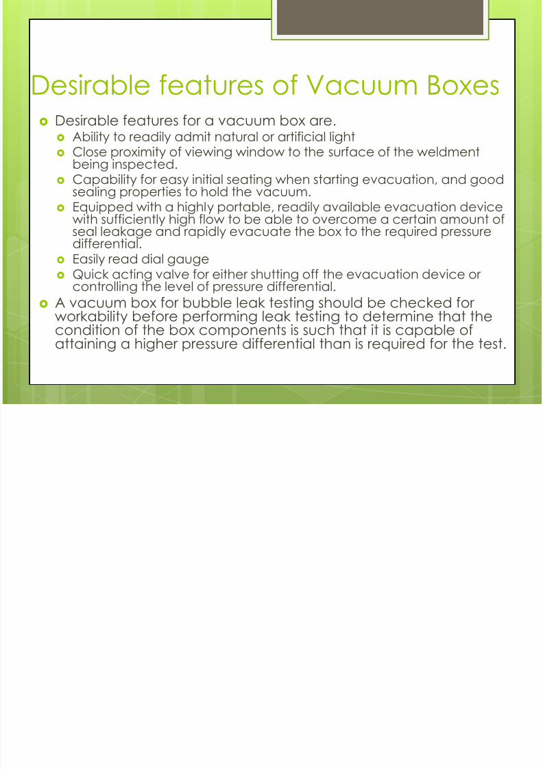
Desirable features of Vacuum Boxes Desirable features for a vacuum box are.
Ability to readily admit natural or artificial light Close proximity of viewing window to the surface of the weldment
being inspected. Capability for easy initial seating when starting evacuation, and good
sealing properties to hold the vacuum. Equipped with a highly portable, readily available evacuation device
with sufficiently high flow to be able to overcome a certain amount ofseal leakage and rapidly evacuate the box to the required pressuredifferential.
Easily read dial gauge Quick acting valve for either shutting off the evacuation device or
controlling the level of pressure differential. A vacuum box for bubble leak testing should be checked for
workability before performing leak testing to determine that thecondition of the box components is such that it is capable ofattaining a higher pressure differential than is required for the test.

7/27/2019 Chapter 4(Final)
http://slidepdf.com/reader/full/chapter-4final 6/53

7/27/2019 Chapter 4(Final)
http://slidepdf.com/reader/full/chapter-4final 7/53
Gaskets The gasket system used with a vacuum box is
critical to the ease with which the box can behandled and sealed to the test surface so as to be
able to hold a vacuum. The gasket must be shaped so that the initial area
of the gasket contact with the test surface is smallto make seating of the vacuum box easier.
Neoprene gaskets of 20 to 40 durometer providegood flexibility.

7/27/2019 Chapter 4(Final)
http://slidepdf.com/reader/full/chapter-4final 8/53

7/27/2019 Chapter 4(Final)
http://slidepdf.com/reader/full/chapter-4final 9/53

7/27/2019 Chapter 4(Final)
http://slidepdf.com/reader/full/chapter-4final 10/53

7/27/2019 Chapter 4(Final)
http://slidepdf.com/reader/full/chapter-4final 11/53

7/27/2019 Chapter 4(Final)
http://slidepdf.com/reader/full/chapter-4final 12/53
Hot Cathode Ionization Guage Ions are produced by collision of gas molecules by
hot filament.
These ions are accelerated by an electric field.
Gas ions are attracted to negatively charged ioncollector where they pick up electrons andbecome neutral molecule. This neutralizing electroncurrent is called ion current.
The magnitude of the ion current is an indication
of pressure.A conventional hot cathode ionization gauge
measures pressures in the range of10-3 to 10-10 mbar.

7/27/2019 Chapter 4(Final)
http://slidepdf.com/reader/full/chapter-4final 13/53
Hot Cathode Ionization
Gauge(Bayard – Alpert Ionizationgauge)

7/27/2019 Chapter 4(Final)
http://slidepdf.com/reader/full/chapter-4final 14/53

7/27/2019 Chapter 4(Final)
http://slidepdf.com/reader/full/chapter-4final 15/53

7/27/2019 Chapter 4(Final)
http://slidepdf.com/reader/full/chapter-4final 16/53

7/27/2019 Chapter 4(Final)
http://slidepdf.com/reader/full/chapter-4final 17/53
Evacuation system for Vacuum Box
Leak TestingA small box mounted air ejector connected to a
compressed air supply.
A small portable vacuum pump.
The vacuum box, when placed over theexamination area, should be evacuated at least35 kPa pressure differential with respect toatmospheric pressure.
The 35 kPa pressure differential can be verified bythe dial gauge.

7/27/2019 Chapter 4(Final)
http://slidepdf.com/reader/full/chapter-4final 18/53
Lighting Good lighting is necessary for the safety and reliability of
the test results.
Two general sources of lighting:
Artificial Lighting
For continuous shift operation, artificial light is essential.
For other types of operation, it must be relied upon from 20to 50% of the total working hours, excluding overtime work ornight work.
General Lighting
General lighting is the base or minimum amount of light
required. The uniform distribution of light to produce equivalent seeing
conditions throughout an interior.
Localized general lighting sources are arranged 3 meter ormore above the work to provide sufficient light for generalsafety and for ordinary visual needs.

7/27/2019 Chapter 4(Final)
http://slidepdf.com/reader/full/chapter-4final 19/53
Instruments for Pressure
MeasurementDead Weight Tester
The deadweight tester is a calibration standard for
measuring pressures.
Pressure or force per unit area is provided by known
weights acting on the known area of the cylinder.
Fluid pressure to be measured is applied against the
bottom of the piston, developing enough force to lift
the weights. Thus, the two factors of primary importance are the
weights used and the effective area of the piston
cylinder combination.

7/27/2019 Chapter 4(Final)
http://slidepdf.com/reader/full/chapter-4final 20/53
Instruments for Pressure
MeasurementManometers
Manometers are used to measure the fluid pressure.
The accuracy with which the fluid pressure can be
measured depends on.
Several factors that effect the weight of the fluid column
The accuracy with which the column height can be
measured.
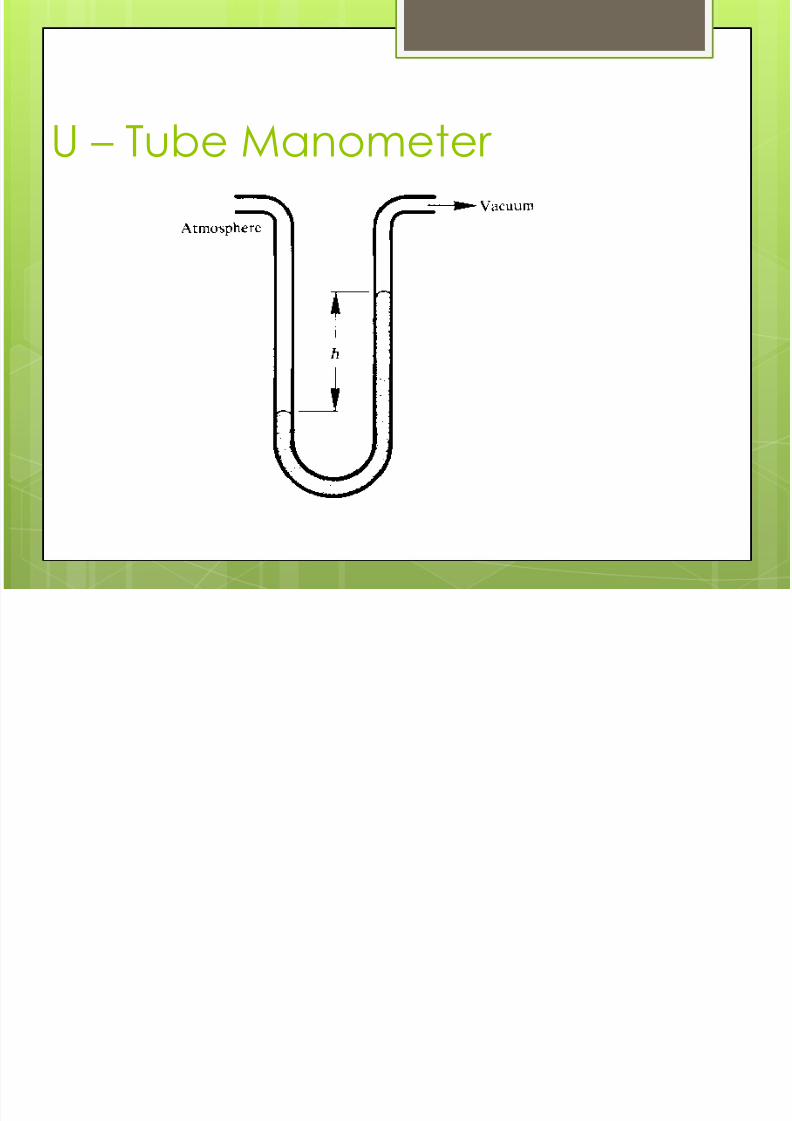
Difference in heights of mercury column in the two
legs of U – tube manometer is used measure the fluid
pressure.

7/27/2019 Chapter 4(Final)
http://slidepdf.com/reader/full/chapter-4final 21/53
Instruments for Pressure
MeasurementManometers
The difference in heights of the liquid in the two legs of
U-tube mercury manometer is exactly the same
whether: The diameter of the glass tube is the same in both legs.
The legs have different diameters, provided the diametersof the smaller tube does not approach capillary wheresurface tension effects come into play.
Difference in u – tube liquid column heights depends
on:
External pressure applied to the two sides of the u-tube
Density of liquid within the u-tube.
7/27/2019 Chapter 4(Final)
http://slidepdf.com/reader/full/chapter-4final 22/53
U – Tube Manometer

7/27/2019 Chapter 4(Final)
http://slidepdf.com/reader/full/chapter-4final 23/53
Absolute Pressure Dial Guages
Aneroid Capsules
Upto 350 kPa
Bourdon TubePressure Gauge
Above 350 kPa

7/27/2019 Chapter 4(Final)
http://slidepdf.com/reader/full/chapter-4final 24/53

7/27/2019 Chapter 4(Final)
http://slidepdf.com/reader/full/chapter-4final 25/53
Barometers Can be used to measure
absolute pressure. The simplest barometer consists
of a long tube which is sealed atone end.
The tube is filled with mercury,
then inverted and placed in apan filled with mercury. The mercury in the tube settles
down, leaving a vacuum aboveit.
The height of mercury column inthe tube above the level of the
mercury in the pan indicates theatmospheric pressure in inches ofmercury.
The height of mercury columnindicates atmospheric pressure.

7/27/2019 Chapter 4(Final)
http://slidepdf.com/reader/full/chapter-4final 26/53

7/27/2019 Chapter 4(Final)
http://slidepdf.com/reader/full/chapter-4final 27/53
Instruments for Temperature
Measurement An electrical resistance temperature detector (RTD) Used to measure internal air temperature in pressurized
systems Works on the principle of variation of electrical resistance
with variation in temperature. Thermocouple It is a bimetallic junction which produces an output
electromotive force (emf) that varies with its temperature. The millivolt readout of the thermocouple junction is
measured by means of a potentiometer and used todetermine a temperature reading from tables for that typeof thermocouple
The thermocouple is less desirable than resistancetemperature measuring devices from a stability andaccuracy standpoint.

7/27/2019 Chapter 4(Final)
http://slidepdf.com/reader/full/chapter-4final 28/53

7/27/2019 Chapter 4(Final)
http://slidepdf.com/reader/full/chapter-4final 29/53

7/27/2019 Chapter 4(Final)
http://slidepdf.com/reader/full/chapter-4final 30/53
Vacuum Pumps
Gas Transfer Pump
• Rotary vane pump
• Rotary pump
• Mechanical boosters
• Turbomolecualr pump
• Diffusion pump
Capture pumps
• Sorption pump
• Sublimation pump
• cryopump

7/27/2019 Chapter 4(Final)
http://slidepdf.com/reader/full/chapter-4final 31/53
Low andMediumVacuumPumps
The rotary van, rotary piston and
mechanical booster are all positivedisplacement types and are used tocreate low and medium level vacuum.
They (positive displacement pumps)
reduce the pressure in a system byrepeatedly taking samples of gas intothe pump.
The pump mechanism isolates the gasfrom the inlet, compresses it and thenexpels through an outlet.

7/27/2019 Chapter 4(Final)
http://slidepdf.com/reader/full/chapter-4final 32/53
Rotary Vane Pump (for creation of low to medium vacuum)
Most generally adopted in the vacuum industry today for the production ofpressure down to 10-2 to 10-3 mbar.
The mechanism, which is lubricated by oil, consists of a housing with a cylindricalbore into which is fitted a rotor.
The rotor is offset in a relation to the stator bore and fits closely against the statorin one position.
The stator bore in this area has a curvature equal to that of the rotor accuratelymachined across the whole width of the stator bore.
The rotor contains two blades which slide in diametrically opposed slots. Thus, asthe rotor turns, the tips of the blades are in contact with the stator wall at all times.

7/27/2019 Chapter 4(Final)
http://slidepdf.com/reader/full/chapter-4final 33/53
Rotary Vane Pump (for creation of low to medium vacuum)
The cycle is divided into induction, isolation,compression and exhaust phases. During
operation gas molecules entering the inlet of
the pump pass into the volume created by theeccentric mounting of the rotor in the stator.
The crescent shaped gas volume is then compressed, forcingthe exhaust valve open and permitting gas discharge.
In another version of this pump, improved performance is achievedby using two stages in series to produce are two stage pump. The firstor high vacuum stage, is ‘backed’ by the second or low vacuum
stage via an internal transfer duct. With this arrangement the pressureat the exhaust port of the high vacuum stage is considerably less
than atmospheric pressure when the inlet pressure is low.

7/27/2019 Chapter 4(Final)
http://slidepdf.com/reader/full/chapter-4final 34/53
7/27/2019 Chapter 4(Final)
http://slidepdf.com/reader/full/chapter-4final 35/53

7/27/2019 Chapter 4(Final)
http://slidepdf.com/reader/full/chapter-4final 36/53
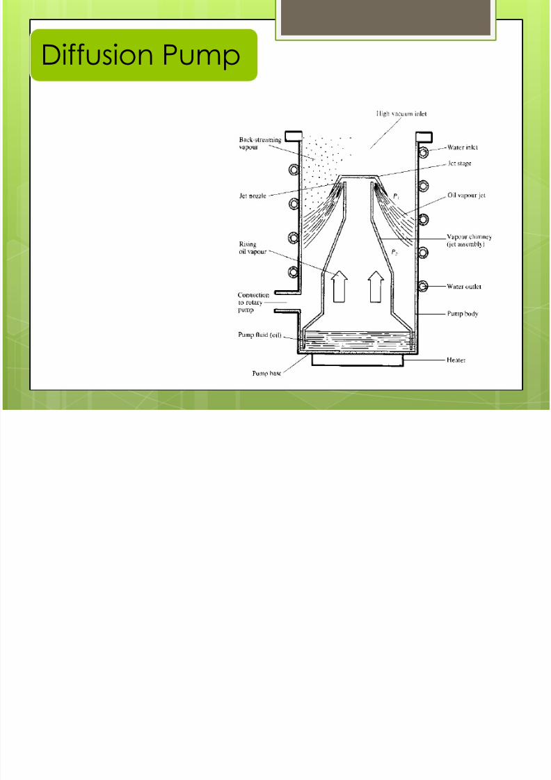
Diffusion Pump
Here gas transport is achieved by
a series of high velocity vapour jets, emerging from an assemblywithin the pump body. In normaloperation a portion of any gas
arriving at the inlet jet isentrained, compressed andtransferred to the next stage.
7/27/2019 Chapter 4(Final)
http://slidepdf.com/reader/full/chapter-4final 37/53

7/27/2019 Chapter 4(Final)
http://slidepdf.com/reader/full/chapter-4final 38/53
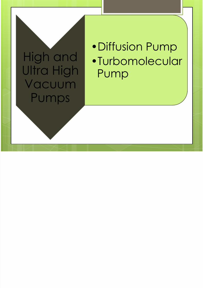
Turbomolecular Pump
Turbo molecular pump consists of a rotor with inclinedblades moving at high speed between corresponding
stationary blades in a stator. Gas molecules entering the
inlet port acquire a velocity and preferred directionsuperimposed on their velocity by repeated collisions with
the fast moving rotor. Rotational speeds for small pumps aretypically 60,000 revolutions per minute.
All high vacuum pumps operate in the molecular flow region.
The pump must be rough pumped before they can be started.High Vacuum pumping system for general purpose or fast
cycling duties would most likely employ diffusion orTurbomolecular pumps.
For dirty conditions the diffusion pump would be the first choice.

7/27/2019 Chapter 4(Final)
http://slidepdf.com/reader/full/chapter-4final 39/53

7/27/2019 Chapter 4(Final)
http://slidepdf.com/reader/full/chapter-4final 40/53

7/27/2019 Chapter 4(Final)
http://slidepdf.com/reader/full/chapter-4final 41/53

7/27/2019 Chapter 4(Final)
http://slidepdf.com/reader/full/chapter-4final 42/53

7/27/2019 Chapter 4(Final)
http://slidepdf.com/reader/full/chapter-4final 43/53
Vacuum Connectors
•Grooved flanges are used to issue the leak tight system and
less compression such grooves should meet the followingrequirements.
•The cross-section of the groove should be of the order of 10percent greater than the cross section of the ‘O’ ring, toallow for a metal to metal flange contact withoutovercompressing the ‘O’ ring.
•To provide positive retention of the gasket, when the seal isnot ‘made’.
•To provide the minimum volume of trapped gas.
•To allow reuse of the ‘O’ ring after the seal is broken. In thisrespect, overcompression or grooves with sharp corner or
acute angles are of bad design as this leads to permanentdeformation or cutting of the ‘O’ ring.
•To permit easy flange machining end to wide machinetolerance.
•O – rings generally provide better sealing than flat gaskets.

7/27/2019 Chapter 4(Final)
http://slidepdf.com/reader/full/chapter-4final 44/53
Vacuum Connector
Hinged Clamps
These clamps are
used for quick
release
applications

7/27/2019 Chapter 4(Final)
http://slidepdf.com/reader/full/chapter-4final 45/53
•Common functions of commerciallyavailable mass spectrometer leakdetector instruments are:
•Pumping tracer gas samples fromleaks in test objects into the vacuumof the instrument.
•The ionization of gas samplemolecules by electron impact.
•The sorting and identification ofpositive ions according to their mass-to-charge ratios.
Mass Spectrometer

7/27/2019 Chapter 4(Final)
http://slidepdf.com/reader/full/chapter-4final 46/53
Mass Spectrometer Tube

7/27/2019 Chapter 4(Final)
http://slidepdf.com/reader/full/chapter-4final 47/53
Sniffer
It is a simple tracer gas collectiondevice
It is connected to leak detector witha pumping device.
The pump provides the suctionnecessary to draw tracer gas samplesto the sniffer inlet through theconnecting hose and into the sensingelement of the leak detector.

7/27/2019 Chapter 4(Final)
http://slidepdf.com/reader/full/chapter-4final 48/53
Compound mastics for sealing to vacuum
Apiezon Type(hydrocarbon) Silicone type Fomblin
Good lubricant Yes No Yes
Vapour pressure(mbar) Low Approx. 10-6 Low
Temperaturesuitability 125C max. -40 to 200C -02 to 200C
Cost Moderate Low High
Chemical stability Moderate Good Very good

7/27/2019 Chapter 4(Final)
http://slidepdf.com/reader/full/chapter-4final 49/53

7/27/2019 Chapter 4(Final)
http://slidepdf.com/reader/full/chapter-4final 50/53

7/27/2019 Chapter 4(Final)
http://slidepdf.com/reader/full/chapter-4final 51/53

7/27/2019 Chapter 4(Final)
http://slidepdf.com/reader/full/chapter-4final 52/53

7/27/2019 Chapter 4(Final)
http://slidepdf.com/reader/full/chapter-4final 53/53