Embed Size (px)
Citation preview

Zhang, R. "Seismic Isolation and Supplemental Energy Dissipation." Bridge Engineering Handbook. Ed. Wai-Fah Chen and Lian Duan Boca Raton: CRC Press, 2000

41Seismic Isolation
and SupplementalEnergy Dissipation
41.1 Introduction
41.2 Basic Concepts, Modeling, and Analysis Earthquake Response Spectrum Analysis • Structural Dynamic Response Modifications • Modeling of Seismically Isolated Structures • Effect of Energy Dissipation on Structural Dynamic Response
41.3 Seismic Isolation and Energy Dissipation DevicesElastomeric Isolators • Sliding Isolators • Viscous Fluid Dampers • Viscoelastic Dampers • Other Types of Damping Devices
41.4 Performance and Testing RequirmentsSeismic Isolation Devices • Testing of Energy Dissipation Devices
41.5 Design Guidelines and Design ExamplesSeismic Isolation Design Specifications and Examples • Guidelines for Energy Dissipation Devices Design
41.6 Recent Developments and Applications Practical Applications of Seismic IsolationApplications of Energy Dissipation Devices to Bridges
41.7 Summary
41.1 Introduction
Strong earthquakes impart substantial amounts of energy into structures and may cause the struc-tures to deform excessively or even collapse. In order for structures to survive, they must have thecapability to dissipate this input energy through either their inherent damping mechanism orinelastic deformation. This issue of energy dissipation becomes even more acute for bridge structuresbecause most bridges, especially long-span bridges, possess very low inherent damping, usually lessthan 5% of critical. When these structures are subjected to strong earthquake motions, excessivedeformations can occur by relying on only inherent damping and inelastic deformation. For bridgesdesigned mainly for gravity and service loads, excessive deformation leads to severe damage or evencollapse. In the instances of major bridge crossings, as was the case of the San Francisco–Oakland
Rihui ZhangCalifornia State Department
of Transportation
© 2000 by CRC Press LLC

Bay Bridge during the 1989 Loma Prieta earthquake, even noncollapsing structural damage maycause very costly disruption to traffic on major transportation arteries and is simply unacceptable.
Existing bridge seismic design standards and specifications are based on the philosophy of accept-ing minor or even major damage but no structural collapse. Lessons learned from recent earthquakedamage to bridge structures have resulted in the revision of these design standards and a change ofdesign philosophy. For example, the latest bridge design criteria for California [1] recommend theuse of a two-level performance criterion which requires that a bridge be designed for both safetyevaluation and functional evaluation design earthquakes. A safety evaluation earthquake event isdefined as an event having a very low probability of occurring during the design life of the bridge.For this design earthquake, a bridge is expected to suffer limited significant damage, or immediatelyrepairable damage. A functional evaluation earthquake event is defined as an event having a rea-sonable probability of occurring once or more during the design life of the bridge. Damages sufferedunder this event should be immediately repairable or immediate minimum for important bridges.These new criteria have been used in retrofit designs of major toll bridges in the San Francisco Bayarea and in designs of some new bridges. These design criteria have placed heavier emphasis oncontrolling the behavior of bridge structural response to earthquake ground motions.
For many years, efforts have been made by the structural engineering community to search forinnovative ways to control how earthquake input energy is absorbed by a structure and hencecontrolling its response to earthquake ground motions. These efforts have resulted in the develop-ment of seismic isolation techniques, various supplemental energy dissipation devices, and activestructural control techniques. Some applications of these innovative structural control techniqueshave proved to be cost-effective. In some cases, they may be the only ways to achieve a satisfactorysolution. Furthermore, with the adoption of new performance-based design criteria, there will sooncome a time when these innovative structural control technologies will be the choice of morestructural engineers because they offer economical alternatives to traditional earthquake protectionmeasures.
Topics of structural response control by passive and active measures have been covered by severalauthors for general structural applications [2–4]. This chapter is devoted to the developments andapplications of these innovative technologies to bridge structures. Following a presentation of thebasic concepts, modeling, and analysis methods, brief descriptions of major types of isolation andenergy dissipation devices are given. Performance and testing requirements will be discussed fol-lowed by a review of code developments and design procedures. A design example will also be givenfor illustrative purposes.
41.2 Basic Concepts, Modeling, and Analysis
The process of a structure responding to earthquake ground motions is actually a process involvingresonance buildup to some extent. The severity of resonance is closely related to the amount ofenergy and its frequency content in the earthquake loading. Therefore, controlling the response ofa structure can be accomplished by either finding ways to prevent resonance from building up orproviding a supplemental energy dissipation mechanism, or both. Ideally, if a structure can beseparated from the most-damaging energy content of the earthquake input, then the structure issafe. This is the idea behind seismic isolation. An isolator placed between the bridge superstructureand its supporting substructure, in the place of a traditional bearing device, substantially lengthensthe fundamental period of the bridge structure such that the bridge does not respond to the most-damaging energy content of the earthquake input. Most of the deformation occurs across the isolatorinstead of in the substructure members, resulting in lower seismic demand for substructure mem-bers. If it is impossible to separate the structure from the most-damaging energy content, then theidea of using supplemental damping devices to dissipate earthquake input energy and to reducestructural damage becomes very attractive.
© 2000 by CRC Press LLC
In what follows, theoretical basis and modeling and analysis methods will be presented mainlybased on the concept of earthquake response spectrum analysis.
41.2.1 Earthquake Response Spectrum Analysis
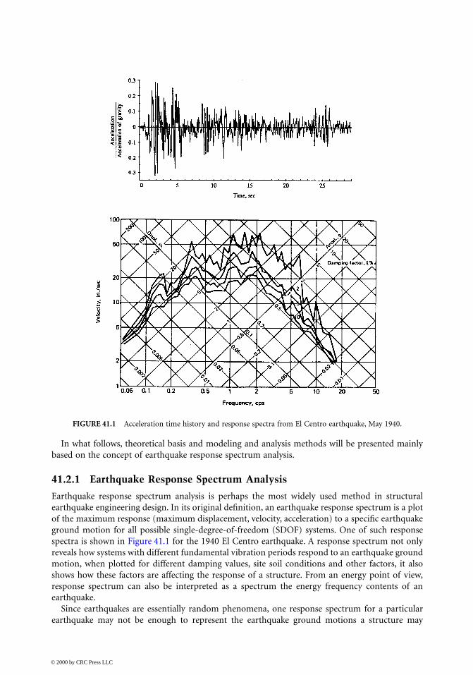
Earthquake response spectrum analysis is perhaps the most widely used method in structuralearthquake engineering design. In its original definition, an earthquake response spectrum is a plotof the maximum response (maximum displacement, velocity, acceleration) to a specific earthquakeground motion for all possible single-degree-of-freedom (SDOF) systems. One of such responsespectra is shown in Figure 41.1 for the 1940 El Centro earthquake. A response spectrum not onlyreveals how systems with different fundamental vibration periods respond to an earthquake groundmotion, when plotted for different damping values, site soil conditions and other factors, it alsoshows how these factors are affecting the response of a structure. From an energy point of view,response spectrum can also be interpreted as a spectrum the energy frequency contents of anearthquake.
Since earthquakes are essentially random phenomena, one response spectrum for a particularearthquake may not be enough to represent the earthquake ground motions a structure may
FIGURE 41.1 Acceleration time history and response spectra from El Centro earthquake, May 1940.
© 2000 by CRC Press LLC

experience during its service life. Therefore, the design spectrum, which incorporates responsespectra for several earthquakes and hence represents a kind of “average” response, is generally usedin seismic design. These design spectra generally appear to be smooth or to consist of a series ofstraight lines. Detailed discussion of the construction and use of design spectra is beyond the scopeof this chapter; further information can be found in References [5,6]. It suffices to note for thepurpose of this chapter that design spectra may be used in seismic design to determine the responseof a structure to a design earthquake with given intensity (maximum effective ground acceleration)from the natural period of the structure, its damping level, and other factors. Figure 41.2 shows asmoothed design spectrum curve based on the average shapes of response spectra of several strongearthquakes.
41.2.2 Structural Dynamic Response Modifications
By observing the response/design spectra in Figures 41.1a, it is seen that manipulating the naturalperiod and/or the damping level of a structure can effectively modify its dynamic response. Byinserting a relatively flexible isolation bearing in place of a conventional bridge bearing between abridge superstructure and its supporting substructure, seismic isolation bearings are able to lengthenthe natural period of the bridge from a typical value of less than 1 second to 3 to 5 s. This willusually result in a reduction of earthquake-induced response and force by factors of 3 to 8 fromthose of fixed-support bridges [7].
As for the effect of damping, most bridge structures have very little inherent material damping,usually in the range of 1 to 5% of critical. The introduction of nonstructural damping becomesnecessary to reduce the response of a structure.
Some kind of a damping device or mechanism is also a necessary component of any successfulseismic isolation system. As mentioned earlier, in an isolated structural system deformation mainlyoccurs across the isolator. Many factors limit the allowable deformation taking place across an
FIGURE 41.2 Example of smoothed design spectrum.
© 2000 by CRC Press LLC
isolator, e.g., space limitation, stability requirement, etc. To control deformation of the isolators,supplemental damping is often introduced in one form or another into isolation systems.
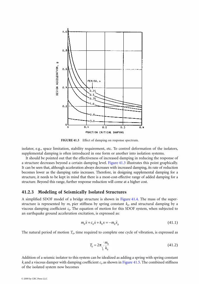
It should be pointed out that the effectiveness of increased damping in reducing the response ofa structure decreases beyond a certain damping level. Figure 41.3 illustrates this point graphically.It can be seen that, although acceleration always decreases with increased damping, its rate of reductionbecomes lower as the damping ratio increases. Therefore, in designing supplemental damping for astructure, it needs to be kept in mind that there is a most-cost-effective range of added damping for astructure. Beyond this range, further response reduction will come at a higher cost.
41.2.3 Modeling of Seismically Isolated Structures
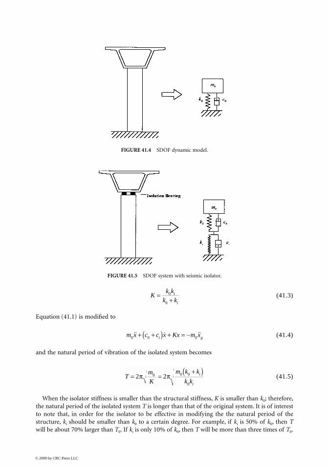
A simplified SDOF model of a bridge structure is shown in Figure 41.4. The mass of the super-structure is represented by m, pier stiffness by spring constant k0, and structural damping by aviscous damping coefficient c0. The equation of motion for this SDOF system, when subjected toan earthquake ground acceleration excitation, is expressed as:
(41.1)
The natural period of motion T0, time required to complete one cycle of vibration, is expressed as
(41.2)
Addition of a seismic isolator to this system can be idealized as adding a spring with spring constantki and a viscous damper with damping coefficient ci, as shown in Figure 41.5. The combined stiffnessof the isolated system now becomes
FIGURE 41.3 Effect of damping on response spectrum.
m x c x k x m xg0 0 0 0˙̇ ˙ ˙̇+ + = −
Tm
k00
0
2= π
© 2000 by CRC Press LLC
(41.3)
Equation (41.1) is modified to
(41.4)
and the natural period of vibration of the isolated system becomes
(41.5)
When the isolator stiffness is smaller than the structural stiffness, K is smaller than k0; therefore,the natural period of the isolated system T is longer than that of the original system. It is of interestto note that, in order for the isolator to be effective in modifying the the natural period of thestructure, ki should be smaller than k0 to a certain degree. For example, if ki is 50% of k0, then Twill be about 70% larger than T0. If ki is only 10% of k0, then T will be more than three times of T0.
FIGURE 41.4 SDOF dynamic model.
FIGURE 41.5 SDOF system with seismic isolator.
Kk k
k ki
i
=+0
0
m x c c x Kx m xi g0 0 0˙̇ ˙ ˙̇+ +( ) + = −
Tm
K
m k k
k ki
i
= =+( )
2 20 0 0
0
π π
© 2000 by CRC Press LLC
More complex structural systems will have to be treated as multiple-degree-of-freedom (MDOF)systems; however, the principle is the same. In these cases, spring elements will be added toappropriate locations to model the stiffness of the isolators.
41.2.4 Effect of Energy Dissipation on Structural Dynamic Response
In discussing energy dissipation, the terms damping and energy dissipation will be used interchange-ably. Consider again the simple SDOF system used in the previous discussion. In the theory ofstructural dynamics [8], critical value of damping coefficient cc is defined as the amount of dampingthat will prevent a dynamic system from free oscillation response. This critical damping value canbe expressed in terms of the system mass and stiffness:
(41.6)
With respect to this critical damping coefficient, any amount of damping can now be expressed ina relative term called damping ratio ξ, which is the ratio of actual system damping coefficient overthe critical damping coefficient. Thus,
(41.7)
Damping ratio is usually expressed as a percentage of the critical. With the use of damping ratio,one can compare the amount of damping of different dynamic systems.
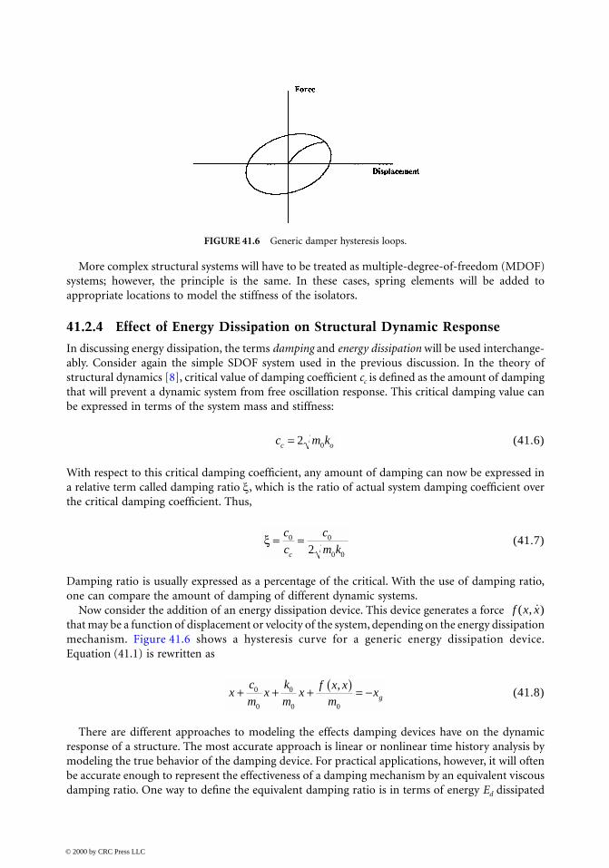
Now consider the addition of an energy dissipation device. This device generates a force that may be a function of displacement or velocity of the system, depending on the energy dissipationmechanism. Figure 41.6 shows a hysteresis curve for a generic energy dissipation device.Equation (41.1) is rewritten as
(41.8)
There are different approaches to modeling the effects damping devices have on the dynamicresponse of a structure. The most accurate approach is linear or nonlinear time history analysis bymodeling the true behavior of the damping device. For practical applications, however, it will oftenbe accurate enough to represent the effectiveness of a damping mechanism by an equivalent viscousdamping ratio. One way to define the equivalent damping ratio is in terms of energy Ed dissipated
FIGURE 41.6 Generic damper hysteresis loops.
c m kc o= 2 0
ξ = =c
c
c
m kc
0 0
0 02
f x x( , ˙)
xc
mx
k
mx
f x xm
xg+ + + ( ) = −0
0
0
0 0
,
© 2000 by CRC Press LLC
by the device in one cycle of cyclic motion over the maximum strain energy Ems stored in thestructure [8]:
(41.9)
For a given device, Ed can be found by measuring the area of the hysteresis loop. Equation (41.9)can now be rewritten by introducing damping ratio ξ0 and ξeq, in the form
(41.10)
This concept of equivalent viscous damping ratio can also be generalized to use for MDOF systemsby considering ξeq as modal damping ratio and Ed and Ems as dissipated energy and maximum strainenergy in each vibration mode [9]. Thus, for the ith vibration mode of a structure, we have
(41.11)
Now the dynamic response of a structure with supplemental damping can be solved using availablelinear analysis techniques, be it linear time history analysis or response spectrum analysis.
41.3 Seismic Isolation and Energy Dissipation Devices
Many different types of seismic isolation and supplemental energy dissipation devices have beendeveloped and tested for seismic applications over the last three decades, and more are still beinginvestigated. Their basic behaviors and applications for some of the more widely recognized andused devices will be presented in this section.
41.3.1 Elastomeric Isolators
Elastomeric isolators, in their simplest form, are elastomeric bearings made from rubber, typicallyin cylindrical or rectangular shapes. When installed on bridge piers or abutments, the elastomericbearings serve both as vertical bearing devices for service loads and lateral isolation devices forseismic load. This requires that the bearings be stiff with respect to vertical loads but relativelyflexible with respect to lateral seismic loads. In order to be flexible, the isolation bearings have tobe made much thicker than the elastomeric bearing pads used in conventional bridge design.Insertion of horizontal steel plates, as in the case of steel reinforced elastomeric bearing pads,significantly increases vertical stiffness of the bearing and improves stability under horizontal loads.The total rubber thickness influences essentially the maximum allowable lateral displacement andthe period of vibration.
For a rubber bearing with given bearing area A, shear modulus G, height h, allowable shear strainγ, shape factor S, and bulk modulus K, its horizontal stiffness and period of vibration can beexpressed as
(41.12)
ξπ
eqd
ms
E
E=
4
˙̇ ˙ ˙̇xk
mx
k
mx xeq g+ +( ) + = −2 0 0
0
ξ ξ
ξπeq
i di
msi
E
E=
4
KGAh
=
© 2000 by CRC Press LLC
(41.13)
where A′ is the overlap of top and bottom areas of a bearing at maximum displacement. Typicalvalues for bridge elastomeric bearing properties are G = 1 MPa (145 psi), K = 200 MPa (290 psi),γ = 0.9 to 1.4, S = 3 to 40. The major variability lies in S, which is a function of plan dimensionand rubber layer thickness.
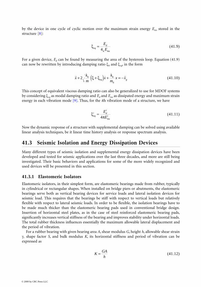
One problem associated with using pure rubber bearings for seismic isolation is that the bearingcould easily experience excessive deformation during a seismic event. This will, in many cases,jeopardize the stability of the bearing and the superstructure it supports. One solution is to add anenergy dissipation device or mechanism to the isolation bearing. The most widely used energydissipation mechanism in elastomeric isolation bearing is the insertion of a lead core at the centerof the bearing. Lead has a high initial shear stiffness and relatively low shear yielding strength. Itessentially has elastic–plastic behavior with good fatigue properties for plastic cycles. It provides ahigh horizontal stiffness for service load resistance and a high energy dissipation for strong seismicload, making it ideal for use with elastomeric bearings.
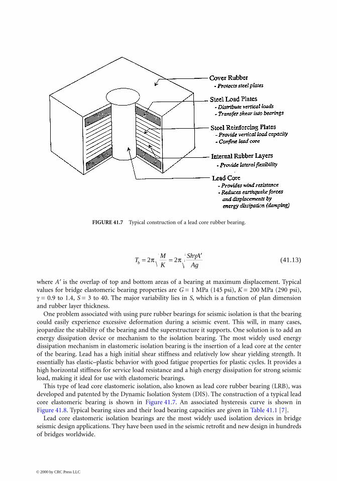
This type of lead core elastomeric isolation, also known as lead core rubber bearing (LRB), wasdeveloped and patented by the Dynamic Isolation System (DIS). The construction of a typical leadcore elastomeric bearing is shown in Figure 41.7. An associated hysteresis curve is shown inFigure 41.8. Typical bearing sizes and their load bearing capacities are given in Table 41.1 [7].
Lead core elastomeric isolation bearings are the most widely used isolation devices in bridgeseismic design applications. They have been used in the seismic retrofit and new design in hundredsof bridges worldwide.
FIGURE 41.7 Typical construction of a lead core rubber bearing.
TMK
Sh AAgb = = ′
2 2π π γ
© 2000 by CRC Press LLC
41.3.2 Sliding Isolators
Sliding-type isolation bearings reduce the force transferred from superstructure to the supportingsubstructure when subject to earthquake excitations by allowing the superstructure to slide on alow friction surface usually made from stainless steel-PTFE. The maximum friction between thesliding surfaces limits the maximum force that can be transferred by the bearing. The frictionbetween the surfaces will also dissipate energy. A major concern with relying only on simple slidingbearings for seismic application is the lack of centering force to restore the structure to its undis-placed position together with poor predictability and reliability of the response. This can beaddressed by combining the slider with spring elements or, as in the case of friction pendulumisolation (FPI) bearings, by making the sliding surface curved such that the self-weight of thestructure will help recenter the superstructure. In the following, the FPI bearings by EarthquakeProtection Systems (EPS) will be presented as a representative of sliding-type isolation bearings.
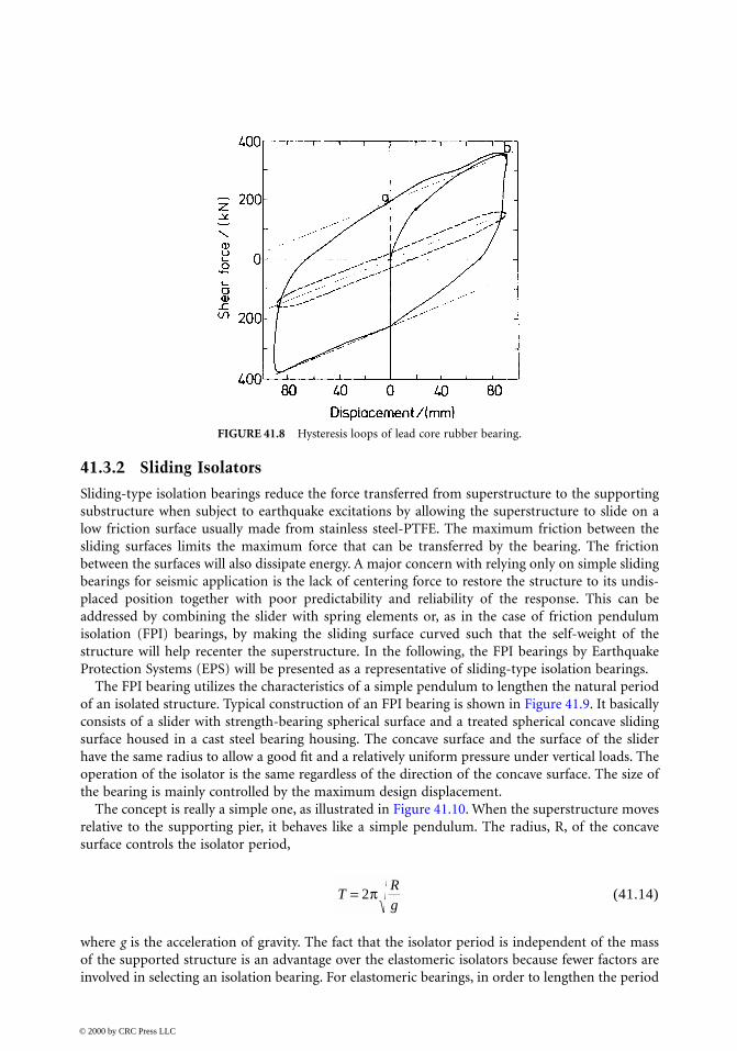
The FPI bearing utilizes the characteristics of a simple pendulum to lengthen the natural periodof an isolated structure. Typical construction of an FPI bearing is shown in Figure 41.9. It basicallyconsists of a slider with strength-bearing spherical surface and a treated spherical concave slidingsurface housed in a cast steel bearing housing. The concave surface and the surface of the sliderhave the same radius to allow a good fit and a relatively uniform pressure under vertical loads. Theoperation of the isolator is the same regardless of the direction of the concave surface. The size ofthe bearing is mainly controlled by the maximum design displacement.
The concept is really a simple one, as illustrated in Figure 41.10. When the superstructure movesrelative to the supporting pier, it behaves like a simple pendulum. The radius, R, of the concavesurface controls the isolator period,
(41.14)
where g is the acceleration of gravity. The fact that the isolator period is independent of the massof the supported structure is an advantage over the elastomeric isolators because fewer factors areinvolved in selecting an isolation bearing. For elastomeric bearings, in order to lengthen the period
FIGURE 41.8 Hysteresis loops of lead core rubber bearing.
TRg
= 2π
© 2000 by CRC Press LLC
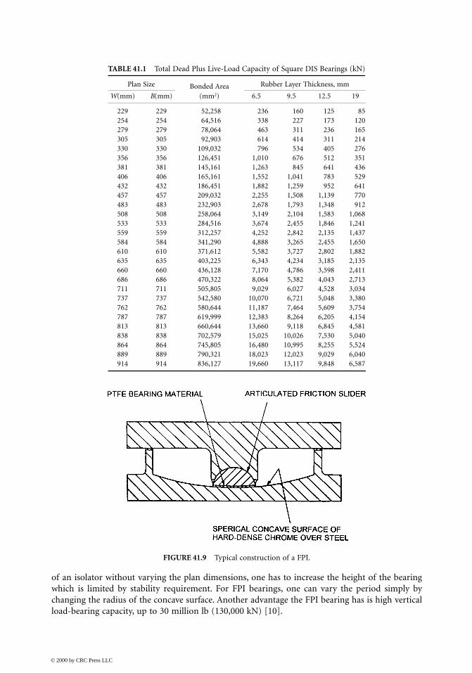
of an isolator without varying the plan dimensions, one has to increase the height of the bearingwhich is limited by stability requirement. For FPI bearings, one can vary the period simply bychanging the radius of the concave surface. Another advantage the FPI bearing has is high verticalload-bearing capacity, up to 30 million lb (130,000 kN) [10].
TABLE 41.1 Total Dead Plus Live-Load Capacity of Square DIS Bearings (kN)
Plan Size Bonded Area (mm2)
Rubber Layer Thickness, mm
W(mm) B(mm) 6.5 9.5 12.5 19
229 229 52,258 236 160 125 85254 254 64,516 338 227 173 120279 279 78,064 463 311 236 165305 305 92,903 614 414 311 214330 330 109,032 796 534 405 276356 356 126,451 1,010 676 512 351381 381 145,161 1,263 845 641 436406 406 165,161 1,552 1,041 783 529432 432 186,451 1,882 1,259 952 641457 457 209,032 2,255 1,508 1,139 770483 483 232,903 2,678 1,793 1,348 912508 508 258,064 3,149 2,104 1,583 1,068533 533 284,516 3,674 2,455 1,846 1,241559 559 312,257 4,252 2,842 2,135 1,437584 584 341,290 4,888 3,265 2,455 1,650610 610 371,612 5,582 3,727 2,802 1,882635 635 403,225 6,343 4,234 3,185 2,135660 660 436,128 7,170 4,786 3,598 2,411686 686 470,322 8,064 5,382 4,043 2,713711 711 505,805 9,029 6,027 4,528 3,034737 737 542,580 10,070 6,721 5,048 3,380762 762 580,644 11,187 7,464 5,609 3,754787 787 619,999 12,383 8,264 6,205 4,154813 813 660,644 13,660 9,118 6,845 4,581838 838 702,579 15,025 10,026 7,530 5,040864 864 745,805 16,480 10,995 8,255 5,524889 889 790,321 18,023 12,023 9,029 6,040914 914 836,127 19,660 13,117 9,848 6,587
FIGURE 41.9 Typical construction of a FPI.
© 2000 by CRC Press LLC
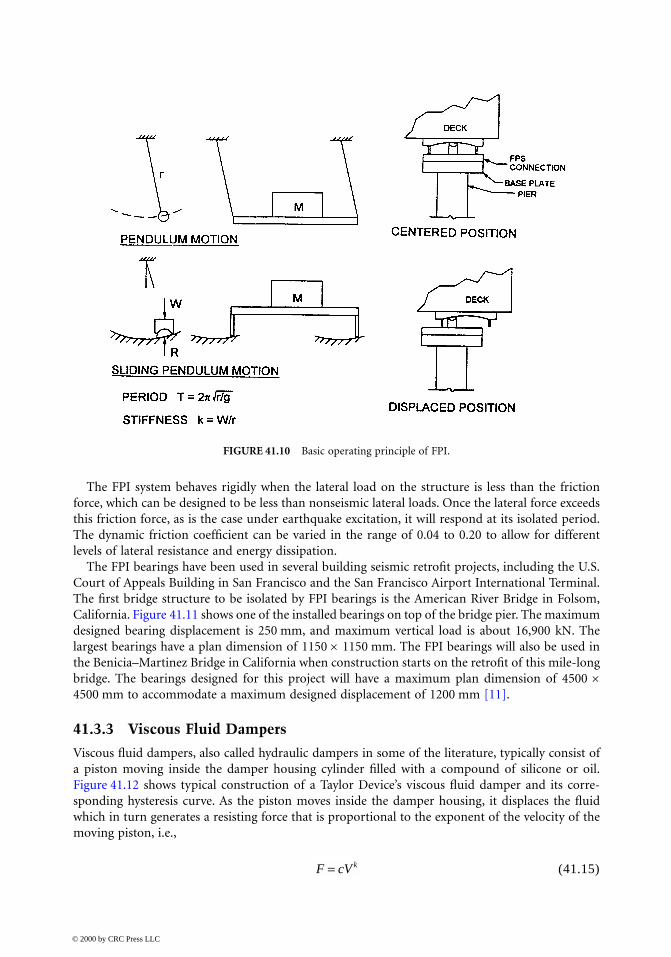
The FPI system behaves rigidly when the lateral load on the structure is less than the frictionforce, which can be designed to be less than nonseismic lateral loads. Once the lateral force exceedsthis friction force, as is the case under earthquake excitation, it will respond at its isolated period.The dynamic friction coefficient can be varied in the range of 0.04 to 0.20 to allow for differentlevels of lateral resistance and energy dissipation.
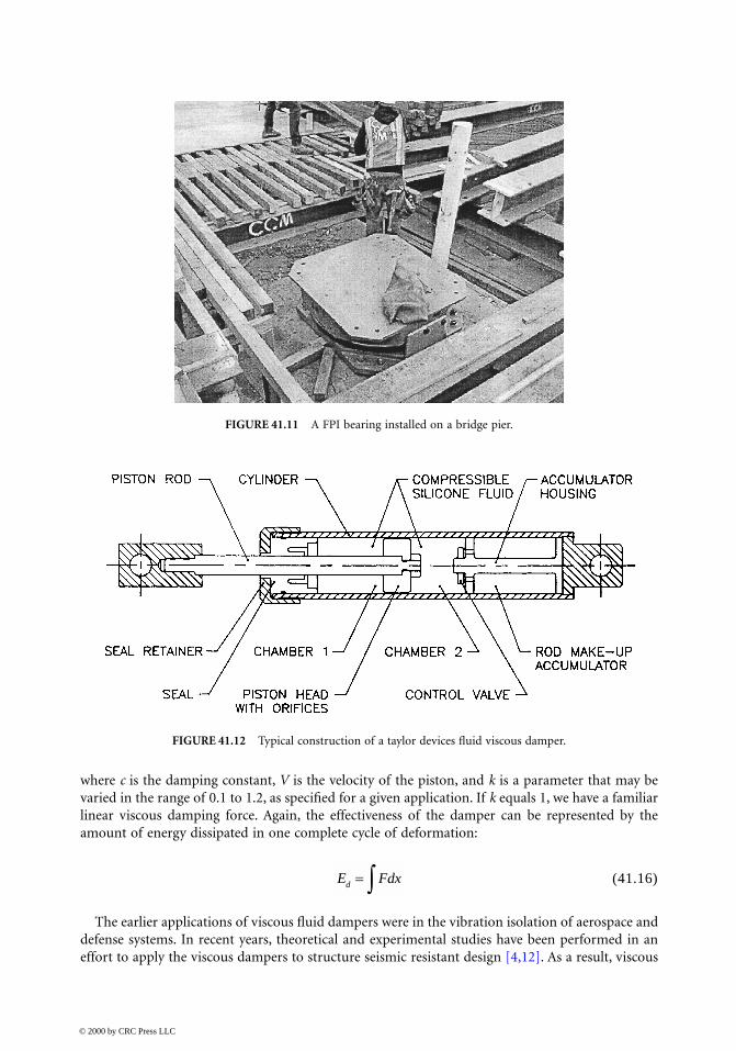
The FPI bearings have been used in several building seismic retrofit projects, including the U.S.Court of Appeals Building in San Francisco and the San Francisco Airport International Terminal.The first bridge structure to be isolated by FPI bearings is the American River Bridge in Folsom,California. Figure 41.11 shows one of the installed bearings on top of the bridge pier. The maximumdesigned bearing displacement is 250 mm, and maximum vertical load is about 16,900 kN. Thelargest bearings have a plan dimension of 1150 × 1150 mm. The FPI bearings will also be used inthe Benicia–Martinez Bridge in California when construction starts on the retrofit of this mile-longbridge. The bearings designed for this project will have a maximum plan dimension of 4500 ×4500 mm to accommodate a maximum designed displacement of 1200 mm [11].
41.3.3 Viscous Fluid Dampers
Viscous fluid dampers, also called hydraulic dampers in some of the literature, typically consist ofa piston moving inside the damper housing cylinder filled with a compound of silicone or oil.Figure 41.12 shows typical construction of a Taylor Device’s viscous fluid damper and its corre-sponding hysteresis curve. As the piston moves inside the damper housing, it displaces the fluidwhich in turn generates a resisting force that is proportional to the exponent of the velocity of themoving piston, i.e.,
(41.15)
FIGURE 41.10 Basic operating principle of FPI.
F cV k=
© 2000 by CRC Press LLC
where c is the damping constant, V is the velocity of the piston, and k is a parameter that may bevaried in the range of 0.1 to 1.2, as specified for a given application. If k equals 1, we have a familiarlinear viscous damping force. Again, the effectiveness of the damper can be represented by theamount of energy dissipated in one complete cycle of deformation:
(41.16)
The earlier applications of viscous fluid dampers were in the vibration isolation of aerospace anddefense systems. In recent years, theoretical and experimental studies have been performed in aneffort to apply the viscous dampers to structure seismic resistant design [4,12]. As a result, viscous
FIGURE 41.11 A FPI bearing installed on a bridge pier.
FIGURE 41.12 Typical construction of a taylor devices fluid viscous damper.
E Fdxd = ∫
© 2000 by CRC Press LLC
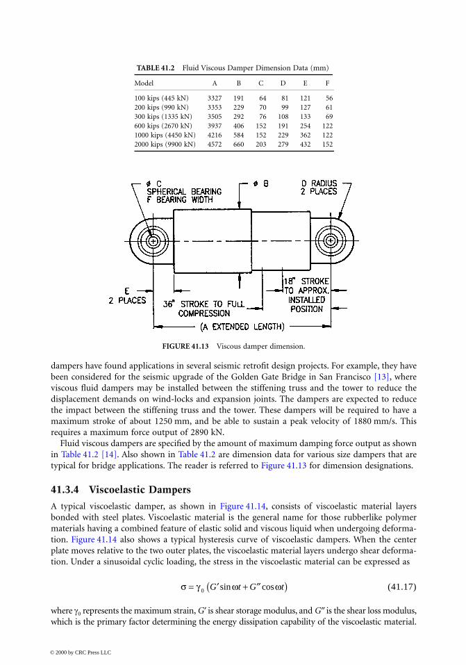
dampers have found applications in several seismic retrofit design projects. For example, they havebeen considered for the seismic upgrade of the Golden Gate Bridge in San Francisco [13], whereviscous fluid dampers may be installed between the stiffening truss and the tower to reduce thedisplacement demands on wind-locks and expansion joints. The dampers are expected to reducethe impact between the stiffening truss and the tower. These dampers will be required to have amaximum stroke of about 1250 mm, and be able to sustain a peak velocity of 1880 mm/s. Thisrequires a maximum force output of 2890 kN.
Fluid viscous dampers are specified by the amount of maximum damping force output as shownin Table 41.2 [14]. Also shown in Table 41.2 are dimension data for various size dampers that aretypical for bridge applications. The reader is referred to Figure 41.13 for dimension designations.
41.3.4 Viscoelastic Dampers
A typical viscoelastic damper, as shown in Figure 41.14, consists of viscoelastic material layersbonded with steel plates. Viscoelastic material is the general name for those rubberlike polymermaterials having a combined feature of elastic solid and viscous liquid when undergoing deforma-tion. Figure 41.14 also shows a typical hysteresis curve of viscoelastic dampers. When the centerplate moves relative to the two outer plates, the viscoelastic material layers undergo shear deforma-tion. Under a sinusoidal cyclic loading, the stress in the viscoelastic material can be expressed as
(41.17)
where γ0 represents the maximum strain, G′ is shear storage modulus, and G″ is the shear loss modulus,which is the primary factor determining the energy dissipation capability of the viscoelastic material.
TABLE 41.2 Fluid Viscous Damper Dimension Data (mm)
Model A B C D E F
100 kips (445 kN) 3327 191 64 81 121 56200 kips (990 kN) 3353 229 70 99 127 61300 kips (1335 kN) 3505 292 76 108 133 69600 kips (2670 kN) 3937 406 152 191 254 1221000 kips (4450 kN) 4216 584 152 229 362 1222000 kips (9900 kN) 4572 660 203 279 432 152
FIGURE 41.13 Viscous damper dimension.
σ γ ω ω= ′ + ′′( )0 G t G tsin cos
© 2000 by CRC Press LLC
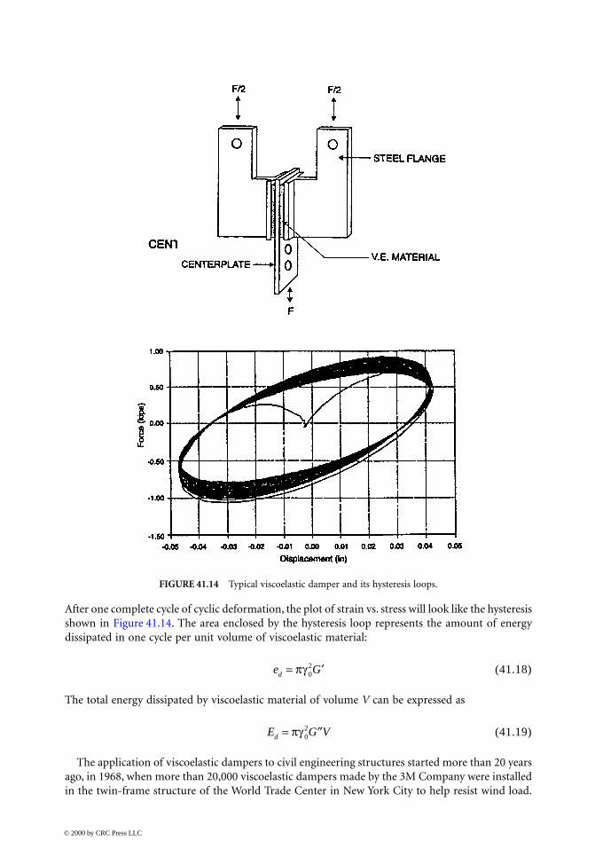
After one complete cycle of cyclic deformation, the plot of strain vs. stress will look like the hysteresisshown in Figure 41.14. The area enclosed by the hysteresis loop represents the amount of energydissipated in one cycle per unit volume of viscoelastic material:
(41.18)
The total energy dissipated by viscoelastic material of volume V can be expressed as
(41.19)
The application of viscoelastic dampers to civil engineering structures started more than 20 yearsago, in 1968, when more than 20,000 viscoelastic dampers made by the 3M Company were installedin the twin-frame structure of the World Trade Center in New York City to help resist wind load.
FIGURE 41.14 Typical viscoelastic damper and its hysteresis loops.
e Gd = ′πγ 02
E G Vd = ′′πγ 02
© 2000 by CRC Press LLC

In the late 1980s, theoretical and experimental studies were first conducted for the possibility ofapplying viscoelastic dampers for seismic applications [9,15]. Viscoelastic dampers have sincereceived increased attention from researchers and practicing engineers. Many experimental studieshave been conducted on scaled and full-scale structural models. Recently, viscoelastic dampers wereused in the seismic retrofit of several buildings, including the Santa Clara County Building in SanJose, California. In this case, viscoelastic dampers raised the equivalent damping ratio of the struc-ture to 17% of critical [16].
41.3.5 Other Types of Damping Devices
There are several other types of damping devices that have been studied and applied to seismicresistant design with varying degrees of success. These include metallic yield dampers, frictiondampers, and tuned mass dampers. Some of them are more suited for building applications andmay be of limited effectiveness to bridge structures.
Metallic Yield Damper. Controlled use of sacrificial metallic energy dissipating devices is arelatively new concept [17]. A typical device consists of one or several metallic members, usuallymade of mild steel, which are subjected to axial, bending, or torsional deformation depending onthe type of application. The choice between different types of metallic yield dampers usually dependson location, available space, connection with the structure, and force and displacement levels. Onepossible application of steel yield damper to bridge structures is to employ steel dampers in con-junction with isolation bearings. Tests have been conducted to combine a series of cantilever steeldampers with PTFE sliding isolation bearing.
Friction Damper. This type of damper utilizes the mechanism of solid friction that developsbetween sliding surfaces to dissipate energy. Several types of friction dampers have been developedfor the purpose of improving seismic response of structures. For example, studies have shown thatslip joints with friction pads placed in the braces of a building structure frame significantly reducedits seismic response. This type of braced friction dampers has been used in several buildings inCanada for improving seismic response [4,18].
Tuned Mass Damper. The basic principle behind tuned mass dampers (TMD) is the classicdynamic vibration absorber, which uses a relatively small mass attached to the main mass via arelatively small stiffness to reduce the vibration of the main mass. It can be shown that, if the periodof vibration of the small mass is tuned to be the same as that of the disturbing harmonic force, themain mass can be kept stationary. In structural applications, a tuned mass damper may be installedon the top floor to reduce the response of a tall building to wind loads [4]. Seismic application ofTMD is limited by the fact that it can only be effective in reducing vibration in one mode, usuallythe first mode.
41.4 Performance and Testing Requirements
Since seismic isolation and energy dissipation technologies are still relatively new and often theproperties used in design can only be obtained from tests, the performance and test requirementsare critical in effective applications of these devices. Testing and performance requirements, for themost part, are prescribed in project design criteria or construction specifications. Some nationallyrecognized design specifications, such as AASHO Guide Specifications for Seismic Isolation Design[19], also provide generic testing requirements.
Almost all of the testing specified for seismic isolators or energy dissipation devices require testsunder static or simple cyclic loadings only. There are, however, concerns about how well willproperties obtained from these simple loading tests correlate to behaviors under real earthquake
© 2000 by CRC Press LLC

loadings. Therefore, a major earthquake simulation testing program is under way. Sponsored bythe Federal Highway Administration and the California Department of Transportation, manufac-turers of isolation and energy dissipation devices were invited to provide their prototype productsfor testing under earthquake loadings. It is hoped that this testing program will lead to uniformguidelines for prototype and verification testing as well as design guidelines and contract specifica-tions for each of the different systems. The following is a brief discussion of some of the importanttesting and performance requirements for various systems.
41.4.1 Seismic Isolation Devices
For seismic isolation bearings, performance requirements typically specify the maximum allowablelateral displacements under seismic and nonseismic loadings, such as thermal and wind loads;horizontal deflection characteristics such as effective and maximum stiffnesses; energy dissipationcapacity, or equivalent damping ratio; vertical deflections; stability under vertical loads; etc. Forexample, the AASHTO Guide Specifications for Seismic Isolation Design requires that the design andanalysis of isolation system prescribed be based on prototype tests and a series of verification testsas briefly described in the following:
Prototype Tests:
I. Prototype tests need to be performed on two full-size specimens. These tests are required foreach type and size similar to that used in the design.
II. For each cycle of tests, the force–deflection and hysteresis behavior of the specimen need tobe recorded.
III. Under a vertical load similar to the typical average design dead load, the specimen need tobe tested forA. Twenty cycles of lateral loads corresponding to the maximum nonseismic loads;B. Three cycles of lateral loading at displacements equaling 25, 50, 75, 100, and 125% of the
total design displacement;C. Not less than 10 full cycles of loading at the total design displacement and a vertical load
similar to dead load.IV. The stability of the vertical load-carrying element need to be demonstrated by one full cycle
of displacement equaling 1.5 times the total design displacement under dead load plus orminus vertical load due to seismic effect.
System Characteristics Tests:
I. The force–deflection characteristics need to be based on cyclic test results.
II. The effective stiffness of an isolator needs to be calculated for each cycle of loading as
(41.20)
where Fp and Fn are the maximum positive and negative forces, respectively, and arethe maximum positive and negative displacements, respectively.
III. The equivalent viscous damping ratio ξ of the isolation system needs to be calculated as
(41.21)
kF Fp n
p neff =
−−∆ ∆
∆ ∆p n and
ξπ
=
∑Total Area
42
2kd
© 2000 by CRC Press LLC
where Total Area shall be taken as the sum of areas of the hysteresis loops of all isolators; thesummation in the denominator represents the total strain energy in the isolation system.
In order for a specimen to be considered acceptable, the results of the tests should show positiveincremental force-carrying capability, less than a specified amount of variation in effective stiffnessbetween specimens and between testing cycles for any given specimen. The effective damping ratioalso needs to be within certain range [19].
41.4.2 Testing of Energy Dissipation Devices
As for energy dissipation devices, there have not been any codified testing requirements published.The Federal Emergency Management Agency 1994 NEHRP Recommended Provisions for SeismicRegulation for New Buildings contains an appendix that addresses the use of energy dissipationsystems and testing requirements [20]. There are also project-specific testing requirements andproposed testing standards by various damper manufacturers.
Generally speaking, testing is needed to obtain appropriate device parameters for design use.These parameters include the maximum force output, stroke distance, stiffness, and energy dissi-pation capability. In the case of viscous dampers, these are tested in terms of damping constant C,exponential constant, maximum damping force, etc. Most of the existing testing requirements areproject specific. For example, the technical requirements for viscous dampers to be used in theretrofit of the Golden Gate Bridge specify a series of tests to be carried out on model dampers[13,21]. Prototype tests were considered to be impractical because of the limitation of availabletesting facilities. These tests include cyclic testing of model dampers to verify their constitutive lawand longevity of seals and a drop test of model and prototype dampers to help relate cyclic testingto the behavior of the actual dampers. Because the tests will be on model dampers, some calculationswill be required to extrapolate the behavior of the prototype dampers.
41.5 Design Guidelines and Design Examples
In the United States, design of seismic isolation for bridges is governed by the Guide Specificationsfor Seismic Isolation Design (hereafter known as “Guide Specifications”) published by AASHTO in1992. Specifications for the design of energy dissipation devices have not been systematically devel-oped, while recommended guidelines do exist for building-type applications.
In this section, design procedure for seismic isolation design and a design example will bepresented mainly based on the AASHTO Guide Specifications. As for the design of supplementalenergy dissipation, an attempt will be made to summarize some of the guidelines for building-typestructures and their applicability to bridge applications.
41.5.1 Seismic Isolation Design Specifications and Examples
The AASHTO Guide Specifications were written as a supplement to the AASHTO Standard Speci-fications for the Seismic Design of Highway Bridges [22] (hereafter known as “Standard Specifica-tions”). Therefore, the seismic performance categories and site coefficients are identical to thosespecified in the Standard Specifications. The response modification factors are the same as in theStandard Specifications except that a reduced R factor of 1.5 is permitted for essentially elastic designwhen the design intent of seismic isolation is to eliminate or significantly reduce damage to thesubstructure.
General RequirementsThere are two interrelated parts in designing seismic isolation devices for bridge applications. Firstof all, isolation bearings must be designed for all nonseismic loads just like any other bearing devices.For example, for lead core rubber isolation bearings, both the minimum plan size and the thicknessof individual rubber layers are determined by the vertical load requirement. The minimum isolator
© 2000 by CRC Press LLC

height is controlled by twice the displacement due to combined nonseismic loads. The minimumdiameter of the lead core is determined by the requirement to maintain elastic response undercombined wind, brake, and centrifugal forces. Similar requirements can also be applied to othertypes of isolators. In addition to the above requirements, the second part of seismic isolation designis to satisfy seismic safety requirements. The bearing must be able to support safely the verticalloads at seismic displacement. This second part is accomplished through the analysis and designprocedures described below.
Methods of AnalysisThe Guide Specifications allow treatment of energy dissipation in isolators as equivalent viscousdamping and stiffness of isolated systems as effective linear stiffness. This permits both the singleand multimodal methods of analysis to be used for seismic isolation design. Exceptions to this areisolated systems with damping ratios greater than 30% and sliding type of isolators without a self-centering mechanism. Nonlinear time history analysis is required for these cases.
Single-Mode Spectral AnalysisIn this procedure, equivalent static force is given by the product of the elastic seismic force coefficient
and dead load W of the superstructure supported by isolation bearings, i.e.,
(41.22)
(41.23)
(41.24)
where
= the sum of the effective linear stiffness of all bearings supporting the superstructure
= displacement across the isolation bearings
A = the acceleration coefficient
B = the damping coefficient given in Table 41.3
= the period of vibration
The equivalent static force must be applied independently to the two orthogonal axes andcombined per the procedure of the standard specifications. The effective linear stiffness should becalculated at the design displacement.
TABLE 41.3 Damping Coefficient B
Damping Ratio (ξ) ≤ 2% 5% 10% 20% 30%
B 0.8 1.0 1.2 1.5 1.7
Source: AASHTO, Guide Specification for Seismic IsolationDesign, Washington, D.C., 1991. With permission.
Cs
F C Ws=
Ck d
Ws
i=×∑ eff
CAS
T Bsi
e
=
keff∑d
AS T
Bii e=
10
TW
g ke =
∑ eff
© 2000 by CRC Press LLC
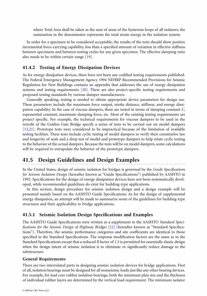
Response Spectrum AnalysisThis procedure is the same as specified in the Standard Specifications using the 5% damping groundmotion response spectra with the following modifications:
1. The isolation bearings are represented by their effective stiffness values.2. The response spectrum is modified to include the effect of higher damping of the isolated
system. This results in a reduction of the response spectra values for the isolated modes. Forall the other modes, the 5% damping response spectra should be used.
A typical modified response spectrum is shown in Figure 41.15.
Time History AnalysisAs mentioned earlier, time history analysis is required for isolation systems with high damping ratio(>30%) or non-self-centering isolation systems. The isolation systems need to be modeled usingnonlinear force–deflection characteristics of the isolator obtained from tests. Pairs of ground accel-eration time history recorded from different events should be selected. These acceleration timehistories should be frequency-scaled to match closely the appropriate response spectra for the site.Recommended methods for scaling are also given in the Guide Specifications. At least three pairsof time histories are required by the code. Each pair should be simultaneously applied to the model.The maximum response should be used for the design.
Design Displacement and Design ForceIt is necessary to know and limit the maximum displacement of an isolation system resulting fromseismic loads and nonseismic service loads for providing adequate clearance and design structuralelements. The Guide Specifications require that the total design displacement be the greater of 50%of the elastomer shear strain in an elastomeric bearing system and the maximum displacementresulted from the combination of loads specified in the Standard Specifications.
Design forces for a seismically isolated bridge are obtained using the same load combinations asgiven for a conventionally designed bridge. Connection between superstructure and substructureshall be designed using force . Columns and piers should be designed for the maximum
FIGURE 41.15 Modified input response spectrum.
F k di= eff
© 2000 by CRC Press LLC

force that may be developed in the isolators. The foundation design force needs not to exceed theelastic force nor the force resulted from plastic hinging of the column.
Other RequirementsIt is important for an isolation system to provide adequate rigidity to resist frequently occurringwind, thermal, and braking loads. The appropriate allowed lateral displacement under nonseismicloads is left for the design engineer to decide. On the lateral restoring force, the Guide Specificationsrequire a restoring force that is 0.25W greater than the lateral force at 50% of the design displace-ment. For systems not configured to provide a restoring force, more stringent vertical stabilityrequirements have to be met.
The Guide Specifications recognize the importance of vertical stability of an isolated system byrequiring a factor of safety not less than three for vertical loads in its undeformed state. A systemshould also be stable under the dead load plus or minus the vertical load due to seismic load at ahorizontal displacement of 1.5 times the total design displacement. For systems without a lateralrestoring force, this requirement is increased to three times the total design displacement.
Guidelines for Choosing Seismic IsolationWhat the Guide Specifications do not cover are the conditions under which the application ofseismic isolation becomes necessary or most effective. Still, some general guidelines can be drawnfrom various literatures and experiences as summarized below.
One factor that favors the use of seismic isolation is the level of acceptable damage to the bridge.Bridges at critical strategic locations need to stay open to traffic following a seismic event with nodamage or minor damages that can be quickly repaired. This means that the bridges are to beessentially designed elastically. The substructure pier and foundation cost could become prohibitiveif using conventional design. The use of seismic isolation may be an economic solution for thesebridges, if not the only solution. This may apply to both new bridge design and seismic upgrade ofexisting bridges.
Sometimes, it is desirable to reduce the force transferred to the superstructure, as in the case ofseismic retrofit design of the Benicia–Martinez Bridge, in the San Francisco Bay, where isolationbearings were used to limit the forces in the superstructure truss members [11].
Another factor to consider is the site topography of the bridge. Irregular terrain may result inhighly irregular structure configurations with significant pier height differences. This will result inuneven seismic force distributions among the piers and hence concentrated ductility demands. Useof seismic isolation bearings will make the effective stiffness and expected displacement of pierscloser to each other resulting in a more even force distribution [23].
For seismic upgrading of existing bridges, isolation bearings can be an effective solution forunderstrength piers, insufficient girder support length, and inadequate bearings.
In some cases, there may not be an immediate saving from the use of seismic isolation over aconventional design. Considerations need to be given to a life-cycle cost comparison because theuse of isolation bearings generally means much less damages, and hence lower repair costs in thelong run.
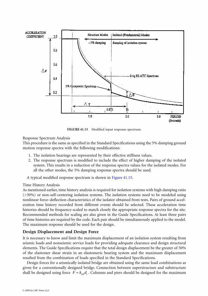
Seismic Isolation Design ExampleAs an example, a three-span continuous concrete box-girder bridge structure, shown in Figure 41.16,will be used here to demonstrate the seismic isolation design procedure. Material and structureproperties are also given in Figure 41.16. The bridge is assumed to be in a high seismic area withan acceleration coefficient A of 0.40, soil profile Type II, S = 1.2. For simplicity, let us use the singlemode spectral analysis method for the analysis of this bridge. Assuming that the isolation bearingswill be designed to provide an equivalent viscous damping of 20%, with a damping coefficient, B,of 1.5. The geometry and section properties of the bridge are taken from the worked example inthe Standard Specifications with some modifications.
© 2000 by CRC Press LLC
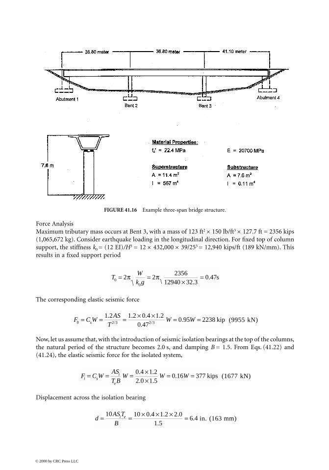
Force AnalysisMaximum tributary mass occurs at Bent 3, with a mass of 123 ft2 × 150 lb/ft3 × 127.7 ft = 2356 kips(1,065,672 kg). Consider earthquake loading in the longitudinal direction. For fixed top of columnsupport, the stiffness k0 = (12 EI)/H3 = 12 × 432,000 × 39/253 = 12,940 kips/ft (189 kN/mm). Thisresults in a fixed support period
The corresponding elastic seismic force
(9955 kN)
Now, let us assume that, with the introduction of seismic isolation bearings at the top of the columns,the natural period of the structure becomes 2.0 s, and damping B = 1.5. From Eqs. (41.22) and(41.24), the elastic seismic force for the isolated system,
(1677 kN)
Displacement across the isolation bearing
in. (163 mm)
FIGURE 41.16 Example three-span bridge structure.
TWk g0
0
2 22356
12940 32 30 47= =
×=π π
.. s
F C WAS
TW Ws0 2 3 2 3
1 2 1 2 0 4 1 20 47
0 95 2238= = = × × = =. . . ..
./ / kip
F C WAS
T BW W Wi s
i
e
= = = ××
= =0 4 1 22 0 1 5
0 16 377. .. .
. kips
dAS T
Bi e= = × × × =
10 10 0 4 1 2 2 01 5
6 4. . .
..
© 2000 by CRC Press LLC

Table 41.4 examines the effect of isolation period on the elastic seismic force. For an isolated periodof 0.5 s, which is approximately the same as the fixed support structure, the 30% reduction in elasticseismic force represents basically the effect of the added damping of the isolation system.
Isolation Bearing DesignAssume that four elastomeric (lead core rubber) bearings are used at each bent for this structure.Vertical local due to gravity load is P = 2356/4 = 589 kips (2620 kN). We will design the bearingssuch that the isolated system will have a period of 2.5 s.
and
where T is the total thickness of the elastomer. We have
kip/in. (0.54 kN/mm)
Assuming a shear modulus G = 145 psi (1.0 MPa) and bearing thickness of T = 18 in. (457 mm)with thickness of each layer ti equaling 0.5 in . This gives a bearing area A = 380 in2
(245,070 mm2).Hence, a plan dimension of 19.5 × 19.5 in. (495 × 495 mm).
Check shape factor:
OK
Shear strain in the elastomer is the critical characteristic for the design of elastomeric bearings.Three shear strain components make up the total shear strain; these are shear strains due to
vertical compression, rotation, and horizontal shear deformation. In the Guide Specifications, theshear strain due to compression by vertical load is given by
TABLE 41.4 Seismic Isolation Design Example Results
Te (s) 0.5 1.0 1.5 2.0 2.5 3.0
keff (kips/in) 306.48 76.62 34.05 19.16 12.26 8.51
(kN/mm) (53.67) (13.42) (5.96) (3.35) (2.15) (1.49)d (in.) 1.60 3.20 4.80 6.40 8.00 9.60
(mm) (40.64) (81.28) (121.92) (162.56) (203.20) (243.84)Cs 0.64 0.32 0.21 0.16 0.13 0.11
Fi (kip) 1507.84 753.92 502.61 376.96 301.57 251.31
(kN) (6706.87) (3353.44) (2235.62) (1676.72) (1341.37) (1117.81)
TW
g ke =
∑ eff
kGATeff =
4
GAT
= 3 06.
Sab
t (a b)i
=+
= ×× +2
19 5 19 52 0 5 19 5 19 5
. .. ( . . )
γ cr
SWA G kS
=+
32 1 2 2( )
© 2000 by CRC Press LLC

where Ar = 19.5 × (19.5 in. 8.0 in.) = 224.3 in.2 is the reduced bearing area representing the effectivebearing area when undergoing horizontal displacement. In this case horizontal displacement is 8.0in. For the purpose of presenting a simple example, an approximation of the previous expressioncan be used:
Shear strain due to horizontal shear deformation
and shear strain due to rotation
The Guide Specifications require that the sum of all three shear strain components be less than50% of the ultimate shear strain of the elatomer, or 5.0, whichever is smaller. In this example, thesum of all three shear strain components equals 2.50 < 5.0.
In summary, we have designed four elastomeric bearings at each bent with a plan dimension of19.5 × 19.5 in. (495 × 495 mm) and 36 layers of 0.5 in. elastomer with G = 145 psi (1 MPa).
41.5.2 Guidelines for Energy Dissipation Devices Design
There are no published design guidelines or specifications for application of damping devices tobridge structures. Several recommended guidelines for application of dampers to building structureshave been in development over the last few years [20,24,25]. It is hoped that a brief summary ofthese developments will be beneficial to bridge engineers.
General RequirementsThe primary function of an energy dissipation device in a structure is to dissipate earthquake-induced energy. No special protection against structural or nonstructural damage is sought orimplied by the use of energy dissipation systems.
Passive energy dissipation systems are classified as displacement-dependent, velocity-dependent,or other. The fluid damper and viscoelastic damper as discussed in Section 41.3 are examples of thevelocity-dependent energy dissipation system. Friction dampers are displacement-dependent. Dif-ferent models need to be used for different classes of energy dissipation systems. In addition toincreasing the energy dissipation capacity of a structure, energy dissipation systems may also alterthe structure stiffness. Both damping and stiffness effects need to be considered in designing energydissipation systems.
Analysis ProceduresThe use of linear analysis procedures is limited to viscous and viscoelastic energy dissipation systems.If nonlinear response is likely or hysteretic or other energy dissipaters are to be analyzed anddesigned, nonlinear analysis procedure must be followed. We will limit our discussion to linearanalysis procedure.
Similar to the analysis of seismic isolation systems, linear analysis procedures include threemethods: linear static, linear response spectrum, and linear time history analysis.
γ σc GS
= = ×× ×
=589 1000224 3 145 9 75
1 85. .
.
γ s
dT
= = =818
0 44in.in.
.
γ θr
i
Bt T
= = ×× ×
=2 2
219 5 0 012 0 5 18
0 21. .
..
© 2000 by CRC Press LLC
When using the linear static analysis method, one needs to make sure that the structure, exclusiveof the dampers, remains elastic, that the combined structure damper system is regular, and thateffective damping does not exceed 30%. The earthquake-induced displacements are reduced due toequivalent viscous damping provided by energy dissipation devices. This results in reduced baseshears in the building structure.
The acceptability of the damped structure system should be demonstrated by calculations suchthat the sum of gravity and seismic loads at each section in each member is less than the memberor component capacity.
The linear dynamic response spectrum procedure is used for more complex structure systems,where structures are modeled as MDOF systems. Modal response quantities are reduced based onthe amount of equivalent modal damping provided by supplemental damping devices.
Detailed System RequirementsOther factors that need to be considered in designing supplemental damping devices for seismicapplications are environmental conditions, nonseismic lateral loads, maintenance and inspection,and manufacturing quality control.
Energy dissipation devices need to be designed with consideration given to environmental con-ditions including aging effect, creep, and ambient temperature. Structures incorporated with energy-dissipating devices that are susceptible to failure due to low-cycle fatigue should resist the prescribeddesign wind forces in the elastic range to avoid premature failure. Unlike conventional constructionmaterials that are inspected on an infrequent basis, some energy dissipation hardware will requireregular inspections. It is, therefore, important to make these devices easily accessible for routineinspection and testing or even replacement.
41.6 Recent Developments and Applications
The last few years have seen significantly increased interest in the application of seismic isolationand supplemental damping devices. Many design and application experiences have been published.A shift from safety-only-based seismic design philosophy to a safety-and-performance-based phi-losophy has put more emphasis on limiting structural damage by controlling structural seismicresponse. Therefore, seismic isolation and energy dissipation have become more and more attractivealternatives to traditional design methods. Design standards are getting updated with the newdevelopment both in theory and technology. While the Guide Specifications referenced in thischapter addresses mainly elastomeric isolation bearing, new design specifications under develop-ment and review will include provisions for more types of isolation devices [26].
41.6.1 Practical Applications of Seismic Isolation
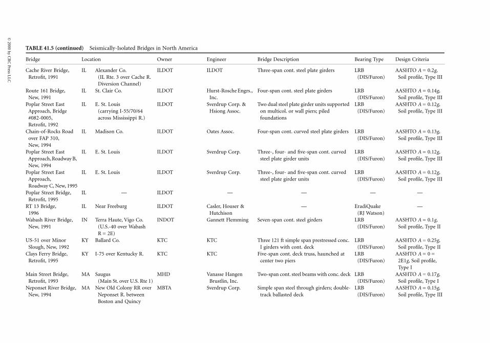
Table 41.5 lists bridges in North America that have isolation bearings installed. This list, as long as itlooks, is still not complete. By some estimates, there have been several hundred isolated bridges world-wide and the number is growing. The Earthquake Engineering Research Center (EERC) at the Universityof California, Berkeley keeps a complete listing of the bridges with isolation and energy dissipationdevices. Table 41.5 is based on information available from the EERC Internet Web site.
41.6.2 Applications of Energy Dissipation Devices to Bridges
Compared with seismic isolation devices, the application of energy dissipation devices as an independentperformance improvement measure is lagging behind. This is due, in part, to the lack of code devel-opment and limited applicability of the energy dissipation devices to bridge-type structures as discussedearlier. Table 41.6 gives a list of bridge structures with supplemental damping devices against seismicand wind loads. This table is, again, based on information available from the EERC Internet Web site.
© 2000 by CRC Press LLC

© 2000 by C
RC
Press LL
C
TABL
Bridge Bearing Type Design Criteria
Dog RNew,
te girders LRB (DIS/Furon)
AASHTO Category A
Deas SRetro
aunched steel LRB (DIS/Furon)
AASHTO A = 0.2g, Soil profile, Type III
BurrarSpan
deck trusses; ough truss
LRB (DIS/Furon)
AASHTO A = 0.21g, Soil profile, Type I
QueenBridg
pan cont. ers; two-girder
LRB (DIS/Furon)
AASHTO A = 0.2g, Soil profile, Type I
RoberNew,
ved steel plate LRB AASHTO A = 0.26g, Soil profile, Type II
GranvRetro
FIP —
White1997
FPS —
Sierra Retro
ders, trans. steel LRB (DIS/Furon)
Caltrans A = 0.6g, 0 to 10 ft alluvium
Santa ARetro
through trusses, spans
LRB (DIS/Furon)
ATC A = 0.4g, Soil profile, Type II
Eel RivRetro
uss simple spans LRB (DIS/Furon)
Caltrans A = 0.5g, < 150 ft alluvium
Main YAccesRetro
el through plate , conc. deck
LRB (DIS/Furon)
Caltrans A = 0.5g, 10 to 80 ft alluvium
All-AmBridgRetro
eplacing former LRB (DIS/Furon)
Caltrans A = 0.6g, >150 ft alluvium
CarlsoBridgNew,
c. box girder LRB (DIS/Furon)
Caltrans A = 0.7g, 80 to 150 ft alluvium
OlympSeparNew,
girders LRB (DIS/Furon)
Caltrans A = 0.6g, 10 to 80 ft alluvium
E 41.5 Seismically-Isolated Bridges in North America
Location Owner Engineer Bridge Description
iver Bridge, 1992
AL Mobile Co. Alabama Hwy = 2E Dept.
Alabama Hwy. Dept. Three-span cont. steel pla
lough Bridge, fit, 1990
BC Richmond (Hwy. 99 over Deas Slough),
British Columbia Ministry of Trans. & Hwys.
PBK Eng. Ltd. Three-span cont. riveted hplate girders
d Bridge Main s, Retrofit, 1993
BC Vancouver (Burrard St. over False Cr.),
City of Vancouver Buckland & Taylor Ltd.
Side spans are simple spancenter span is a Pratt thr
sborough e, Retrofit, 1994
BC New Westminster (over N. arm of Fraser River),
British Columbia Ministry of Trans. & Hwys.
Sandwell Eng. High-level bridge, three-shaunched steel plate girdsystem with floor beams
ts Park Overhead, 1996
BC Vancouver (Deltaport Extension over BC Rail tracks)
Vancouver Port Corp.
Buckland & Taylor Ltd.
Five-span continuous curgirders, three girder lines
ille Bridge, fit, 1996
BC Vancouver, Canada — — —
River Bridge, (est.)
YU Yukon, Canada Yukon Trans. Services
— —
Pt. Overhead, fit, 1985
CA S. San Francisco (U.S. 101 over S.P. Railroad)
Caltrans Caltrans Longitudinal steel plate girplate bent cap girders
na River Bridge, fit, 1986
CA Riverside MWDSC Lindvall, Richter & Assoc.
Three 180 ft simple span 10 steel girder approach
er Bridge, fit, 1987
CA Rio Dell (U.S. 101 over Eel River)
Caltrans Caltrans Two 300 ft steel through tr
ard Vehicle s Bridge, fit, 1987
CA Long Beach (former RR bridge over Long Beach Freeway)
LACMTA W. Koo & Assoc., Inc. Two 128 ft simple span stegirders, steel floor beams
erican Canal e, fit, 1988
CA Winterhaven, Imperial Co. (I-8 over All-American Canal)
Caltrans Caltrans Cont. steel plate girders (rsteel deck trusses)
n Boulevard e, 1992
CA Richmond (part of 23rd St. Grade Separation Project)
City of Richmond A-N West, Inc. Simple span multicell con
ic Boulevard ation,
1993
CA Walnut Creek (part of the 24/680 Reconstruction Project)
Caltrans Caltrans Four-span cont. steel plate

© 2000 by C
RC
Press LL
C
ct, R.C. box its
LRB (DIS/Furon)
Caltrans A = 0.5g, 10 to 80 ft alluvium
c. box girder LRB (DIS/Furon)
Caltrans A = 0.53g, 80 to 150 ft alluvium
e girders LRB (DIS/Furon)
Caltrans A = 0.53g, 0 to 10 ft alluvium
with tapered LRB Caltrans A = 0.6g, 0 to 10 ft alluvium
d by short LRB (DIS) Caltrans A = 0.5g, 10 to 80 ft alluvium
Eradiquake (RJ Watson)
—
LRB (Skellerup) —
LRB (Skellerup) —
FPS (EPS) —
s concrete FPS (EPS) Caltrans A = 0.5g,10 to 80 ft alluvium
LRB —
FPS (EPS) —
HDR (not selected)
—
units of 3, 4, LRB (DIS/Furon)
AASHTO A = 0.16g, Soil profile, Type II
irders LRB (DIS/Furon)
AASHTO A = 0.15g, Soil profile, Type III
EradiQuake(RJ Watson)
—
irders LRB (DIS/Furon)
AASHTO A = 0.2g, Soil profile, Type III
TABLE 41.5 (continued) Seismically-Isolated Bridges in North America
Bridge Location Owner Engineer Bridge Description Bearing Type Design Criteria
Alemany Interchange, Retrofit, 1994
CA I-280/U.S. 101 Interchange, San Francisco
Caltrans PBQD Single and double deck viadugirders and cols., 7-cont. un
Route 242/I-680 Separation, Retrofit, 1994
CA Concord (Rte. 242 SB over I-680)
Caltrans HDR Eng., Inc. 8 ft-deep cont. prestressed con
Bayshore Boulevard Overcrossing, Retrofit, 1994
CA San Francisco (Bayshore Blvd. over U.S. 101)
Caltrans Winzler and Kelly Continuous welded steel plat
1st Street over Figuero, Retrofit, 1995
CA Los Angeles City of Los Angeles Kercheval Engineers Continuous steel plate girdersend spans
Colfax Avenue over L.A. River, Retrofit, 1995
CA Los Angeles City of Los Angeles Kercheval Engineers Deck truss center span flankesteel beam spans
Colfax Avenue over L.A. River, Retrofit, 1995
CA Los Angeles City of Los Angeles — —
3-Mile Slough, Retrofit, 1997 (est.)
CA — Caltrans — —
Rio Vista, Retrofit, 1997 (est.)
CA — Caltrans — —
Rio Mondo Bridge, Retrofit, 1997 (est.)
CA — Caltrans — —
American River Bridge City of Folsom, New, 1997 (est.)
CA Folsom City of Folsom -HDR Ten-span, 2-frame continuoubox girder bridge
GGB North Viaduct, Retrofit, 1998 (est.)
CA — GGBHTD — —
Benicia–Martinez Bridge Retrofit, 1998 (est.)
CA — Caltrans — —
Coronado Bridge, Retrofit, 1998 (est.)
CA — Caltrans — —
Saugatuck River Bridge, Retrofit, 1994
CT Westport (I-95 over Saugatuck R.)
ConnDOT H.W. Lochner, Inc. Three cont. steel plate girder and 3 spans
Lake Saltonstall Bridge, New, 1995
CT E. Haven & Branford (I-95 over Lake Saltonstall)
ConnDOT Steinman Boynton Gronquist & Birdsall
Seven-span cont. steel plate g
RT 15 Viaduct, 1996
CT Hamden ConnDOT Boswell Engineers —
Sexton Creek Bridge, New, 1990
IL Alexander Co. (IL Rte. 3 over Sexton Creek)
ILDOT ILDOT Three-span cont. steel plate g
© 2000 by C
RC
Press LL
C
CacheRetro
te girders LRB (DIS/Furon)
AASHTO A = 0.2g, Soil profile, Type III
Route New,
girders LRB (DIS/Furon)
AASHTO A = 0.14g, Soil profile, Type III
PoplarAppr#082Retro
units supported s; piled
LRB (DIS/Furon)
AASHTO A = 0.12g, Soil profile, Type III
Chainover New,
eel plate girders LRB (DIS/Furon)
AASHTO A = 0.13g, Soil profile, Type III
PoplarApprNew,
n cont. curved LRB (DIS/Furon)
AASHTO A = 0.12g, Soil profile, Type III
PoplarApprRoad
n cont. curved LRB (DIS/Furon)
AASHTO A = 0.12g, Soil profile, Type III
PoplarRetro
— —
RT 131996
EradiQuake (RJ Watson)
—
WabasNew,
ers LRB (DIS/Furon)
AASHTO A = 0.1g, Soil profile, Type II
US-51Sloug
restressed conc. LRB (DIS/Furon)
AASHTO A = 0.25g, Soil profile, Type II
Clays FRetro
, haunched at LRB (DIS/Furon)
AASHTO A = 0 = 2E1g, Soil profile, Type I
Main SRetro
s with conc. deck LRB (DIS/Furon)
AASHTO A = 0.17g, Soil profile, Type I
NeponNew,
girders; double- LRB (DIS/Furon)
AASHTO A = 0.15g, Soil profile, Type III
TABL
Bridge Bearing Type Design Criteria
River Bridge, fit, 1991
IL Alexander Co. (IL Rte. 3 over Cache R. Diversion Channel)
ILDOT ILDOT Three-span cont. steel pla
161 Bridge, 1991
IL St. Clair Co. ILDOT Hurst-Rosche Engrs., Inc.
Four-span cont. steel plate
Street East oach, Bridge -0005, fit, 1992
IL E. St. Louis (carrying I-55/70/64 across Mississippi R.)
ILDOT Sverdrup Corp. & Hsiong Assoc.
Two dual steel plate girderon multicol. or wall pierfoundations
-of-Rocks Road FAP 310, 1994
IL Madison Co. ILDOT Oates Assoc. Four-span cont. curved st
Street East oach, Roadway B, 1994
IL E. St. Louis ILDOT Sverdrup Corp. Three-, four- and five-spasteel plate girder units
Street East oach, way C, New, 1995
IL E. St. Louis ILDOT Sverdrup Corp. Three-, four- and five-spasteel plate girder units
Street Bridge, fit, 1995
IL — ILDOT — —
Bridge, IL Near Freeburg ILDOT Casler, Houser & Hutchison
—
h River Bridge, 1991
IN Terra Haute, Vigo Co. (U.S.-40 over Wabash R = 2E)
INDOT Gannett Flemming Seven-span cont. steel gird
over Minor h, New, 1992
KY Ballard Co. KTC KTC Three 121 ft simple span pI girders with cont. deck
erry Bridge, fit, 1995
KY I-75 over Kentucky R. KTC KTC Five-span cont. deck trusscenter two piers
treet Bridge, fit, 1993
MA Saugus (Main St. over U.S. Rte 1)
MHD Vanasse Hangen Brustlin, Inc.
Two-span cont. steel beam
set River Bridge, 1994
MA New Old Colony RR over Neponset R. between Boston and Quincy
MBTA Sverdrup Corp. Simple span steel throughtrack ballasted deck
E 41.5 (continued) Seismically-Isolated Bridges in North America
Location Owner Engineer Bridge Description

© 2000 by C
RC
Press LL
C
hree trapez. ont. unit with x girders
LRB (DIS/Furon)
AASHTO A = 0.17g, Soil profile, Type III
girders. LRB (DIS) AASHTO A = 0.18g, Soil profile, Type III
nuous center s.
LRB (DIS) AASHTO A = 0.17g, Soil profile, Type II
nuous center s.
LRB (DIS) AASHTO A = 0.17g, Soil profile, Type I
ams LRB (DIS) AASHTO A = 0.17g, Soil profile, Type III
beams with LRB (DIS) AASHTO A = 0.17g, Soil profile, Type I
EradiQuake (RJ Watson)
—
EradiQuake (RJ Watson)
—
EradiQuake (RJ Watson)
—
EradiQuake (RJ Watson)
—
HDR (SEP, formerly Furon)
—
LRB, NRB (SEP, formerly Furon)
—
er flanked by LRB (DIS/Furon)
AASHTO A = 0.1g, Soil profile, Type I
nc. box girder LRB (DIS/Furon)
AASHTO A = 0.1g, Soil profile, Type I
conc. box LRB (DIS/Furon)
AASHTO A = 0.1g, Soil profile, Type I
, cont. ; cont. curved
LRB (DIS/Furon)
AASHTO A = 0.1g, Soil profile, Type I
TABLE 41.5 (continued) Seismically-Isolated Bridges in North America
Bridge Location Owner Engineer Bridge Description Bearing Type Design Criteria
South Boston Bypass Viaduct, New, 1994
MA S. Boston MHDCATP DRC Consult., Inc. Conc. deck supported with tsteel box girders; 10-span ctwo curved trapez. steel bo
South Station Connector, New, 1994
MA Boston MBTA HNTB Curved, trapezoidal steel ox
North Street Bridge No. K-26, Retrofit, 1995
MA Grafton (North Street over Turnpike)
MTA The Maguire Group Inc.
Steel beams, two-span contiunit flanked by simple span
Old Westborough Road Bridge, Retrofit, 1995
MA Grafton MTA The Maguire Group Inc.
Steel beams, two-span contiunit flanked by simple span
Summer Street Bridge, Retrofit, 1995
MA Boston (over Fort Point Channel)
MHD STV Group Six-span continuous steel be
West Street over I-93, Retrofit, 1995
MA Wilmington MHD Vanesse Hangen Brustlin,
Four-span continuous steel concrete deck.
Park Hill over Mass. Pike (I-90), 1995
MA Millbury Mass Turnpike Purcell Assoc./HNTB —
RT 6 Swing Bridge,1995
MA New Bedford MHD Lichtenstein —
Mass Pike (I-90) over Fuller & North Sts., 1996
MA Ludlow Mass Turnpike Maguire/HNTB —
Endicott Street over RT 128 (I-95), 1996
MA Danvers MHD Anderson Nichols —
I-93 Mass Ave. Interchange, 1996
MA S. Boston (Central Artery (I-93)/Tunnel (I-90))
MHD Ammann & Whitney —
Holyoke/South Hadley Bridge, 1996
MA South Hadley, MA (Reconstruct over Conn. River & Canal St.)
MHD Bayside Eng. Assoc., Inc.
—
NB I-170 Bridge, New, 1991
MO St. Louis (Metrolink Light Rail over NB I-170)
BSDA Booker Assoc., Inc. and Horner & Shifrin
Two-span cont. steel box girdshort span steel box girders
Ramp 26 Bridge, New, 1991
MO St. Louis (Metrolink Light Rail over Ramp 26)
BSDA Booker Assoc., Inc. and Horner & Shifrin
Four-span cont. haunched co
Springdale Bridge, New, 1991
MO St. Louis (Metrolink Light Rail over Springdale Rd.)
BSDA Booker Assoc., Inc. and Horner & Shifrin
Three-span cont. haunched girder
SB I-170/EB I-70 Bridge, New, 1991
MO St. Louis (Metrolink Light Rail over SB I-170/EB I-70)
BSDA Booker Assoc., Inc. and Horner & Shifrin
Simple span steel box girderhaunched conc. box girdersteel box girder

© 2000 by C
RC
Press LL
C
mple spans LRB (DIS/Furon)
AASHTO A = 0.18g, Soil profile, Type II
spans LRB (DIS/Furon)
AASHTO A = 0.18g, Soil profile, Type I
nits of five and LRB (DIS/Furon)
AASHTO A = 0.18g, Soil profile, Type II
nits of three, ns
LRB (Furon) AASHTO A = 0.18g, Soil profile, Type II
ans LRB (DIS) AASHTO A = 0.18g, Soil profile, Type I
eel beams LRB (DIS) AASHTO A = 0.18g, Soil profile, Type II
LRB (SEP, formerly Furon)
—
LRB, NRB (SEP) —
LRB NRB (SEP, formerly Furon)
—
eel plate girders LRB (DIS/Furon)
AASHTO A = 0 = 2E37g, Soil profile, Type I
am structures LRB (DIS/Furon)
AASHTO A = 0.19g, Soil profile, Type III
nc. deck LRB (DIS/Furon)
AASHTO A = 0.19g, Soil profile, Type III
ted steel plate ted steel plate
LRB (DIS/Furon)
AASHTO A = 0.19g, Soil profile, Type II
TABLE 41.5 (continued) Seismically-Isolated Bridges in North America
Bridge Location Owner Engineer Bridge Description Bearing Type Design Criteria
Conrail Newark Branch Overpass E106.57, Retrofit, 1994
NJ Newark (NJ Tpk. NB over Conrail-Newark Branch)
NJTPA Gannett-Fleming, Inc.
Steel plate girders, four si
Wilson Avenue Overpass E105.79SO, Retrofit, 1994
NJ Newark (NJ Tpk. Relocated E-NSO & W-NSO over Wilson Ave.)
NJTPA Frederick R. Harris, Inc.
Steel beams, three simple
Relocated E-NSO Overpass W106.26A, New, 1994
NJ Newark (NJ Tpk. E-NSO ramp)
NJTPA Frederick R = 2E Harris, Inc.
Steel plate girders, cont. ufour spans
Berry’s Creek Bridge, Retrofit, 1995
NJ E. Rutherford (Rte. 3 over Berry’s Cr. and NJ Transit)
NJDOT Goodkind and O’Dea, Inc.
Cont. steel plate girders; ufour, three, and three spa
Conrail Newark Branch Overpass W106.57, Retrofit, 1995
NJ Newark (NJ Tpk. Rd. NSW over Conrail-Newark Branch & access rd.)
NJTPA Frederick R. Harris, Inc.
Steel beams, six simple sp
Norton House Bridge, Retrofit, 1996
NJ Pompton Lakes Borough and Wayne Township, Passaic County
NJDOT A.G. Lichtenstein & Assoc.,
Three-span continuous st
Tacony-Palmyra Approaches, 1996
NJ Palmyra, NJ Burlington County Bridge Comm.
Steinman/Parsons Engineers
—
Rt. 4 over Kinderkamack Rd., 1996
NJ Hackensack, NJ (Widening & Bridge Rehabilitation)
NJDOT A.G. Lichtenstein & Assoc.
—
Baldwin Street/Highland Avenue, 1996
NJ Glen Ridge, NJ Bridge over Conrail
NJDOT A.G. Lichtenstein & Asso.
—
I-80 Bridges B764E & W, Retrofit, 1992
NV Verdi, Washoe Co. (I-80 over Truckee R. and a local roadway)
NDOT NDOT Simple span composite stor rolled beams
West Street Overpass, Retrofit, 1991
NY Harrison, Westchester Co. (West St. over I-95 New England Thwy.)
NYSTA N.H. Bettigole, P.C. Four simple span steel be
Aurora Expressway Bridge, Retrofit, 1993
NY Erie Co. (SB lanes of Rte. 400 Aurora Expy. over Cazenovia Cr.)
NYSDOT NYSDOT Cont. steel beams with co
Mohawk River Bridge, New, 1994
NY Herkimer NYSTA Steinman Boynton Gronquist & Birdsall
Three-span haunched rivegirders; simple span rivegirders or rolled beams

© 2000 by C
RC
Press LL
C
MoodnRetro
late girder center ans
LRB (DIS/Furon)
AASHTO A = 0.15g, Soil profile, Type II
ConraiNew,
unched welded LRB (DIS/Furon)
AASHTO A = 0.19g, Soil profile, Type II
Maxwe1995
EradiQuake (RJ Watson)
—
JFK TeElevaNew,
an steel plate LRB AASHTO A = 0.19g, Soil profile, Type III
BuffaloViadu
EradiQuake (RJ Watson)
—
Yonker1997
EradiQuake (RJ Watson)
—
ClackaNew,
tensioned conc. LRB (DIS/Furon)
AASHTO A = 0.29g, Soil profile, Type III
Hood 1995
NRB (Furon) —
MarquRetro
FIP —
Hood Retro
FIP —
Toll PlNew,
site steel plate LRB (DIS/Furon)
AASHTO A = 0.1g, Soil profile, Type II
MonteReloc1996
LRB, NRB (SEP, formerly Furon)
—
BlackstBridg
e steel plate LRB (DIS/Furon)
AASHTO A = 0.1g, Soil profile, Type II
ProvidRetro
rs/hunched steel LRB (DIS/Furon)
AASHTO A = 0.32g, Soil profile, Type III
SeekonRetro
r floor beam LRB (DIS) AASHTO A = 0.32g, Soil profile, Type I
TABLE
Bridge Bearing Type Design Criteria
a Creek Bridge, fit, 1994
NY Orange County (NYST over Moodna Cr. at MP52.83)
NYSTA Ryan Biggs Assoc., Inc.
Three simple spans; steel pspan; rolled beam side sp
l Bridge, 1994
NY Herkimer (EB and WB rdwys. of NYST over Conrail, Rte. 5, etc.)
NYSTA Steinman Boynton Gronquist & Birdsall
Four-span cont. curved hasteel plate girders.
ll Ave. over I-95, NY Rye NYS Thruway Authority
Casler Houser & Hutchison
—
rminal One ted Roadway, 1996
NY JFK International Airport, New York City
Port Authority of New York & New Jersey
STV Group Continuous and simple spgirders
Airport ct, 1996
NY Buffalo NFTA Lu Engineers —
s Avenue Bridge, NY Yonkers NY DOT Voilmer & Assoc. —
mas Connector, 1992
OR Milwaukie (part of Tacoma St. Interchange)
ODOT ODOT Eight-span cont=2E post-trapez. box girder
River Bridges, OR Hood River, OR ODOT ODOT —
am Bridge, fit, 1995
OR — ODOT — —
River Bridge, fit, 1996
OR Hood River, OR ODOT ODOT —
aza Road Bridge, 1990
PA Montgomery Co. (Approach to toll plaza over Hwy. LR145)
PTC CECO Assoc., Inc. 176 ft simple span compogirder
bella Bridge ation,
PR Puerto Rico P.R. Highway Authority
Walter Ruiz & Assoc. —
one River e, New, 1992
RI Woonsocket RIDOT R.A. Cataldo & Assoc.
Four-span cont. compositgirders
ence Viaduct, fit, 1992
RI Rte. I-95, Providence RIDOT Maguire Group Five-span steel plate girdeplate girder units
k River Bridge, fit, 1995
RI Pawtuckett (I-95 over Seekonk River)
RIDOT A.G Lichenstein & Assoc.
Haunched steel, two-girdeconstruction.
41.5 (continued) Seismically-Isolated Bridges in North America
Location Owner Engineer Bridge Description

© 2000 by C
RC
Press LL
C
owealth eers & ltants
— LRB (SEP, formerly Furon)
—
Corp. Simple span prestress concrete I-girders with continuous deck.
LRB (DIS) AASHTO A = 0.13g, Soil profile, Type I
Three-span cont. steel plate girders LRB (DIS/Furon)
AASHTO A = 0.25g, Soil profile, Type III
T Four-span cont. steel plate girders LRB (DIS/Furon)
AASHTO A = 0.25g, Soil profile, Type II
rant & ., Inc.
Cont. conc. box girders; cont. deck trusses; simple span tied arch
LRB (DIS/Furon)
AASHTO A = 0.25g, Soil profile, Type II
T Three-span cont. steel plate girders LRB (DIS/Furon)
AASHTO A = 0.55g, Soil profile, Type I
T Three-span cont. steel plate girders LRB (DIS) AASHTO A = 0.55g, Soil profile, Type I
Co. Public sDept.
Prestressed concrete girders; simple spans; continuous for live load.
LRB (DIS) AASHTO A = 0.25g, Soil profile, Type II
ch Cont. curved steel plate girder unit flanked by curved concrete box girder end spans
LRB (DIS) AASHTO A = 0.27g, Soil profile, Type II
TABLE 41.5 (continued) Seismically-Isolated Bridges in North America
Bridge Location Owner Engineer Bridge Description Bearing Type Design Criteria
I-295 to Rt. 10, 1996
RI Warwick/Cranston (Bridges 662 & 663)
RIDOT CommEnginConsu
Chickahominy River Bridge, New, 1996
VA Hanover-Hennico County Line (US1 over Chickahominy River)
VDOT Alpha
Ompompanoosuc River Bridge, Retrofit, 1992
VT Rte. 5, Norwich VAT VAT
Cedar River Bridge New, 1992
WA Renton (I-405 over Cedar R. and BN RR)
WSDOT WSDO
Lacey V. Murrow Bridge, West Approach, Retrofit, 1992
WA Seattle (Approach to orig. Lake Washington Floating Br.)
WSDOT Arvid GAssoc
Coldwater Creek Bridge No. 11, New, 1994
WA SR504 (Mt. St. Helens Hwy.) over Coldwater Lake Outlet
WSDOT WSDO
East Creek Bridge No. 14, New, 1994
WA SR504 (Mt. St. Helens Hwy.) over East Cr.
WSDOT WSDO
Home Bridge, New, 1994
WA Home (Key Penninsula Highway over Von Geldem Cove)
Pierce Co. Public Works/Road Dept.
Pierce Work
Duwamish River Bridge, Retrofit, 1995
WA Seattle (I-5 over Duwamish River)
WSDOT Excelte
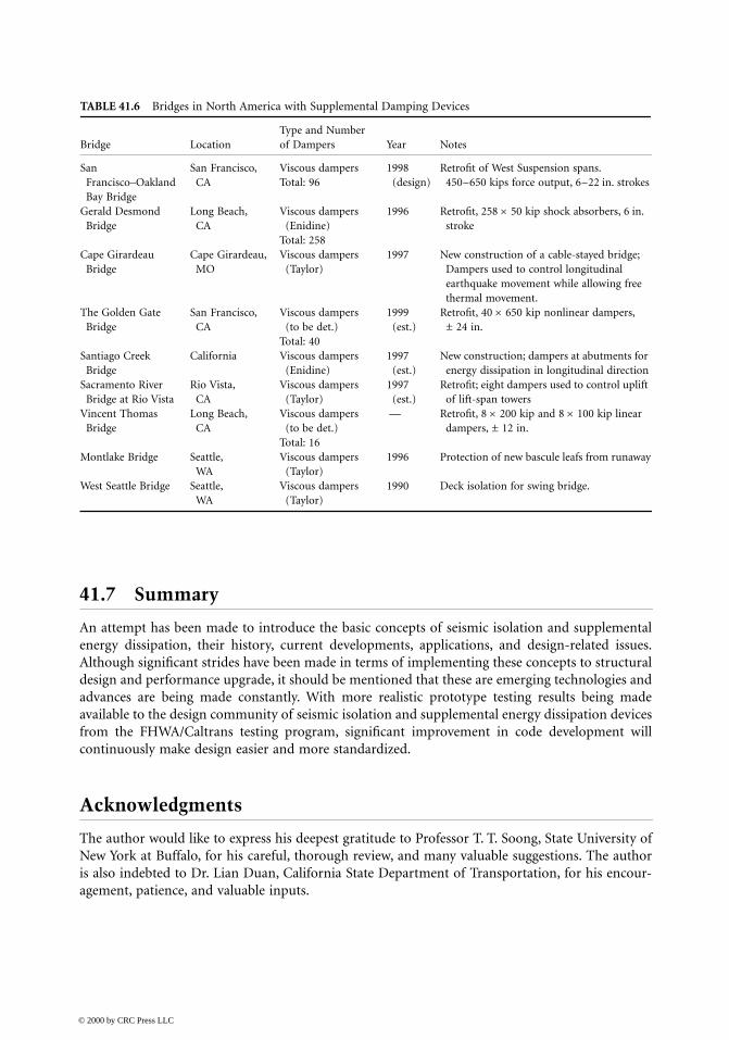
41.7 Summary
An attempt has been made to introduce the basic concepts of seismic isolation and supplementalenergy dissipation, their history, current developments, applications, and design-related issues.Although significant strides have been made in terms of implementing these concepts to structuraldesign and performance upgrade, it should be mentioned that these are emerging technologies andadvances are being made constantly. With more realistic prototype testing results being madeavailable to the design community of seismic isolation and supplemental energy dissipation devicesfrom the FHWA/Caltrans testing program, significant improvement in code development willcontinuously make design easier and more standardized.
Acknowledgments
The author would like to express his deepest gratitude to Professor T. T. Soong, State University ofNew York at Buffalo, for his careful, thorough review, and many valuable suggestions. The authoris also indebted to Dr. Lian Duan, California State Department of Transportation, for his encour-agement, patience, and valuable inputs.
TABLE 41.6 Bridges in North America with Supplemental Damping Devices
Bridge LocationType and Number of Dampers Year Notes
San Francisco–Oakland Bay Bridge
San Francisco, CA
Viscous dampersTotal: 96
1998(design)
Retrofit of West Suspension spans. 450~650 kips force output, 6~22 in. strokes
Gerald Desmond Bridge
Long Beach, CA
Viscous dampers (Enidine)
Total: 258
1996 Retrofit, 258 × 50 kip shock absorbers, 6 in. stroke
Cape Girardeau Bridge
Cape Girardeau, MO
Viscous dampers (Taylor)
1997 New construction of a cable-stayed bridge; Dampers used to control longitudinal earthquake movement while allowing free thermal movement.
The Golden Gate Bridge
San Francisco, CA
Viscous dampers (to be det.)
Total: 40
1999 (est.)
Retrofit, 40 × 650 kip nonlinear dampers, ± 24 in.
Santiago Creek Bridge
California Viscous dampers (Enidine)
1997 (est.)
New construction; dampers at abutments for energy dissipation in longitudinal direction
Sacramento River Bridge at Rio Vista
Rio Vista, CA
Viscous dampers (Taylor)
1997 (est.)
Retrofit; eight dampers used to control uplift of lift-span towers
Vincent Thomas Bridge
Long Beach, CA
Viscous dampers (to be det.)
Total: 16
— Retrofit, 8 × 200 kip and 8 × 100 kip linear dampers, ± 12 in.
Montlake Bridge Seattle, WA
Viscous dampers (Taylor)
1996 Protection of new bascule leafs from runaway
West Seattle Bridge Seattle, WA
Viscous dampers (Taylor)
1990 Deck isolation for swing bridge.
© 2000 by CRC Press LLC

References
1. Applied Technology Council, Improved Seismic Design Criteria for California Bridges: ProvisionalRecommendations, ATC-32, Applied Technology Council, Redwood City, 1996.
2. Housner, G. W., Bergman, L. A., Caughey, T. K., Chassiakos, A. G., Claus, R. O., Masri, S. F.,Seklton, R. E., Soong, T. T., Spencer, B. F., and Yao, J. T. P., Structural control: past, present, andfuture, J. Eng. Mech. ASCE, 123(9), 897–971.
3. Soong, T. T., and Gargush, G. F., Passive energy dissipation and active control, in Structure Engi-neering Handbook, Chen, W. F., Ed., CRC Press, Boca Raton, FL, 1997.
4. Soong, T. T. and Gargush, G. F., Passive Energy Dissipation Systems in Structural Engineering, JohnWiley & Sons, New York, 1997.
5. Housener, G. W. and Jennings, P. C., Earthquake Design Criteria, Earthquake Engineering ResearchInstitute, 1982.
6. Newmark, N. M. and Hall, W. J., Procedures and Criteria for Earthquake Resistant Design, BuildingPractice for Disaster Mitigation, Department of Commerce, Feb. 1973.
7. Dynamic Isolation Systems, Force Control Bearings for Bridges — Seismic Isolation Design, Rev. 4,Lafayette, CA, Oct. 1994.
8. Clough, R. W. and Penzien, J., Dynamics of Structures, 2nd ed., McGraw-Hill, New York, 1993.9. Zhang, R., Soong, T. T., and Mahmoodi, P., Seismic response of steel frame structures with added
viscoelastic dampers, Earthquake Eng. Struct. Dyn., 18, 389–396, 1989.10. Earthquake Protection Systems, Friction Pendulum Seismic Isolation Bearings, Product Technical
Information, Earthquake Protection Systems, Emeriville, CA, 1997.11. Liu, D. W, Nobari, F. S., Schamber, R. A., and Imbsen, R. A., Performance based seismic retrofit
design of Benicia–Martinez bridge, in Proceedings, National Seismic Conference on Bridges andHighways, Sacramento, CA, July 1997.
12. Constantinou, M. C. and Symans, M. D., Seismic response of structures with supplemental damp-ing, Struct. Design Tall Buildings, 2, 77–92, 1993.
13. Ingham, T. J., Rodriguez, S., Nader, M. N., Taucer, F, and Seim, C., Seismic retrofit of the GoldenGate Bridge, in Proceedings, National Seismic Conference on Bridges and Highways, Sacramento,CA, July 1997.
14. Taylor Devices, Sample Technical Specifications for Viscous Damping Devices, Taylor Devices, Inc.,North Tonawanda, NY, 1996.
15. Lin, R. C., Liang, Z., Soong, T. T., and Zhang, R., An Experimental Study of Seismic StructuralResponse with Added Viscoelastic Dampers, Report No. NCEER-88-0018, National Center ForEarthquake Engineering Research, State University of New York at Buffalo, February, 1988.
16. Crosby, P., Kelly, J. M., and Singh, J., Utilizing viscoelastic dampers in the seismic retrofit of athirteen story steel frame building, Structure Congress, XII, Atlanta, GA, 1994.
17. Skinner, R. I., Kelly, J. M., and Heine, A. J., Hysteretic dampers for earthquake resistant structures,Earthquake Eng. Struct. Dyn., 3, 297–309, 1975.
18. Pall, A. S. and Pall, R., Friction-dampers used for seismic control of new and existing buildings incanada, in Proceedings ATC 17-1 Seminar on Isolation, Energy Dissipation and Active Control, SanFrancisco, CA, 1992.
19. AASHTO, Guide Specifications for Seismic Isolation Design, American Association of State Highwayand Transportation Officials, Washington, D.C., June 1991.
20. FEMA, NEHRP Recommended Provisions for Seismic Regulations for New Buildings, 1994 ed.,Federal Emergency Management Agency, Washington, D.C., May 1995.
21. EERC/Berkeley, Pre-qualification Testing of Viscous Dampers for the Golden Gate Bridge SeismicRehabilitation Project, A Report to T. Y. Lin International, Inc., Report No. EERCL/95-03, Earth-quake Engineering Research Center, University of California at Berkeley, December 1995.
© 2000 by CRC Press LLC

22. AASHTO, Standard Specifications for Highway Bridges, 16th ed., American Association of StateHighway and Transportaion Officials, Washington, D.C., 1996.
23. Priestley, M. J. N, Seible, F., and Calvi, G. M., Seismic Design and Retrofit of Bridges, John Wileyan&& Sons, New York, 1996.
24. Whittaker, A., Tentative General Requirements for the Design and Construction of StructuresIncorporating Discrete Passive Energy Dissipation Devices, ATC-15-4, Redwood City, CA, 1994.
25. Applied Technology Council, BSSC Seismic Rehabilitation Projects, ATC-33.03 (Draft), RedwoodCity, CA, .
26. AASHTO-T3 Committee Task Group, Guide Specifications for Seismic Isolation Design, T3 Com-mittee Task Group Draft Rewrite, America Association of State Highway and TransportationOfficials, Washington, D.C., May, 1997.
© 2000 by CRC Press LLC


![SEISMIC ROOF ISOLATION OF HALKAPINAR … · most efficient seismic isolation solution for the Halkapınar Gymnasium. In this thesis, theory of seismic isolation, ... [18] (From AASHTO](https://img.dokumen.tips/doc/110x75/5b5ba6ce7f8b9a905c8e7903/seismic-roof-isolation-of-halkapinar-most-efficient-seismic-isolation-solution.jpg)