Embed Size (px)
Citation preview

CHAPTER 4 STRESSES IN SOIL MASS
4.1 DEFIFINTIONS • VERTTICAL STRESS
Occurs due to internal or external applied load such as, overburden pressure, weight of structure and earthquake loads.
• HORIZONTAL STRESS Occurs due to vertical stress or earth pressure, water pressure, wind loads or earthquake horizontal loads.
• ISOBAR It is a contour connecting all points below the ground surface of equal intensity of pressure.
• PRESSURE BULB The zone in a loaded soil mass bounded by an isobar of a given pressure intensity is called a pressure bulb for that intensity.
4.2 CONTACT PRESSURE The analysis of Borowicka (1938) shows that the distribution of contact stress was
dependent on a non-dimensional factor defined as: 3
s
f
f2
s2
r bT
EE
11
61k ⎟
⎠⎞
⎜⎝⎛⎟⎟⎠
⎞⎜⎜⎝
⎛⎟⎟⎠
⎞⎜⎜⎝
⎛
ν−
ν−= ……....................……….….…..(4.1)
where: sν and fν = Poisson's ratio for soil and foundation materials, respectively, sE and fE = Young's modulus for soil and foundation materials, respectively, T = thickness of foundation, B = half-width for strip footing; or radius for circular footing, rk = 0 indicates a perfectly flexible foundation; or ∞ means a perfectly rigid foundation. The actual soil pressures distributions of rigid and flexible footings resting on sand and clay soils are shown in Figures (4.1 and 4.2).
Prepared by: Dr. Farouk Majeed Muhauwiss Civil Engineering Department – College of Engineering
Tikrit University

Foundatio
4.3 AS
(1) S(2) Is(3) H(4) E(5) S(6) N
th STRES
(1) P• BThis
load actindistributi
n Engineering
(a)
(a)
SSUMPTSemi-infinitesotropic; the
HomogeneouElastic and obStresses at a pNegative valuhe principle
SS INCRPOINT LO
BOUSSINESmethod can ng on the suon) is a cylin
g
) Flexible
Fig
) Flexible
Fig
TIONS: T in extent; x
e soil has samus, beys Hook'spoint due to ues of loadinof superposi
REASE DOAD SQ METHObe used for
urface, its nnder in two-
gure (4.1): F
gure (4.2): F
The soil is as and y are in
me propertie
law; the soimore than o
ng can be useition was use
DUE TO
OD FOR HOr point loadsature at dep
-dimensional
2
Foundations
Foundations
ssumed as: nfinite but ths in all direc
il has linear one surface led if the streed.
O DIFFER
OMOGENEs acts directlpth z and radl condition a
s on sand.
s on clay.
he depth z hactions,
relationshipoad are obta
esses due to
RENT LO
EOUS SOILly at or outsdius r accorand a sphere
Chapter 4: St
(b) Rigid
(b) Rigid
as a limit val
, ained by supexcavations
OADING
L: side the centrding to (sim
in three-dim
tresses in Soil
lue (Half-spa
erposition, awere requir
G
ter. For a cemple radial smensional ca
Mass
ace),
and red or
entral stress ase.

Foundation Engineering Chapter 4: Stresses in Soil Mass
3
The vertical stress increase below or outside the point of load application is calculated as:
b2z Az.Q
=σ ……...........................……….………...…….…...(4.2)
where: 2/5
2b
)zr(1
.2/3A
⎥⎦⎤
⎢⎣⎡ +
π=
• WESTERGAARD METHOD FOR STRATIFIED SOIL:
[ ]
2/32
2z
)zr()22/()21(
)22/()21(
z.2Q
⎭⎬⎫
⎩⎨⎧ +μ−μ−
μ−μ−
π=σ
……......................(4.3a) where: =μ Poisson's ratio.
when =μ 0: W2z Az.Q
=σ …….........................……….………...…….….(4.3b)
where: 2/32
W
)zr(21
./1A
⎥⎦⎤
⎢⎣⎡ +
π= ; Values of WA can be tabulated for different values of μ as:
r/z WA
Note that : At (r/z ≈1.8 ) both Boussinessq
and Westergaard methods give equal values of zσ .
=μ 0 =μ 0.4
0.0 0.2 0.8 1.0 2.0 3.0 4.0
0.3183 0.2836 0.0925 0.0613 0.0118 0.0038 0.0017
0.9549 0.6916 0.0897 0.0516 0.0076 0.0023 0.0010
Isobars
Stress bulb
G.S.
Q
Z
G.S.
Q
r
zσ
Figure (4.3): Vertical stress due to point load.

Foundatio
Example
tha. Ab. A
Solution
(a) Ffo
n Engineering
e (4.1): A he vertical st
Along the depAt depth z = 2
: From Bous
or r = 2m,ollowing tab
z (m)
0.0 0.4 0.8 1.2 1.6 2.0 2.4 2.8 3.6 5.0 10.0
g
concentratetress zσ for pth for r = 2m2m.
ssinesq’s equ
, the valuesle and the di
) z/r ∞ 5.0 2.5 1.67 1.25 1.00 0.83 0.71 0.56 0.40 0.20
ed point loadeach of the m, and
uation: σ
s of zσ at vistribution o
bA 0
0.00014 0.00337 0.01712 0.04543 0.08440 0.12775 0.17035 0.24372 0.32946 0.43287
4
d Q acts verfollowing ca
b2z Az.Q
=σ
various arbif zσ with de
2z 0
0.16 60.64 11.44 02.56 04.00 05.76 07.84 012.96 025.00 0
100.00 0
Figure
rtically at theases:
b where:
itrarily selecepth is show
2z/Q σ∞ I
6.250Q 1.563Q 0.694Q 0.391Q 0.250Q 0.174Q 0.128Q .0772Q .0400Q .0100Q
e (4.4 a): zσa fixpoin
Chapter 4: St
e ground sur
b
1
A
⎢⎣⎡ +
=
cted depths wn in Figure
zσ )m/Q( 2
ndeterminate0.0009Q 0.0053Q 0.0119Q 0.0178Q 0.0211Q 0.0222Q 0.217Q 0.0188Q 0.0132Q 0.0043Q
distribution
xed radial dnt of surface
tresses in Soil
rface. Deter
2/52)
zr(
.2/3
⎥⎦⎤+
π
are given in(4.4 a).
) e
with depth adistance from
e load.
Mass
rmine
n the
at m

Foundatio
(b) A
fo
Example
Solution
n Engineering
At depth z = ollowing tab
r (m) 0.0 0.4 0.8 1.2 1.6 2.0 2.4 2.8 3.6 5.0 10.0
e (4.2): Q, the verticaand 4m, th
: From Bou
zσ for zdistributio
F
g
2m, the valle and the di
z/r 0
0.2 0.4 0.6 0.8 1.0 1.2 1.4 1.8 2.5 5.0
is a concental stress zσhen plot the
ussinesq’s eq
z = 1, 2, 3ons with hor
Figure (4.4 b
ues of zσ fistribution o
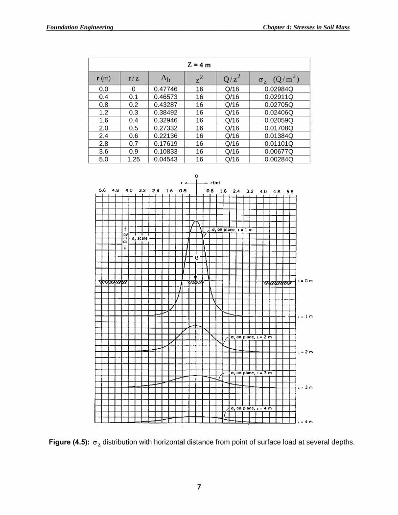
bA 0.47746 0.43287 0.32946 0.22136 0.13862 0.08440 0.05134 0.03168 0.01290 0.00337 0.00014
trated point for various
zσ distribut
quation: σ
, and 4m dizontal dista
b): zσ distribdistance
5
for various hf zσ with r
2z 4.0 04.0 04.0 04.0 04.0 04.0 04.0 04.0 04.0 04.0 04.0 0
load acts ves values of htion for all z
2z Az.Q
=σ
depths is giances are sho
bution with de from point
horizontal di is shown in
2z/Q σ0.25Q 0.25Q 0.25Q 0.25Q 0.25Q 0.25Q 0.25Q 0.25Q 0.25Q 0.25Q 0.25Q
rtically at thhorizontal didepths.
bA where:
iven in the own in Figur
depth at a fixof surface lo
Chapter 4: St
istances of rn Figure (4.4
zσ )m/Q( 2
0.1194Q 0.1082Q 0.0824Q 0.0553Q 0.0347Q 0.0211Q 0.0129Q 0.0079Q 0.0032Q 0.0008Q 0.0001Q
he ground suistances r an
b
1
A
⎢⎣⎡ +
=
following re (4.5).
xed radial oad.
tresses in Soil
r are given in4 b).
)
urface. Deternd at z = 1,
2/52)
zr(
.2/3
⎥⎦⎤+
π
tables and
Mass
n the
rmine 2, 3,
their

Foundation Engineering Chapter 4: Stresses in Soil Mass
6
z = 1 m
r (m) z/r bA 2z 2z/Q zσ )m/Q( 2 0.0 0 0.47746 1.0 Q 0.47746Q 0.4 0.4 0.32946 1.0 Q 0.32946Q 0.8 0.8 0.13862 1.0 Q 0.13862Q 1.2 1.2 0.05134 1.0 Q 0.05134Q 1.6 1.6 0.01997 1.0 Q 0.01997Q 2.0 2.0 0.00854 1.0 Q 0.00854Q 2.4 2.4 0.00402 1.0 Q 0.00402Q 2.8 2.8 0.00206 1.0 Q 0.00206Q 3.6 3.6 0.00066 1.0 Q 0.00066Q 5.0 5.0 0.00014 1.0 Q 0.00014Q
z = 2 m
r (m) z/r bA 2z 2z/Q zσ )m/Q( 2 0.0 0 0.47746 4.0 0.25Q 0.1194Q 0.4 0.2 0.43287 4.0 0.25Q 0.1082Q 0.8 0.4 0.32946 4.0 0.25Q 0.0824Q 1.2 0.6 0.22136 4.0 0.25Q 0.0553Q 1.6 0.8 0.13862 4.0 0.25Q 0.0347Q 2.0 1.0 0.08440 4.0 0.25Q 0.0211Q 2.4 1.2 0.05134 4.0 0.25Q 0.0129Q 2.8 1.4 0.03168 4.0 0.25Q 0.0079Q 3.6 1.8 0.01290 4.0 0.25Q 0.0032Q 5.0 2.5 0.00337 4.0 0.25Q 0.0008Q
z = 3 m
r (m) z/r bA 2z 2z/Q zσ )m/Q( 2 0.0 0 0.47746 9.0 Q/9 0.0531Q 0.4 0.1333 0.45630 9.0 Q/9 0.0507Q 0.8 0.2666 0.40200 9.0 Q/9 0.0447Q 1.2 0.4000 0.32950 9.0 Q/9 0.0366Q 1.6 0.5333 0.25555 9.0 Q/9 0.0284Q 2.0 0.6666 0.19060 9.0 Q/9 0.0212Q 2.4 0.8000 0.13862 9.0 Q/9 0.0154Q 2.8 0.9333 0.09983 9.0 Q/9 0.0111Q 3.6 1.2000 0.05134 9.0 Q/9 0.0057Q 5.0 3.3333 0.01710 9.0 Q/9 0.0019Q
Foundatio
Figure (
n Engineering
r (m) 0.0 0.4 0.8 1.2 1.6 2.0 2.4 2.8 3.6 5.0
(4.5): zσ dis
g
z/r 0
0.1 0.2 0.3 0.4 0.5 0.6 0.7 0.9 1.25
tribution with
bA 0.47746 0.46573 0.43287 0.38492 0.32946 0.27332 0.22136 0.17619 0.10833 0.04543
h horizontal
7
z = 4 m
2z 16 16 16 16 16 16 16 16 16 16
distance fro
2z/Q σQ/16 Q/16 Q/16 Q/16 Q/16 Q/16 Q/16 Q/16 Q/16 Q/16
om point of s
Chapter 4: St
zσ )m/Q( 2
0.02984Q 0.02911Q 0.02705Q 0.02406Q 0.02059Q 0.01708Q 0.01384Q 0.01101Q 0.00677Q 0.00284Q
surface load
tresses in Soil
)
at several d
Mass
epths.
Foundation Engineering Chapter 4: Stresses in Soil Mass
8
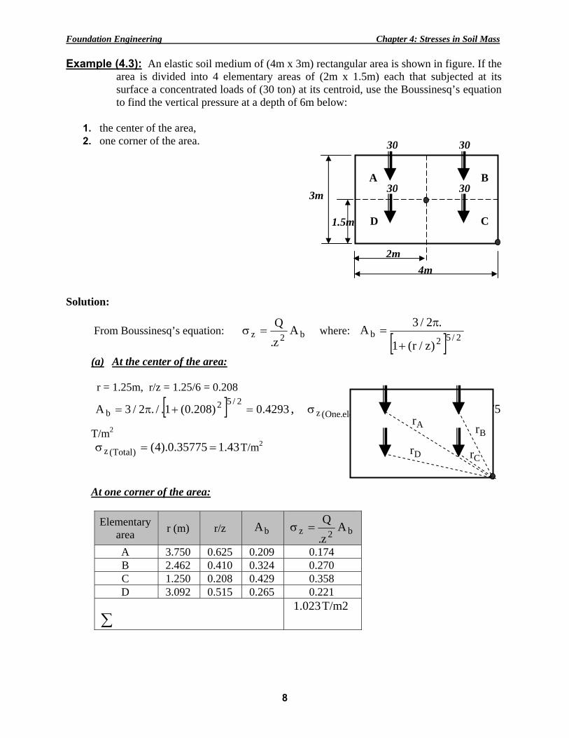
Example (4.3): An elastic soil medium of (4m x 3m) rectangular area is shown in figure. If the area is divided into 4 elementary areas of (2m x 1.5m) each that subjected at its surface a concentrated loads of (30 ton) at its centroid, use the Boussinesq’s equation to find the vertical pressure at a depth of 6m below:
1. the center of the area, 2. one corner of the area.
Solution:
From Boussinesq’s equation: b2z Az.Q
=σ where: [ ] 2/52
b)z/r(1
.2/3A+
π=
(a) At the center of the area: r = 1.25m, r/z = 1.25/6 = 0.208
[ ] 4293.0)208.0(1./.2/3A2/52
b =+π= , 35775.0)4293.0(630
2)element.One(z ==σ
T/m2 43.135775.0).4()Total(z ==σ T/m2
At one corner of the area: Elementary
area r (m) r/z bA b2z Az.Q
=σ
A 3.750 0.625 0.209 0.174 B 2.462 0.410 0.324 0.270 C 1.250 0.208 0.429 0.358 D 3.092 0.515 0.265 0.221
∑
T/m2 1.023
4m
3m
2m
1.5m
30 30
30 30A
D
B
C
Ar
DrBr
Cr
Foundation Engineering Chapter 4: Stresses in Soil Mass
9
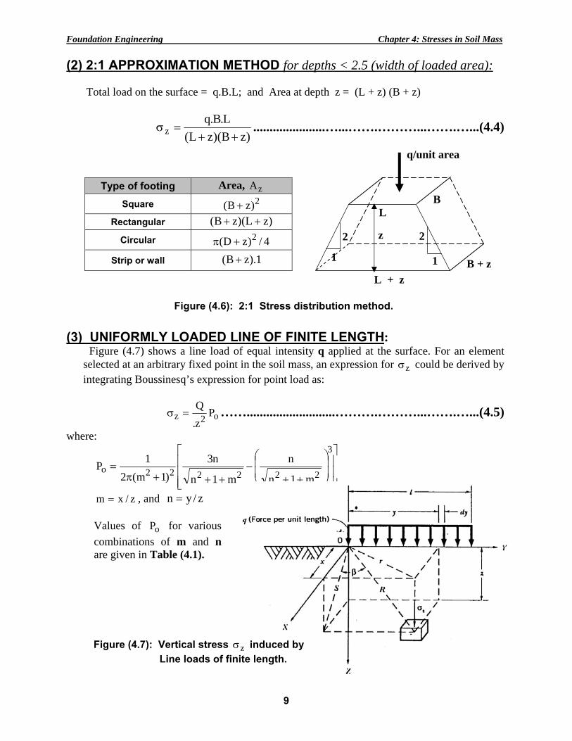
(2) 2:1 APPROXIMATION METHOD for depths < 2.5 (width of loaded area): Total load on the surface = q.B.L; and Area at depth z = (L + z) (B + z)
)zB)(zL(L.B.q
z ++=σ ......................…...…….………...…….…...(4.4)
(3) UNIFORMLY LOADED LINE OF FINITE LENGTH: Figure (4.7) shows a line load of equal intensity q applied at the surface. For an element
selected at an arbitrary fixed point in the soil mass, an expression for zσ could be derived by integrating Boussinesq’s expression for point load as:
o2z Pz.Q
=σ ……...........................……….………...…….…...(4.5)
where:
⎥⎥⎥
⎦
⎤
⎢⎢⎢
⎣
⎡
⎟⎟⎠
⎞
⎜⎜⎝
⎛
++−
+++π=
3
222222om1n
n
m1n
n3)1m(2
1P
z/xm = , and z/yn =
z
q/unit area
B L
B + z L + z
2
1
2
1
Type of footing Area, zA Square 2)zB( +
Rectangular )zL)(zB( ++ Circular 4/)zD( 2+π
Strip or wall 1).zB( +
Figure (4.6): 2:1 Stress distribution method.
Values of oP for various combinations of m and n are given in Table (4.1).
Figure (4.7): Vertical stress zσ induced by Line loads of finite length.
Foundation Engineering Chapter 4: Stresses in Soil Mass
10
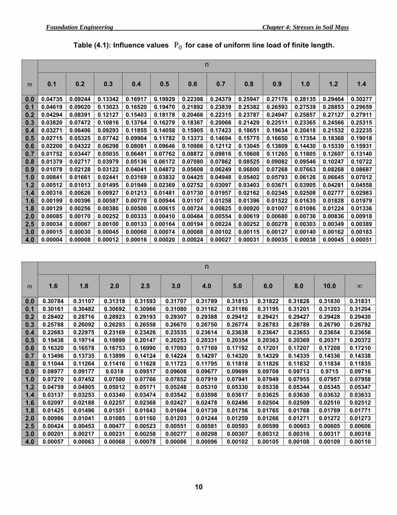
Table (4.1): Influence values 0P for case of uniform line load of finite length.
m
n
0.1
0.2
0.3
0.4
0.5
0.6
0.7
0.8
0.9
1.0
1.2
1.4
0.0 0.04735 0.09244 0.13342 0.16917 0.19929 0.22398 0.24379 0.25947 0.27176 0.28135 0.29464 0.30277 0.1 0.04619 0.09020 0.13023 0.16520 0.19470 0.21892 0.23839 0.25382 0.26593 0.27539 0.28853 0.29659 0.2 0.04294 0.08391 0.12127 0.15403 0.18178 0.20466 0.22315 0.23787 0.24947 0.25857 0.27127 0.27911 0.3 0.03820 0.07472 0.10816 0.13764 0.16279 0.18367 0.20066 0.21429 0.22511 0.23365 0.24566 0.25315 0.4 0.03271 0.06406 0.09293 0.11855 0.14058 0.15905 0.17423 0.18651 0.19634 0.20418 0.21532 0.22235 0.5 0.02715 0.05325 0.07742 0.09904 0.11782 0.13373 0.14694 0.15775 0.16650 0.17354 0.18368 0.19018 0.6 0.02200 0.04322 0.06298 0.08081 0.09646 0.10986 0.12112 0.13045 0.13809 0.14430 0.15339 0.15931 0.7 0.01752 0.03447 0.05035 0.06481 0.07762 0.08872 0.09816 0.10608 0.11265 0.11805 0.12607 0.13140 0.8 0.01379 0.02717 0.03979 0.05136 0.06172 0.07080 0.07862 0.08525 0.09082 0.09546 0.10247 0.10722 0.9 0.01078 0.02128 0.03122 0.04041 0.04872 0.05608 0.06249 0.06800 0.07268 0.07663 0.08268 0.08687 1.0 0.00841 0.01661 0.02441 0.03169 0.03832 0.04425 0.04948 0.05402 0.05793 0.06126 0.06645 0.07012 1.2 0.00512 0.01013 0.01495 0.01949 0.02369 0.02752 0.03097 0.03403 0.03671 0.03905 0.04281 0.04558 1.4 0.00316 0.00626 0.00927 0.01213 0.01481 0.01730 0.01957 0.02162 0.02345 0.02508 0.02777 0.02983 1.6 0.00199 0.00396 0.00587 0.00770 0.00944 0.01107 0.01258 0.01396 0.01522 0.01635 0.01828 0.01979 1.8 0.00129 0.00256 0.00380 0.00500 0.00615 0.00724 0.00825 0.00920 0.01007 0.01086 0.01224 0.01336 2.0 0.00085 0.00170 0.00252 0.00333 0.00410 0.00484 0.00554 0.00619 0.00680 0.00736 0.00836 0.00918 2.5 0.00034 0.00067 0.00100 0.00133 0.00164 0.00194 0.00224 0.00252 0.00278 0.00303 0.00349 0.00389 3.0 0.00015 0.00030 0.00045 0.00060 0.00074 0.00088 0.00102 0.00115 0.00127 0.00140 0.00162 0.00183 4.0 0.00004 0.00008 0.00012 0.00016 0.00020 0.00024 0.00027 0.00031 0.00035 0.00038 0.00045 0.00051
m
n
1.6
1.8
2.0
2.5
3.0
4.0
5.0
6.0
8.0
10.0
∞
0.0 0.30784 0.31107 0.31318 0.31593 0.31707 0.31789 0.31813 0.31822 0.31828 0.31830 0.31831 0.1 0.30161 0.30482 0.30692 0.30966 0.31080 0.31162 0.31186 0.31195 0.31201 0.31203 0.31204 0.2 0.28402 0.28716 0.28923 0.29193 0.29307 0.29388 0.29412 0.29421 0.29427 0.29428 0.29430 0.3 0.25788 0.26092 0.26293 0.26558 0.26670 0.26750 0.26774 0.26783 0.26789 0.26790 0.26792 0.4 0.22683 0.22975 0.23169 0.23426 0.23535 0.23614 0.23638 0.23647 0.23653 0.23654 0.23656 0.5 0.19438 0.19714 0.19899 0.20147 0.20253 0.20331 0.20354 0.20363 0.20369 0.20371 0.20372 0.6 0.16320 0.16578 0.16753 0.16990 0.17093 0.17169 0.17192 0.17201 0.17207 0.17208 0.17210 0.7 0.13496 0.13735 0.13899 0.14124 0.14224 0.14297 0.14320 0.14329 0.14335 0.14336 0.14338 0.8 0.11044 0.11264 0.11416 0.11628 0.11723 0.11795 0.11818 0.11826 0.11832 0.11834 0.11835 0.9 0.08977 0.09177 0.0318 0.09517 0.09608 0.09677 0.09699 0.09708 0.09713 0.9715 0.09716 1.0 0.07270 0.07452 0.07580 0.07766 0.07852 0.07919 0.07941 0.07949 0.07955 0.07957 0.07958 1.2 0.04759 0.04905 0.05012 0.05171 0.05248 0.05310 0.05330 0.05338 0.05344 0.05345 0.05347 1.4 0.03137 0.03253 0.03340 0.03474 0.03542 0.03598 0.03617 0.03625 0.03630 0.03632 0.03633 1.6 0.02097 0.02188 0.02257 0.02368 0.02427 0.02478 0.02496 0.02504 0.02509 0.02510 0.02512 1.8 0.01425 0.01496 0.01551 0.01643 0.01694 0.01739 0.01756 0.01765 0.01768 0.01769 0.01771 2.0 0.00986 0.01041 0.01085 0.01160 0.01203 0.01244 0.01259 0.01266 0.01271 0.01272 0.01273 2.5 0.00424 0.00453 0.00477 0.00523 0.00551 0.00581 0.00593 0.00599 0.00603 0.00605 0.00606 3.0 0.00201 0.00217 0.00231 0.00258 0.00277 0.00298 0.00307 0.00312 0.00316 0.00317 0.00318 4.0 0.00057 0.00063 0.00068 0.00078 0.00086 0.00096 0.00102 0.00105 0.00108 0.00109 0.00110
Foundation Engineering Chapter 4: Stresses in Soil Mass
11
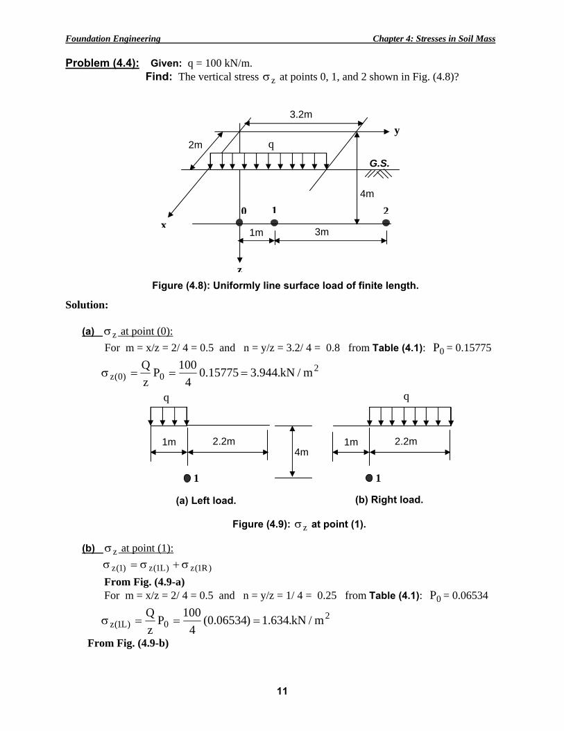
Problem (4.4): Given: q = 100 kN/m. Find: The vertical stress zσ at points 0, 1, and 2 shown in Fig. (4.8)?
Solution:
(a) zσ at point (0): For m = x/z = 2/ 4 = 0.5 and n = y/z = 3.2/ 4 = 0.8 from Table (4.1): 0P = 0.15775
20)0(z m/kN.944.315775.0
4100P
zQ
===σ
(b) zσ at point (1): )R1(z)L1(z)1(z σ+σ=σ From Fig. (4.9-a) For m = x/z = 2/ 4 = 0.5 and n = y/z = 1/ 4 = 0.25 from Table (4.1): 0P = 0.06534
20)L1(z m/kN.634.1)06534.0(
4100P
zQ
===σ
From Fig. (4.9-b)
G.S.
2m
1m
3.2m
q
x
y
4m
0 1 2
3m
zFigure (4.8): Uniformly line surface load of finite length.
(a) Left load.
1m
q
1
2.2m 1m
q
1
2.2m
(b) Right load.
Figure (4.9): zσ at point (1).
4m

Foundation Engineering Chapter 4: Stresses in Soil Mass
12
For m = x/z = 2/ 4 = 0.5 and n = y/z = 2.2/ 4 = 0.55 from Table (4.1): 0P = 0.12578
20)R1(z m/kN.144.3)12578.0(
4100P
zQ
===σ
2)R1(z)L1(z)1(z m/kN.778.4144.3634.1 =+=σ+σ=σ
(c) zσ at point (2): )R2(z)L2(z)2(z σ−σ=σ From Fig. (4.10-a): For m = x/z = 2/ 4 = 0.5 and n = y/z = 4/ 4 = 1.0 from Table (4.1): 0P = 0.1735 From Fig. (4.10-b): For m = x/z = 2/ 4 = 0.5 and n = y/z = 0.8/ 4 = 0.2 from Table (4.1): 0P = 0.0532
2)R2(z)L2(z)2(z m/kN.01.3)0532.01735.0(
4100
=−=σ−σ=σ
Problem (4.5): Given: Two walls loaded as shown in Fig.. Find: the vertical stress zσ at z = 8m below point A? Solution:
Wall BC: 26m: For m = x/z = 3/ 8 = 0.375 and n = y/z = 26/ 8 = 3.25 From Table (4.1): 0P = 0.26 4m: For m = x/z = 3/ 8 = 0.375 and n = y/z = 4/ 8 = 0.5 From Table (4.1): 0P = 0.15
20)BC(z m/kN.10.3)15.026.0(
860P
zq
=+==σ
Wall CD:
(a)
Extension
q
2
3.2m
Figure (4.10): zσ at point (2).
4m
0.8m
q
2
4m
(b)
m/kN60q = B
4m
30m C
D
3m
20mA
m/kN70q =

Foundation Engineering Chapter 4: Stresses in Soil Mass
13
3m: For m = x/z = 4/ 8 = 0.5 and n = y/z = 3/ 8 = 0.375 From Table (4.1): 0P = 0.09 17m: For m = x/z = 4/ 8 = 0.5 and n = y/z = 17/ 8 = 2.125 From Table (4.1): 0P = 0.20
20)CD(z m/kN.50.2)20.0009(
870P
zq
=+==σ
2
)A(z m/kN.6.550.210.3 =+=σ
(4) UNIFORMLY LOADED STRIP AREA:
To calculate the vertical stress under uniformly loaded strip area (see Figure 4.11).
Figure (4.11): Pressure bulbs for vertical stresses under strip load.
2.5
1.5
0.5
0.0
Z/B
1.0
∆
B/2
2.0
3.0
1.0 1.5 2.0 X/B
0.95 0.90 0.80 0.70 0.60
0.50
0.40
∆∆
0.30
0.20

Foundation Engineering Chapter 4: Stresses in Soil Mass
14
(5) TRIANGULAR LOADED STRIP AREA:
To calculate the vertical stress under triangular loaded strip area (see Figure 4.12).
Figure (4.12): Pressure bulbs for vertical stresses under triangular strip load.
(6) UNIFORMLY LOADED CIRCULAR AREA:
dA)z/r(1
1z.2.q3
2/52
022z ∫
π
=θ ⎥⎥⎦
⎤
⎢⎢⎣
⎡
+π=σ
where, θ= d.r21dA 2 ; which after integrating and simplifying leads to:
100xq.I o
z =σ …........................................................…...…..…...(4.5)
where, I = Influence factor depends on (z/r and x/r); expressed in percentage of surface contact pressure, oq , for vertical stress under uniformly loaded circular area (see Figure 4.13).
∆
0.0
Z/B
1.0
B/2
2.0
3.0
1.0 2.0X/B
0.9 0.7
0.5
0.4
∆∆
0.10
0.3
0.2
0.15
G.S.
2r
z
oq
zσ
x
r

Foundatio
Figure (4
Problem
Solution
n Engineering
4.13): InfluvertiAhlvi
m (٤.6): Given: A Find: the
(a) z = 2 (b) z = 2
: a. For z/
z =σ
b. For z/
z =σ
g
ence valuecal stress in, 1954, as
circular aree vertical str
2m directly u2m below and
/r = 2/1.6 =
1.(52
100q.I o =
/r = 2/1.6 =
10.(22
100q.I o =
s expresseunder un
cited by U.S
ea, r = 1.6m, ress zσ at: under the cend 2m away f
1.25 and x/
5200
)100(=
1.25 and x/
2200
)100(=
15
ed in perceniformly loa
S. Navy, 197
induces a so
nter of the cifrom the cen
/r = 0; from
kN/m2.
/r = 2/1.6 = 1
kN/m2.
ntage of suaded circul71).
oil pressure
ircular area.nter of the cir
Fig. (4.13):
1.25; from F
Chapter 4: St
rface contalar area (af
at the surfac
rcle.
: =I 52
Fig. (4.13):
tresses in Soil
act pressureafter Foster
ce of 100 kN
=I 22
Mass
e for and
N/m2.

Foundation Engineering Chapter 4: Stresses in Soil Mass
16
(6) UNIFORMLY LOADED RECTANGULAR OR SQUARE AREA: The vertical stress increase below the corner of a flexible rectangular or square loaded area is calculated as:
oq.Iz =σ …...................................................................…..…...(4.6) where, I = influence factor, depends on (m = B/z, and n = L/z) obtained from (Figure 4.14).
B
Z
oq
oz q.I=σ
G.S.
B
Z
oq
G.S.
L
Example (1): Example (2):
Example (3):
d
c
f a
e b
1 2
3 4 L
]IIII[q 4321oz +++=σ
]II[q abefabcdo)a(z −=σ
oq
Examples for Vertical stress under the corner of a uniformly loaded rectangular area.

Foundatio
Problem
n Engineering
Figur
m (4.7): Thpressure ia depth of
g
re (4.14): Va of
he plan of as 40 kN/m2.f (5m) below
2m
2m
alues of I foa flexible re
a foundation Determine t
w the point (x
3m
1
2
17
or vertical sectangular
n is given inthe vertical x).
3m
x
1.1.5m
3
4
stress belowarea (after F
n the Fig. bstress increm
3m
5m
Chapter 4: St
w the corneFadum, 1948)
below. The ment due to t
m
0
tresses in Soil
er ).
uniform cothe foundati
0.5m
Mass
ontact ion at

Foundation Engineering Chapter 4: Stresses in Soil Mass
18
Solution:
• Using Fig. (4.14) the following table of results can be prepared for z = 5m
Segment B L m = B/z n = L/z I 1 2 3 4
1.5 0.5 1.5 0.5
4.5 4.5 2.5 1.5
0.3 0.1 0.3 0.1
0.9 0.9 0.5 0.3
0.077 0.027 0.056 0.013
oz q.I=σ = (2)(40)[ 0.077 + 0.027 + 0.056 - 0.013] = 11.76 kN/m2 Problem (4.8): Determine the vertical stress increase at points (A) and (B) due to the loaded
area shown in Fig. knowing that A and B points are located at depth of (5m) below the foundation level.
Solution: (1) for point A:
• For half-circular area: From Fig. (4.13): for z = 5m, z/r = 5/1 = 5 and x/r = 0: I1 = 5.7 • For rectangular loaded area:
From Fig. (4.14): for z = 5m, m = B/z = 3/5 = 0.6 and n = L/z = 4/5 = 0.8: I2 = 0.125 for z = 5m, m = B/z = 3/5 = 0.6 and n = L/z =3/5 = 0.6: I3 = 0.107 ∴ zσ = (0.5)(200)(5.7/100) + (100)(0.125 + 0.107) = 28.9 kN/m2
(2) for point B: • For half-circular area: From Fig. (4.13): for z = 5m, z/r = 5/1 = 5 and x/r = 3/1 = 3: I1= 2.7 • For rectangular loaded area:
From Fig. (4.14): for z = 5m, m = B/z = 3/5 = 0.6 and n = L/z = 7/5 = 1.4: I2 = 0.147 ∴ zσ = (0.5)(200)(2.7/100) + (100)(0.147) = 17.4 kN/m2
3m 2m 2m
A
3m 1
3 B 200q 2 =
100q1 =
2
Foundatio
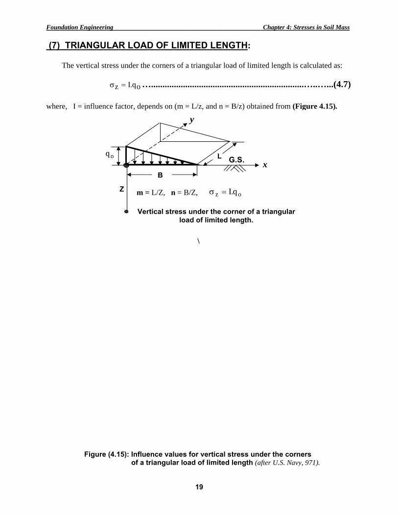
(7) TR The
where, I
n Engineering
RIANGUL
vertical stre
σ
I = influence
oq
Figure (4
g
LAR LOAD
ess under the
oq.Iz =σ …
e factor, depe
Z
o
m =
Ver
4.15): Influe of a tr
D OF LIM
e corners of a
…................
ends on (m =
B
= L/Z, n = B
rtical stressloa
ence valuesriangular lo
19
MITED LEN
a triangular
.................
= L/z, and n
\
z =σ
L
y
B/Z,
s under the ad of limite
s for verticaoad of limite
NGTH:
load of limit
.................
= B/z) obtai
oq.I=
G.S.
corner of a d length.
l stress unded length (af
Chapter 4: St
ted length is
.................
ined from (F
x
triangular
der the cornafter U.S. Navy
tresses in Soil
calculated a
...…..…...(
Figure 4.15)
ners vy, 971).
Mass
as:
(4.7)
).

Foundatio
(8) EM The
where, I
F
n Engineering
MBANKMEvertical stre
σI = influence
Figure (4.16
q
g
ENT LOAess under em
oq.Iz =σ …e factor depe
): Influence
Z
o
I =
b
Ver
ADING: mbankment lo…................
ends on (a/z,
e factor for e
a
= f (a/z, b/z);
rtical stress
20
oading is cal................. and b/z) det
embankmen
z .I=σ
a
;
s under emb
lculated as:.................termined fro
nt loading (
oq
G.S.
bankment lo
Chapter 4: St
.................om (Figure 4
(after Osterbe
x
oading.
tresses in Soil
...…..…...(4.16).
erg, 1957).
Mass
(4.8)

Foundation Engineering Chapter 4: Stresses in Soil Mass
21
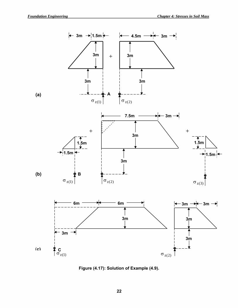
Problem (4.9): An embankment of (3m) high is to be constructed as shown in the figure below. If the unit weight of compacted soil is 19 kN/m3, calculate the vertical stress due to the embankment loading at (A), (B), and (C) points.
Solution: (1) Vertical stress at A:
From Fig. (4.17a): )2(z)1(zzA σ+σ=σ
Left-hand section: b/z = 1.5/3 = 0.5 and a/z = 3/3 = 1.0, from Fig. (4.16); 1I = 0.396 Right-hand section: b/z = 4.5/3 = 1.5 and a/z = 3/3 = 1.0, from Fig. (4.16); 2I = 0.477
q)II( 21zA +=σ = [0.396 + 0.477](19)(3) = 49.761 kN/m2 (2) Vertical stress at B:
From Fig. (4.17b): )3(z)2(z)1(zzB σ−σ+σ=σ
Left-hand section: b/z = 0/3 = 0 and a/z = 1.5/3 = 0.5, from Fig. (4.16); 1I = 0.140 Middle section: b/z =7.5/3 = 2.5 and a/z = 3/3 = 1.0, from Fig. (4.16); 2I = 0.493 Right-hand section: b/z = 0/3 = 0 and a/z = 1.5/3 = 0.5, from Fig. (4.16); 3I = 0.140
)q.I()q.I()q.I( 332211zB −+=σ
= (0.14)(19)(1.5) + (0.493)(19)(3) - (0.14)(19)(1.5) = 28.101 kN/m2 (3) Vertical stress at C:
Using Fig. (4.17c): )2(z)1(zzC σ−σ=σ
Left-hand section, b/z = 12/3 = 4 and a/z = 3/3 = 1.0, from Fig. (4.16); 1I = 0.498. Right-hand section, b/z = 3/3 = 1.0 and a/z = 3/3 = 1.0, from Fig. (4.16); 2I = 0.456.
q)II( 21zC −=σ = (0.498 - 0.456)(19)(3) = 2.394 kN/m2
4.5m
ABC
1.5m1.5m
6m
3m
3m19soil =γ kN/m3
1: 1 slope1: 1 slope
Foundation Engineering Chapter 4: Stresses in Soil Mass
22
3m
3m
3m
)2(zσ (c)
3m
C
6m
3m
3m
6m
)1(zσ
7.5m
)1(zσ
1.5m
3m
1.5m
+
3m
3m
)2(zσ(b)
+
)3(zσ
1.5m
1.5m
B
4.5m
)1(zσ
1.5m
3m 3m +
3m
3m
3m
3m
)2(zσ(a) A
Figure (4.17): Solution of Example (4.9).

Foundation Engineering Chapter 4: Stresses in Soil Mass
23
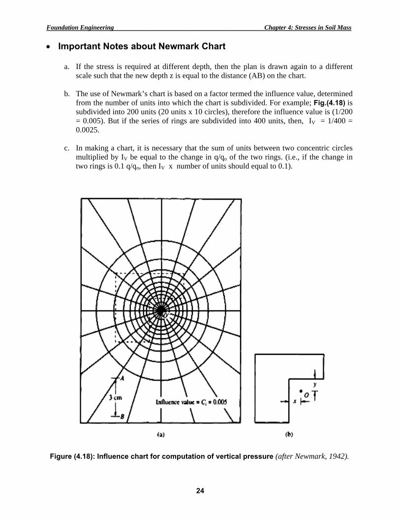
(9) ANY SHAPE LOADED AREA (NEWMARK CHART): The stress on an elemental area dA of soil due to surface contact pressure oq is calculated as:
dA])z/r(1[
1z.2
q3dq
2/522o
+π=
but dr.r.2dA π= ∴ ∫+
π
π=
r
02/522
o
])z/r(1[dr.r.2
z.2
q3q
or ⎪⎭
⎪⎬⎫
⎪⎩
⎪⎨⎧
+−= 2/3]2)z/r(1[
11oqq
1)q/q1()z/r( 3/2
o −−= − …...............................…..…....(4.9) Prepare a chart on transparent paper with ir circles as follows with °18 sectors:
oq/q 0.1 0.2 0.3 0.4 0.5 0.6 0.7 0.8 0.9 1.0 (r/z) 0.270 0.400 0.518 0.637 0.766 0.918 1.110 1.387 1.908 ∞
In this case, each circle of the chart is subdivided into 20 units, therefore the number of units for 10 circles = (20 units x 10 circles) = 200 and the influence value ( IV =1/200 = 0.005). If the scale distance (AB) is assumed = 5 cm, then:
ir (cm) 1.35 2 2.59 3.18 3.83 4.59 5.55 6.94 9.54 ∞ To estimate zσ : (1) Adopt a scale such that, the scale distance (AB) is equal to the required depth (z),
(2) Based on the scale adopted in (1), replot the plan of the loaded area, (3) Place the plan plotted in (2) on the Newmark chart in such a way that the point (P) at
which the vertical stress is required, (4) Count the number of blocks, N of the chart which fall inside the plan, and (5) calculate zσ as:
)N).(I.(q Vz =σ …........................................................….......(4.10)
where, Iv = Influence value of the chart ( see Figure 4.18).
Foundatio
• Imp
a.
b.
c.
Figure (
n Engineering
ortant No
If the stressscale such th
The use of Nfrom the nusubdivided = 0.005). B0.0025.
In making amultiplied btwo rings is
(4.18): Influ
g
otes abou
s is requiredhat the new
Newmark’s umber of uniinto 200 uni
But if the ser
a chart, it is by IV be equs 0.1 q/qo, the
ence chart
ut Newma
d at differendepth z is eq
chart is baseits into whicits (20 units ries of rings
necessary tual to the chen IV x num
for comput
24
ark Chart
nt depth, thenqual to the d
ed on a factoch the chart i
x 10 circlesare subdivi
that the sum hange in q/qomber of units
tation of ver
t
n the plan idistance (AB
or termed theis subdivideds), therefore ided into 40
of units beto of the twos should equ
rtical press
Chapter 4: St
s drawn agaB) on the cha
e influence vd. For examthe influenc0 units, then
tween two co rings. (i.e.,ual to 0.1).
ure (after N
tresses in Soil
ain to a diffrt.
value, determmple; Fig.(4.1ce value is (1n, IV = 1/4
concentric ci if the chang
Newmark, 19
Mass
ferent
mined 18) is 1/200 400 =
ircles ge in
42).

Foundation Engineering Chapter 4: Stresses in Soil Mass
25
Problem (4.10): The foundation plan shown in the figure below is subjected to a uniform
contact pressure of 40 kN/m2. Determine the vertical stress increment due to the foundation load at (5m) depth below the point (x).
Solution:
Using Fig. (4.18): N ≈ 58 )N).(I.(q Vz =σ = (40)(0.005)(58) = 11.6 kN/m2
3m 3m 3m
x 0.5m 2m
2m
1.5m 1.5m
1
2
3
4