Embed Size (px)
Citation preview

Chapter 4
Non-simultaneity from the classical wave equation
−from my book:
Understanding Relativistic Quantum Field Theory
Hans de Vries
October 30, 2009

2 Chapter
Contents
4 Non-simultaneity from the classical wave equation 14.1 Changing reference frames and non-simultaneity . . . . . . 24.2 Lorentz invariance of the wave equation . . . . . . . . . . 34.3 Observed simultaneity and Derived simultaneity . . . . . . 54.4 Everybody sees the same light-cone frame . . . . . . . . . 64.5 Passengers in rows and atoms in rows . . . . . . . . . . . . 84.6 The velocity dependent viewing angle . . . . . . . . . . . . 94.7 Simultaneity and the invariance of size . . . . . . . . . . . 104.8 The relative versus the absolute viewing angle . . . . . . . 124.9 The ellipsoids of simultaneity . . . . . . . . . . . . . . . . 164.10 From ellipsoids to spheres of simultaneity . . . . . . . . . 204.11 Step 1: From absolute to relative positions . . . . . . . . . 244.12 Step 2: Viewing while Lorentz contracted . . . . . . . . . 264.13 Simultaneity from the Spherical Mirror clock . . . . . . . 284.14 Reversal of Lorentz contraction . . . . . . . . . . . . . . . 324.15 Reversal of Time dilation . . . . . . . . . . . . . . . . . . 344.16 Simultaneity from Huygens principle . . . . . . . . . . . . 384.17 Simultaneity and the light wavefront direction . . . . . . . 394.18 The wavefront rotation of matter waves . . . . . . . . . . 424.19 Negative energy waves and wavefront rotation . . . . . . . 44

Chapter 4
Non-simultaneity from theclassical wave equation

2 Chapter 4. Non-simultaneity from the classical wave equation
4.1 Changing reference frames and non-simultaneity
There is nothing particular difficult in understanding what happens in asingle reference frame. Lorentz contraction is predicted for the movingstable solutions of the wave equations for massless and massive objects(See the chapter on the Klein Gordon equation for the latter). The effectof a slower moving clock is perfectly predicted by the fact that signals haveto travel a longer path in moving objects.
Nature’s magnificent skill’s as a perfect illusionist happens when we changefrom one reference frame to another reference frame. Both Lorentz contrac-tion and Time dilation seem to be ”undone” and perfectly reversed. Afterchanging to a new reference frame the effects now apply to the previousrest frame.
The trick Nature uses is that of changing simultaneity when changingreference frames. Essential for understanding Special Relativity is under-standing simultaneity: The mechanism which lead us to observe a differentsimultaneity also causes the reversal of Lorentz contraction and Time di-lation.
In this chapter we also want to understand this mechanism. Why do weperceive different simultanities in different reference frames? Here we willshow how this follows in its completeness from the classical physics ofpropagation. The physics of the wave equations. One can say, on onehand, that these equations comply with special relativity. However, onthe other hand one can demonstrate that they give rise to all of specialrelativity, and this includes its most puzzling aspect, that of simultaneity.
The single additional postulate we might need to make in classical physicsis about the preference of one reference frame above the others. As today,test with accuracies exceeding 1 part in 10−17 were not able to single outany reference frame above the others. That is, physics is the same in twodifferent reference with a precision better than that.
Such independency of reference frames assures to us humans that, for in-stance, live will go on as usual when the Milky Way has rotated over 180degrees (in approximately 100 million years) and we have to deal with areference frame which has a speed of 1.6 million kilometers per hour whencompared with our current reference frame.
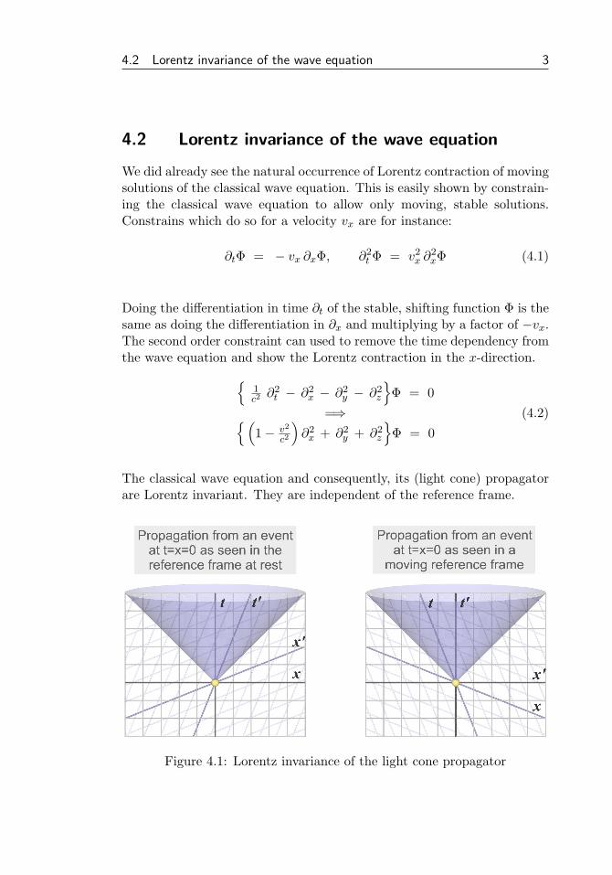
4.2 Lorentz invariance of the wave equation 3
4.2 Lorentz invariance of the wave equation
We did already see the natural occurrence of Lorentz contraction of movingsolutions of the classical wave equation. This is easily shown by constrain-ing the classical wave equation to allow only moving, stable solutions.Constrains which do so for a velocity vx are for instance:
∂tΦ = − vx ∂xΦ, ∂2t Φ = v2
x ∂2xΦ (4.1)
Doing the differentiation in time ∂t of the stable, shifting function Φ is thesame as doing the differentiation in ∂x and multiplying by a factor of −vx.The second order constraint can used to remove the time dependency fromthe wave equation and show the Lorentz contraction in the x-direction.{
1c2∂2t − ∂2
x − ∂2y − ∂2
z
}Φ = 0
=⇒{(1− v2
c2
)∂2x + ∂2
y + ∂2z
}Φ = 0
(4.2)
The classical wave equation and consequently, its (light cone) propagatorare Lorentz invariant. They are independent of the reference frame.
Figure 4.1: Lorentz invariance of the light cone propagator

4 Chapter 4. Non-simultaneity from the classical wave equation
To verify that the classical wave equation is Lorentz invariant we have todifferentiate along the coordinates of the transformed reference frame andto check that at each point the results are the same. (We’ll use c=1 here)(
∂2t′ − ∂2
x′ − ∂2y′ − ∂2
z′
)Φ =
(∂2t − ∂2
x − ∂2y − ∂2
z
)Φ (4.3)
We can do this transformation by using the chain rule to express the trans-formed differentials in rest frame differentials using the coefficients of theLorentz transform given by.
t′ = γ(t− βx)x′ = γ(x− βt)
}=⇒ ∂t
∂t′=∂x
∂x′= γ,
∂x
∂t′=
∂t
∂x′= −βγ (4.4)
The 1st and 2nd order derivatives expressed in rest frame differentials are.
∂t′ = γ∂t − βγ∂x, ∂2t′ = γ2∂2
t − 2βγ2∂t∂x + β2γ2∂2x
∂x′ = γ∂x − βγ∂t, ∂2x′ = γ2∂2
x − 2βγ2∂t∂x + β2γ2∂2t
(4.5)
and thus: ∂2t′ − ∂2
x′ = ∂2t − ∂2
x (4.6)
The light cone propagator was derived in (??) by letting the inverted waveequation operator act on the delta function event at the origin.
(∂2t − ∂2
x − ∂2y − ∂2
z
) D(t,x,y,z) = δ(t,x,y,z)=⇒(
∂2t − ∂2
x − ∂2y − ∂2
z
)−1δ(t,x,y,z) = D(t,x,y,z) = θ(t)
2π δ(s2)(4.7)
Where θ(t) is the Heaviside step function and the function δ(s2) is nonzero on the light cone only. The light cone propagator D(xµ) is Lorentzinvariant because the parameter s2 is Lorentz invariant.
s2 =(t2 − x2 − y2 − z2
)=
(t′2 − x′2 − y′2 − z′2
)(4.8)
The following sections will use the property of propagation with c on thelight cone to show how non-simultaneity follows from the wave equationand classical physics without any need for specific postulates.

4.3 Observed simultaneity and Derived simultaneity 5
4.3 Observed simultaneity and Derived simultaneity
Figure 4.2 shows three equal houses1. We will use this image to discuss howwe infer simultaneity from events we see happening. The naive observerwould infer the simultaneity of events at locations a, b and c if he sees theevents happening at the same time.
Figure 4.2: simultaneity from equidistant events
With some scientific background he would regard the events at a and csimultaneous because they happen at the same distance while the event atb happened earlier because b is further away.
He considers the locations a and c equidistant because the houses areequally sized. The house at b is considered further away because of it’s size.More specifically, the distance is inferred from the angle which the housesoccupy his viewing field. We can now define the Observed simultaneity as:
The simultaneous arrival of light from events at the same distance, whereequidistance is inferred from the viewing angle which objects occupy in theviewing field.
Using the angular size to determine the distance and the assumption ofa finite speed of light which is independent of the direction (isotropic ve-locity), we can define a simultaneity of events at any distance. We callthis the Derived simultaneity. In this way we can define the entire fourdimensional coordinate system of our reference frame.
13D models from Friedrich A. Lohmueller, http://www.f-lohmueller.de
6 Chapter 4. Non-simultaneity from the classical wave equation
4.4 Everybody sees the same light-cone frame
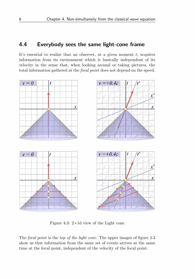
It’s essential to realize that an observer, at a given moment t, acquiresinformation from its environment which is basically independent of itsvelocity in the sense that, when looking around or taking pictures, thetotal information gathered at the focal point does not depend on the speed.
Figure 4.3: 2+1d view of the Light cone
The focal point is the top of the light cone. The upper images of figure 4.3show us that information from the same set of events arrives at the sametime at the focal point, independent of the velocity of the focal point.

4.4 Everybody sees the same light-cone frame 7
The ”frame” which we literally see is the light-cone frame. We neverdirectly see that what we intuitively call the now : the set all of eventswe define as happening at ”the same time”. We derive our space-timecoordinate system indirectly. We infer it from the way we see the light-cone frame.
Apparently the different ways of seeing the same set of events at the sametime leads us to constructing different rest frames and different coordinatesystems. Therefor, understanding the illusion of different reference framesamounts to understanding the different ways we see the light-cone frame.
Such differences amount to changes of the apparent angle of the rays com-ing from an object, changes of the apparent wavelength (color) of the lightform objects. However, the total information does not change.
We want to see what happens when our surrounding as a whole is accel-erated. Say we could take our world and the solar system and accelerateit to a billion kilometer per hour. We should be able to do so withoutperceiving any differences.
Why is it that our daily surrounding looks the same as ever, while at thesame time we infer that our coordinate system has become very differentcompared to the restframe? Why is the frame of simultaneity which weinfer from how we see the light-cone frame so different?
The bottom images of figure 4.3 relate events on the light-cone with pre-vious locations of the observer. The requirement of symmetry betweenevents at both sides leads us to connect events which are on the x′-axis inthe case of the moving observer. The trajectory of the moving observerlays in the middle of the selected events on the lightcone.
If we are to understand non-simultaneity as an emergent result of the waveequations, then we need to explain the mechanism which causes the movingobserver to infer that these events are simultaneous events.
In the previous section we did see from figure 4.2 that the notion of simul-taneity is inferred from the simultaneous arrival of light from equidistantevents. Equidistance is inferred when equally sized objects have the sameangular size in the viewing field and are therefor projected with the samesize on a photograph or on our vision. The further assumption of anisotropic speed of light then allows us to define the complete set of allsimultaneous events.

8 Chapter 4. Non-simultaneity from the classical wave equation
4.5 Passengers in rows and atoms in rows
The simplest configuration to study in different reference frames is possiblyan array of equally spaced identical objects. In the case of atoms in alattice structure one can study the required equilibrium of force betweendirect neighbors. The example of rows of passengers is useful to study whythe passengers accelerated to ultra relativistic velocities do not notice anyvelocity dependent effects whatsoever when looking around inside theircabin.
Figure 4.4: passengers in a row
Figure 4.4 shows the cabin at rest on the left side. Light coming from eitherthe front passenger or the passenger at the back takes the same time toreach the passenger in the middle. If the passenger in the middle wouldtake a 360o degrees panorama picture then it would show an equally sizedfront seat and back seat passenger. (In our example we use ”identical”passengers just for simplicity).
The right hand side of same figure shows a very fast forward moving cabin.Light from the front passenger reaches the middle passenger much fasterwith a relative speed of c+ v, while the light from the back passenger goesrelatively slower with c− v. A 360o picture taken by the middle passengerat a certain time t would combine a nearby front seat passenger with afurther away back seat passenger.

4.6 The velocity dependent viewing angle 9
4.6 The velocity dependent viewing angle
At first glance one might expect that the picture would show a larger frontseat passenger and a smaller back seat passenger. This because the ”lightray cone” from the front seat passenger has a wider spatial angle as theone from the passenger in the back seat.
However, special relativity tells us of course that both passengers shouldhave the same size on the picture: Physics is reference frame independent.Now how then does this work? Clearly there must be a counter effectwhich makes the nearby objects in the front look smaller and the objectsat back look bigger.
Figure 4.5: Velocity dependent apparent size
The effect is compensated because objects also look larger or smaller, de-pending on the speed, as the result of another effect: The relative spatialangle under which the rays propagates appears larger or smaller dependingon the velocity. The different absolute angles in figure 4.4 will appear thesame because the moving observers see different angles.
A situation which can’t hardly be more every-day-like is that of the showerin figure 4.5. If we decent bending our knees then the apparent angle ofthe droplets becomes wider. If we would decent at the same speed as thedroplets fall then we would see the droplets moving horizontally away fromus in all directions. The angle would be 180o in this case.
10 Chapter 4. Non-simultaneity from the classical wave equation
4.7 Simultaneity and the invariance of size
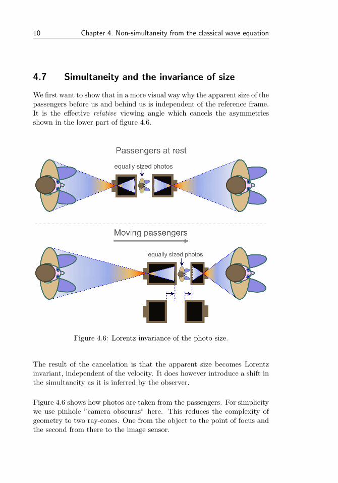
We first want to show that in a more visual way why the apparent size of thepassengers before us and behind us is independent of the reference frame.It is the effective relative viewing angle which cancels the asymmetriesshown in the lower part of figure 4.6.
Figure 4.6: Lorentz invariance of the photo size.
The result of the cancelation is that the apparent size becomes Lorentzinvariant, independent of the velocity. It does however introduce a shift inthe simultaneity as it is inferred by the observer.
Figure 4.6 shows how photos are taken from the passengers. For simplicitywe use pinhole ”camera obscuras” here. This reduces the complexity ofgeometry to two ray-cones. One from the object to the point of focus andthe second from there to the image sensor.

4.7 Simultaneity and the invariance of size 11
The light rays from the passenger at the back takes more time to reachthe moving camera compared to the light rays from the passenger in front.The photos turn out equal in size (Lorentz invariant) in spite of what thedifferent absolute viewing angles of the ray-cones would suggest.
The photos end up equal because the length of the ray-cones inside thecameras is also asymmetric. The image sensor moves away or towards therays after the focal point is passed.
Figure 4.7: Taking a photograph while moving, step by step.
Figure 4.6 shows the starting point of the rays at the passengers, and theend point of the arrays in the camera obscura. These start and end eventshappen at different times while the passengers and the camera are movingin the mean time .
In figure 4.7 we aim to visualize this step by step. The propagation ofthe light front from the passenger towards the image sensor is numberedfrom 0 through 5. The ray cone angles shown are the relative angles. Atthe rightmost site of figure 4.7 we combine all the intermediate wavefrontstogether and see how they define the absolute ray-cone angle in figure 4.6.

12 Chapter 4. Non-simultaneity from the classical wave equation
4.8 The relative versus the absolute viewing angle
The absolute viewing angle ϕabs as shown in figure 4.8 is defined by thepaths of the light rays to the final position of the observer. The relativeviewing angle ϕrel is based on the relative positions of the observer withregard to the object he is viewing.
Figure 4.8: The relative angle ϕrel versus the absolute angle ϕabs
From the intermediate steps we see that the moving passenger sees thelight from the object approaching him under the relative angle and notunder the absolute angle. The relative viewing angles of the ray-cones ofthe passenger in front him and the passenger behind him are the same,while the absolute viewing angles differ.
The observer assumes from the identical sizes (identical relative viewingangles) that both passengers are at equal distances away from him. Fur-thermore, from the identical sizes and the equal distances he assumes thatthe rays were emitted at the same time. Hereby he defines a differentnotion of simultaneity. A simultaneity which is different from that of theobserver at rest.

4.8 The relative versus the absolute viewing angle 13
Note that the naive observer bases his notion of simultaneity on the obser-vation that events occur at the same time while the more educated observerwill also consider the time delay of the propagation.
However, he assumes that equal objects at equal distances have the samesize, and so he will conclude that the light rays took an equal amount oftime to reach him, and consequently, that the speed of light is Lorentzinvariant and always equal to c.
Figure 4.9: Light cone frames of passengers at rest and moving
The difference of simultaneity is the result of the difference in start times ofthe light rays towards the moving observer . Figure 4.9 show the Minkowskidiagrams associated with the situations at rest and moving.
The light-cones are the same in both cases. The arrows show the pathsin space-time of the passengers at rest and moving. The crossings of thex-axis and x’-axis mark the events from which the light rays reach theobserver in the middle at the at the same time.
From this we can conclude: the x-axis and x’-axis define the planes of si-multaneity for the observer at rest and the observer in motion respectively.
14 Chapter 4. Non-simultaneity from the classical wave equation
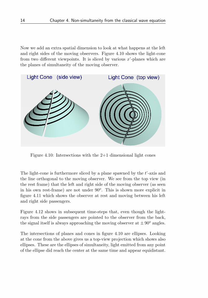
Now we add an extra spatial dimension to look at what happens at the leftand right sides of the moving observers. Figure 4.10 shows the light-conefrom two different viewpoints. It is sliced by various x’-planes which arethe planes of simultaneity of the moving observer.
Figure 4.10: Intersections with the 2+1 dimensional light cones
The light-cone is furthermore sliced by a plane spawned by the t’-axis andthe line orthogonal to the moving observer. We see from the top view (inthe rest frame) that the left and right side of the moving observer (as seenin his own rest-frame) are not under 90o. This is shown more explicit infigure 4.11 which shows the observer at rest and moving between his leftand right side passengers.
Figure 4.12 shows in subsequent time-steps that, even though the light-rays from the side passengers are pointed to the observer from the back,the signal itself is always approaching the moving observer at ± 90o angles.
The intersections of planes and cones in figure 4.10 are ellipses. Lookingat the cone from the above gives us a top-view projection which shows alsoellipses. These are the ellipses of simultaneity, light emitted from any pointof the ellipse did reach the center at the same time and appear equidistant.

4.8 The relative versus the absolute viewing angle 15
Light rays at 90o angles in the passengers restframe.
Figure 4.11: Absolute angles of the light rays from side passengers
Figure 4.12: light rays from side passengers, step by step
16 Chapter 4. Non-simultaneity from the classical wave equation
4.9 The ellipsoids of simultaneity
Having spend an unusual long time on visualizations we’ll now spend sometime to fill in some of the elementary mathematical properties.
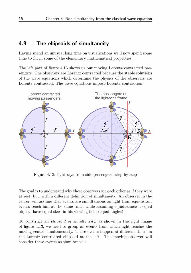
The left part of figure 4.13 shows us our moving Lorentz contracted pas-sengers. The observers are Lorentz contracted because the stable solutionsof the wave equations which determine the physics of the observers areLorentz contracted. The wave equations impose Lorentz contraction.
Figure 4.13: light rays from side passengers, step by step
The goal is to understand why these observers see each other as if they wereat rest, but, with a different definition of simultaneity. An observer in thecenter will assume that events are simultaneous as light from equidistantevents reach him at the same time, while assuming equidistance if equalobjects have equal sizes in his viewing field (equal angles)
To construct an ellipsoid of simultaneity, as shown in the right imageof figure 4.13, we need to group all events from which light reaches themoving center simultaneously. These events happen at different times onthe Lorentz contracted ellipsoid at the left. The moving observer willconsider these events as simultaneous.

4.9 The ellipsoids of simultaneity 17
The two propagation times shown on the x-axis of the ellipsoid of simul-taneity in figure 4.13 follow from the relative speeds of the light towardsthe observer at focal point F1, which are 1 − β and 1 + β. The time de-lay from the passengers at the sides is determined by the relative velocity√
1− β2 by which the vertical distance is reduced as light from the sidepassengers propagates to the moving observer as shown in figure 4.12.
Figure 4.14: Some more properties of the ellipsoid of simultaneity
Figure 4.14 shows some more basic properties which follow from the as-sumption that the closed curves are ellipses and thus are described by.(
x− βtγτ
)2
+(
y
τ
)2
= 1 (4.9)
Where γτ is the length of the major axis and τ is the length of the minoraxis of the ellipses. The assumption of ellipses is by no means obvious and

18 Chapter 4. Non-simultaneity from the classical wave equation
in section 4.13 we derive that this is true only in case of a Lorentz con-traction by exactly a factor of γ.
We turn to figure 4.15 for some further elementary calculations. It doesalso correspond with the light-cone top view of figure 4.10. The ellipsesare the intersections of the x’-planes of simultaneity with the light-cone.
Figure 4.15: Angular sizes for a velocity β
We obtain the parametric expressions of the ellipses by intersecting thelightcone with the planes of constant t′.
The lightcone: t = −1c
√x2 + y2 (4.10)
The planes: t′ = γ
(t− v
c2x
)(4.11)

4.9 The ellipsoids of simultaneity 19
Setting c = 1 as we have done until now and exchanging t′ with t at the lefthand side of the latter expression so that we can equate the two expressionsas t = fcone = fplane and we obtain the second order parametric equationfor the ellipses.
The ellipses:(x− βγt′
γt′
)2
+(
y
t′
)2
= 1 (4.12)
The proper time t′ of the observer determines the ellipsoid. This meansthat the ellipsoids represent simultaneous events for the moving observer.The outer ellipse corresponds with proper time t′ = 1.
The time T(ϕ) in figure 4.15 denotes the time it takes for light to propagatefrom the (outer) ellipse to the top of the light cone. We determine theintersection point of the radial line y = (tanϕ)x with the (outer) ellipseand obtain for the x and y coordinates and the propagation time T.
x = γ
[1− β2
1 + β cosϕ
]cosϕ y = γ
[1− β2
1 + β cosϕ
]sinϕ (4.13)
Propagation time: T(ϕ) = γ1− β2
1 + β cosϕ(4.14)
Some special values of T at angles ϕ = 0 and ϕ = π on the x-axis are.
T(0) = γ(1− β) T(π) = γ(1 + β) (4.15)
While on the y-axis where ϕ = π/2 and ϕ = −π/2 radians we find.
T(π/2) = T(−π/2) = γ(1− β2) = γ−1 (4.16)
The angle under which the light approaches from the side as seen in therest frame of the passenger and as visualized in figures 4.11 and 4.12 isfound by requiring T=γ and is given by.
ϕ⊥ = arccos(−β) (4.17)

20 Chapter 4. Non-simultaneity from the classical wave equation
4.10 From ellipsoids to spheres of simultaneity
( The Lorentz transform )
We found that an ellipsoid of simultaneity of a moving observer is anintersection between the light cone and a ”plane”of simultaneity like infigure 4.10. Such a ellipsoid of simultaneity is seen as a symmetric sphereof simultaneity for the moving observer.
All the events on the ellipsoid reach the moving observer at the same time,and equal objects at these events seem equidistant for the observer. Theyseem to have equal sizes because their relative viewing angles look equal.
The transformation between the ellipsoid and the sphere of simultaneity isof course the Lorentz transform which will be subject to a more detailedinspection here from this perspective. We can separate the transform intotwo distinct steps.
1. Transformation from absolute to relative coordinates. (from absoluteviewing angles to relative viewing angles), See also section 4.11
2. Corrections due to the Lorentz contraction and Time dilation of themoving observer, See also section 4.12
Figure 4.16 visualizes the Lorentz transform of the spatial component xfrom ellipsoid to sphere. The x used for the ellipsoid is just the same x asfor the rest frame. The events on the ellipsoid do belong to different timesbut the positions are just the x-positions.
The first step is the transform to the relative positions of the events withregard to the observer. The focus (top of the light cone) continues to moveduring the time T required for the time it takes for light to propagate fromthe event to the focus. We have to correct the x coordinate accordingly.
x′′ = (x− βt) (4.18)
The second step is a correction by γ because, as we will discuss in sec-tion 4.12, a Lorentz contracted observer will observe his environment asstretched by a factor gamma instead.
x′ = γ x′′ = γ(x− βt) (4.19)

4.10 From ellipsoids to spheres of simultaneity 21
With this expression we have arrived at the standard form of the Lorentztransform for the spatial coordinate.
Lorentz transform of the spatial components in two steps
Figure 4.16: Lorentz transform (space components)

22 Chapter 4. Non-simultaneity from the classical wave equation
Lorentz transform of the time component
Figure 4.17 shows the same two steps as the previous image but now look-ing from the top and also looking from the side of the light cone. The lattershows us the time axis t of which we will discuss the Lorentz transform.
Our goal is to define the time t′ as it is experienced by the moving observer.We first have to redefine simultaneity in correspondence with the assump-tions of the moving observer, who considers equidistant events from whichlight rays reach him at the same time as simultaneously.
We see from figure 4.17 that these planes of simultaneous events are nothorizontal but that t′ is dependent on x. We have to include this depen-dency in the transform. The ramp is βx for the ellipsoids of simultaneity,so in this case we could define (just as an example) t′′′ = t− βx.
However, our starting point is figure 4.17b which shows us the situation asseen by a moving observer if he would not be Lorentz contracted nor subjectto time dilation. It shows the relative positions of the events with regardto the observer at the moment they happened. The ramp depending onthe x′′-coordinate here is steeper by a factor γ2 since the relative-position-ellipsoid is shorter by a factor γ2. This gives us.
t′′ = t− βγ2 x′′
= t− βγ2(x− βt)= γ2
(t− βx
) (4.20)
Going from figure 4.17b to 4.17c we need to compensate for the two effectswhich modify the observations of the moving observer. We have to increasethe spatial dimension in the x-direction by γ because this direction appearsstretched for the Lorentz contracted observer. Next we have to decreasethe time by a factor γ because of the time dilation which the movingobserver experiences.
t′ = t′′/γ = γ (t− βx) (4.21)
We have recovered the standard Lorentz transform. We have gone from theellipsoids of simultaneity for the moving observer as seen in the rest frame,to the symmetric spheres of simultaneity as experienced by the observer.

4.10 From ellipsoids to spheres of simultaneity 23
Lorentz transform of the time component in two steps
Figure 4.17: Lorentz transform (time component)

24 Chapter 4. Non-simultaneity from the classical wave equation
4.11 Step 1: From absolute to relative positions
( From absolute viewing angles to relative viewing angles )
Figure 4.18 shows the ellipsoids of simultaneity with absolute positions(left) and relative positions (right) with regards to the moving focal point.Intermediate positions 1 through 5 of the moving focal point correspondwith the moments at which the events occur on the ellipsoid.
We obtain the relative positions if we hold the position of the focal pointfixed. The ellipsoid with absolute positions is stretched by γ while theellipsoid with relative positions is Lorentz contracted by γ.
Figure 4.18: The ellipsoids of simultaneity with absolute/relative positions
We can understand the Lorentz contracted ellipsoid of simultaneity at theright side as follows: Imagine filming a moving sphere which is Lorentzcontracted accordingly. We keep the center fixed. Next we start freezingvertical stripes of the image, starting at the left and going to the right.
By freezing the stripes we capture events on the ellipsoid at different times.The size and shape of the resulting ellipsoid is the same but what wehave done is introducing a different simultaneity: The simultaneity of themoving observer in his rest frame.

4.11 Step 1: From absolute to relative positions 25
This part of the Lorentz transform is just a simple Euclidian transformationas shown in figure 4.19. The x-coordinate is shifted with the velocity β.
x′′ = (x− βt) (4.22)
The transformation to relative positions also gives us the relative viewingangles. The trajectory ` in figure 4.19 shows the absolute viewing anglewhile the trajectory `′′ shows the relative viewing angle.
Figure 4.19: From absolute positions (angles) to relative positions (angles)
The two trajectories ~̀ and ~̀′′ are thus related by a simple vector addition.The relative viewing angle is the angle as seen by a non-Lorentz compressedobserver. The relative viewing angles are not yet spherically symmetric asthey should be for the equidistance requirement. The second part of theLorentz transform which compensates for the Lorentz compressed state ofthe observer will give rise to a spherically symmetric result.

26 Chapter 4. Non-simultaneity from the classical wave equation
4.12 Step 2: Viewing while Lorentz contracted
Here we ask ourself how we would see our world if everything is scaled inone particular direction by a certain factor. Would we notice this or wouldwe simply not see this? It’s much easer to be convinced that we would notnotice a scaling in all directions with the same factor, but what mechanismcould prevent us to see such a unidirectional scaling as required for Lorentzinvariance?
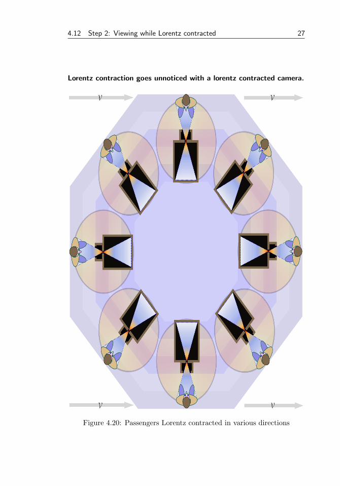
Figure (4.20) is intended to visualize this. It shows our passengers Lorentzcontracted under various angles relative to the velocity. We use again thecamera obscura as the simplest example of a camera and this time we usean over-sized version for clarity. For a moment we won’t bother with thepropagation times of the light ray for a first conclusion.
Technically, that what we see is equal under different conditions if the samerays always hit the same receptors of the eye (or the image sensor). Thesame nerve cells in the brain are activated (and the same file is constructedin a digital camera). We see in figure (4.20) that this indeed seems to bethe case for our camera obscura.
For the next step we need to consider the time delays in ray propagation.Figure (4.20) has recorded events over the time it takes the light raysto move from the passengers, via the focus, to the screen of the cameraobscura. All rays are at the focus points at the same time. A focus pointis the top of the light-cone as in figure (4.17b) and it’s also the bottom ofthe light cone of the rays going to the screen.
Figure (4.20) shows a Lorentz compressed image because all events arerecorded relative to the position of the moving at the time the event occurs.We translate along with the moving focus during the recording keeping itfixed. Since the positions are Lorentz contracted at each moment we addan event we get an image representing the entire recording which is Lorentzcompressed as well.
Conclusion:An observer at the focus would assume that all events are simultaneousbecause, firstly: the light rays reach him simultaneously, and secondly:he assumes that the events are equidistant because the size of our modelpassenger is the same independent of the direction. (see section 4.3). Themoving observer concludes that his notion of simultaneity is different.
4.12 Step 2: Viewing while Lorentz contracted 27
Lorentz contraction goes unnoticed with a lorentz contracted camera.
Figure 4.20: Passengers Lorentz contracted in various directions
28 Chapter 4. Non-simultaneity from the classical wave equation
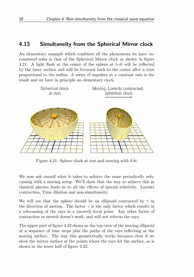
4.13 Simultaneity from the Spherical Mirror clock
An elementary example which combines all the phenomena we have en-countered sofar is that of the Spherical Mirror clock as shown in figure4.21. A light flash at the center of the sphere at t=0 will be reflectedby the inner surface and will be focussed back to the center after a timeproportional to the radius. A series of impulses at a constant rate is theresult and we have in principle an elementary clock.
Figure 4.21: Sphere clock at rest and moving with 0.8c
We now ask ourself what it takes to achieve the same periodically refo-cussing with a moving setup. We’ll show that the way to achieve this inclassical physics leads us to all the effects of special relativity. Lorentzcontraction, Time dilation and non-simultaneity.
We will see that the sphere should be an ellipsoid contracted by γ inthe direction of motion. The factor γ is the only factor which results ina refocussing of the rays in a (moved) focal point. Any other factor ofcontraction or stretch doesn’t work, and will not refocus the rays.
The upper part of figure 4.22 shows us the top-view of the moving ellipsoidat a sequence of time steps plus the paths of the rays reflecting at themoving surface. The way this geometrically works becomes clear if weshow the mirror surface at the points where the rays hit the surface, as isshown in the lower half of figure 4.22.

4.13 Simultaneity from the Spherical Mirror clock 29
The resulting object is another ellipse, which is now stretched (instead ofcontracted) by a factor γ. The shape has to be an ellipse because of thecharacteristic two focal points of ellipses plus the rule that any path withone reflection between the two focal points is equally long.
Figure 4.22: Moving (Lorentz contracted) sphere clock at 0.8c
These two properties of ellipses guarantee that the rays are refocussed, notonly at the same point but at the same time as well. The stretch factorγ causes a slowdown of the tick rate of our elementary clock: We haverecovered the time dilation factor γ.
30 Chapter 4. Non-simultaneity from the classical wave equation
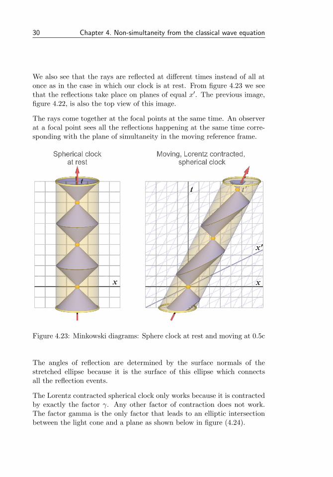
We also see that the rays are reflected at different times instead of all atonce as in the case in which our clock is at rest. From figure 4.23 we seethat the reflections take place on planes of equal x′. The previous image,figure 4.22, is also the top view of this image.
The rays come together at the focal points at the same time. An observerat a focal point sees all the reflections happening at the same time corre-sponding with the plane of simultaneity in the moving reference frame.
Figure 4.23: Minkowski diagrams: Sphere clock at rest and moving at 0.5c
The angles of reflection are determined by the surface normals of thestretched ellipse because it is the surface of this ellipse which connectsall the reflection events.
The Lorentz contracted spherical clock only works because it is contractedby exactly the factor γ. Any other factor of contraction does not work.The factor gamma is the only factor that leads to an elliptic intersectionbetween the light cone and a plane as shown below in figure (4.24).

4.13 Simultaneity from the Spherical Mirror clock 31
Any other factor of contraction leads to a non-elliptic curve. If we startwith a spherical clock and contract it by ′a′ instead of γ as in figure (4.24)then the relation between x and y is given by the quadratic expression.
a2x2 + y2 = 1 (4.23)
When the center C of the Lorentz contracted ellipse is at focus point F1,then the light ray starts in the direction of reflection point p(x, y). Figure(4.24) shows the location of the center C at the moment of reflection. Thecenter of the ellipse then continues to move with a velocity β during thetime t which the reflected ray needs to propagate to the focus point F2.
Figure 4.24: Direct calculation of the lightcone ellipse (v=0.866c)
The time t is obtained by solving the resulting equation in t and given by.
t = βγ2x− γ√
1 + (γ2 − a2)x2 (4.24)
xf = γ2x− βγ√
1 + (γ2 − a2)x2 (4.25)
With t known we can calculate the coordinate xf=x+ βt of the reflectionpoint p(x, y) relative to the focus F2. We do find the expected stretch bya factor of γ2 but also an unwanted term with a non-linear dependency onx which is canceled only if the Lorentz contraction factor ’a’ is equal to γ.

32 Chapter 4. Non-simultaneity from the classical wave equation
4.14 Reversal of Lorentz contraction
Understanding the mechanism of how and why we perceive different si-multaneities in different reference frames has been the primary purpose ofthis introductory chapter. A short review is now given of how, as a result,the physical effect of Lorentz transform is reversed when going from oneto another reference frame.
Lorentz contraction is a physical effect, it is a property of the stable, mov-ing solutions of the elementary wave-equations for both electro-magnetismand particles with mass. Lorentz contraction is a physical effect on it’s own,next to time dilation and simultaneity. It is not caused by non-simultaneity.It is the reversal of the effect which is caused by non-simultaneity.
Figure 4.25 shows all there to know. The upper half shows a moving trainwith a proper length of L which is physically Lorentz contracted to L/γ.It shows the trajectories t′ of the moving train and how it intersects withthe plane of simultaneity x′ of the moving observer.
The begin-to-end length of this intersection is stretched by a factor γ2 toa length of γL on the x-axis. (This factor γ2 = 1 + β2 + β4 + β6... can bechecked with a simple geometric trick which is also shown in the image)
This length of γL is first scaled down again by a factor γ2 when we per-form the Euclidian transformation x′′ = x − βt as shown in section 4.11,and secondly, when we take the effect of the Lorentz contraction on theobservation into account, it is stretched by a factor γ in the direction ofmotion, as shown in section 4.12.
This leads to an effective length of L as seen by the moving Lorentz con-tracted observer. The moving observer sees himself and the length of thetrain in which he travels in a way which is independent of his velocity asrequired by the invariance of physics under boosts.
The lower part of figure 4.25 shows the reversed case. The train at resthas a length L, a factor γ longer as the moving train.
The intersection of the trajectories t of the train at rest with the plane ofsimultaneity x′ is L as well on the x-axis. This now is a factor of γ shorteras the intersection of the moving train which we found to be γL. Thismeans that the Lorentz contraction is reversed in the moving frame.

4.14 Reversal of Lorentz contraction 33
Reversal of the Lorentz contraction demonstrated with trains
Figure 4.25: Reversal of the Lorentz contraction
34 Chapter 4. Non-simultaneity from the classical wave equation
4.15 Reversal of Time dilation
Time dilation is, like Lorentz contraction, a physical effect. It is caused bythe longer signal paths in the stable, moving solutions of the elementarywave equations of electro-magnetism and matter-waves.
We have seen from our bouncing photon clock examples that Time di-lation requires the effect of Lorentz contraction in order to be isotropic(independent of the direction in which photon bounces). It assures thatthe time it takes for the photon to bounce back and forward is the samein all directions.
It would not be possible to define a unique time dilation factor withoutsuch an isotropic definition. Only a Lorentz contraction by exactly a factorof γ allows us to formulate a unique definition of time dilation.
Time dilation is reversed by non-simultaneity via a redefinition of the planeof simultaneity x′. A redefinition of a coordinate system is in principle”non-physical”. Distant events are related in different ways depending oncoordinate systems chosen consistently in such a way that it is most naturalfor observers which are at rest in the associated reference frames.
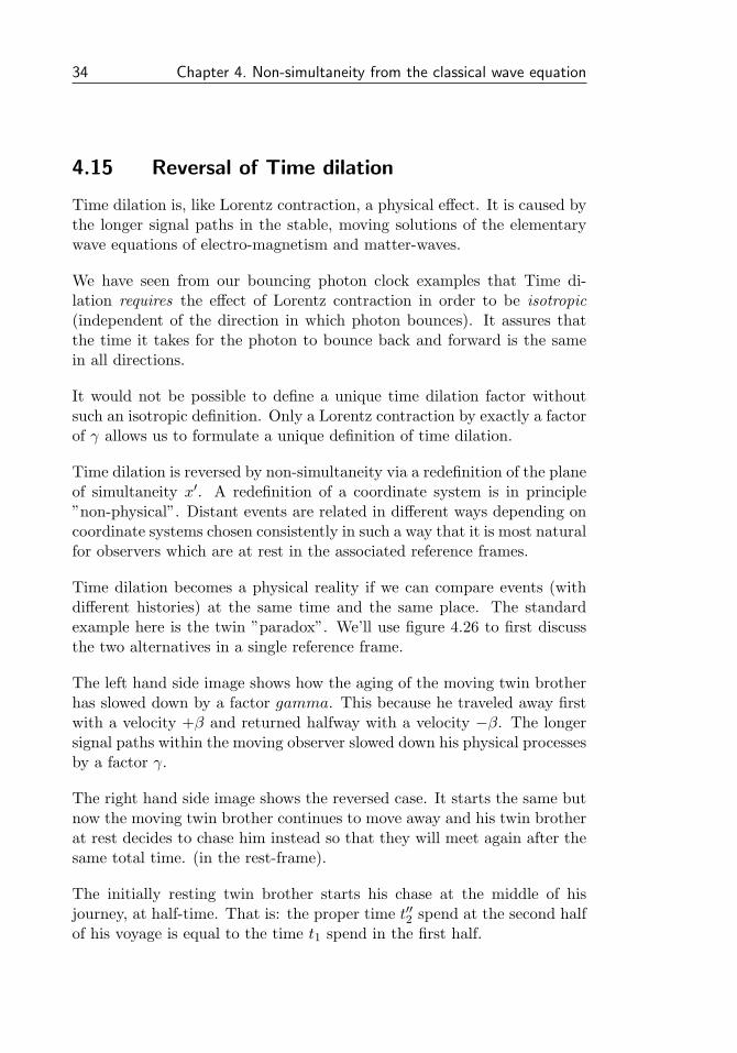
Time dilation becomes a physical reality if we can compare events (withdifferent histories) at the same time and the same place. The standardexample here is the twin ”paradox”. We’ll use figure 4.26 to first discussthe two alternatives in a single reference frame.
The left hand side image shows how the aging of the moving twin brotherhas slowed down by a factor gamma. This because he traveled away firstwith a velocity +β and returned halfway with a velocity −β. The longersignal paths within the moving observer slowed down his physical processesby a factor γ.
The right hand side image shows the reversed case. It starts the same butnow the moving twin brother continues to move away and his twin brotherat rest decides to chase him instead so that they will meet again after thesame total time. (in the rest-frame).
The initially resting twin brother starts his chase at the middle of hisjourney, at half-time. That is: the proper time t′′2 spend at the second halfof his voyage is equal to the time t1 spend in the first half.

4.15 Reversal of Time dilation 35
Reversal of the Time dilation demonstrated with the twin voyages
Figure 4.26: Reversal of the Time dilation
The physical time dilation during the second part of his voyage is suchthat the total proper time of the path t′′2 + t1 is less by a factor γ2 due tothis higher time dilation. This is a factor γ less as his twin brother whohas traveled with continues velocity +β during his entire voyage2
The twin brother who accelerated halfway to catch up with his brother hasaged less by a factor γ compared with his non-accelerating twin-brother.
2The mathematics of this was handled in the previous chapter, in section 3.3

36 Chapter 4. Non-simultaneity from the classical wave equation
For sofar we have only looked at a single reference frame, but we havenevertheless seen how the non-accelerating twin brother ages less by atime dilation factor γ. This factor is entirely explained physically by thelonger path-lengths of signals within moving observers.
During all this we never needed to refer to non-simultaneity and non-simultaneity is as such not required to explain the two cases. It did show upindirectly however. The half-time points of the two travelers in the right-side image are not simultaneous in the rest-frame but they are simultaneousin the moving frame instead, they are on the same x′-axis.
Simultaneity and the reversal of time dilation
The reversion, required by he invariance of physics under boosts, says thatboth brothers, at any moment of time, can say that his twin brother is agingslower as himself by a factor γ. This is possible only by a redefinition ofsimultaneity, a redefinition in such a way that their notion of simultaneitycorresponds most naturally to what they observe.
Basically, an observer will assume that two equidistant events are simul-taneous if the light-rays of both events reach him at the same time and hejudges equidistance by the observation that identical objects at the eventshave equal viewing angles.
Figure 4.26 shows, at the left side, the two different reference frames ofthe accelerating observer. In the first of these frames the twin brother atrest ages by a time t1. The acceleration halfway then skips a time Ta afterwhich the passenger at rest ages by time t2. Now the total time t1 + t2is a factor γ less as the proper time spend by the moving observer. Themoving observer may claim that his twin-brother at rest was aging slowerby a factor γ.
So both twin brothers can claim that the other is aging less by a factorγ. Both are correct in the coordinate systems they use. The difference isthe acceleration and the time Ta which is skipped. The twin brother atrest ages with the total time t1 + Ta + t2 which is a factor γ higher as theproper time by which the moving twin brother aged.

4.15 Reversal of Time dilation 37
So we have the following proper traveling times for the left hand side offigure 4.26:
t′1 + t′2 = γ(t1 + t2
)(4.26)
t1 + Ta + t2 = γ(t′1 + t′2
)(4.27)
A redefinition of the coordinate system is in principle a non-physical op-eration. It merely adapts, reorders, the description of the environment ina way which is most natural to the moving observer.
One can for instance say that the observer at rest ”ages” by a time Taduring the acceleration of the traveling observer. This is not incorrect butit is non-physical because we are only dealing with a redefinition of thereference frame during the acceleration.
Figure 4.26 shows the same effect on the right hand side for the case ofthe twin brother at rest who decides to chase his non-returning travelingtwin brother. The twin brother which accelerates has again basically twodifferent reference frames during the two different stages of his voyage.
The chasing twin-brother can claim during the first stage that his twinbrother ages less since t1 = γt′3. He can also claim this during the secondstage of his voyage because t′′2 = γt′4. The acceleration at half-time againskips a time Ta due to the redefinition of his coordinate system. Thisskipped time Ta corresponds with a skipped proper time of T′a = Ta/γ inthe reference frame of his non-accelerating brother.
This gives us the following relations for the proper traveling times on theright hand side of figure 4.26:
t1 + t′′2 = γ(t′3 + t′4
)(4.28)
t′3 + T′a + t′4 = γ(t1 + t′′2
)(4.29)
Again, both brother may claim that the other is aging less by a factor γ,and they may claim so due to the redefinition of their coordinate systems.

38 Chapter 4. Non-simultaneity from the classical wave equation
4.16 Simultaneity from Huygens principle
The Huygens principle, in its most elementary form, states that the lightwave front is always in the direction of the propagation. All but few effectsin optical geometry can be explained via this simple statement.
Huygens principle plays an equally important role in matter waves, againthe propagation direction and the wavefront direction are always aligned.
Figure 4.27: Huygens principle
Interference plays an elementary role in the physics of propagation and thewave front represents the lines along which the phase is added maximallyor minimally.
If physics is to remain invariant under boosts then we should expect thatHuygens principle is equally well valid in all other reference frames. Thisnow leads to the requirement of non-simultaneity. As the vectors of motionchange in direction going from one reference frame to another, so shouldthe wavefront direction change.

4.17 Simultaneity and the light wavefront direction 39
4.17 Simultaneity and the light wavefront direction
The requirement that the wavefront of electromagnetic radiation is alwaysoriented in the same direction as its velocity requires the introduction ofnon-simultaneity. The standard example of the bouncing photon clockshown left in figure 4.28 is Lorentz transformed to the middle image show-ing the wavefront rotated to the transformed direction of propagation.Such a rotation can only be obtained if t′ depends on the x-coordinate.
Figure 4.28: The bouncing photon clock moving vertically
An alternative transformation which lacks the non-simultaneity is the Man-souri Sexl transform shown at the right. The Mansouri Sexl transform’sexpression for t′ is the proper time of moving observer. The proper timeis obtained by setting x′ to zero after first substituting x with the inverseLorentz transform.
t′ = γ(t− βx) = γ(t− βγ(x′ + βt′)) (4.30)
x′ ≡ 0 =⇒ (1 + β2γ2)t′ = γt =⇒ t′ = t/γ (4.31)
The Mansouri Sexl transformation introduces Lorentz contraction and timedilation as required by special relativity. However, the missing ingredientin this transformation is non-simultaneity. No wave-front rotation occurs.

40 Chapter 4. Non-simultaneity from the classical wave equation
The wavefront rotation of light due to non-simultaneity
We want to have a closer look at the mechanism by which non-simultaneityleads to a rotation of the light wave-front. Figure 4.29 shows the verticaltiming bands with the ∆t resulting from non-simultaneity. The phase ofwavefront has propagated further in bands positive ∆t and it has propa-gated less in bands with negative ∆t. The result as we can see is a rotationof the light wave front.
Figure 4.29: Wave front rotation from non-simultaneity (for light)
Any rotation operation can always be decomposed into two orthogonalskew operations, which can be symbolically expressed as.
= � + ↓↑
Wavefront Rotation = Mansouri Sexl + Non Simultaneity
The first skew operation occurs with the Mansouri Sexl transform as shownin figure 4.28. The second skew operation is a result of non simultaneityas it is shown above in figure 4.29. Together they rotate the wavefront tothe new direction of motion in the new reference frame.
4.17 Simultaneity and the light wavefront direction 41
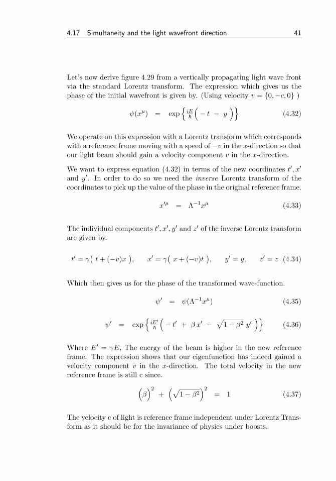
Let’s now derive figure 4.29 from a vertically propagating light wave frontvia the standard Lorentz transform. The expression which gives us thephase of the initial wavefront is given by. (Using velocity v = {0,−c, 0} )
ψ(xµ) = exp{iE~
(− t − y
)}(4.32)
We operate on this expression with a Lorentz transform which correspondswith a reference frame moving with a speed of −v in the x-direction so thatour light beam should gain a velocity component v in the x-direction.
We want to express equation (4.32) in terms of the new coordinates t′, x′
and y′. In order to do so we need the inverse Lorentz transform of thecoordinates to pick up the value of the phase in the original reference frame.
x′µ = Λ−1xµ (4.33)
The individual components t′, x′, y′ and z′ of the inverse Lorentz transformare given by.
t′ = γ(t+ (−v)x
), x′ = γ
(x+ (−v)t
), y′ = y, z′ = z (4.34)
Which then gives us for the phase of the transformed wave-function.
ψ′ = ψ(Λ−1xµ) (4.35)
ψ′ = exp{iE′
~
(− t′ + β x′ −
√1− β2 y′
)}(4.36)
Where E′ = γE, The energy of the beam is higher in the new referenceframe. The expression shows that our eigenfunction has indeed gained avelocity component v in the x-direction. The total velocity in the newreference frame is still c since.(
β)2
+(√
1− β2)2
= 1 (4.37)
The velocity c of light is reference frame independent under Lorentz Trans-form as it should be for the invariance of physics under boosts.

42 Chapter 4. Non-simultaneity from the classical wave equation
4.18 The wavefront rotation of matter waves
The rotation of the light wave front due to a difference in simultaneitycorresponds with objects which have a velocity of c. The direction of themotion is arbitrary but the velocity is fixed. Matter waves of particleswith mass can propagate with any velocity between zero and c. We expectthat the direction of the wave front corresponds with the direction of thevelocity of the particle just like in the case of electromagnetic radiation.
Figure 4.30: Wave front rotation from non-simultaneity (with mass m)
The change in direction is larger for slower moving particles when we gofrom one reference frame to another. We expect that the phase change dueto a different simultaneity needs to be larger to obtain a larger rotation ofthe wave front. This is indeed the case and shown in figure 4.30
∂2ψ
∂t2− c2∂
2ψ
∂x2− c2∂
2ψ
∂y2− c2∂
2ψ
∂z2= m2c4 (4.38)
The extra phase shift stems from the addition of a mass term m2c4 inthe wave equation which gives us the Klein Gordon equation. The eigenfunctions of this equation can be written in the same way as those of theelectromagnetic field,
ψ = exp{i~(− Et + pxx + pyy + pzz
)}(4.39)

4.18 The wavefront rotation of matter waves 43
but with an additional mass term leading to the classical relativistic energy-momentum relation for a particle with mass m.
E2 = p2xc
2 + p2yc
2 + p2zc
2 + m2c4 (4.40)
The mass term m is Lorentz invariant, it is the same in all reference frames.We can express ψ explicitly in terms of the velocity as follows.
ψ = exp{iE~c(− ct + vxx + vyy + vzz
)}(4.41)
To obtain figure 4.30 we start with a particle with mass moving in they-direction with a speed vy.
ψ = exp{iE~c(− ct + vyy
)}(4.42)
We perform a Lorentz transform corresponding with a speed of −vx so thatwe expect our particle to gain a velocity component vx in the x-direction.
t = γ(t′ + (−vx)x′
), and y = y′ (4.43)
We assume lower speeds so that we can approximate γ ≈ 1 and we obtain.
ψ = exp{iE~c(− ct′ + vxx′ + vyy′
)}(4.44)
This showns that our eigenfunction has indeed gained a velocity componentvx in the x-direction. For higher speeds it’s slightly less transparent as aresult of the relativistic speed addition rules. Note that the effect of wave-front rotation is essential at any speed, even at very low speeds.
The particles which build up our direct environment move at slow ”non-relativistic” speeds. Between quotes because it’s the relativistic effect ofnon-simultaneity which rotates the wave-fronts of the matter-waves so thatthey always point in the direction of the particle’s relative speed, the speedrelative to our own speed.

44 Chapter 4. Non-simultaneity from the classical wave equation
4.19 Negative energy waves and wavefront rotation
It is custom to associate anti-particles with negative values of E in ex-pression (4.39). Now what happens in this case with the direction of thewave front? It rotates the other way around! This does not correspondwith what we expect from the transformed motion of the particle, however,it’s correct when we assume that the particle was actually moving in theopposite direction.
Figure 4.31: Negative energy Wave front rotation.
This is shown in figure 4.31. We could expect this since the wave-frontactually propagate to the other direction because of the sign changes. Weget further confirmation if we construct a localized wave-packet with an(average) energy-momentum. The localized wave-packet as a whole doesalso propagate in the opposite direction.
It has been often stated in the Wheeler-Feynman tradition that negativeenergy anti-particles are moving ”backward in time” which would cor-respond with the reversion of the direction. Such a time-symmetry forelementary particles does not look totally unreasonable. Today however,when for instance anti-hydrogen is routinely produces with modern equip-ment, we do not really see a reversal of the arrow of time for anti-matterin terms of causality or the second law of thermodynamics.