Embed Size (px)
Citation preview

Chapter 4 Membrane Equipment

MEMBRANES
MODULES Membrane Housing
SYSTEMS Modules, Pumps, Piping, Tanks, Controls, Monitoring, Pretreatment Facilities, Cleaning Facilities
DESIGN & OPERATION Series/Parallel Tapered Cascade Continuous/Batch Crossflow/Dead End
The Components of Membrane Technology

- Module : the smallest unit into which the membrane area is packed. A number of modules are arranged together as a system. (single pass, recirculation, cascade system, etc.)
- Module configuration flat plate-and-frame module
Spiral-wound module
tubular tubular capillary hollow fiber
- The choice of module configuration as well as the module arrangements is based on : i) Type of separation problem
ii) Ease of cleaning, maintenance, operation iii) Compactness of the system iv) Possibility of membrane replacement
4-1. Introduction

Classification I : – Flat Sheet – Spiral Wound – Tubular – Capillary – Hollow Fibre
Membrane Modules
Classification II
- ‘Contained’ (Pressure Vessel) - ‘Submerged’ (or Immersed )
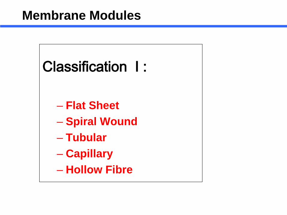
Classification I :
– Flat Sheet – Spiral Wound – Tubular – Capillary – Hollow Fibre
Membrane Modules
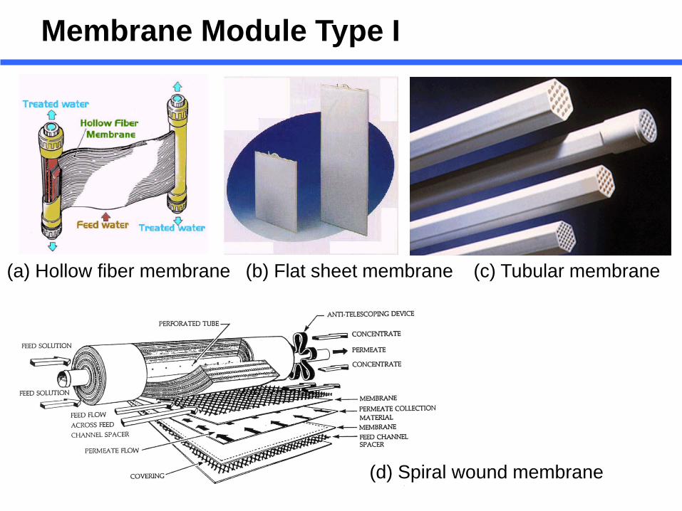
(a) Hollow fiber membrane (b) Flat sheet membrane (c) Tubular membrane
(d) Spiral wound membrane
Membrane Module Type I

Tubular type Plate & Frame type
Spiral Wound type Hollow fiber type
Membrane Module Type II
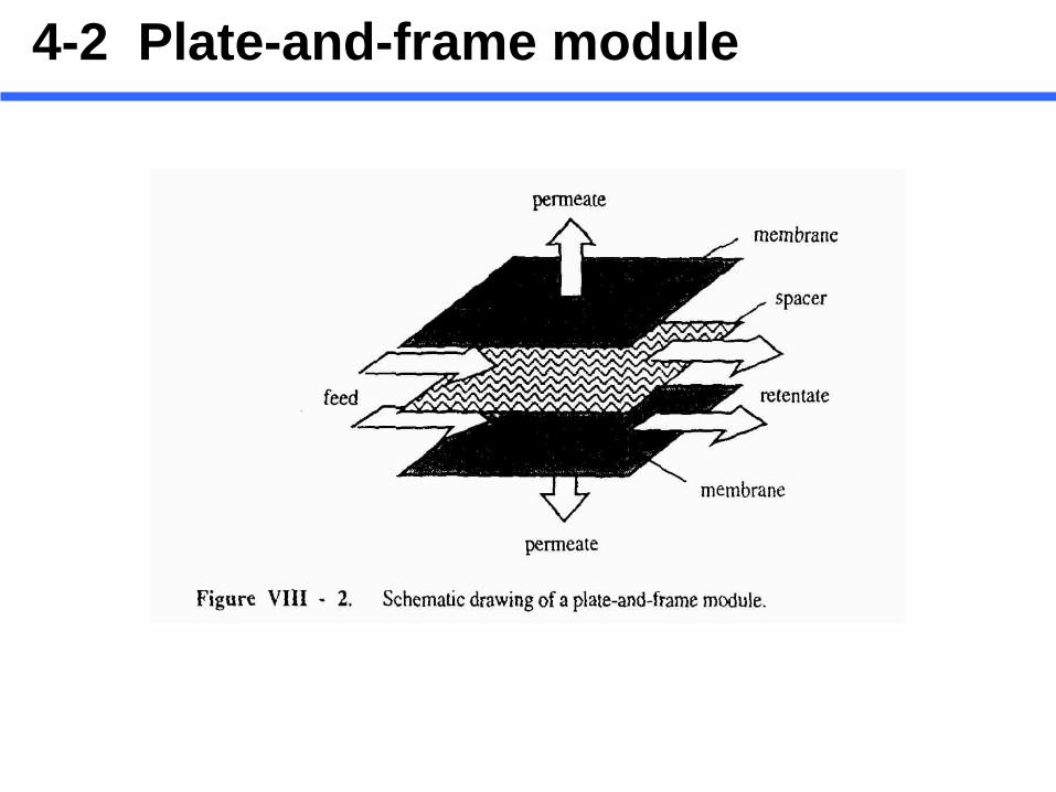
4-2 Plate-and-frame module

4-2 Plate-and-frame module

- Packing density ( membrane surface area per module volume ) : about 100-400 m2/m3
- “Stop disc” is introduced to reduce channeling and to establish an uniform flow distribution ( Fig. VII-3 ).
- Channel height : 0.5-1.0 mm ( DDS module )
- The permeate from each pair of membranes can be visually observed in the plastic tubing coming from each support plate.
Easy detection of leaks in a damaged membrane pair Sample analysis
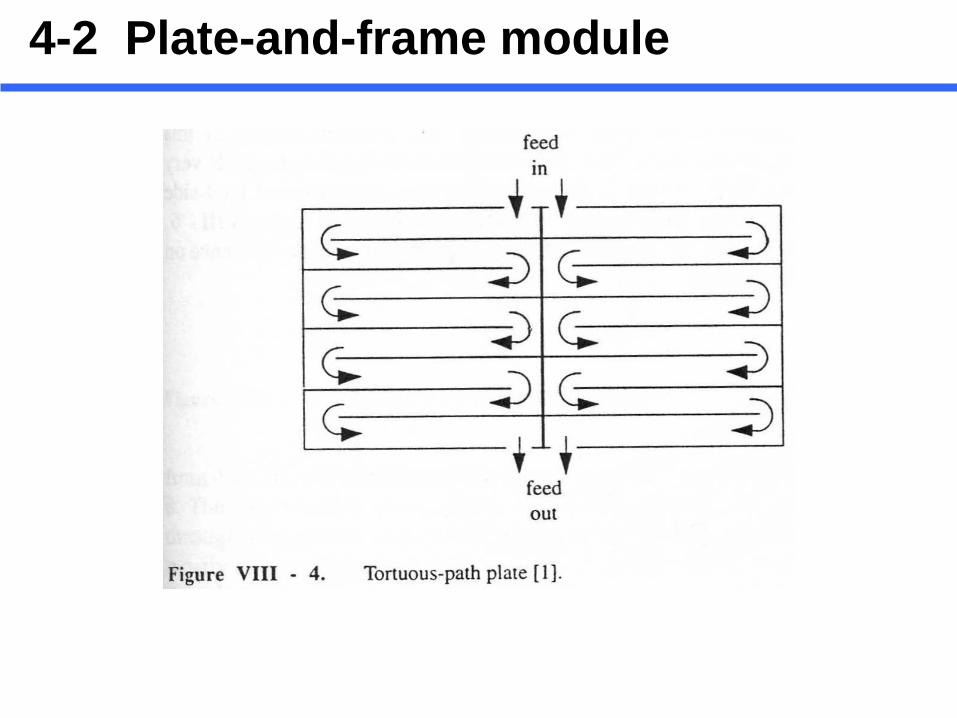
Flux measurement as a function of stack length - A gasket is used to transform the flat plate into a long tortuous narrow channel ( Fig. VIII-4 ).
- Replacement of membranes on site is relatively easy.
4-2 Plate-and-frame module
4-2 Plate-and-frame module
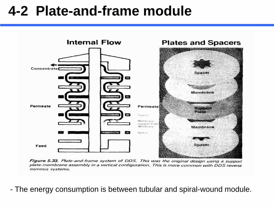
- The energy consumption is between tubular and spiral-wound module.
4-2 Plate-and-frame module
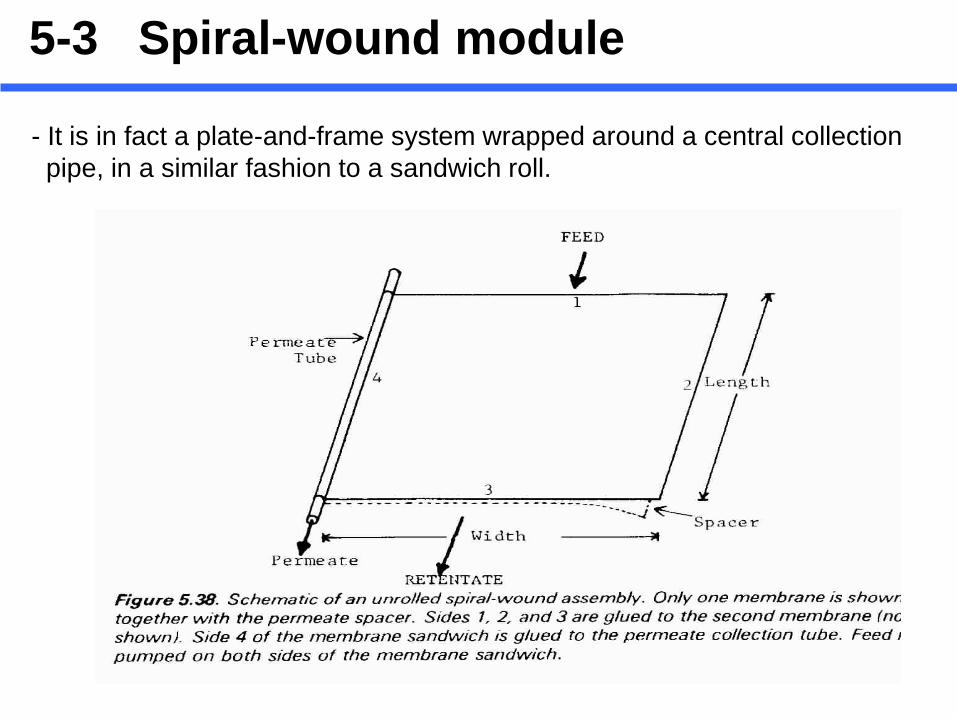
- It is in fact a plate-and-frame system wrapped around a central collection pipe, in a similar fashion to a sandwich roll.
5-3 Spiral-wound module

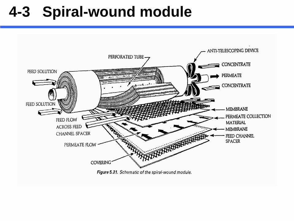
4-3 Spiral-wound module
4-3 Spiral-wound module

- Packing density : 300-1,000 m2/m3 > plate-and-frame module
4-3 Spiral-wound module
- Particles hang-up in the mesh network, resulting in cleaning problem. This makes it difficult to process feeds containing suspended particles. Spiral-wound modules work best on relatively clean feed streams with a minimum of suspended matter.

-Larger channel height : Decrease packing density Minimize pressure drops Reduce feed channel plugging
- “one-tenth rule must be modified for the spiral-wound module due to the pre- sence of the spacer which reduces the free volume in the channel”
i) 30 mil (=760 μm) spacer → prefiltration down to 5-25 μm
ii) 45 mil (=1,140 μm) spacer → prefiltration down to 25-50 μm
4-3 Spiral-wound module
One-tenth rule: the largest particles that can be processed in a membrane module should be less than one-tenth the channel height , taking into account the flocculation.

- A number of spiral-wound modules are assembled in one pressure vessel and are connected in series via the central permeate tube.
4-3 Spiral-wound module
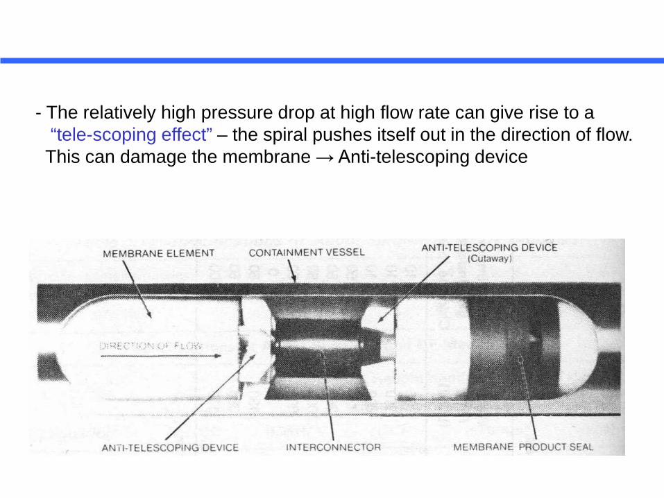
- The relatively high pressure drop at high flow rate can give rise to a “tele-scoping effect” – the spiral pushes itself out in the direction of flow. This can damage the membrane → Anti-telescoping device

The state of turbulence in the spiral wound module is not too clear.
The superficial velocity (v) )(sec baareationalcross
rateflowvolumetric×−
=
a : width of the flat sheet-glued portion b : channel height
v = 10-60 cm/sec Re = 100-1,300
(Laminar Region)
But additional turbulence contributed by the spacers, which can be substantial, should also be taken into account.
4-3 Spiral-wound module
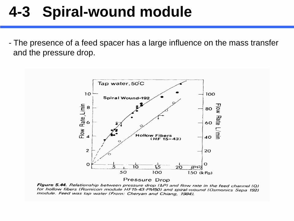
- The presence of a feed spacer has a large influence on the mass transfer and the pressure drop.
4-3 Spiral-wound module

- The state of turbulence :
ΔP = f(Q)n Q : flow rate (L/min) ΔP : pressure drop (kPa)
If n = 1, laminar flow If n = 1.5-1.9, turbulent flow
In Fig. 5.44., pressure drop at v = 25 cm/sec (12 L/min) is 15-20 psig
- EQ = ΔP x Q
The combination of low flow rates, high pressure drops, and relatively high turbulence makes the spiral module one of the more economical modules in terms of power consumption
4-3 Spiral-wound module

4. Tubular Module
●The difference between tubular, capillary and hollow fiber module arises mainly from the dimensions of the tubes employed.
4 - 4 Tubular module

● In contrast to capillary and hollow fiber, tubular membranes are not self-supporting. The membranes are placed inside a ceramic, a porous stainless steel and plastic tube with the diameter of the tube being more than 10mm.
4 - 4 Tubular module

- The feed solution always flows through the center of the tubes while the permeate flows through the porous supporting tube into the module housing.
- Large channel diameter → handling fairly large particles.
“Rule of thumb” ; the largest particles that can be processed in a membrane module should be less than one-tenth the channel height ,taking into account the flocculation.
- Re > 10,000 → operate under turbulent conditions
Recommended Velocities for UF : 2-6 m/sec
- The straight-forward open tube and high Re number make it easy to clean by stand and “C.I.P.” (Clean In Place) technique.
- Inserting scouring balls or roads to help clean membrane
4 - 4 Tubular module
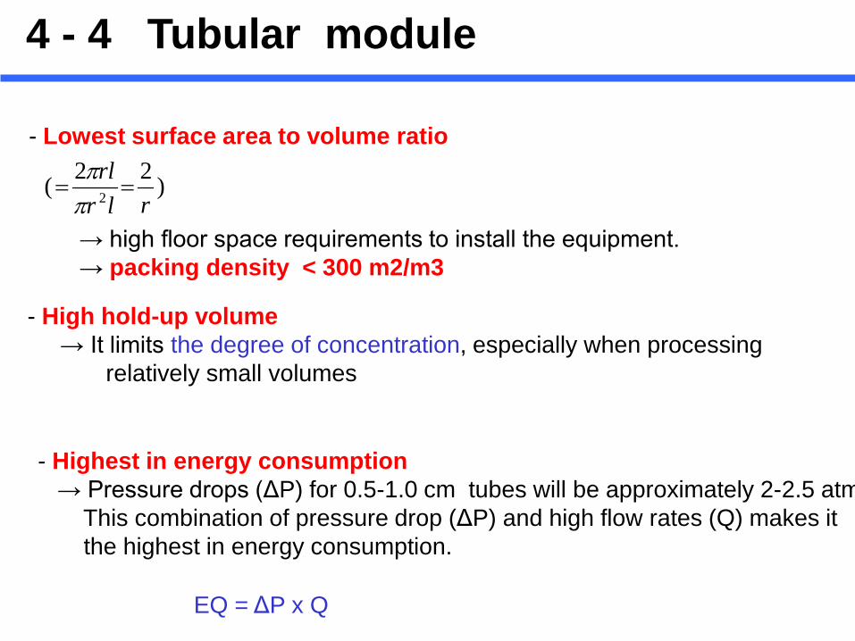
- Lowest surface area to volume ratio
)22( 2 rlrrl==
ππ
→ high floor space requirements to install the equipment. → packing density < 300 m2/m3
- High hold-up volume → It limits the degree of concentration, especially when processing relatively small volumes
- Highest in energy consumption → Pressure drops (ΔP) for 0.5-1.0 cm tubes will be approximately 2-2.5 atm This combination of pressure drop (ΔP) and high flow rates (Q) makes it the highest in energy consumption.
EQ = ΔP x Q
4 - 4 Tubular module

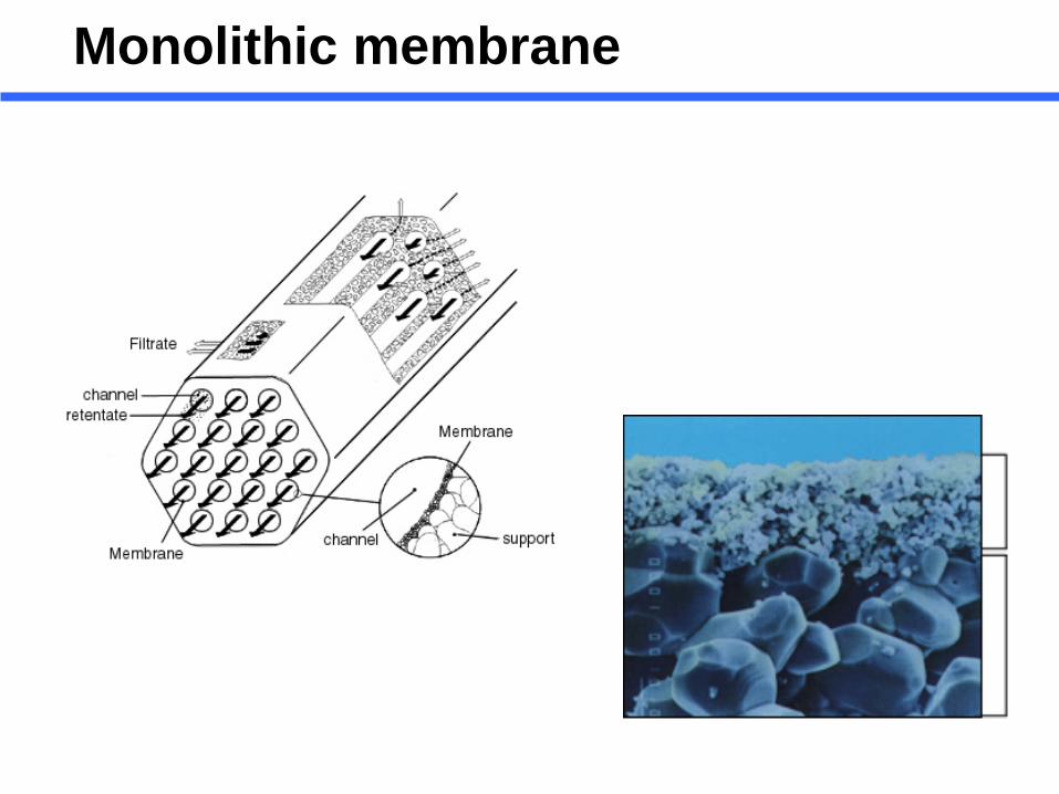
- Monolithic membrane :
i) special type of ceramic membrane. ii) A number of tubes have been introduced in a porous ceramic “block”. iii) The inner surfaces of these tubes are then covered by a skin layer, for instance by a sol-gel process.
4 - 4 Tubular module

Monolithic membrane
Monolithic membrane
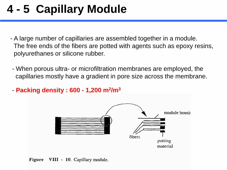
- A large number of capillaries are assembled together in a module. The free ends of the fibers are potted with agents such as epoxy resins, polyurethanes or silicone rubber.
4 - 5 Capillary Module
- When porous ultra- or microfiltration membranes are employed, the capillaries mostly have a gradient in pore size across the membrane.
- Packing density : 600 - 1,200 m2/m3
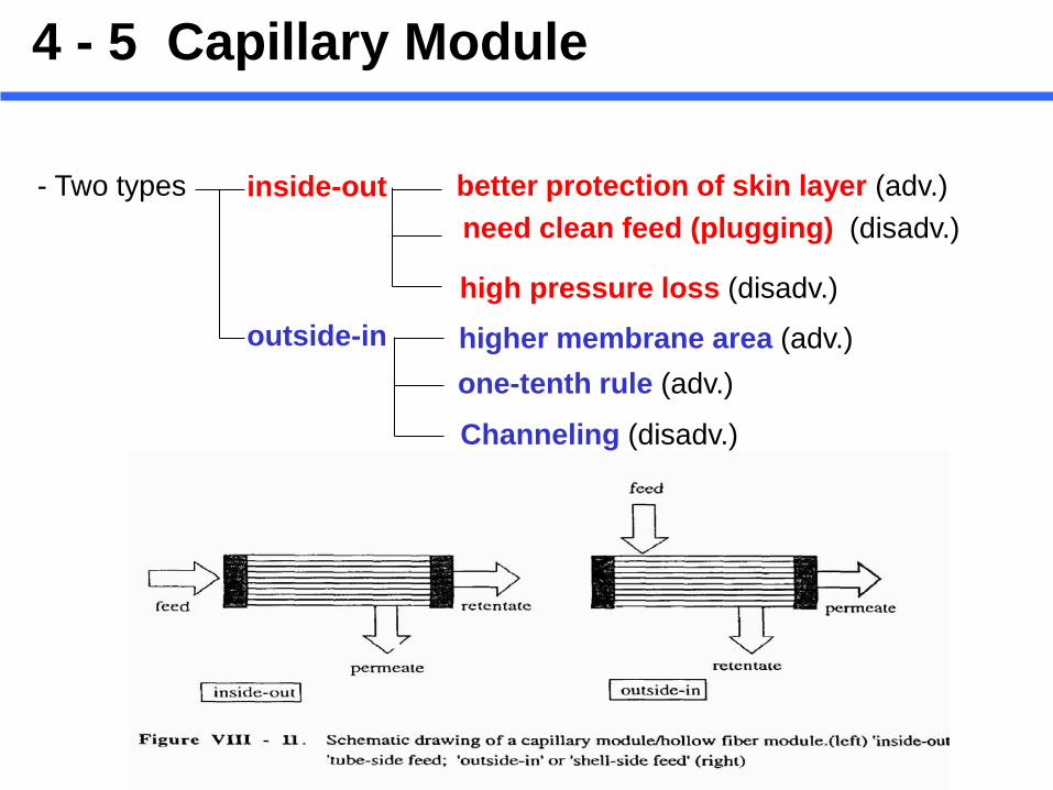
- Two types inside-out
outside-in
better protection of skin layer (adv.) need clean feed (plugging) (disadv.)
high pressure loss (disadv.)
higher membrane area (adv.) one-tenth rule (adv.)
Channeling (disadv.)
4 - 5 Capillary Module
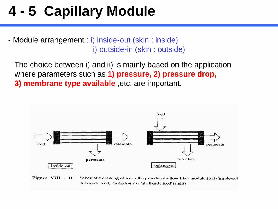
- Module arrangement : i) inside-out (skin : inside) ii) outside-in (skin : outside)
The choice between i) and ii) is mainly based on the application where parameters such as 1) pressure, 2) pressure drop, 3) membrane type available ,etc. are important.
4 - 5 Capillary Module

4 - 6 Hollow fiber Module

4 - 6 Hollow fiber Module
- Fibers : self-supporting structures Thickness : ~ 200 μm Outer diameters = 0.5 ~ 0.7 mm Inner (lumen) diameter = 0.3 ~ 0.5 mm Bundles : 50-3,000 individual fibers Sealing : epoxy resin Cartridge shell : clearsee-through polysulfone or translucent PVC - The Highest Packing Density : up to 30,000 m2/m3 - Hold up volume is low.
- Pressure drop (ΔP) = 5-20 psig usually the inlet pressure (Pi) cannot exceed 25 psig.

- Recommended operating velocity (inside-out) : 0.5-2.5 m/sec (Re = 500-3,000) → operate always in the laminar flow region. - Shear rates are very high ( = 4,000-14,000 sec-1).
- Two types like capillary module: Feed from outside-in (shell-side) or inside-out (lumen side) - Membrane replacement costs are high : Even if one single fiber out of 50-3,000 in bundle bursts, the entire cartridge has to be replaced. However, partial blocking of damaged fibers are possible. - The small tube diameter (<500 μm) make the fibers somewhat susceptible to plugging at the cartridge inlet. → need prefiltration
4 - 6 Hollow fiber Module
w•
γ
4 - 6 Hollow fiber Module *Hollow fiber : very susceptible to fouling and difficult to clean. : the cost of sophisticated pretreatment procedures should be taken into account (capital + operating costs). * Tubular : well suited for applications with a high fouling tendency because of its good process control and ease of membrane cleaning (for example, scouring ball) -A big advantage : i) back-flushing capability ii) Lumen-flushing

Alternative direction of feed flow & Backflushing

Lumen flushing
Permeate in the shell side goes back to the lumen where permeate flow is shut off for brief periods during operation or recycle Partially cleaning the fibers during process
Permeate Recycle
Lumen flushing
Principle of lumin flushing

4-7. Comparison of module configurations
- The choice of module is based on :
i) Economic consideration
ii) Type of application

Membrane Modules
Classification II :
- Contained Module (Pressure Vessel)
- Submerged Module (or Immersed Module )
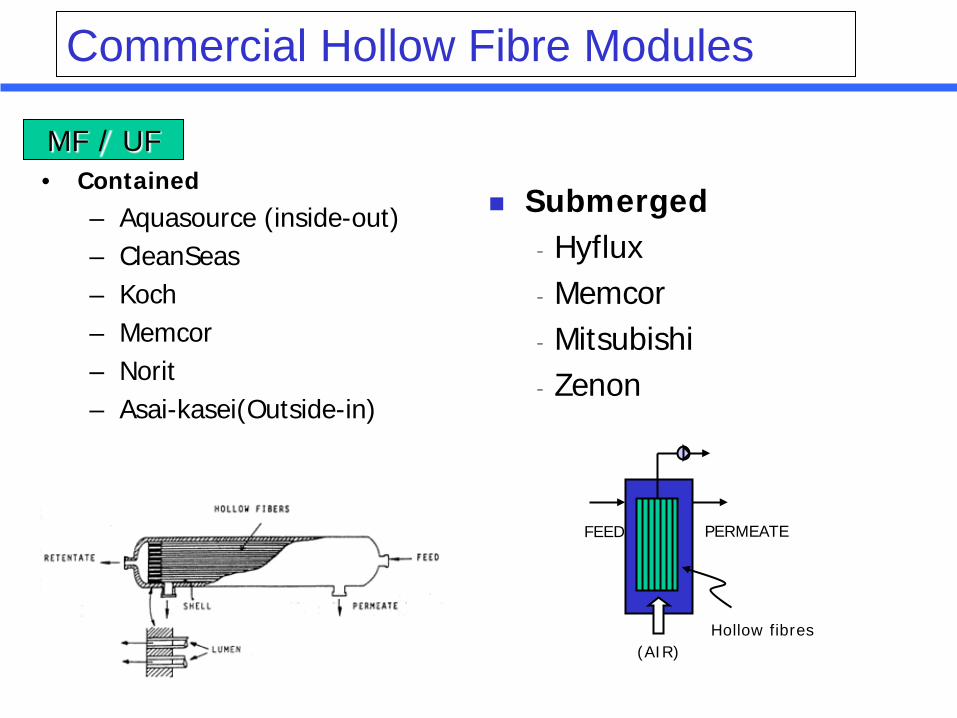
Commercial Hollow Fibre Modules
• Contained
– Aquasource (inside-out) – CleanSeas – Koch – Memcor – Norit – Asai-kasei(Outside-in)
FEED PERMEATE
(AIR) Hollow fibres
Submerged - Hyflux - Memcor - Mitsubishi - Zenon
MF / UF

• Membranes ( tubes, fibres, flat sheets) mounted in a pressure vessel.
• Transmembrane pressure provided by pumped feed.
• Design determines fluid management.
Contained Module

http://www.aquasource-membrane.com
Hollow-fiber type
Contained Module

FW50 FN20
DAICEN MEMBRANE SYSTEMS (Cellulose)
Contained Module

Double skin hollow fiber UF
MF: USV-6203
Asai-kasei
Contained Module : Hollow Fiber

Membrane module
KURARAY
SF filter
Contained Module : Hollow Fiber

Ceramic membrane (monolith: CF2KMO1)
Membrane module (CF2KMO1-005N)
NGK
Drinking water treatment plant (425 m3/day)
Contained Module : Ceramic Membrane

• Hollow fibres (vertical or horizontal) of flat sheets (vertical) immersed in atmospheric
tank • Permeate removed by suction pump or gravity • Cake controlled by bubbling and/or backwash • Applications: Water treatment and MBRs
• ADVANTAGES: – Avoids pressure vessel – Reduces cost – Ease of membrane replacement – Simple scale up – Lower energy consumption
• DISADVANTAGES:
– Driving force < 1 atm – Poor fluid management
FEED
(AIR)
Hollow fibres or flat sheet
PERMEATE
Submerged Module
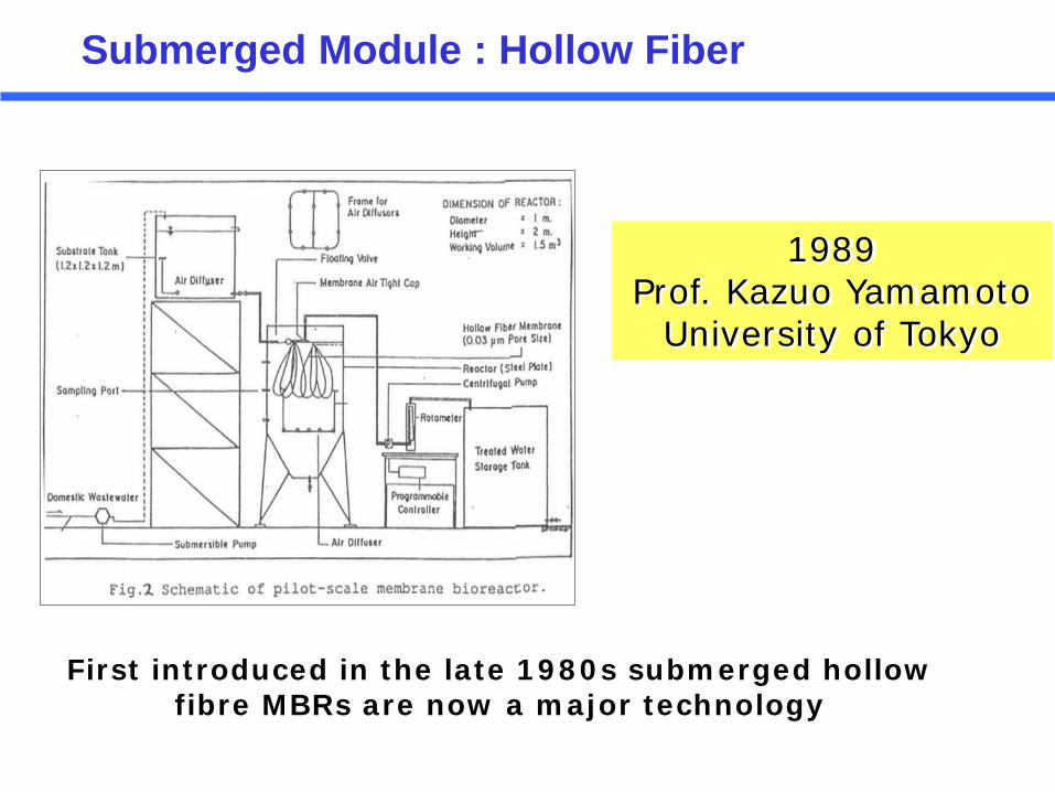
1989 Prof. Kazuo Yamamoto
University of Tokyo
First introduced in the late 1980s submerged hollow fibre MBRs are now a major technology
Submerged Module : Hollow Fiber

ZeeWeed® 500 Series
ZeeWeed® 1000 Series
ZENON
Submerged Module : Hollow Fiber
Dr. Pierre Cote
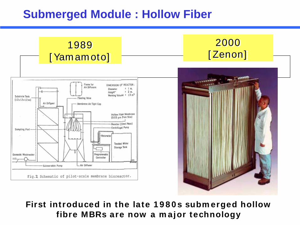
1989 [Yamamoto]
2000 [Zenon]
First introduced in the late 1980s submerged hollow fibre MBRs are now a major technology
Submerged Module : Hollow Fiber
IWA Membrane Conference 26 August 2013
Pierre Côté, Ph.D.
COTE Membrane Separation Ltd
7th IWA Specilaized Membrane Technology Conference and Exhibition for Water and Wastewater Treatment and Reuse
Keynote Speech

“Our species is the only creative species, and it has only one creative instrument, the individual mind and spirit of man. Nothing was ever created by two men. There are no good collaborations, whether in music, in art, in poetry, in mathematics, in philosophy. Once the miracle of creation has taken place, the group can build and extend it, but the group never invents anything. The preciousness lies in the lonely mind of a man.” John Steinbeck, East of Eden, 1952

element MRM2019
MITSUBISHI RAYON Polyethylene (hollow fiber)
(for drinking water)
Filtration and back washing
Submerged Module : Hollow Fiber

LFM7823 element
ジ ジ ジ ジ ジ
原水
原水
処理水
処理水
処理水
中空糸膜
Feed Water
Treated Water
Hollow Fiber Membrane
処理水
MITSUBISHI RAYON Polyethylene (hollow fiber)
(for drinking water)
Submerged type
(suction filter)

Example: Large Scale Submerged Hollow Fibre Water Treatment Plant
The figure shows a 120 ML/d design with 6×20 ML/d chambers (similar concept to conventional sand filters). Filtered solids are removed from membrane by liquid backwash and external air-scour. Chemical cleaning is occasionally required.
CMF-S plant, 6 × 144-4S10T (nominal 120 ML/day)

ユミクリン加圧型モジュール(YC型)
ユミクリン浸漬型モジュール(T型)
YUASA
Submerged Module: Flat Sheet


![Journal of Membrane Science & Research Selective Mass ...€¦ · of zeolite membranes for development of membrane modules, which was a big problem in the past [5], is now overcome](https://img.dokumen.tips/doc/110x75/6005fa765df75f27431eb850/journal-of-membrane-science-research-selective-mass-of-zeolite-membranes.jpg)