Embed Size (px)
Citation preview

Chapter 4-
ISSUES TO ADDRESS...
• What types of defects arise in solids?
• Can the number and type of defects be varied and controlled?
• How do defects affect material properties?
1
• Are defects undesirable?
CHAPTER 4:IMPERFECTIONS IN SOLIDS

Chapter 4- 2
• Vacancy atoms• Interstitial atoms• Substitutional atoms
• Dislocations
• Grain Boundaries
Point defects
Line defects
Area defects
TYPES OF IMPERFECTIONS

Chapter 4- 3
• Vacancies:-vacant atomic sites in a structure.
Vacancydistortionof planes
• Self-Interstitials:-"extra" atoms positioned between atomic sites.
self-interstitialdistortion
of planes
POINT DEFECTS

Chapter 4-
Point defects
• Vacancy:• Self-interstitial:• Substitutional
• Fundamental concepts– alloy– solute– solvent– solid solution
• Solute solutions– substitution
• atomic size factor• crystal structure• electronegativity• valences
– interstitial

Chapter 4-
Boltzmann's constant
(1.38 x 10⁻²³ J/atom K)
(8.62 x 10⁻⁵ eV/atom K)
Á ˜ NDN
= exp-QDkT
Ê
Ë Á
ˆ
¯ ˜
No. of defects
No. of potentialdefect sites.
Activation energy
Temperature
Each lattice siteis a potentialvacancy site
4
• Equilibrium concentration varies with temperature!
EQUIL. CONCENTRATION:POINT DEFECTS

Chapter 4- 5
• We can get Q from an experiment.
• Measure this... • Replot it...
1/T
N
NDln 1
-QD/k
slope
MEASURING ACTIVATION ENERGY

Chapter 4- 6
• Find the equil. # of vacancies in 1m of Cu at 1000C.• Given:
3
8.62 x 10⁻⁵ eV/atom-K
0.9eV/atom
1273K
Á ˜ NDN
= exp-QDkT
Ê
Ë Á
ˆ
¯ ˜
For 1m3, N =NAACu
r x x 1m3 = 8.0 x 1028 sites
= 2.7 · 10-4
• Answer:
ESTIMATING VACANCY CONC.

Chapter 4-
T = terraceL = ledgeK = kink

Chapter 4- 7
• Low energy electron microscope view of a (110) surface of NiAl.• Increasing T causes surface island of atoms to grow.• Why? The equil. vacancy conc. increases via atom motion from the crystal to the surface, where they join the island.
Reprinted with permission from Nature (K.F.McCarty, J.A. Nobel, and N.C. Bartelt, "Vacancies inSolids and the Stability of Surface Morphology",Nature, Vol. 412, pp. 622-625 (2001). Image is5.75 mm by 5.75 mm.) Copyright (2001) MacmillanPublishers, Ltd.
OBSERVING EQUIL. VACANCY CONC.

Chapter 4- 8
Two outcomes if impurity (B) added to host (A):• Solid solution of B in A (i.e., random dist. of point defects)
• Solid solution of B in A plus particles of a new phase (usually for a larger amount of B)
OR
Substitutional alloy(e.g., Cu in Ni)
Interstitial alloy(e.g., C in Fe)
Second phase particle--different composition--often different structure.
POINT DEFECTS IN ALLOYS

Chapter 4- 9
• Low energy electron microscope view of a (111) surface of Cu.• Sn islands move along the surface and "alloy" the Cu with Sn atoms, to make "bronze".• The islands continually move into "unalloyed" regions and leave tiny bronze particles in their wake.• Eventually, the islands disappear.
Reprinted with permission from: A.K. Schmid,N.C. Bartelt, and R.Q. Hwang, "Alloying atSurfaces by the Migration of Reactive Two-Dimensional Islands", Science, Vol. 290, No.5496, pp. 1561-64 (2000). Field of view is 1.5mm and the temperature is 290K.
ALLOYING A SURFACE

Chapter 4- 10
Definition: Amount of impurity (B) and host (A) in the system.
• Weight %
Two descriptions:• Atom %
• Conversion between wt % and at% in an A-B alloy:
CB = C'BAB
C'AAA + C'BABx 100
• Basis for conversion:
COMPOSITION

Chapter 4- 11
• are line defects,• cause slip between crystal plane when they move,• produce permanent (plastic) deformation.
Dislocations:
Schematic of a Zinc (HCP):• before deformation • after tensile elongation
slip steps
LINE DEFECTS

Chapter 4- 12
• Dislocations slip planes incrementally...• The dislocation line (the moving red dot)... ...separates slipped material on the left from unslipped material on the right.
Simulation of dislocationmotion from left to rightas a crystal is sheared.
(Courtesy P.M. Anderson)
INCREMENTAL SLIP

Chapter 4- 13
• Dislocation motion requires the successive bumping of a half plane of atoms (from left to right here).• Bonds across the slipping planes are broken and remade in succession.
Atomic view of edgedislocation motion fromleft to right as a crystalis sheared.
(Courtesy P.M. Anderson)
BOND BREAKING AND REMAKING

Chapter 4-
Dislocations-linear defects
• Edge dislocation:• Dislocation line:

Chapter 4-
Edge dislocation

Chapter 4-
Dislocations-linear defects
• Screw dislocation:p Slip plane:p Slip plane contains both Burgers Vectors and dislocation line

Chapter 4-
Dislocations-linear defects
• Mixed dislocation

Chapter 4-
Burgers Circuit &Burgers Vector
p Burgers circuit: any close loopcontain dislocations by an atomto atom path
p Burgers vectors: the vectorrequired to complete the circuitin a perfect crystal; the directionof atom displacement
(a)
(b)
(a) Burgers circuit round an edge dislocation(b) the same circuit in a perfect crystal

Chapter 4- 14
• Structure: close-packed planes & directions are preferred.
• Comparison among crystal structures: FCC: many close-packed planes/directions; HCP: only one plane, 3 directions; BCC: none
Mg (HCP)
Al (FCC)tensile direction
• Results of tensile testing.
view onto twoclose-packedplanes.
DISLOCATIONS & CRYSTAL STRUCTURE
Chapter 4-
Dislocations-linear defects
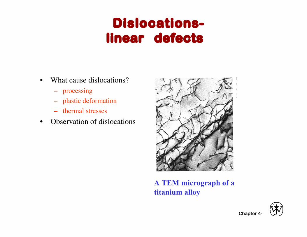
• What cause dislocations?– processing– plastic deformation– thermal stresses
• Observation of dislocations
A TEM micrograph of a titanium alloy

Chapter 4- 15
Grain boundaries: • are boundaries between crystals. • are produced by the solidification process, for example. • have a change in crystal orientation across them. • impede dislocation motion.
grainboundaries
heatflow
Schematic
Adapted from Fig. 4.7, Callister 6e. Adapted from Fig. 4.10, Callister 6e.(Fig. 4.10 is from Metals Handbook, Vol. 9, 9th edition,Metallography and Microstructures, Am. Society forMetals, Metals Park, OH, 1985.)
~ 8cmMetal Ingot
AREA DEFECTS: GRAIN BOUNDARIES

Chapter 4- 16
• Useful up to 2000X magnification.• Polishing removes surface features (e.g., scratches)• Etching changes reflectance, depending on crystal orientation.
close-packed planes
micrograph ofBrass (Cu and Zn)
Adapted from Fig. 4.11(b) and (c),Callister 6e. (Fig. 4.11(c) is courtesyof J.E. Burke, General Electric Co.
0.75mm
OPTICAL MICROSCOPY (1)

Chapter 4- 17
Grain boundaries...• are imperfections,• are more susceptible to etching,• may be revealed as dark lines,• change direction in a polycrystal.
Adapted from Fig. 4.12(a)and (b), Callister 6e.(Fig. 4.12(b) is courtesyof L.C. Smith and C.Brady, the NationalBureau of Standards,Washington, DC [now theNational Institute ofStandards andTechnology,Gaithersburg, MD].)
OPTICAL MICROSCOPY (2)

Chapter 4-
Interfacial defects (twodimension)
p External surfacesp Grain boundaries

Chapter 4-
Bulk Defects (threedimension)
p Voidp Cracksp Inclusions
TEM image of voids

Chapter 4- 18
• Point, Line, and Area defects arise in solids.
• The number and type of defects can be varied and controlled (e.g., T controls vacancy conc.)
• Defects affect material properties (e.g., grain boundaries control crystal slip).
• Defects may be desirable or undesirable (e.g., dislocations may be good or bad, depending on whether plastic deformation is desirable or not.)
SUMMARY

Chapter 4-
Reading:
Core Problems:
Self-help Problems:
0
ANNOUNCEMENTS


![Imperfections in Solids [Autosaved]](https://img.dokumen.tips/doc/110x75/56d6bcc11a28ab30168b54f1/imperfections-in-solids-autosaved.jpg)