Embed Size (px)
Citation preview

Chapter 4 Governors
In a power plant, turbine or engine, is connected to generator. Generator runs at constant rated speed
also at particular load. If generator is running at full load and suddening it trips off (i.e. load becomes
zero), there is a possibility speed may go high enough to break the shaft because the turbine or the
engine is still generating the power. There has to be some device, which can control the input (either
steam or fuel) to the turbine or engine as the load decreases or increases. By governors we can control
the speed of generators. Flywheel is used to smoothen out speed over a cycle of rotation. i.e it is a
energy storting and releasing device over a cycle. By gyroscope we can control the guidance.
The function of a governor is to maintain speed under certain limits under varying load condition
(from full load to no load). Flywheel cannot keep speed limits constants for varying load conditions.
Figure 1 shows functions of the flywheel and the governor.
Time
Load variationwith flywheelwithout Governor
mean speed
Governor control(withflywheel)
Load
speed
withgovernorwithoutflywheel
cyclic variation controlledby flywheel
one cycle
Figure 1 Comparison of flywheel and governor
Types of governors: (i) Centrifugal type: It depends upon the ω
(ii) Inertia type: It depends upon the αω=
dt
d
The centrifugal type is subdivided into
(i) Gravity loaded – the Watt, Porter and Proell governors
(ii) Spring loaded – the Hartnell, Wilson-Hartnell, Hurtung and Pickering governors.

67
Watt GovernorO2
2
3
4lower ball arm
upper ball arm
B
fly ball
path of ball B
BV
sleevemoment
sleeve spindle(or shaft)(driven by outputshaft of the primeover)This movement will
actuate the throttle valve in steam valve (highestposition of sleeve-closed & lowest position ofsleeve-open throttle)
Fig.1
h
C
T2
BFC
MbgT3=0
r
O2
Fig.2
T 3=0
Fig.3
T3 =0
Free body diagram of ball B, neglecting masses of upper arm, lower and sleeve, we can get the force
balance. let
→CF Centrifugal force
Figure 2 Watt Governor
Figure 3 Free body diagram of ball B
Figure 4 spindle or shaft

68
→2T Tension in arm 2
→bm mass of each ball
→h height of governor
→r radius of flyball rotation
Along x direction
∑ =→+
0xF
0coscos 33 =− φφ TT
Along y direction
∑ =+↑ 0yF
0sinsin 33 =+ φφ TT
0sin2 3 =φT
3 0 sin ce sin 0T φ= ≠
From Fig 2, on taking moment about 2O , we get
rgmhF bC .=⋅ or grmrhm bb =2ω
or 2/h g ω= (4.1)
where 2 / 60Nω π= N in rpm, ω in rad/sec, 2 in and in / sech m g m
From Fig 2, we have
From hrBCO /tan,2 =∆ θ or coth r θ= (4.2)
Force balance is given as
∑ =↑+ 0yF ,
2cos
bT m gθ = (4.3)
From equation (4.1) we can note that the height of the governor, h, is independent of mass of ball and
also length of supporting arms.

69
hcm
speed(rpm)
h1
h2
Figure 5 Variation of governor height with speed
Watt governor is not sensitive to the high speed of operation. As the % change in sleeve height is very
small at high speed.
Or 2 1h h∆ << ∆ for same ω∆
where →∆ 2h at high speed and →∆ 1h at low speed
It should be more sensitive at high speeds. So Watt governors are suitable for low speed operations.
Porter Governor:
It is similar to Watt governor except the sleeve weight is appreciable. This modification leads to larger
centrifugal forces i.e. higher speeds are needed to bring the fly balls to the same radius.
O
B2
3 4
C
h
r
Figure 6 A Porter governor
β

70
T3 T3
MCg
Figure 7 Free body diagram of sleeve.
Where
cm →mass of sleeve
From free body diagram of sleeve, we have
∑ =↑+ 0yF
32 cos cT m gβ =
or 3 cos 0.5 cT m gβ = (4.4)
T2
T3mbg
F=mb2r
Figure 8 (II) Free body diagram of ball B
∑ =↑+ 0yF
gmTT b+= βα coscos 32 (4.5)
Substituting Equation (4.4) in Equation (4.5), we get
2 cos 0.5 c bT m g m gα = + (4.6)
β
β

71
T3
T3
Figure 9 (III) Free body diagram of link 3
∑ =→+
0xF
FTT =+ βα sinsin 32 (4.7)
Substituting Eq.(4.4) in Eq. (4.7), we get
2
sinsin 0.5
coscT m g F
βα
β+ =
or 2 sin 0.5 tancT F m gα β= − (4.8)
Dividing Eq. (4.8) by Eq.(4.6), we get (to eliminate 2T )
0.5 tantan
0.5
c
c b
F m g
m g m g
βα
−=
+
or tan
0.5 0.5tan tan
c b c
Fm g m g m g
βα α
+ = − (4.9)
Let q=αβ
tan
tan, using hr /tan =α and rmF b
2ω= , we get from equation (4.9)
2
0.5 0.5/
b
c b C
m rm g m g m gq
r h
ω+ = − or ( ) 20.5 1C b bm g q m g m hω+ + =
or ( )
2
0.5 1c b
b
m q m gh
m ω
+ + = (4.10)
which can be written as
( )
20.5 1
b c
b
m m q g
m hω
+ + = (4.11)

72
where =ω 60/2 Nπ=
N in rpm and ω in rad/sec.
WattPorter
h
Figure 10
If in figure O & C are in the same vertical line i.e. βα = then 1=q (i.e. of equal upper and lower
arm)
2 b c
b
m m g
m hω
+= (4.12)
For sleeve weight 0cm = , from Eq. (4.12) we have 2 /g hω = which is same as (1) of Watt governor.
For same speed the height of porter governor may be made as much greater than the height of Watt
governor by choosing a suitable value for the ratio /c bm m .If Sf is the total frictional forces on the
sleeve then equation (4.11) can be written as:
( )2
1/ 2 /.
b c S
b
m m f g g
m hω
+ ± = (4.13)
where →+ when sleeve in going up and →− when the sleeve is going down.
Alternative method: By taking moment about instantaneous center of link 3, (i.e. I), we can eliminate
2T force. In the previous method we eliminated 2T in equation (4.9).
O
2 B
F
IMC
r
3
Figure 11 Free body diagram of one half of the governor (external forces & inertia forces acting)
on).

73
Taking moment about instantaneous center I of the link 3, we get:
( ) ( )0.5b cFBM m g IM m g IC= +
or ( ) ( )0.5b c
IM ICF m g m g
BM BM= +
( ) ( ) ( )BM
IMCMgmgm Cb
++= 2/1tanα
( ) ( )( )αβα tantan2/1tan ++= gmgmF Cb (4.14)
Now we have
h
r=αtan and rmF b
2ω=
We get from eq. (4.14)
( )[ ]( )hrqgmgmrm Cbb /12/12 ++=ω
( )
2
1/ 2 1.
b C
b
m m q gh
m ω
+ + = (4.15)
where ,tan
tan
αβ
=q
( )2
1/ 2 1.
b C
b
m m q g
m hω
+ + = (4.16)
Equilibrium speed for particular h from Equation (4.15) and (4.16) are same as Equation. (4.10) and
(4.11), respectively.
Proell Governor
Proell governor is similar to Porter governor except the balls are attached to the extension to the lower
arm. Only advantage is that it reduces the speed required for a given lift to the sleeve as compared to
governor.

74
O
upper arm
Ball(attachedto lowerarmextension
Lower arm(Bell crank lever)
sleeve
Figure 12 Proell governor
h
Or
B
A
ID
C
E
mbg
For purpose of analysisextended arm isassumed to be vertical
External forces inertia force acting onone half of governor
QmCg/2
F
F=mb r2
Taking moment about I of all external forces in right half of the governor, we get
0.5b CFBD m gID m gIC= + , dividing both sides by AD and since , AD
ID=αtan &
AD
CD=βtan ,
we can write
( )tan 0.5 tan tanb c
BDF m g m gAD
α α β= + +
or
( )0.5 1 tanb c
ADF m m q g
BDα= + + (4.17)
ββ
Figure 13 External forces inertia force acting on one half of governor

75
where αβ tan/tan=q ; rmF b2ω= and
h
r
h
AE
EO
AE≈==αtan (for all practical purpose).
From equation (4.17), we get
( )[ ] hrgqmmBD
ADrm Cbb /.12/12 ++=ω
or ( )2 1/ 2 1b C
b
AD gm m q
hmBDω = + + (4.18)
when βα = , 1=q , then
2 b c
b
m mAD g
m hBDω
+=
(4.19)
Since 1<BD
Ad, the effect of placing the fly-balls at B instead of A is found to reduce the equilibrium
speed for a given ,b cm m and h. So far same equilibrium speed for given h and cm the Proell governor
requires fly ball masses smaller in side as compared to Porter governor. With sleeve friction equation.
(4.18), can be written as:
{ }( )2
0.5 / 1b C S
b
m m f g q gAD
hmBDω
+ ± + = (4.20)
where positive is for increasing speed and negative is for decreasing speed.
Governors Performance Parameters:
(i) Sensitiveness:- The main objective of a governor is to maintain a constant mean speed as closely
as possible, whatever may be the load on the engine. It is desirable that movement of sleeve should be
as large as possible corresponding to fractional change of equilibrium speed as small as possible.
Smaller the fractional change of speed for a given displacement of the sleeve or the larger the
displacement of sleeve for a given fractional change of speed, the more sensitive is the governor said
to be. The sleeve displacement actuates the throttle valve of engine i.e. it regulates the energy supplied
to the engine. The sensitiveness (S) is more accurately defined as (as we more bothered about the
variation of speed from mean)

76
( )( )minmax
minmaxminmax 21
NN
NN
N
NN
S mean +
−=
−= where insensitiveness ( )1/ S
(ii) Stability: A governor is said to be stable when for each speed within the working range there is
only one radius of rotation of the fly-ball at which governor is in equilibrium. If a governor is in
equilibrium in all possible configurations at the equilibrium same speed, such a governor is said to be
Isochronous. In most of case isochronous governors are not stable and so is useless. (Since
sensitiveness is infinite. i.e. for a small speed variation, the governor from its one extreme position
will shift to the other extreme).
Isochronous condition of governor: A governor is said to be isochronous if equilibrium speed is same
for all possible configuration of governor within the working range. i.e. for different radius 1, r r and
2r equilibrium speeds are min max eqω ω ω= = i.e. speed range becomes zero.
( )( )
02/
1
minmax
minmax =+
−=
ωωωω
S which gives S = ∞
Moreover, we have centrifugal forces as
rmF b2ω= ; 11
2min1 CrmF b == ω ; 2
2 max 2 2bF m r Cω= =
where C is the controlling force. Since we have min max eqω ω ω= = for isochronous, hence we get
1 2 1 2/ /r r C C= is the condition of isochronous.
(iii) Hunting: A governor is said to be hunt if the speed of the engine fluctuates continuously above
and below the mean speed. It occurs when governor is too sensitive i.e. for a small variation of speed
causes large change in the fuel supply (i.e. sleeve). When the load increases, it causes the reduction in
the speed of the governor and actuates the fuel supply valve to wide open. Due to the excess fuel
supply the speed increases, governor actuates the fuel supply valve to fully closed and the engine
speed begins to fall. This cycle is repeated. This sort of governor, which admits maximum or
minimum amount of fuel will cause wide fluctuation of speed and thus hunts.
Spring- controlled fly-ball governor:
Centrifugal force is controlled by the spring force. It can be operated at very high speed & with a
good proportioning of links. They can be very powerful and very close regulation. They can be
designed to be in smaller sizes. They may be rotated about a horizontal or inclined axis. The spring

77
may be compressed initially and this initial compression can be adjusted to give any required
equilibrium speed for a given ball radius.
(i) Hartnell type Governor:
r
Flyball
K
Compressedspring axially movable
sleeve
spindleFrame attachedto spindle
rightanglebellcrank
Figure 14 A Hartnell governor
r
mbg
F
ba
1/2(S+mCg)
Figure 15 Freebody diagram of the arm
In freebody diagram of the arm, on taking moment about the point A:
[ ]cos sin 0.5 cosb cFb m g b S m g aθ θ θ+ = + (4.21)
where S is the spring force on sleeve, ,a b are bell crank arm length and θ is the inclination of bell
crank arms. Dividing by cosθ , we get:
[ ]tan 0.5b cFb m gb S m g aθ+ = + (4.22)
If the spindle is horizontal then the effect of gravity of bm and cm will be zero on sleeve.
0.5Fb S a= i.e. 2 0.5 /bm r S a bω = (4.23)
For two speeds 1ω and 2ω let 1r and 2r be the radius of fly-ball for equilibrium is to reach i.e.
b
aSrmb
1211 2/1=ω (4.24)
b
aSrmb
2222 2/1=ω (4.25)
A

78
Eqs.(4.24) and (4.25) can be combined as
or 2
2 2 2
2
1 1 1
r S
r S
ωω
= (4.26)
For isochronism 12 ωω = i.e 1
2
1
2
s
s
r
r= (4.27)
Hence, the spring force must increase in proportion to the increasing radius of the balls
r
r1 C1
F1B1
x1
mbg
h1
y1
A11
1
(mcg+S1)
2Fig. 1Minimum position
rC2
r2 B2
F2
mbg
b
A2
X2
y2
ah2
2
2
(mCg+S2 )
2
Fig. 2
Maximum Position
Let h be the compression of the spring when the radius of rotation changes from 1r to 2r
i.e. 21 hhh +=
From Fig.17 from two similar '∆ s b
rr
a
h −= 22 (4.28)
From Fig. 16 from the similar '∆ s b
rr
a
h 11 −= (4.29)
Therefore b
rr
a
hh
a
h 1221 −=
+= (4.30)
i.e. ( )12 rrb
ah −= (4.31)
Taking moments about A, in Fig. 17 and Fig. 15 , we get
2
2 2 2 22
cb
m g Sy F x m gC
+= + or [ ]2 2 2 2
2
2c bm g S F x m gC
y+ = + (4.32)
and
Figure 16 Minimum position
Figure 17 Minimum position

79
1
1 1 1 12
cb
m g Sy F x m gC
+= − or [ ]1 1 1 1
1
2c bm g S F x m gC
y+ = + (4.33)
Therefore 12 SS − [ ]222
2
2gcmxF
yb+= - [ ]111
1
2gcmxF
yb+ (4.34)
But we also have hkSS =− 12 (4.35)
where h is the total compression of spring and k is the spring constant (linear). Combining Eqs.(4.31)
and (4.32), we get
2 1 2 1
2 1
S S S S bk
h r r a
− −= =
− (4.36)
For small θ , the obliquity of arm can be neglected as i.e. bxx == 21 and ayy == 21 . Also
neglecting the moments due to gravity force of the balls, then from equation (4.34) we get
( )a
bFFSS
21212 −=− (4.37)
Combining eqs. (4.36) & (4.37), we get
( )( )
( )22 1
2 1
2/b
F Fk b a
r r
−=
− (4.38)

80
(ii) Spring controlled Governor with auxiliary spring (Wilson-Hartnell governor)
Primary spring
Kb Right anglebell crank
Rotatingframe
Auxilaryspring
Lever KaB
S
yx
A
a
b
C
Sleeve
Figure 18 Wilson-Hartnell governor
P F
b
Aa
1/2(mCg+S.y/x)
Figure 19 Freebody diagram of the arm
Taking moment about the fulcrum of the bell crank lever and neglecting the mass of ball, we get
( ) ( )0.5 /cF P b m g Sy x a− = + (4.39)
where P is the primary spring force and S is the auxiliary spring force. At minimum equilibrium
speed, we have
( ) ( )1 1 10.5 /cF P b m g S y x a− = + (4.40)
Similarly for the maximum equilibrium speed
( ) ( )2 2 20.5 /cF P b m g S y x a− = + (4.41)

81
From Eqs. (4.40) and (4.41), we get
( ) ( ) ( )2 1 2 1 2 12
y aF F P P b S S
x − − − = − (4.42)
From the minimum equilibrium position ( )1r to maximum equilibrium position ( )2r , we have
The total extension of primary spring = ( )122 rr − (4.43)
Correspondingly the sleeve movement ( )12/ rrba −= (4.44)
The extension of the auxiliary spring ( )2 1( / ) ( / )a b r r y x= − (4.45)
Noting Equation. (4.43), we have
( ) ( )1212 2 rrkPP b −=− (4.46)
Noting Equation. (4.45), we have
( ) ( )2 1 2 1 /( )aS S k r r ay bx− = − (4.47)
Hence, we can write
( ) ( ) ( )2 2
2 1 2 1 2 12 0.5 ( ) /( )b aF F k r r k ay r r bx− = − + − (4.48)
or
( ) ( )22 1
2
2 1
0.52
( )
a
b
F F k ayk
r r bx
−= +
− (4.49)
Either ak or bk may be fixed arbitrarily and the value of the other stiffness can be calculated from
Equation (4.49).
Without auxiliary spring the above equation takes the following form
( )( )2 1
2 12b
F Fk
r r
−=
− (4.50)
(iii) Spring controlled governor with bell crank attached to the sleeve:
A cap is fixed with the spindle. By friction or some arrangement the spring & the sleeve is also
rotating. Under the action of the centrifugal force the spring is getting compressed. Sleeve is having
axial movement also. Bell cranks are attached to the sleeve. The sleeve weight and the spring force
are coming to the bell crank through the pivot at B. Pivot B moves axially and point C moves radially
inward or outwards. So instantaneous center of bell crank will be at I.

82
bellcrank
B CapC
AF
Sleeve(moving)
Spring undercompression
mbg
r
I
mCg+S
2
Figure 20 Spring loaded governor
Cap
Spindle
Figure 21 Spindle of the governor
C
IBD
A
mbg
F
1/2(mSg+S)
Figure 22 Freebody diagram of bell crack

83
From freebody diagram, we have
∑ =↑+ 0IM
( )0.5b cF AD m gDI m g S BI= + + (4.51)
or
( )2 /c bm g S F AD m gDI BI+ = − (4.52)
(iv) Hartung Governor
Spring ball
Spring
Sleeve
Frame
Bell cranklever
Hartung Governor:
Figure 23 Hartung Governor
r
F
b
O a
S
m Cg
2
Figure 24 Freebody diagram of the bell crack
level
Fly-balls are directly controlled by direct springs. Vertical arm of bell crank is fitted with spring balls,
which compresses against the springs. Horizontal arm is attached to the sleeve. Taking moment about
fulcrum O (neglecting the effect of obliquity of the arm), we get
/ 2cFb Sb m ga= + (4.53)
Governor effort and Power:
If sudden variation of speed takes place then the sleeve tends to move to its new equilibrium position
and a force is exerted to the sleeve mechanism. This force diminishes to zero as the sleeve moves to
the equilibrium position corresponding to the new speed. The mean force exerted during a given
change of speed is termed as the effort. For convenience to compare different governors it is defined
as the effort or force that can be exerted by a 1% change of speed. The power of a governor is defined
as the work done at the sleeve for given percentage change of speed. Power is the product of effort
84
and the displacement of the sleeve. The power required depends upon the controlling mechanism
which governor operates. For high power required to operate the fuel supply valves, pneumatic or
hydraulic pressure is used to operate such valves.
Porter Governor:
h
mbg
FC= m g
C
N,
F
h1
F1
m gb
xF = m g
CC1
N1 1
F
h
m gb
1
FC2
Total Force requiredat sleeve to retainthe sleeve at sameinitial positionwhen increases to
1
Wt.
FC=FC1= mCg
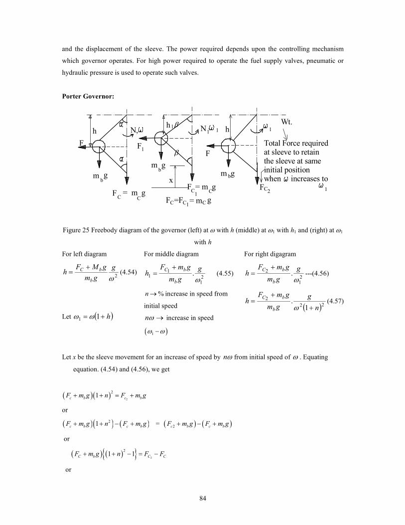
Figure 25 Freebody diagram of the governor (left) at ω with h (middle) at ω1 with h1 and (right) at ω1
with h
For left diagram
2ωg
gm
gMFh
b
bC += (4.54)
Let ( )h+= 11 ωω
For middle diagram
21
11 .
ωg
gm
gmFh
b
bC += (4.55)
%n→ increase in speed from
initial speed
→ωn increase in speed
( )1ω ω−
For right digagram
21
2 .ωg
gm
gmFh
b
bC += ---(4.56)
( )22
2
1.
n
g
gm
gmFh
b
bC
+
+=
ω(4.57)
Let x be the sleeve movement for an increase of speed by ωn from initial speed of ω . Equating
equation. (4.54) and (4.56), we get
( )( )2
21c b c bF m g n F m g+ + = +
or
( )( ) ( )21c b c bF m g n F m g+ + − + = ( ) ( )2c b c bF m g F m g+ − +
or
( ) ( ){ }2
21 1C b C CF m g n F F+ + − = −
or
β
β

85
( ) ( ) ( )2
21 1c c c bF F F m g n − = + + − (4.58)
Hence an additional force ( )2c cF F− is required to retain the sleeve at same initial position, when
speed increases. This is equivalent to force exerted by governor to the sleeve at the instant when speed
changes and just before the movement of sleeve. After the sleeve moment by x this force becomes
zero.
The effort of governor = average force applied at the sleeve
( )2
0.5 c cQ F F= − ( ) ( )20.5 1 1c bF m g n = + + − (4.59)
( ) nn 2112 +≅+ for the change of speed for which governor effort required is small, hence
( )c bQ n F m g≅ + (4.60)
- For equal arm length the sleeve displacement is given as ( )12 hhx −=
From equations(4.54) & (4.55), we have
( )22
221
21
1//
nhh
+==ω
ωωω or
n
hh
211 +≅ (4.61)
Hence,
( )4 / 1 2x hn n≡ + (4.62)
Power of governor = effort × sleeve displacement = Qx
-- (4.63)
Controlling Force:
When the speed of rotation is uniform, each governor fly-ball is subjected either directly or indirectly
to an inward pull, which is equal and opposite to the outward centrifugal reaction. This inward pull is
termed as controlling force, C. A curve drawn to show how the pull varies with the radius of rotation
of the ball is called a controlling force curve. Controlling force curve may be straight line in same
( )( )hgmF
n
nP bC +
+=
21
4 2

86
type of governors. This curve enables the stability and sensitiveness of the governor to be examined
and also shows clearly the effect of friction. Since controlling force is equal and opposite to
centrifugal force, we have
rmF 2ω= or r
f
m
1=ω (4.64)
or 1tan
mω φ= (4.65)
where φ is the inclination to the r axis of the line joining a given point on the curve to the origin. For
stability of a governor, the equilibrium speed must increase as the radius of rotation of the governor
balls increases. From equation (4.65) the shape of the controlling force curve should be such that
angle φ increases continuously as r (in turn ω ) increases.
F
O r
Controllingforce curve
a line joininga given pt.on the curveto the origin
Controlling force
Radius of rotation
Figure 26 Variation of controlling force with radius
of rotation
For the isochronous governor ( )./ constrF = as it is having S →∞ , So from the definition of
sensitiveness that the change in the value of φ ( )rFei /.. over the range of radius of rotation should
be as small as possible in order to provide the most sensitive governor. If the controlling force curve is
a straight line, which passes through the origin, the angle φ will be constant for all values of the
radius and the governor will be isochronous. From equation (4.64), we have
2tan ωφ m= (4.66)
Using equation (4.66) values φ may be calculated for different values of N, as

87
11 φω
22 φω
33 φω
: :
nn φω
Lines may be drawn radiating from origin. These lines are not tangent to curve, in fact they are
intersecting the curve at different points.
O
r
radius of rotation
controlling force
Speed,
=Equl speedcorrespondingto any radius r
Figure 27 radius of rotation Vs controlling force
These enable the equilibrium speed to be determined corresponding to a given radius of rotation. The
range of equilibrium speed can be obtained by marking minr and maxr on the curve and drawing a
line from these points to origin to intersect speed scale on same point which will give the range of
equilibrium speed i.e. minω and maxω .
Stability of Spring- controlled Governors:
The controlling force curve for a spring controlled governor is usually, a straight line or an
approximately straight line. {Observation from theoretical and experimental analysis). It has been
shown that for a governor to be stable the ratio rF / . (It is not the slope of controlling force curve,
but in effect it the slope of another straight line drawn from controlling force curve (or line) to the
origin) must increase as r increases. Hence the controlling force curve (for spring loaded governors
i.e. straight line) when produced must intersect the F axis below the origin, so that the equation to the
curve is of the form barF −= ( ). / / ; / wheni e F r a b r F r r= − ↑ ↑ . By increasing the initial
tension of the spring (at r = 0, F = b i.e. b is related to initial tension), the curve may be raised parallel
to itself to make b either zero or positive. If b is zero the controlling force will pass through the origin
minr
maxr
minω
maxω maxr
minr
1ω
nω

88
and the ratio == ar
Fconstant for all radii, so that the governor becomes isochronous. If is b ve+ ,
( )rbar //1 += , the ratio 1/r decreases as r increases, so that the equilibrium speed
=
r
F
m.
1ω decreases as r increases. Such a governor will be unstable. As the speed of rotation
increases no movement of the ball or sleeve takes place until the equilibrium speed is reached, which
corresponds to the minimum radius of rotation. The slightest further increase of speed then upsets the
equilibrium and immediately causes the governor balls to fly out to their maximum radius. This has
the effect of cutting off the supply to the engine and speed begins to fall. The speed continues to fall
until the equilibrium speed it reached, which corresponds to the maximum radius. The slightest
further decrease of speed once more disturbs the equilibrium and the balls immediately return to their
minimum radius. This follows that the governor sleeve can only occupy one or other of the extreme
positions and control valve on the engine must be either wide open or closed. The conditions are in
fact , similar to those of hunting (of isochronous governor) but with the difference:
• For isochronous governor the slightest change of speed above or below the constant
equilibrium speed of the governor causes the governor sleeve to move from the lowest to the
highest position, or vice versa.
• For unstable governor, once the sleeve has moved from one extreme position to other, a finite
change of speed is required in order to cause it to move back again.
• Hence the degree of hunting with an unstable governor will be much greater than with an
isochronous governor.
Radius of rotation
Controlling force curvesfor spring loaded governor
Controlling force
Unstable F=ar + b
Isochronous F=ar
Stable F=ar-b
minr maxr
Figure 28 Controlling force curves for spring loaded governor

89
Controlling force curve with Friction and Insensitiveness :
Friction is there in joints of governor and of mechanism, which operates valve. Friction force always
acts in opposite direction of motion. The friction tends to prevent the upward movement of the sleeve
and outward movement of balls when speed of rotation increases. Conversely it tends to prevent the
downward movement of the sleeve and inward movement of balls when the speed of rotation
decreases.
Let sf is the force required at the sleeve to over come the friction of the governor and its mechanism,
bf is the corresponding radial force required at each ball, Sm is the total mass of the sleeve, Sw is
the total weight of the sleeve = Sm g and F is the the controlling force on each ball. (without
friction). Then for a given configuration of the governor, the sleeve load will be:
S SW f+ → if the speed is increasing; →− SS fW if the speed is decreasing
In the same way the controlling force with friction will be:
→+ bfF if the speed is increasing; →− bfF if the speed is decreasing.
For a given governor relationship between Sf and bf can be obtained:
For Porter Governor: the relationship between Sf and bf may be found by taking moments about
the instantaneous center I:
( )DCIDfICfBCf SSb +== 2/1.2/. or ( ) ( )1/ 2 tan tan 1/ 2 1 tanb S Sf f f kα β α= + = +
( ) hrkff Sb /12/1 += (4.67)
with αβ tan/tan=k

90
WS
D IC
h
A
BF
r
Figure 29 freebody diagram of the ball
For spring loaded governors: From freebody diagram, we have
2
S
b
ff a b= or
1
2b S
bf f
a= (4.68)
In controlling force diagram the effect of friction will leads to three curves: (i) One for increasing
speed: upper curve; (ii) Another for decreasing speed: lower curve (iii) Without friction: middle
curve.
b
a
Figure 30 Free body diagram of governor arm
A
D
B
C
Radius of rotation
Controlling force
Speed
without friction
increasingspeed
O
Figure 31 Controlling force
Ordinates of the three curves will be proportioned to bfF + , F and bfF − corresponding to CA,
CD and CD, respectively. For the radius OA the controlling force neglecting the friction is AB and
equilibrium speed from speed scale is N. If speed increases, the effect of friction is to increase the
controlling force to AC and speed too.
If speed decreases, the controlling force is reduced by friction to AD and the corresponding speed is
N ′′ . This means that when the radius of rotation is OA, the speed of rotation may vary between limits
β gmb
β
bf
2/Sf
N ′
N
N ′′

91
N ′′ and N ′without causing any displacement of the governor sleeve. The governor is said to be
insensitive in this range.
Coefficient of insensitiveness of governor = N
NN ′′−′ (4.69)
This may be expressed in terms of friction force bf and the controlling force F (with friction) as
follows:
Since the controlling force at a given radius is proportional to the square of the speed, we have
2kNF = (4.70)
( )2NkfF b′=+ (4.71)
and
( )2NkfF b′′=− (4.72)
Equation (4.71) and (4.72) gives
( ) ( ){ }222 NNkfb ′′−=
On dividing the above equation by equation (4.70), we get
2 2
2
2 bf N N N N N N
F N N N
′ ′′ ′ ′′ ′ ′′− − += =
Since 2N N N′ ′′+ ≈ , we have
22bf N N
F N
′ ′′−≈
Hence, the coefficient of insensitiveness
1 bfN N
S N F
′ ′′−= = (4.73)
where F is the centrifugal force without friction, bf is the controlling force on each ball
corresponding to friction forces only at sleeve (due to friction in joints of governor and its
mechanism).
--------------------------*********************----------------------------


![[PPT]Non-traditional Machining Processes - Indian …iitg.ac.in/spal/ME412M_NTM.ppt · Web viewNon-traditional Machining Processes Manufacturing processes can be broadly divided into](https://img.dokumen.tips/doc/110x75/5acd16f57f8b9ad13e8d9d51/pptnon-traditional-machining-processes-indian-iitgacinspalme412mntmpptweb.jpg)