Embed Size (px)
Citation preview
City of Indianapolis page 3-1 Stormwater Specifications Manual January 2011 - FINAL
CHAPTER 300 HYDRAULICS
SECTION 301 INTRODUCTION
301.01 Section Description
This chapter provides policies and technical procedures for analyzing the majority of stormwater facilities required for land alteration projects. However, more detailed analyses may be required depending on the specific site characteristics.
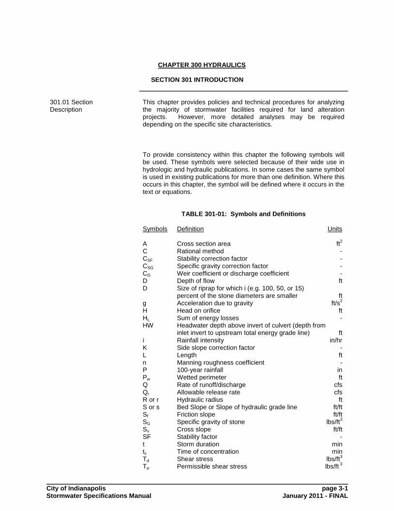
To provide consistency within this chapter the following symbols will
be used. These symbols were selected because of their wide use in hydrologic and hydraulic publications. In some cases the same symbol is used in existing publications for more than one definition. Where this occurs in this chapter, the symbol will be defined where it occurs in the text or equations.
TABLE 301-01: Symbols and Definitions Symbols Definition Units A Cross section area ft
2
C Rational method - CSF Stability correction factor - CSG Specific gravity correction factor - CD Weir coefficient or discharge coefficient - D Depth of flow ft D Size of riprap for which i (e.g. 100, 50, or 15)
percent of the stone diameters are smaller ft g Acceleration due to gravity ft/s
2
H Head on orifice ft HL Sum of energy losses - HW Headwater depth above invert of culvert (depth from
inlet invert to upstream total energy grade line) ft i Rainfall intensity in/hr K Side slope correction factor - L Length ft n Manning roughness coefficient - P 100-year rainfall in Pw Wetted perimeter ft Q Rate of runoff/discharge cfs Qr Allowable release rate cfs R or r Hydraulic radius ft S or s Bed Slope or Slope of hydraulic grade line ft/ft Sf Friction slope ft/ft SG Specific gravity of stone lbs/ft
3
Sx Cross slope ft/ft SF Stability factor - t Storm duration min tc Time of concentration min Td Shear stress lbs/ft
3
Tp Permissible shear stress lbs/ft 3

City of Indianapolis page 3-2 Stormwater Specifications Manual January 2011 - FINAL
T Channel top width ft TW Tailwater depth ft v Velocity ft/s Vol, or V Volume ft
3
Vf Huff storm factor
SECTION 302 DETENTION/RETENTION DESIGN
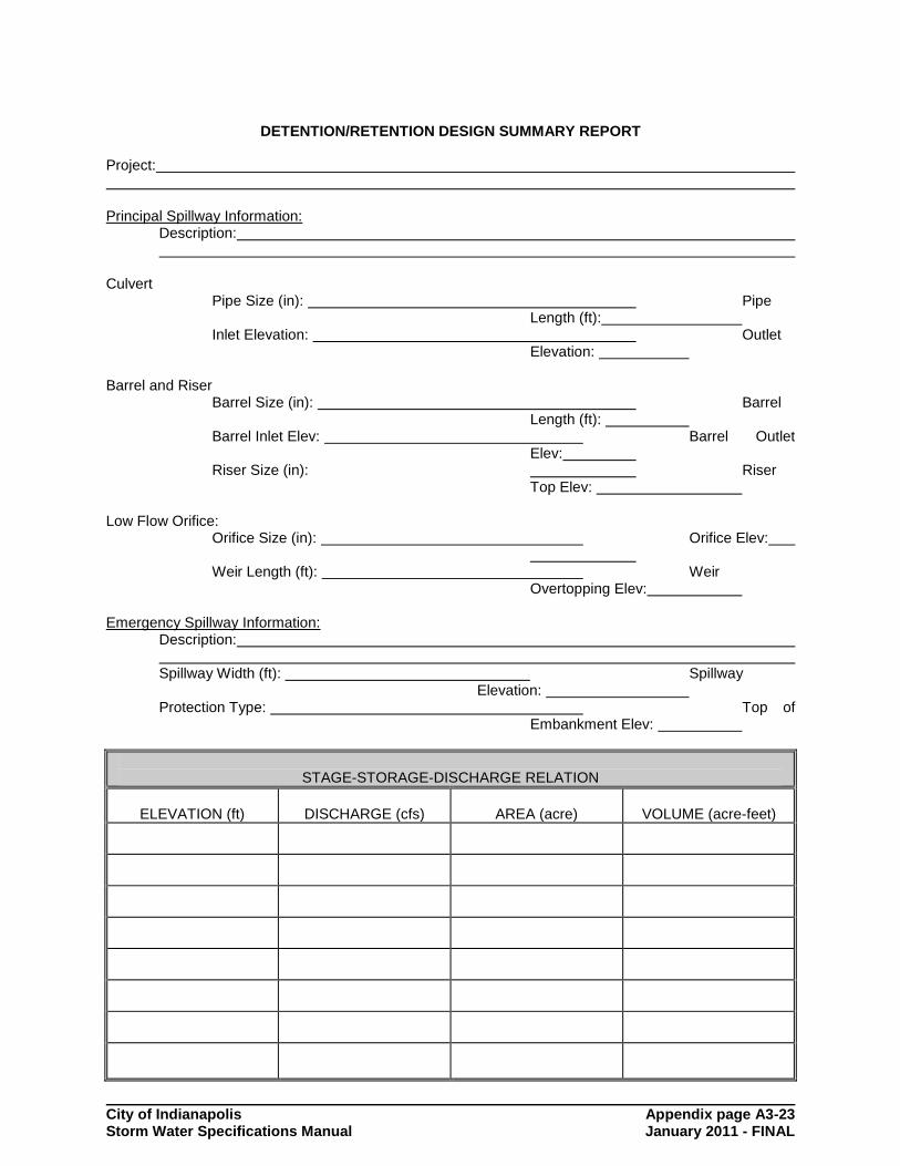
302.01 Introduction The design methods and criteria outlined within this section shall be used in the design and evaluation of detention/retention systems within the jurisdictional boundaries of this Manual. All designs must be supplemented with a detention/retention design summary report. A sample detention/retention design summary report is provided by Figure 302-1.
302.02 The Requirement for Detention/Retention
Detention/retention shall be required on all new developments except: 1. those identified in Chapter 200, section 201.06; or 2. where downstream mitigation efforts are accepted in lieu of
detention/retention. The figure below shows the logical steps in considering the need for detention/retention:
STEP 1: Is detention/retention required according to 201.06? If it is not the designer skips any consideration of downstream analysis or detention / retention. If detention/retention is required the designer proceed to step 2. The downstream analysis must assess each outflow point from the site separately.
Detention Required?
No Out
Yes
Is Site < 5 Acres
Want to do D/S Analysis?
Over Design Detention Basin
Yes No
Perform D/S Analysis
No Yes
Pre/Post Flow Analysis
Design Detention
Design D/S Mitigation
Modify Site Design
Pass Out
Fail

City of Indianapolis page 3-3 Stormwater Specifications Manual January 2011 - FINAL
STEP 2: Are any individual potential detention/retention sites draining areas less than 5 acres total including off-site drainage? If so the designer has the option as to whether or not to perform downstream analysis. There may be good reasons to avoid downstream analysis in favor of increased detention design. If "NO" the designer performs an oversized detention/ retention design and proceeds with the design. If "YES" the designer goes to Step 3 STEP 3: The designer performs a downstream capacity analysis for the storm frequencies required for the stormwater facilities encountered downstream. This will normally require the 10-, 25- and 100-year storms. STEP 4: The designer next performs the pre / post development discharge analysis described in Section 302.03. If the flows "PASS" the designer does not need to provide detention/retention, mitigation or site design modification. STEP 5: If the site “FAILS” the flow test or if there is inadequate downstream capacity for the post-development discharge the designer performs one or a combination of detention/retention design, downstream stormwater facility mitigation and/or site modification.
302.03 Minimum Performance Level of Detention/Retention Facilities
The design criteria for detention/retention are: 1. The minimum hydraulic performance levels and accepted design
methodologies for detention/retention basins shall conform to the following:
Q=Q ep 225.0
Q=Q ep 10105.0
Q=Q ep 102575.0
Q=Q ep 10100
where:
Q2e = 2 year discharge rate, existing conditions Q10e = 10 year discharge rate, existing conditions Q2p = 2 year discharge rate, developed conditions Q10p = 10 year discharge rate, developed conditions Q25p = 25 year discharge rate, developed conditions Q100p = 100 year discharge rate, developed conditions
2. Local basins are those which have a total land area contributing flow to the detention/retention basin, including on-site and off-site areas, of less than five (5) acres. Local basin designs in which the designer elects to over design the detention basin in lieu of performing downstream analysis, may be designed using the Modified Rational method as set forth herein. All other detention/retention designs shall use runoff hydrographs and routing techniques.
3. Regional basins are those which have a total land area contributing flow to the basin, including on-site and off-site areas, of five (5) acres or larger. In addition to the discharge rate

City of Indianapolis page 3-4 Stormwater Specifications Manual January 2011 - FINAL
requirements above, the following velocity requirements shall apply for regional basins:
V=V ep 22
V=V ep 1010
V=V ep 1025
V=V ep 10100
where:
V2e = 2 year velocity, existing conditions V10e = 10 year velocity, existing conditions V2p = 2 year velocity, developed conditions V10p = 10 year velocity, developed conditions V25p = 25 year velocity, developed conditions V100p = 100 year velocity, developed conditions
All regional detention/retention designs shall use runoff hydrographs and routing techniques.
4. When computing the discharges for detention/retention basin
design the entire upstream area that contributes runoff to the design point must be included in the computations. Areas that are bypassed for all levels of flow are the only allowable reductions in drainage area.
302.04 Increased Detention/Retention In Lieu Of Downstream Analysis
For local basins an increased level of detention/retention may be used in lieu of the downstream analysis described in Chapter 200, sections 201.05 through 201.06. If this option is selected, the design shall conform to the requirements for a local basin plus:
The stormwater runoff from all impervious area on the site shall be routed through the detention/retention facility, unless otherwise approved.
Stormwater flows shall not be diverted to downstream facilities
which do not accept runoff from the developing property under existing conditions.
Minor collector swales located within residential or commercial
developments, or collector swales located within open land uses such as agricultural fields, golf courses, and parks and recreation areas, as examples, will not be considered acceptable outfalls for a detention/retention providing this level of runoff control, unless a low flow system with an underdrain is installed downstream to convey trickle flows from these basins.
The Modified Rational method, discussed in the next section, may be used for sizing this type of detention pond since downstream analysis is not required. Standard routing design may also be used even though downstream analysis is not done.

City of Indianapolis page 3-5 Stormwater Specifications Manual January 2011 - FINAL
302.05 Modified Rational Method
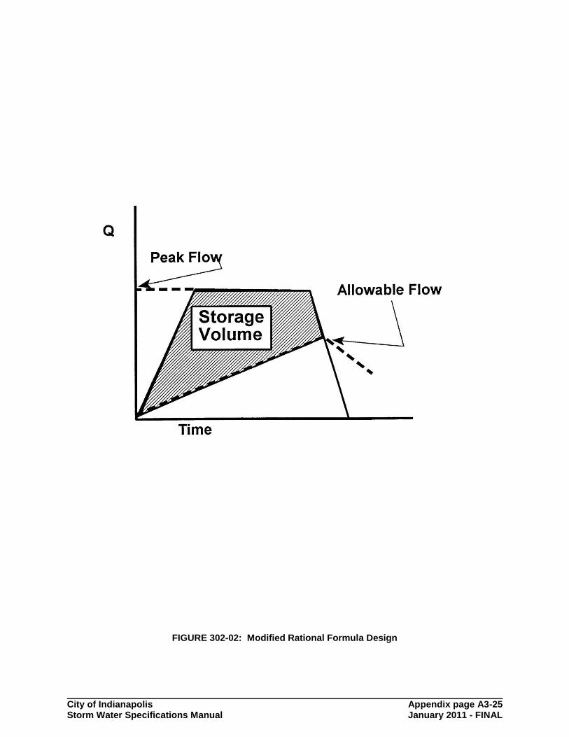
The Modified Rational Method may be used for the sizing of local detention/retention basins where downstream analysis is not required, as described in this section. The method approximates the required storage volume of the detention basin during the storm event. In addition the hydrograph shape is trapezoidal to approximate the shape of other hydrologic methods. Figure 302-2 illustrates the hydrograph and basin outflow. The general equation for the storage volume for this method is:
/2])t+(tQ-60[CiAt=Vol cR (Equation 302.01)
where:
Vol = required volume of the pond (cubic feet) C = post development C factor i = rainfall intensity from the IDF curve (in/hr) A=Area QR= allowable release rate t = storm duration to maximize the storage volume (minutes) tc = post-developed time of concentration (minutes)
To properly design a retention/detention basin system two critical design criteria must be applied. These two design criteria are the 100-year post developed peak flow controlled to the 10-year pre-developed peak flow levels and the 2-year post-developed peak flow controlled to 50 percent of the 2-year pre-developed peak flow levels. It should be noted, that for this method to give accurate results comparable to those found for routing of hydrographs, accurate estimates of the pre-development peak flows using the Rational Method must be made. The runoff coefficients given in Table 204.01 are conservative for peak flow design in that they are at the high end of the range of values possible for undeveloped conditions. While this provides a measure of conservatism for peak flow conveyance structures, it is very non-conservative for detention design where values at the low end of the range are more applicable. Therefore the following C values (called CR) are to be used to determine the pre-development allowable release rates (QR) for detention design for the Modified Rational Method. These values are to be used only for pre-development conditions for the Modified Rational Method detention design, not for peak flow calculations for stormwater conveyance facilities such as storm drains or culverts.
CR Factors for Allowable Release Rates for Modified Rational Detention Design
Hydrologic Soil
Group B Hydrologic Soil
Group C
Slope % 0 - 2 2 - 7 0 - 2 2 – 7
2 Year 0.03 0.03 0.03 0.03
10 year 0.03 0.04 0.11 0.13
Thus, for the 10-year pre-development allowable release rate the equation for QR is CR i10 A. And for the 2-year pre-development allowable release rate the equation for QR is 0.5 CR i2 A (allowing for fifty percent of the 2-year flow).

City of Indianapolis page 3-6 Stormwater Specifications Manual January 2011 - FINAL
Equation 302.01 can be combined with a form of the IDF curve equations, derivatives taken and set to zero and resubstitution done. The result is two equations that can be used to size a detention/retention basin for both design criteria. Contact the Department for more information on the method's derivation. To control the 100-year post-development peak flow to the 10-year pre-developed peak flow Equation 302.02 should be used to determine the critical duration, the time at which the storage volume is maximized.
b - Q
2CAab = t
R
c (Equation 302.02)
where:
C=developed condition C factor tc = critical storm duration (minutes) a = constant for 100-year storm event in Indianapolis = 222.37 b = constant for 100-year storm event in Indianapolis = 18.48 QR =allowable release rate, cfs
The maximum required volume for the 100-year post-developed to 10-year pre-developed design can be found using Equation 302.03.
)]t-(b2
Q+)CabAQ(2-60[CAa=V c
R1/2
Rmax
(Equation 302.03)
where: Vmax = required storage volume (cubic feet) and all other variables are as previously defined. In a similar fashion, the preceding formulas should be used to size a 2-year storm event orifice and storage volume. These 2-year values (storage volume and allowable peak outflow) can be used to compute a smaller 2-year orifice with an overtopping weir wall placed in front of the 10-year orifice. The designer should exercise care to ensure that the weir wall is not more restrictive than the 10-year orifice. The critical duration for this design criteria, the time at which the storage volume is maximized, can be found solving Equation 302.02 with the following variable definitions:
a = constant for 2-year storm event in Indianapolis = 91.28 b = constant for 2-year storm event in Indianapolis = 14.92
The maximum required volume for the 2-year post-developed peak flow to fifty percent of the 2-year pre-developed peak flow design can be found using Equation 302.03 with the appropriate 2-year design constants and release rate. The results of these prior computations are two sets of data. The first is the required storage volume and associated allowable outflow for the
City of Indianapolis page 3-7 Stormwater Specifications Manual January 2011 - FINAL
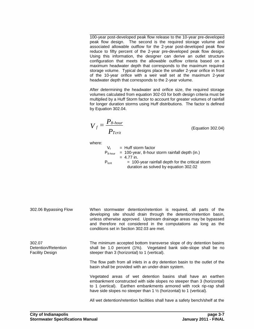
100-year post-developed peak flow release to the 10-year pre-developed peak flow design. The second is the required storage volume and associated allowable outflow for the 2-year post-developed peak flow reduce to fifty percent of the 2-year pre-developed peak flow design. Using this information, the designer can derive an outlet structure configuration that meets the allowable outflow criteria based on a maximum headwater depth that corresponds to the maximum required storage volume. Typical designs place the smaller 2-year orifice in front of the 10-year orifice with a weir wall set at the maximum 2-year headwater depth that corresponds to the 2-year volume. After determining the headwater and orifice size, the required storage volumes calculated from equation 302-03 for both design criteria must be multiplied by a Huff Storm factor to account for greater volumes of rainfall for longer duration storms using Huff distributions. The factor is defined by Equation 302.04.
P
P=V
Tcrit
hour-8f (Equation 302.04)
where:
Vf = Huff storm factor P8-hour = 100-year, 8-hour storm rainfall depth (in.)
= 4.77 in. Ptcrit = 100-year rainfall depth for the critical storm
duration as solved by equation 302.02
302.06 Bypassing Flow When stormwater detention/retention is required, all parts of the developing site should drain through the detention/retention basin, unless otherwise approved. Upstream drainage areas may be bypassed and therefore not considered in the computations as long as the conditions set in Section 302.03 are met.
302.07 Detention/Retention Facility Design
The minimum accepted bottom transverse slope of dry detention basins shall be 1.0 percent (1%). Vegetated bank side-slope shall be no steeper than 3 (horizontal) to 1 (vertical). The flow path from all inlets in a dry detention basin to the outlet of the basin shall be provided with an under-drain system. Vegetated areas of wet detention basins shall have an earthen embankment constructed with side slopes no steeper than 3 (horizontal) to 1 (vertical). Earthen embankments armored with rock rip-rap shall have side slopes no steeper than 1 ½ (horizontal) to 1 (vertical). All wet detention/retention facilities shall have a safety bench/shelf at the

City of Indianapolis page 3-8 Stormwater Specifications Manual January 2011 - FINAL
normal pool level. The safety bench shall have a minimum width of ten (10) feet and a slope no steeper than 4 (horizontal) to 1 (vertical). If a retaining wall adjoins the normal pool of a wet detention pond the wall shall have either steps or a ladder incorporated into the construction at the center of the wall span. When retention facilities are designed information must be provided on the plans that supports the ability of the structure to retain water, including the soil types on the site and a geologist‟s report showing how the site will infiltrate water. Minimum normal depth of a wet pond, calculated as the deepest point in the pond, shall be eight (8) feet. The maximum ponding depth for parking lot detention shall be seven (7) inches for the 100-year storm event runoff from the entire contributing watershed. Proper operations and maintenance practices for all detention/ retention structures and their appurtenances, such as emergency spillways, will be identified in the Operations and Maintenance Manual, as required in Section 102.06.
302.08 Design of Detention/Retention Facility Emergency Spillways
Emergency spillways shall be capable of handling one and one-quarter times (125%) the inlet peak discharge and peak flow velocity resulting from the 100-year design storm event runoff from the entire contributing watershed, assuming post-development conditions, draining to a detention/retention facility. However, engineering judgment may dictate use of a higher design standard. Many types of emergency spillways are allowable provided adequate provision is made for the discharge of the flow through the facility and a minimum freeboard of one-foot (1) is provided for larger regional ponds above the maximum anticipated flow depth through the emergency spillway. All emergency spillways shall outlet to an easement containing a channel with acceptable capacity. All calculations, easement delineation, and cross sections for the emergency spillway are to be submitted for review.
302.09 Outlet Hydraulics - Orifice Flow
The outlet hydraulics of a detention/retention basin typically consists of two types of flow, orifice and weir flow. The basic equation for determination of orifice flow is as follows:
2gHAC=Q D (Equation 302.01)
where:
Q = peak discharge rate, cfs CD = coefficient of discharge, dimensionless A = cross sectional area of orifice, square feet g = acceleration due to gravity (32.2 ft/sec/sec) H = head on the orifice, feet.
City of Indianapolis page 3-9 Stormwater Specifications Manual January 2011 - FINAL
The value of H is determined by different methods depending upon the location of the water surface as follows: Free Discharge: H is the difference in elevation between
upstream water surface and center of flow of the orifice.
Submerged Orifice: H is the difference in elevation between
upstream and downstream water surfaces. The value of the coefficient of discharge CD is a function of the size and shape of the orifice, the head on the orifice, the sharpness of the orifice's edge, the roughness of the inner surface, and the degree to which the contraction of flow is suppressed (Reference King's Handbook of Hydraulics). A nominal value of 0.60 may be used for the standard types of orifices and head ranges used for outlet control structures, however, sound engineering judgment must be used in the practical application of this value.
302.10 Outlet Hydraulics – Weir Flow
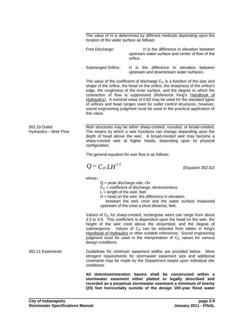
Weir structures may be either sharp-crested, rounded, or broad-crested. The means by which a weir functions can change depending upon the depth of head above the weir. A broad-crested weir may become a sharp-crested weir at higher heads, depending upon its physical configuration. The general equation for weir flow is as follows:
LHC=Q 1.5D (Equation 302.02)
where:
Q = peak discharge rate, cfs CD = coefficient of discharge, dimensionless L = length of the weir, feet H = head on the weir, the difference in elevation between the weir crest and the water surface measured upstream of the crest a short distance, feet.
Values of CD for sharp-crested, rectangular weirs can range from about 3.3 to 4.9. This coefficient is dependent upon the head on the weir, the height of the weir crest above the streambed, and the degree of submergence. Values of CD can be selected from tables in King's Handbook of Hydraulics or other suitable references. Sound engineering judgment must be used in the interpretation of CD values for various design conditions.
302.11 Easements Guidelines for minimum easement widths are provided below. More stringent requirements for stormwater easement size and additional covenants may be made by the Department based upon individual site conditions. All detention/retention basins shall be constructed within a stormwater easement either platted or legally described and recorded as a perpetual stormwater easement a minimum of twenty (20) feet horizontally outside of the design 100-year flood water

City of Indianapolis page 3-10 Stormwater Specifications Manual January 2011 - FINAL
elevation of the basin. All emergency spillways will have an easement that extends from the crown of the emergency spillway structure to the point where the spillway enters the downstream drainage system. Public street rights-of-ways will not be acceptable areas for construction of detention/retention facilities, unless otherwise approved by this Department.
SECTION 303 OPEN CHANNEL DESIGN
303.01 Introduction
Open channel flow may be evaluated utilizing Manning's equation, however, restrictions within open channels, such as at open culverts or storm drains, may be required to be evaluated by more sophisticated design methods such as the direct-step backwater or reservoir routing techniques.
303.02 Easements/Minimum Flood Protection Elevations
Hydraulic and hydrologic computations must be performed to determine the maximum inundated area resulting from the 25-year design storm event runoff. No habitable structures may be located within this area. For areas which drain more than 5 acres:
easements must be dedicated which encompass the entire delineated 25-year flood area;
additional hydraulic and hydrologic calculations must be performed to determine the maximum inundated area resulting from the 100-year design storm event runoff
a 100-year flood line must be delineated in addition to the 25-year easement restriction.
The lowest location of any proposed habitable structures where water may enter must be located above this delineated 100-year flood elevation. Collector Surface water collector swales within the rear yard and side Swales yard areas of residential subdivisions, on all
non-residential parcels, and for all bypassed flow conveyances shall be constructed within a drainage easement possessing a minimum width of twenty (20) feet. For residential properties the drainage swale should be generally constructed approximately in the middle of the easement.
Open Ditches Open ditches, those which do not have grass bottoms or
are not accessible to vehicular traffic within the ditch, shall be placed within a drainage easement of a minimum width of ten (10) feet from the top of one bank of the channel.
Flood Properties located within the regulatory floodway or Protection floodway fringe area shall provide floodway/floodway

City of Indianapolis page 3-11 Stormwater Specifications Manual January 2011 - FINAL
Grades fringe boundary delineations on the site plan. A citation of the regulatory source for these boundary delineations and minimum lowest enclosed floor elevations of permanent structures shall be provided on the site plan. Additional requirements for completing alterations to the land or existing structures within regulatory flood hazard areas may be found within the Flood Control District Zoning Ordinance for Marion County, Indiana, which may be found within the Appendix of Section 100 of this Manual.
Floodplain management shall be in accordance with the adopted floodplain regulations. The City of Indianapolis has adopted floodplain regulations through the Flood Control District Zoning Ordinance of Marion County, Indiana. A copy of the effective Flood Control District Zoning Ordinance has been included within the appendix of Chapter 100. In addition to these regulations, the following specific requirements and other applicable requirements found or stated in this manual shall apply: 1. Structures located in a Flood Control Zoning District established
and regulated by effective Flood Control Districts Zoning Ordinance of Marion County, Indiana, shall conform with all applicable standards and requirements of said Ordinance.
2. Structures to be constructed that are not located in a flood control
district regulated by the Flood Control Districts Zoning Ordinance of Marion County, Indiana, shall conform with the following requirements:
a. The first finished floor of new structure to be constructed
adjacent to a surface drainage feature which drains areas between 150 and 640 acres shall be located at an elevation at least two feet above the maximum 100-year water surface elevation. The 100-year water surface elevation may be established through the use of a single cross-section analysis.
b. The lowest enclosed area of any structure located adjacent to
surface drainage features which drain areas greater than 640 acres or which is located within a Flood Control Zoning District established by the effective Flood Control Districts Zoning Ordinance of Marion County, Indiana, for which the effective Federal Emergency Management Agency Flood Insurance Study for the City of Indianapolis does not establish 100-year water surface elevations, shall be located at an elevation which is at least two feet above the maximum 100-year water surface elevation. The 100-year water surface elevation shall be established:
(1) By a site specific recommendation from the Indiana
Department of Natural Resources; or
(2) Through a site-specific engineering analysis performed in accordance with regulations adopted by the Board of Public Works; and where applicable
City of Indianapolis page 3-12 Stormwater Specifications Manual January 2011 - FINAL
(3) In conformance with the effective Flood Control Districts Zoning Ordinance of Marion County, Indiana
303.03 Grading and Depth of Open Channels / Swales
Except for road side ditches, the side-slope of grass lined channels shall be no steeper than 3 (horizontal) to 1 (vertical). When the bottom width of trapezoidal grass-lined channels exceeds fifteen (15) feet, rock rip-rap or paved low flow channels shall be provided to convey low flows and to prevent meandering. For grass-lined channels, intended to convey continuous trickle flows such as for retention pond outlets, an enclosed storm drain, subsurface tile with gravel envelope, rock rip-rap, or paved low flow channel will be required. The rock used in side-slope rip-rap shall be no smaller than 6 inches. The side-slope of rock rip-rap lined open conveyance channels shall be no steeper than 1 ½ (horizontal) to 1 (vertical), unless otherwise approved. To prevent chronic wetness in the invert of open channels, subsurface tiles shall be installed a minimum of 1 ½ feet in depth (from the tile invert), with a #8 gravel or equivalent size washed stone as a granular envelope, as follows:
Minor drainage collector swales in rear yards and between homes shall possess a maximum channel length of 400 lineal feet and no off-site water, unless subsurface tile is also provided. The required channel slope and invert treatment for minor drainage collector swales shall be as follows: swales shall be grass lined; subsurface drainage tile shall be required if the channel slope is less than 2.0%; and, the minimum channel slope shall be 0.3%.
For basement residential lots a “tee” should be provided in the rear lot line’s subsurface drain for the purpose of discharging sump pump water directly into the drain.
For relatively large open channels and perennial streams, minimum channel slopes and the provision of subsurface drainage shall be approved on a case basis by the Department.
Privately owned open channels, including man-made ditches, swales, and natural streams, shall be repaired and/or reconstructed such that all woody vegetation has been cleared, and the channel banks are properly stabilized to prevent present and future erosion.
303.04 Channel Lining Design Requirements
The peak discharge from the 10-year design storm event shall be used to design channel linings for all channels. The final design of open channels should be consistent with permissible shear stress (τp) for the selected channel lining. Reference should be made to the publication FHWA-RD-89-110, HEC-15 for a more detailed description of this analysis. Permissible shear stress for various channel linings are reported in Table 303-1, Figure 303-1 and Figure 303-2.

City of Indianapolis page 3-13 Stormwater Specifications Manual January 2011 - FINAL
The process of channel lining design is as follows: • Select a lining and determine the permissible shear stress (τp), in
lbs/ft2, from Table 303-1, Figure 303-1 and 303-2.
• Choose an initial Manning‟s "n" value based on engineering
reference books, such as "Open-Channel Hydraulics" by V.T. Chow.
• Calculate normal flow depth (D), in ft, at design discharge using
Manning‟s Formula. • Compute maximum shear stress (Td), in lbs/ft
2, at normal depth
as:
SD62.4=T d (Equation 303.01)
where:
Td = maximum shear stress (lbs/ft3)
d = normal flow depth (ft) S = channel gradient (ft/ft)
• If Td < Tp, then the channel lining is acceptable. Otherwise
consider the following options.
choose a more resistant lining
Use gabions, or other more rigid lining either as full lining or composite
decrease channel slope
decrease slope in combination with drop structures
increase channel width and/or flatten side slopes For channel designs incorporating a riprap lining, the following procedures shall be used. Riprap shall not be placed on a side slope steeper than 1.5H:1V unless otherwise approved. The toe of the riprap shall be extended below the channel or ditch bed a minimum distance of one (1.0) foot or 1.5 D50 (which ever is greater) except where alternate methods are approved or where the ditch or channel bottom is also covered with riprap. Filter fabric or a filter course of gravel should be placed under the stone for larger drainage channels. For normal channel design riprap can be sized using a method developed by the Federal Highway Administration and slightly modified for use here. Equation 303.02 gives the D50 size of stone (in inches) for riprap placed in a channel with average velocity "v" and depth "D".
KD/v0.0136=D1.50.53
50 (Equation 303.02)
K is the side slope correction factor and can be found from equation 303.03 and shall be used for all side slope placement on slopes steeper then 4H:1V. For other placement K is equal to one (1.0). θ is equal to the bank angle with the horizontal (e.g. a 1V:3H slope has a θ value of 18.43 degrees).
City of Indianapolis page 3-14 Stormwater Specifications Manual January 2011 - FINAL
]/0.396)(-[1=K0.52
sin (Equation 303.03)
Equation 303.02 is based on a safety factor of 1.2 and a stone weight of 165 lbs/ft
3. For situations other than a uniform straight channel the D50
size from equation 303.02 should be multiplied by a Stability Correction Factor found in the table below and used in equation 303.04. Condition
Stability Factor
Uniform flow; straight or mildly curving reach (curve radius/channel topwidth (Rc/T > 30); little impact from wave action and floating debris; little uncertainty in design parameters. 1.0 -
1.2 Gradually varied flow; moderate bend curvature (30 > Rc/T > 10); moderate impact from waves or debris; moderate uncertainty in design parameters.
1.3 - 1.6
Approaching rapidly varied flow; sharp bend curvature (10 > Rc/T); significant impact from waves or debris, high flow turbulence; significant uncertainty in design parameters. 1.6 -
2.0
)(SF/1.2=C1.5
SF (Equation 303.04)
where:
SF = stability factor CSF = stability correction factor
If the rock density is significantly different from 165 lbs/ft
3 the D50 size
found in equation 303.02 should be multiplied by a specific gravity correction factor (CSG) found in equation 303.05. SG is the specific gravity of the stone (stone weighing 165 lbs/ft
3 has a specific gravity of
about 2.65).
]1)-S[1.65/=C1.5
GSG (Equation 303.05)
where:
SG = specific gravity of stone, lbs/ft3
CSG = specific gravity correction factor

City of Indianapolis page 3-15 Stormwater Specifications Manual January 2011 - FINAL
The riprap layer thickness shall be a minimum of D100, and the D85/D15 value shall be less than 4.6. Stone shall be angular in shape. Riprap shall be placed so as not to be flanked by the flow. The end of the protected section should be keyed into the bank to prevent scouring failure. For riprap blanket thicknesses greater than D100 the following reductions in D50 stone size are allowed:
for blanket thickness equal to 1.5 D100 the D50 size can be reduced 25 percent.
for blanket thickness equal to 2.0 D100 the D50 size can be reduced 40 percent.
Channel design must account for riprap thickness in channel excavation. Channel roughness for riprap lined channels can be evaluated from (D50 in feet):
)D0.0395(=n1/6
50 (Equation 303.06)
303.05 Design of Open Channels Using Manning's Equation
Manning's Equation may be used to size proposed open channels where backwater effects created by obstructions within the channel, or elevated tailwaters, as examples, are not of concern. Manning's Equation may be solved directly from its standard form as follows:
SRAn
1.49=Q 1/22/3
(Equation 303.07)
and iterated as necessary with various values of channel geometry to obtain the desired values of flow quantity, velocity, and depth. Engineering reference books, such as "Open-Channel Hydraulics" by V.T. Chow may be used as a guide for Manning's "n" values. Figure 303-3 provides examples of typical open channel cross-sectional configurations and contains the geometric elements of common channel sections required to determine the channel area (A), wetted perimeter (Pw), and hydraulic radius (R = A/Pw).
SECTION 304 CULVERTS/BRIDGES 304.01 Introduction The design methods and criteria outlined or referred to within this section
shall be used in the design and evaluation of culvert systems within the jurisdiction of this Manual. Computer models such as Federal Highway Administration's HY-8 may be used to perform culvert/bridge design computations. The design of culverts can be quite complex. Therefore only introductory material is presented herein. The designer is referred to Federal Highway Administration publication Hydraulic Design Series No.5 (HDS-5), "Hydraulic Design of Highway Culverts", Report No. FHWA-IP-85-15, for a complete treatment. Methods contained in HDS-5 shall be used for the design of culverts.
City of Indianapolis page 3-16 Stormwater Specifications Manual January 2011 - FINAL
304.02 Allowable Headwater
Open culverts shall be designed to safely pass the peak discharge from the 25-year design storm event runoff from the entire contributing watershed without inundating any portion of the crossing or approach roadway. An easement must be recorded for the 25-year storm event flow areas. During the 100-year storm event, road overflow shall not exceed seven (7) inches above the centerline crown elevation of the roadway. The 100-year storm event must be checked to determine the flooded area so that a building restriction line can be shown on a record plat. The lowest elevation where water may enter any adjacent structures must be outside this delineation.
304.03 Open Culverts Open culverts shall be sized utilizing orifice and weir flow equations where applicable for individual site conditions and storm frequencies. Inlet and outlet control nomographs for evaluation of open culvert hydraulics may also be utilized to evaluate culvert hydraulics, and have been provided in HDS-5 referred to above. Open culverts which pose a threat of damage to property or a hindrance of public services due to backwater and/or road overflow shall be analyzed utilizing the direct-step backwater method or reservoir flood routing techniques for determination of the depth of flow over the culvert/roadway during the peak discharge from the 100-year design storm event, backwater elevations, downstream flow velocities and resulting channel scour impacts.
304.04 Culverts Operating Under Inlet Control
Inlet control for culverts may occur in two ways: Unsubmerged: Where the headwater depth is not sufficient to submerge the top of the culvert and the culvert inlet slope is supercritical. Under these conditions, the culvert inlet acts like a weir. Submerged: The headwater submerges the top of the culvert but the pipe does not flow full. Under these conditions the culvert inlet acts like an orifice. In the unsubmerged inlet condition, the equation governing the culvert capacity is the weir flow equation. In the submerged inlet condition, the equation governing the culvert capacity is the orifice flow equation. The nomographsprovided by Hydraulic Design Series No. 5, Report No. FHWA- Ip-85-15 may be used to determine culvert flow under inlet control conditions for common culvert materials. It should be noted by the designer that reinforced concrete pipe arch is not typically available within the Marion County or surrounding area.
304.05 Culverts Operating Under Outlet Control
Outlet control will govern in the design of open culverts when the headwater is sufficiently deep, the culvert slope sufficiently flat, and the culvert sufficiently long. There are five basic types of outlet control culvert flow conditions as depicted in Figure 304-2. Outlet control flow conditions can be calculated based on energy balance. The Bernoulli equation may be used to solve the culvert flow problem. It can be expressed in simplified form by the following
City of Indianapolis page 3-17 Stormwater Specifications Manual January 2011 - FINAL
equation:
H + T = HW LWO (Equation 304.01)
where:
HWO = Headwater depth above the outlet invert (ft) TW = Tailwater depth above the outlet invert (ft) HL = The sum of all the energy losses including: entrance loss, friction loss, exit loss, and losses for grates, bends, obstructions, etc.
Equation 304.01 is used to calculate the culvert capacity directly when the culvert is flowing under full flow conditions A, B or C demonstrated by Figure 304-2. Backwater calculations, beginning at the downstream tailwater elevation, may be required for conditions D or E. The downstream water surface elevation is based on the critical depth or tailwater elevation whichever is greater. Simplifications, modifications and nomographic solutions to this procedure are available in HDS-5.
304.06 Inlet/Outlet Losses
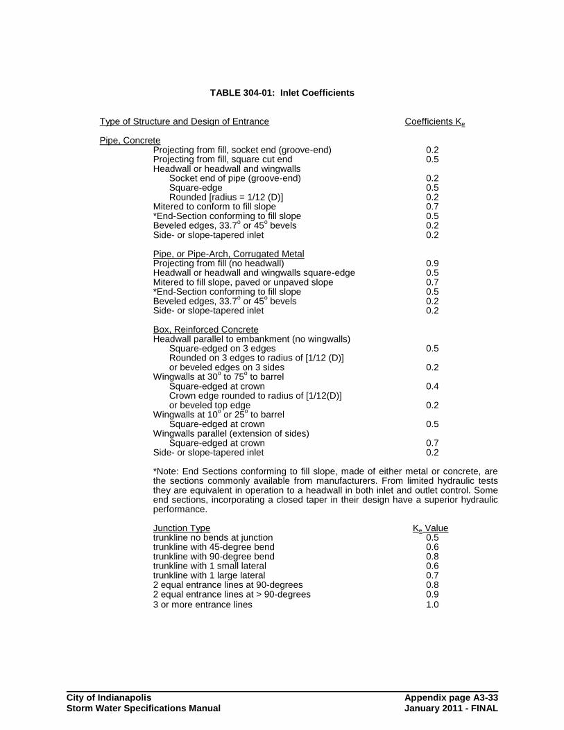
Selection of the inlet type is an important part of culvert design, particularly culverts with inlet control. Hydraulic efficiency and cost can be significantly affected by inlet conditions. The inlet coefficient Ke, is a measure of the hydraulic efficiency of the inlet, with lower values indicating greater efficiency. All methods described in this chapter, directly or indirectly, use inlet coefficients. Typical inlet coefficients are given in Table 304-1.
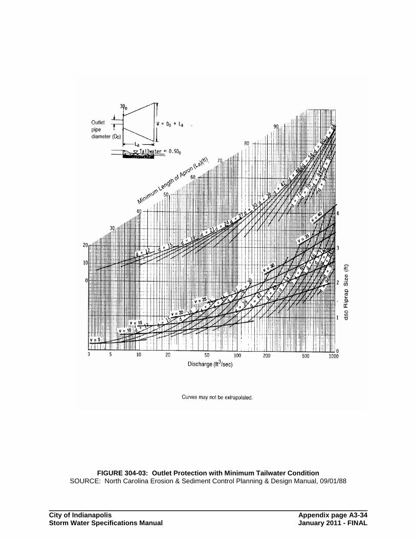
304.07 Outlet Protection/Energy Dissipation
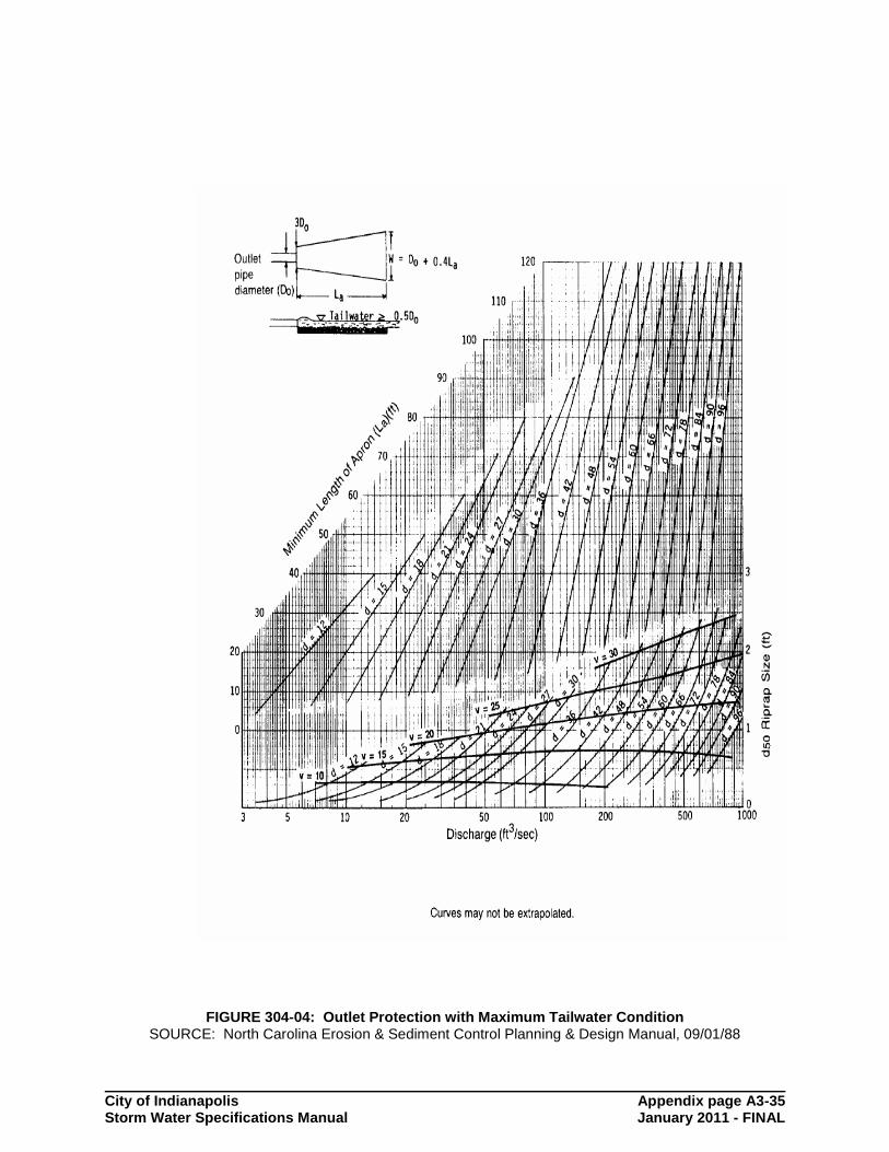
Energy dissipaters shall be employed whenever the velocity of flows leaving a storm water management facility exceeds the erosive velocity of the downstream channel system. The procedure presented in this section is taken from USDA, NRCS (SCS, 1975). Two sets of curves, one for minimum and one for maximum tailwater conditions, are used to determine the apron size and the median riprap diameter, D50. If tailwater conditions are known, or if both minimum and maximum conditions may occur, the apron should be designed to meet criteria for both. Although the design curves are based on round pipes flowing full, they can be used for partially full pipes and box culverts. The design procedure consists of the following steps: 1. If possible, determine tailwater conditions for the channel. If
tailwater is less than one-half the discharge flow depth (pipe diameter if flowing full), minimum tailwater conditions exist and the curves in Figure 304-3 apply. Otherwise, maximum tailwater conditions exist and the curves in Figure 304-4 should be used.
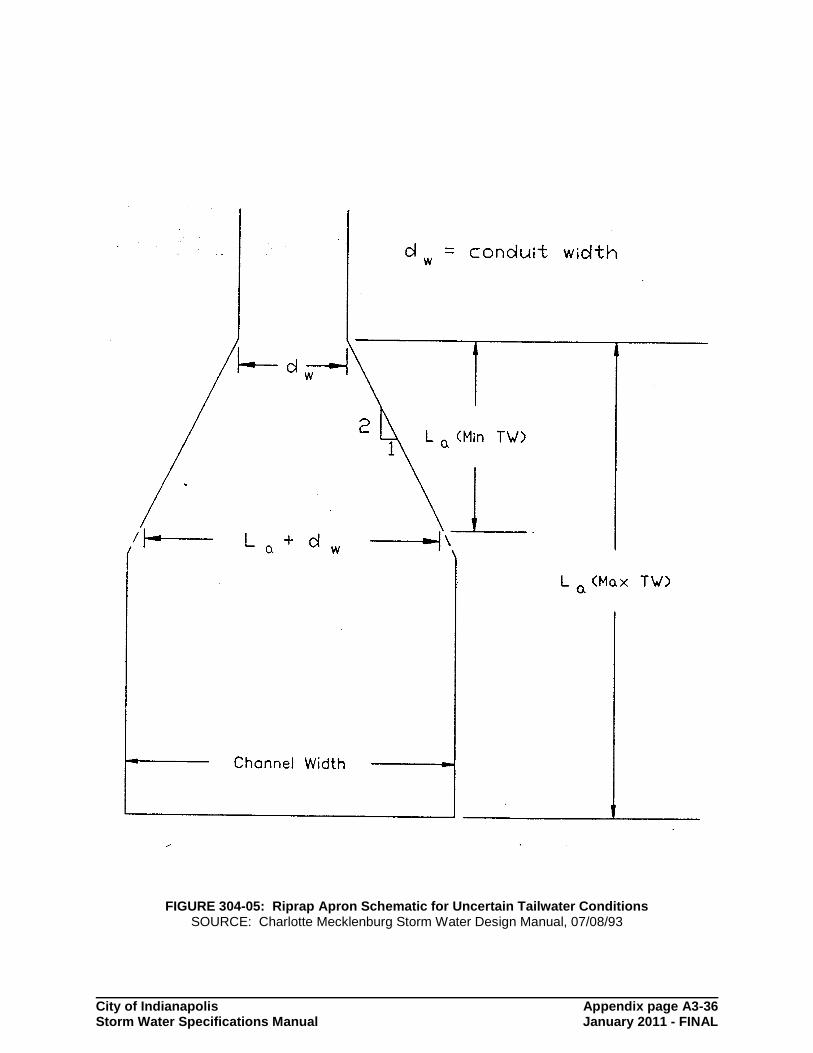
2. Determine the correct apron length and median riprap diameter,
d50, using the appropriate curves from Figure 304-3 and 304-4. If tailwater conditions are uncertain, find the values for both minimum and maximum conditions and size the apron as shown in Figure 304-5.
a. For pipes flowing full:
Use the depth of flow, d, which equals the pipe diameter, in feet, and design discharge, in cfs, to obtain the apron length, La, and median riprap diameter, d50, from the appropriate curves.

City of Indianapolis page 3-18 Stormwater Specifications Manual January 2011 - FINAL
b. For pipes flowing partially full:
Use the depth of flow, d, in feet, and velocity, v, in feet/second. On the lower portion of the appropriate figure, find the intersection of the d and v curves, then find the riprap median diameter, d50, from the scale on the right. From the lower d and v intersection point, move vertically to the upper curves until intersecting the curve for the correct flow depth, d. Find the minimum apron length, La, from the scale on the left.
SECTION 305 STORM DRAINS/INLETS 305.01 Introduction
Storm drain piping systems are networks of storm pipes, catch basins, manholes, inlets and outfalls designed and constructed to convey surface water runoff. The hydraulic analysis of flow within storm drain piping systems typically involves analysis of flow caused by the natural forces of gravity ("gravity flow"), and hydraulic analysis of systems under pressure flow conditions.
305.02 Easements Minimum easement widths are as provided below. More stringent requirements for stormwater easement size and additional covenants may be made by the Department based upon individual site conditions. 1. Storm Drains Depth of Drain From
Diameter of Minimum
Finish Grade To Crown Storm Drain Easement Width
3' or less
15" or less 15'
More than 3'
15" or less 20'
3' or less
Greater than 15" 20'
More than 3'
Greater than 15"
City of Indianapolis page 3-19 Stormwater Specifications Manual January 2011 - FINAL
25'
305.03 Storm Drain Pipe Design
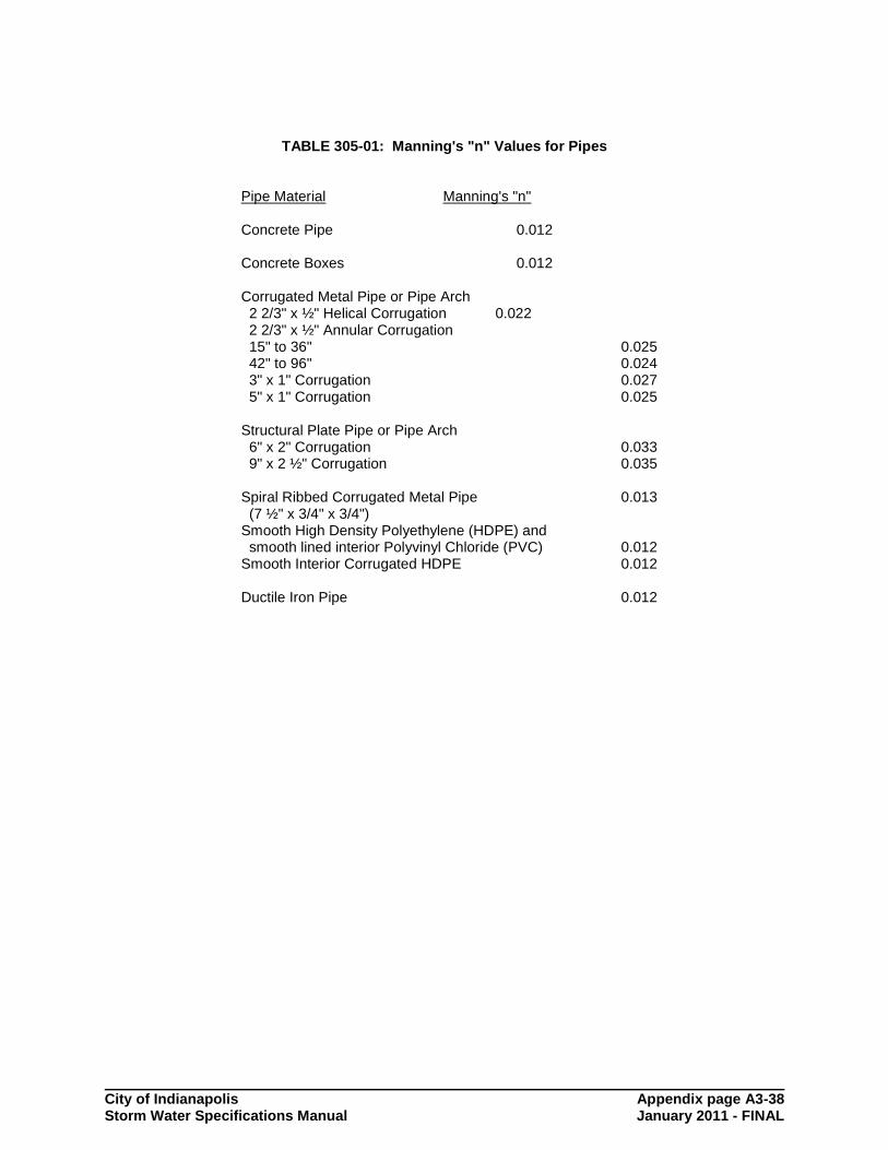
The use of Manning's equation shall be considered acceptable for determination of storm drain pipe sizes when the design discharge is ninety percent (90 %) or less of the capacity of a commercially available pipe as computed by Manning’s equation. The storm drain system must be capable of passing the 10-year storm event with free water surface elevations below the crown of the pipe. Design computations of storm drain pipe systems using the Rational Formula and Manning's equation shall be submitted with the stormwater permit application on the Storm Drain Flow Tabulation Form provided by Figure 305-1 or by suitable computer program output listing giving similar information. Typical Manning's "n" values for standard storm drain materials are provided in Table 305-1. Head loss computations shall be submitted with the stormwater permit application on the form provided by Figure 305-2. Proper operations and maintenance practices for all storm drain and inlet structures and their appurtenances will be identified in the Operations and Maintenance Manual, as required in Section 102.06.
305.04 Backwater Method for Pipe System Analysis
For hydraulic analysis of existing or proposed storm drains which possess submerged outfalls, a more sophisticated design/analysis methodology than Manning's equation will be required. Various computer modeling programs are available for analysis of storm drains under these conditions. These models must be approved by the Department. The backwater analysis method provides a more accurate estimate of pipe flow by calculating individual head losses in pipe systems which are surcharged and/or have submerged outlets. These head losses are added to a known downstream water surface elevation to give a design water surface elevation for a given flow at the desired upstream location. Total head losses may be determined as follows: Total head loss = frictional loss + manhole loss + velocity head loss
+ junction loss Frictional loss is computed from Manning's Equation expressed in the following form:
R2.22
(nv)=S
4/3
2
f (Equation 305.01)
where:
Sf = head loss per lineal foot of drain due to friction n = Manning's "n" v = Flow velocity in ft/sec = Q/A R = Hydraulic radius, ft. A/Pw
City of Indianapolis page 3-20 Stormwater Specifications Manual January 2011 - FINAL
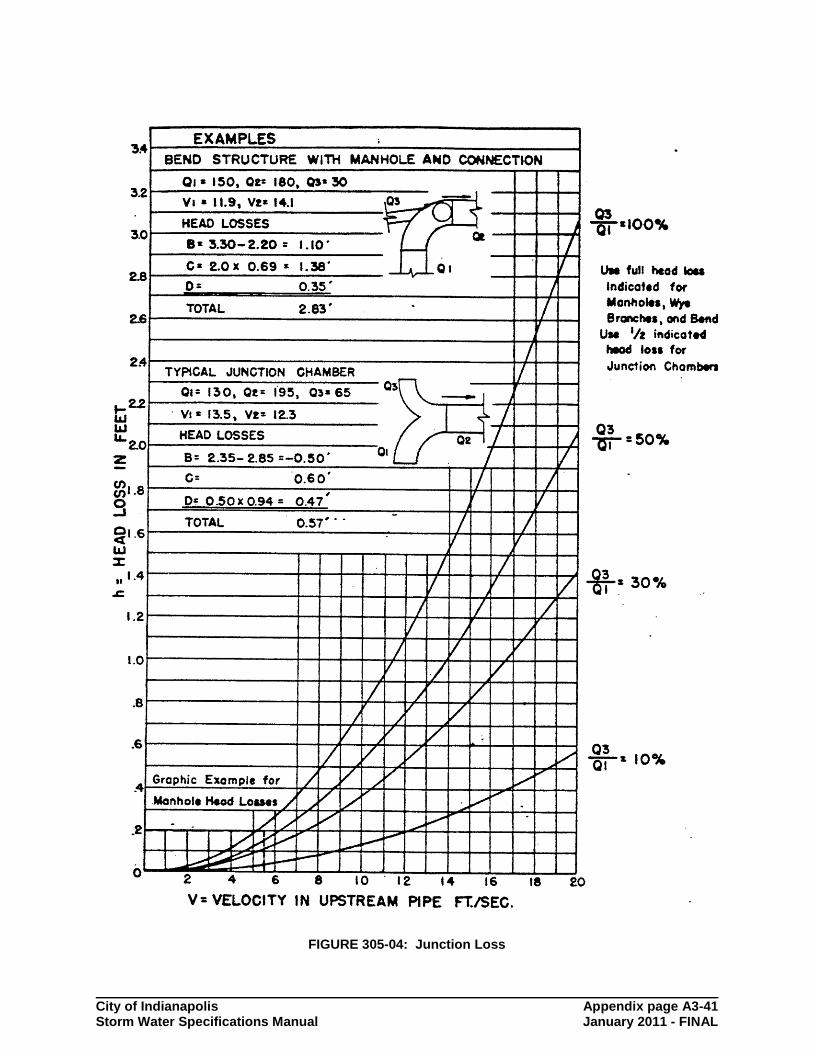
The remaining components of total head loss may be computed using standard equations, or they may be estimated using graphical solutions. Figures 305-3 and 305-4 present graphical solutions to losses in junction structures and in bends based on information provided by Baltimore County, MD. The curves are labeled "A", "B", "C" and "D". They are based on full flow in the pipes. The total loss at any junction is the sum of the applicable types of loss. The "A" loss is the entrance or exit loss. The larger of the velocities entering or leaving the structure is used to calculate the loss. The "B" loss is not really a loss but an expedient to handle the change in velocity head during hydraulic grade line calculations. It is always the downstream velocity head minus the upstream head with the algebraic sign preserved. Where the upstream velocity head is greater than the downstream head the apparent gains may be used to offset other head losses in the structure. However, the total head loss may not be less than zero. The "C" loss represents the bend loss and is based on the higher of the two velocities. The "D" loss is the junction or combined flow losses and relates only to the incoming velocity and varies with the ratio of the Q3 and Q1 as depicted in the Figure. Intermediate values of Q3/Q1 may be interpolated.
For cut-ins, wyes and preformed fittings use the full value of "B", "C" and "D" losses.
For manholes and inlets use the full value of all four types of losses for pipe diameters 30" and under. For larger pipe diameters omit the "A" loss since it is accounted for in the "C" loss.
For bends use the full value of the "B", "C" and "D" curves and increase the losses for special cases as stated on the figures.
For junction chambers use the full values of the "B" and "C" losses; use 50% of the indicated "D" loss. Increase the "C" loss 50% for junction chambers with manholes.
305.05 Minimum Velocity
Minimum storm drain flowing velocity for full pipe flow shall be 2.5 feet-per-second (fps). The minimum slope for storm drains equal to or larger than 48 inches in diameter shall be 0.001 feet/foot.
305.06 Non-Gravity Flow Systems
Stormwater facilities shall be designed to convey stormwater runoff by gravity flow unless otherwise approved by the department. Stormwater control systems that do not satisfy this goal would include stormwater pumping systems, and mechanical sluice gates, as examples. Design options that do not rely upon gravity flow may be approved as a variance of Chapter 561 of Indianapolis City Code, with documentation to the Department of the infeasibility and/or undue hardship required to install available gravity flow design options. As a minimum, the following additional information shall also be submitted with the stormwater permit application for non-gravity flow systems: 1. Identification of a lifetime maintenance schedule for the
non-gravity flow system.

City of Indianapolis page 3-21 Stormwater Specifications Manual January 2011 - FINAL
2. Covenants attached to the property deed which place sole
responsibility for maintenance of the non-gravity flow system with the current property owner of record.
3. An indemnification of the City relative to the non gravity-flow
design. Pumping systems, where approved, shall be designed using the hydraulic methods that apply to storm drain pump systems, set forth within standard engineering texts. Non-gravity flow systems shall be designed such that should the system fail, damage to adjoining properties and facilities will be limited to the site only.
305.07 Inlet Grate Design
The design methodology used to compute the flow capacity of storm drain inlet grates shall utilize orifice and weir flow equations outlined by these Standards, with consideration given to grate open areas, and flow dimensions provided by the casting manufacturer. The grate casting shall provide sufficient grate open area to convey the 10-Year storm event. The potential maximum depth to which stormwater may pond above the inlet grate must not threaten surrounding permanent structures and public facilities. Emergency overflow points shall be provided for inlets placed in a sumped condition. Roll curb and gutter inlet grates as a general rule shall be placed at a maximum interval of four-hundred (400) feet, provided a minimum 10-Year design storm flow capacity has also been provided. Conformance with additional requirements for design and placement of storm drain inlets within public streets and roads as set forth by the Indianapolis Department of Transportation will be required.
305.08 Gutterline Hydraulic Evaluation
Inlets in roadway gutter lines must be spaced to prevent flow from entering public road intersections. In addition, inlets should be spaced intermediately in residential street gutter lines to allow one lane (based on the lane width of the road) of traffic to remain open during the 100-year storm event. Multi-lane facilities may have one travel lane on each side of the roadway flooded during the 100-year storm event. The design storm for all of the conditions is the 10-year storm event. The allowable minor storm capacity of each street section may be calculated for flow in triangular gutter sections using the modified Manning's formula as follows:
T S S n
0.56 = Q 2.670.5
X
1.67
(Equation 305.02)
where:
Q = discharge, cfs SX = cross slope of the pavement (ft/ft) T = top width of water from vertical gutter face extending into the road, ft S = longitudinal grade of street (ft/ft) n = Manning's roughness coefficient

City of Indianapolis page 3-22 Stormwater Specifications Manual January 2011 - FINAL
The above equation may also be solved utilizing the nomograph provided in Figure 305-5. Further information on other gutter configurations can be found in Federal Highway Administration, "Drainage of Highway Pavements", FHWA-TS-84-202, Hydraulic Engineering Circular No. 12.
City of Indianapolis Appendix page A3-23 Storm Water Specifications Manual January 2011 - FINAL
DETENTION/RETENTION DESIGN SUMMARY REPORT Project: Principal Spillway Information:
Description:
Culvert
Pipe Size (in): Pipe Length (ft):
Inlet Elevation: Outlet Elevation:
Barrel and Riser
Barrel Size (in): Barrel Length (ft):
Barrel Inlet Elev: Barrel Outlet Elev:
Riser Size (in): Riser Top Elev:
Low Flow Orifice:
Orifice Size (in): Orifice Elev:
Weir Length (ft): Weir Overtopping Elev:
Emergency Spillway Information:
Description: Spillway Width (ft): Spillway
Elevation: Protection Type: Top of
Embankment Elev:
STAGE-STORAGE-DISCHARGE RELATION
ELEVATION (ft)
DISCHARGE (cfs)
AREA (acre)
VOLUME (acre-feet)

City of Indianapolis Appendix page A3-24 Storm Water Specifications Manual January 2011 - FINAL
NARRATIVE DESCRIPTION OF DESIGN PROCESS:
FIGURE 302-01: Retention/Detention Design Summary Report
City of Indianapolis Appendix page A3-25 Storm Water Specifications Manual January 2011 - FINAL
FIGURE 302-02: Modified Rational Formula Design

City of Indianapolis Appendix page A3-26 Storm Water Specifications Manual January 2011 - FINAL
TABLE 303-01: Summary of Shear Stress For Various Protection Measures
Protective Cover Underlying Soil T (lb/ft
2)
Class A Vegetation
3.7
Class B Vegetation
2.1
Class C Vegetation
1.0
Class D Vegetation
0.60
Class E Vegetation
0.35
Bare Soil Hydroseeded Woven Paper Jute Net Single Fiberglass Double Fiberglass Straw with Net Curled Wood Mat Plain Grass, Good Cover Plain Grass, Average Cover Plain Grass, Poor Cover Grass, Reinforced with Nylon Dycel with Grass Petraflex with Grass Armorflex with Grass
(See Figures 303-1 and 303-2)
Clay Clay Clay Clay Clay Clay Clay
0.10 0.15 0.45 0.60 0.85 1.45 1.55 2.00 N/A N/A N/A N/A N/A N/A
Dymex with Grass Grasscrete
Clay Clay
N/A N/A
Gravel D50 = 1 in. D50 = 2 in.
0.40 0.80
Rock D50 = 6 in. D50 = 12 in.
2.50 5.00
6 in. Gabions 4 in. Geoweb Soil Cement (8% Cement) Dycel without Grass
Type I Type I Type I Type I
10 > 45 > 7
Petraflex without Grass Armorflex without Grass
Type I Type I
>32
12 - 20

City of Indianapolis Appendix page A3-27 Storm Water Specifications Manual January 2011 - FINAL
TABLE 303-01: Summary of Shear Stress For Various Protection Measures
Protective Cover Underlying Soil T (lb/ft
2)
Enkamat w/3 in Asphalt Enkamat w/1 in Asphalt
Type I Type I
13 - 16
< 5 Armorflex Glass 30 with longitudinal and lateral cables, no grass
Type I
> 34
Dycell 100, longitudinal cables, cells filled with mortar
Type I
< 12
Concrete Construction blocks, granular filter underlayer
Type I
> 20
Wedge-shaped blocks with drainage slot
Type I
> 25
Note: ft/s x 0.03048 = m/s lb/ft
2 x 47.87 = N/m
2
Source: FHWA-RD-89-110, HEC-15

City of Indianapolis Appendix page A3-28 Storm Water Specifications Manual January 2011 - FINAL
FIGURE 303-01: Permissible Shear Stress - Non-Cohesive Soils Source: FHWA-RD-89-110, HEC-15

City of Indianapolis Appendix page A3-29 Storm Water Specifications Manual January 2011 - FINAL
FIGURE 303-02: Permissible Shear Stress - Cohesive Soils Source: FHWA-RD-89-110, HEC-15

City of Indianapolis Appendix page A3-30 Storm Water Specifications Manual January 2011 - FINAL
FIGURE 303-03: Typical Open Channel Cross-Sectional Configuration

City of Indianapolis Appendix page A3-31 Storm Water Specifications Manual January 2011 - FINAL
FIGURE 304-01: Culvert Rating Computation Form

City of Indianapolis Appendix page A3-32 Storm Water Specifications Manual January 2011 - FINAL
FIGURE 304-02: Culvert Flow Regimes
City of Indianapolis Appendix page A3-33 Storm Water Specifications Manual January 2011 - FINAL
TABLE 304-01: Inlet Coefficients
Type of Structure and Design of Entrance Coefficients Ke
Pipe, Concrete Projecting from fill, socket end (groove-end) 0.2 Projecting from fill, square cut end 0.5 Headwall or headwall and wingwalls
Socket end of pipe (groove-end) 0.2 Square-edge 0.5 Rounded [radius = 1/12 (D)] 0.2
Mitered to conform to fill slope 0.7 *End-Section conforming to fill slope 0.5 Beveled edges, 33.7
o or 45
o bevels 0.2
Side- or slope-tapered inlet 0.2
Pipe, or Pipe-Arch, Corrugated Metal Projecting from fill (no headwall) 0.9 Headwall or headwall and wingwalls square-edge 0.5 Mitered to fill slope, paved or unpaved slope 0.7 *End-Section conforming to fill slope 0.5 Beveled edges, 33.7
o or 45
o bevels 0.2
Side- or slope-tapered inlet 0.2
Box, Reinforced Concrete Headwall parallel to embankment (no wingwalls)
Square-edged on 3 edges 0.5 Rounded on 3 edges to radius of [1/12 (D)] or beveled edges on 3 sides 0.2
Wingwalls at 30o to 75
o to barrel
Square-edged at crown 0.4 Crown edge rounded to radius of [1/12(D)] or beveled top edge 0.2
Wingwalls at 10o or 25
o to barrel
Square-edged at crown 0.5 Wingwalls parallel (extension of sides)
Square-edged at crown 0.7 Side- or slope-tapered inlet 0.2
*Note: End Sections conforming to fill slope, made of either metal or concrete, are the sections commonly available from manufacturers. From limited hydraulic tests they are equivalent in operation to a headwall in both inlet and outlet control. Some end sections, incorporating a closed taper in their design have a superior hydraulic performance.
Junction Type Ke Value trunkline no bends at junction 0.5 trunkline with 45-degree bend 0.6 trunkline with 90-degree bend 0.8 trunkline with 1 small lateral 0.6 trunkline with 1 large lateral 0.7 2 equal entrance lines at 90-degrees 0.8 2 equal entrance lines at > 90-degrees 0.9 3 or more entrance lines 1.0
City of Indianapolis Appendix page A3-34 Storm Water Specifications Manual January 2011 - FINAL
FIGURE 304-03: Outlet Protection with Minimum Tailwater Condition SOURCE: North Carolina Erosion & Sediment Control Planning & Design Manual, 09/01/88
City of Indianapolis Appendix page A3-35 Storm Water Specifications Manual January 2011 - FINAL
FIGURE 304-04: Outlet Protection with Maximum Tailwater Condition SOURCE: North Carolina Erosion & Sediment Control Planning & Design Manual, 09/01/88
City of Indianapolis Appendix page A3-36 Storm Water Specifications Manual January 2011 - FINAL
FIGURE 304-05: Riprap Apron Schematic for Uncertain Tailwater Conditions SOURCE: Charlotte Mecklenburg Storm Water Design Manual, 07/08/93

City of Indianapolis Appendix page A3-37 Storm Water Specifications Manual January 2011 - FINAL
FIGURE 305-01: Storm Drain Flow Tabulation Form
City of Indianapolis Appendix page A3-38 Storm Water Specifications Manual January 2011 - FINAL
TABLE 305-01: Manning's "n" Values for Pipes
Pipe Material Manning's "n"
Concrete Pipe 0.012 Concrete Boxes 0.012
Corrugated Metal Pipe or Pipe Arch 2 2/3" x ½" Helical Corrugation 0.022 2 2/3" x ½" Annular Corrugation 15" to 36" 0.025 42" to 96" 0.024 3" x 1" Corrugation 0.027 5" x 1" Corrugation 0.025 Structural Plate Pipe or Pipe Arch 6" x 2" Corrugation 0.033 9" x 2 ½" Corrugation 0.035 Spiral Ribbed Corrugated Metal Pipe 0.013 (7 ½" x 3/4" x 3/4") Smooth High Density Polyethylene (HDPE) and smooth lined interior Polyvinyl Chloride (PVC) 0.012 Smooth Interior Corrugated HDPE 0.012 Ductile Iron Pipe 0.012

City of Indianapolis Appendix page A3-39 Storm Water Specifications Manual January 2011 - FINAL
FIGURE 305-02: Headloss Computations

City of Indianapolis Appendix page A3-40 Storm Water Specifications Manual January 2011 - FINAL
FIGURE 305-03: Manhole Loss
City of Indianapolis Appendix page A3-41 Storm Water Specifications Manual January 2011 - FINAL
FIGURE 305-04: Junction Loss

City of Indianapolis Appendix page A3-42 Storm Water Specifications Manual January 2011 - FINAL
FIGURE 305-05: Gutterline Capacity Nomograph


![INDEX [] · overview 298 penalties 300–301, 306 primary authorities 299–300 record-keeping 305 reporting requirements 305–306 risk-based approach 302 scope of regulation 301](https://img.dokumen.tips/doc/110x75/5fefcfd8d9e1b20edc515638/index-overview-298-penalties-300a301-306-primary-authorities-299a300-record-keeping.jpg)