Embed Size (px)
Citation preview

Chapter 3
The Role of Seismology

CONTENTS
PageIntroduction. . . . . . . . . . . . . . . . . . . . . . . . . . . . . . . . . . . . . . . . . . . . . . . . . . . . . 41The Creation of Seismic Waves, . . . . . . . . . . . . . . . . . . . . . . . . . . . . . . . . . . . . 41Types of Seismic Waves . . . . . . . . . . . . . . . . . . . . . . . . . . . . . . . . . . . . . . . . . . 41Teleseismic Waves . . . . . . . . . . . . . . . . . . . . . . . . . . . . . . . . . . . . . . . . . . . . . . . 42
Body Waves... . . . . . . . . . . . . . . . . . . . . . . . . . . . . . . . . . . . . . . . . . . . . . . . . 42Surface Waves . . . . . . . . . . . . . . . . . . . . . . . . . . . . . . . . . . . . . . . . . . . . . . . . . 44
Regional Waves. . . . . . . . . . . . . . . . . . . . . . . . . . . . . . . . . . . . . . . . . . . . . . ... 45Recording Seismic Waves . . . . . . . . . . . . . . . . . . . . . . . . . . . . . . . . . . . . . . . . . 48Seismic Arrays . . . . . . . . . . . . . . . . . . . . . . . . . . . . . . . . . . . . . . . . . . . . . . . . . . 50
FiguresFigure No.
3-1.3-2.3-3.3-4.3-5.3-6.
3-7.3-8.3-9.
3-1o.3-11.3-12.3-13.
PageSeismic Waves Propagating Through the Earth . . . . . . . . . . . . . . . . . . 42Body Waves . . . . . . . . . . . . . . . . . . . . . . . . . . . . . . . . . . . . . . . . . . . . . . . . 43Seismic Radiation Patterns . . . . . . . . . . . . . . . . . . . . . . . . . . . . . . . . . . . 44Reflected and Refracted Waves . . . . . . . . . . . . . . . . . . . . . . . . . . . . . . . . 44Surface Waves . . . . . . . . . . . . . . . . . . . . . . . . . . . . . . . . . . . . . . . . . . . . . . 45Seismograph Recording of P, S, and Surface Waves From a DistantEarthquake . . . . . . . . . . . . . . . . . . . . . . . . . . . . . . . . . . . . . . . . . . . . . . . . . 46Regional and Teleseismic Signals . . . . . . . . . . . . . . . . . . . . . . . . . . . . . . 47Pn Wave . . . . . . . . . . . . . . . . . . . . . . . . . . . . . . . . . . . . . . . . . . . . . . . . . . . 47Pg Wave . . . . . . . . . . . . . . . . . . . . . . . . . . . . . . . . . . . . . . . . . . . . . . . . . . . 47Lg Wave . . . . . . . . . . . . . . . . . . . . . . . . . . . . . . . . . . . . . . . . . . . . . . . . . . . 47Seismic Instrumentation. . . . . . . . . . . . . . . . . . . . . . . . . . . . . . . . . . . . . . 49Distribution of RSTN Stations . . . . . . . . . . . . . . . . . . . . . . . . . . . . . . . . 50Beamforming . . . . . . . . . . . . . . . . . . . . . . . . . . . . . . . . . . . . . . . . . . . . . . . 50

Chapter 3
The Role of Seismology
Seismology provides a technical means for monitoringunderground nuclear testing
INTRODUCTION
Verifying a ban on nuclear testing requiresglobal monitoring systems capable of detect-ing explosions in the atmosphere, underwater,and below ground. Tests in the atmosphere andunder water can be readily detected with highdegrees of confidence. The atmosphere is mon-itored effectively with satellites containing sen-sors that can detect the visible and near-infrared light emitted by a nuclear explosion.The oceans can also be monitored very effec-tively because water transmits acoustic waves
efficiently. Underwater explosions would bedetected by the acoustic sensors already inplace as part of anti-submarine warfare sys-tems. The most uncertain part of the globalverification system is the monitoring of under-ground nuclear explosions that might be con-ducted within the Soviet Union. The main tech-nical tools for monitoring underground nuclearexplosions come from the field of seismology,which is the study of earthquakes and relatedphenomena.
THE CREATION OF SEISMIC WAVES
A nuclear explosion releases its energy in lessthan 1/1,000,000 of a second (a microsecond).The explosion initially produces a gas bubblecontaining vaporized rock and explosive ma-terial. Within a microsecond, the temperaturewithin the bubble reaches about 1 milliondegrees and the pressure increases to severalmillion atmospheres. A spherical shock waveexpands outward from the bubble into the sur-rounding rock, crushing the rock as it travels.As the hot gases expand, rock is vaporized nearthe point of the explosion and a cavity iscreated.
ing medium. Eventually, the shock waveweakens to the point where the rock is nolonger crushed, but is merely compressed andthen returns (after a few oscillations) to itsoriginal state. These cycles of compression andrelaxation become seismic waves that travelthrough the Earth and are recorded by seis-mometers. By looking at seismic records (seis-mograms) and knowing the general propertiesof the travel paths of various waves, seismol-ogists are able to calculate the distance to theseismic event and what type of motion causedthe wave.
While the cavity is forming, the shockwavecontinues to travel outward into the surround-
TYPES OF SEISMIC WAVESAs with earthquakes, seismic waves result- eling along the Earth’s surface (surface waves).
ing from an explosion radiate outward in all The body and surface waves that can bedirections (figure 3-l). These waves travel long recorded at a considerable distance (over 2,000distances either by passing deep through the km) from the earthquake or explosion that crebody of the Earth (body waves), or else by trav- ated them are referred to by seismologists as
41

42
Figure 3-1 .—Seismic Waves Propagating Through
S o u r c e= .
An earthquake or underground explosion generates seismicwaves that propagate through the Earth.
SOURCE: Office of Technology Assessment, 1988.
teleseismic waves. Teleseismic body and sur-face waves are important to monitoring be-cause to be recorded they do not usually re-quire a network of seismometers near thesource. This allows for seismometers to be lo-cated outside the region that is being mon-itored.
Teleseismic waves contrast with what seis-mologists call regional waves. Regional wavesare seismic waves that travel at relatively highfrequencies within the Earth’s crust or outerlayers and typically are observed only at dis-tances of less than 2,000 km. Regional wavesare therefore recorded at seismic stations that,for application to monitoring Soviet nuclearexplosions, would have to be located within theterritory of the Soviet Union. Such stationsare called in-country or internal stations.
When seismic waves reach a seismic station,the motion of the ground that they cause isrecorded by seismometers. Plots of the waveforms are called seismograms. Because thedifferent waves travel at different speeds andalong different routes, they arrive at seismicstations at different times. The farther awaythe seismic station is from the source of thewaves, in general, the more dispersed in timethe different arrivals will be. By studying seis-mograms, seismologists are able to recognizethe various types of waves produced by eventssuch as earthquakes and nuclear explosions.
TELESEISMIC WAVES
The various types of teleseismic waves aredifferentiated by both the paths along whichthey travel and the type of motion that ena-bles them to propagate. The two main subdi-visions (body waves and surface waves) are dis-tinguished by the areas through which theytravel.
Body Waves
The waves traveling through the body of theEarth are of two main types: compressionalwaves (also called P waves) and shear waves(also called S waves). The designations P andS are abbreviations originally referring toprimary and secondary arrivals; compressionalwaves travel faster than shear waves and, con-sequently, arrive first at a recording station.Apart from their different speeds, P waves andS waves also have different characteristics.
P waves travel in a manner similar to soundwaves, that is, by molecules “bumping” intoeach other resulting in compression and dila-tion of the material in which they propagate.A cycle of compression moves through theEarth followed by expansion. If one imagineda particle within the wave, its motion wouldbe one of shaking back and forth in the direc-tion of propagation in response to the alter-nating compressions and expansions as thewave trains move through. The particle mo-tion is in the direction of travel and the wavecan propagate through both solids and liquids.A sudden push or pull in the direction of wavepropagation will create P waves (figure 3-2a).
In contrast, S waves propagate by moleculestrying to “slide” past each other much as hap-pens when one shakes a rope from side to sideand the disturbance passes down the rope. The

43
Figure 3-2.—Body Waves
P wave I C o m p r e s s i o n s -1 Undisturbed medium
– D i l a t a t i o n s
S wave
IA m p l i t u d e I
1 — - - - - - - - - Wavelength
Waves traveling through the body of the Earth are of two main types: compressional waves (P waves) and shear waves (S waves).
SOURCE B A Bolt, Nuclear Explosions and Earthquakes, W H Freeman & Co , 1976
wave motion is at right angles to the directionof travel. Any particle affected by the wavewould experience a shearing motion as thewave passed through. Because liquids have lit-tle resistance to shearing motion, S waves canonly pass through solid materials. (Liquids canbe compressed, which is why P waves cantravel through both solids and liquids.) A sud-den shearing motion of a solid will result inS waves that will travel at right angles to thedirection of propagation (figure 3-2 b).
In a P wave, particle motion is longitudinalin the direction of propagation, thus there canbe no polarization of a P wave. S waves,however, being transverse, are polarized andcan be distinguished as either horizontal or ver-tical. Particle motion in an SH wave is horizon-tal. In an SV wave, particles oscillate in a ver-tical plane perpendicular to the path.
An underground explosion creates a uniformpressure outward in all directions. Therefore,
explosions should be a source of nearly pureP waves. In practice, however, some S wavesare also observed. These waves are usually dueto asymmetries of the cavity or the pressurewithin the cavity created by the explosion,structural inconsistencies in the surroundingrock, or the presence of pre-existing stressesin the host rock that are released by the explo-sion. An earthquake, on the other hand, isgenerally thought of in terms of blocks of theEarth’s crust breaking or slipping past oneanother along a fault region. Because of theshearing motion, an earthquake creates mostlyS waves. P waves are also generated from anearthquake, but only in a four-lobed patternthat reflects the opposite areas of compressionand expansion caused by the shearing motion(figure 3-3). As discussed in chapter 5, thisdifference in source geometry can be used asa means of distinguishing the seismic signalscaused by explosions from the seismic signalsgenerated by earthquakes.

44
Figure 3.3. —Seismic Radiation Patterns
Explosion Earthquake
The pattern of seismic body waves generatedby a given source becomes complicated whenthe waves interact with the structures of theEarth. In general, when a wave hits a bound-ary within the Earth, such as where two differ-ent rock types meet, both reflected and trans-mitted P and S waves are generated at severaldifferent angles. (figure 3-4)
Because of all these possibilities, P wavesand S waves break into many types as theytravel through the Earth. At a depth of 30 to60 kilometers in the Earth, the velocity withwhich sound passes through the Earth in-creases markedly. This discontinuity, calledthe Mohorovicic Discontinuity (Moho), servesas a wave guide to trap seismic energy in theupper crust of the Earth.
Surface Waves
At the Earth’s surface, two additional seis-mic wave types are found. These surface waves,called Rayleigh waves and Love waves,1 areproduced by constructive interference of bodywave energy in the upper layers of the crust.
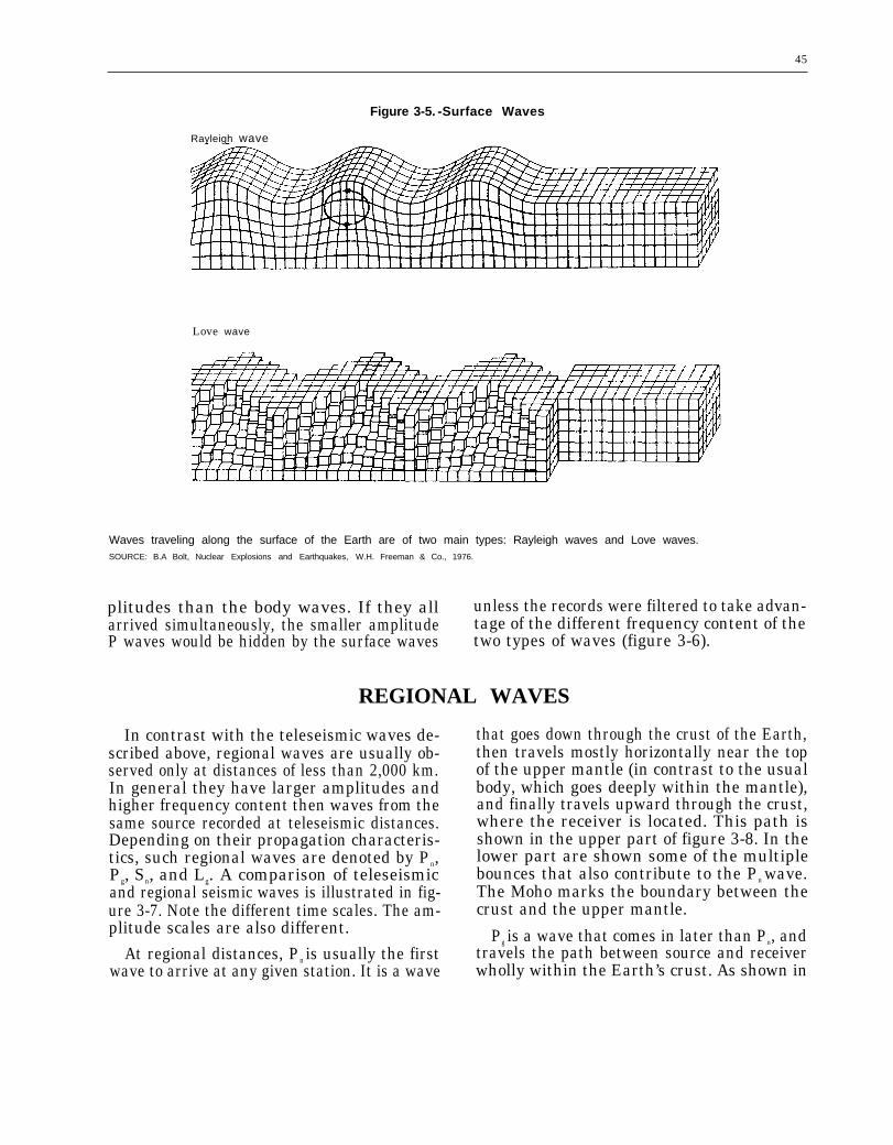
The particle motion of Rayleigh waves issomewhat analogous to that of ripples spread-ing over the surface of a lake. The analogy isnot exact, however, because unlike a waterwave, the orbital motion of a particle in a Ray-
‘These waves are named after the mathematicians who firstdeveloped the theory to describe their motion (Lord Rayleighand A.E.H. Love).
Figure 3-4.– Reflected and Refracted Waves
ReflectedI n c i d e n t ss
Reflected
Medium 1
M e d i u m 2
Refracted S
When a wave hits a boundary within the Earth both reflectedand refracted waves can be generated.
leigh wave is retrograde to the path of wavepropagation (figure 3-5a). The energy of theRayleigh wave is trapped near the ground sur-face, so as depth increases, the rock particledisplacements decrease until, ultimately, nomotion occurs.
The second type of surface wave whichtravels around the Earth is called a Love wave.Love waves have a horizontal motion that isshear, or transverse, to the direction of propa-gation (figure 3-5b). It is built up of trappedSH waves and has no vertical motion.
While Rayleigh waves can be detected byseismometers sensitive either to vertical orhorizontal motion of the Earth’s surface, Lovewaves are only detected by seismometers sens-ing horizontal motions.
Surface waves of either type, with a periodof 10 seconds, travel with a velocity of about3 kilometers per second. This corresponds toa wavelength of about 60 kilometers. Becauseof this long wavelength, surface waves aremuch less likely to be affected by small-scalevariations in Earth structure than short periodbody waves. This makes the use of surfacewaves attractive for measuring yields of So-viet tests. Body waves (P waves and S waves)are faster than surface waves and therefore ar-rive first at a recording station. This is fortu-nate because the surface waves have larger am-
45
Figure 3-5. -Surface Waves
Rayleigh wave
Love wave
Waves traveling along the surface of the Earth are of two main types: Rayleigh waves and Love waves.SOURCE: B.A Bolt, Nuclear Explosions and Earthquakes, W.H. Freeman & Co., 1976.
plitudes than the body waves. If they all unless the records were filtered to take advan-arrived simultaneously, the smaller amplitude tage of the different frequency content of theP waves would be hidden by the surface waves two types of waves (figure 3-6).
REGIONAL WAVES
In contrast with the teleseismic waves de-scribed above, regional waves are usually ob-served only at distances of less than 2,000 km.In general they have larger amplitudes andhigher frequency content then waves from thesame source recorded at teleseismic distances.Depending on their propagation characteris-tics, such regional waves are denoted by Pn,Pg, Sn, and Lg. A comparison of teleseismicand regional seismic waves is illustrated in fig-ure 3-7. Note the different time scales. The am-plitude scales are also different.
At regional distances, Pn is usually the firstwave to arrive at any given station. It is a wave
that goes down through the crust of the Earth,then travels mostly horizontally near the topof the upper mantle (in contrast to the usualbody, which goes deeply within the mantle),and finally travels upward through the crust,where the receiver is located. This path isshown in the upper part of figure 3-8. In thelower part are shown some of the multiplebounces that also contribute to the Pn wave.The Moho marks the boundary between thecrust and the upper mantle.
Pg is a wave that comes in later than Pn, andtravels the path between source and receiverwholly within the Earth’s crust. As shown in

46
Figure 3-6.—Seismograph Recording of P, S, and Surface Waves From a Distant Earthquake
P S u r f a c es w a v e s
A
Horizontal ground motion
SOURCE: Modified from F. Press and R. Seiver, Earth, W.H. Freeman & Co., San Francisco, 1974.
figure 3-9, Pg is thought to be guided by aboundary layer within the crust. It does notpropagate to as great a distance as Pn.
Sn is a shear wave that travels a path verysimilar to that of Pn, but arrives later. Sn ar-rives later because it is composed of shearwaves, which propagate slower than the Pwaves that make up Pn.
For purposes of explosion monitoring, Lcan be the most important of the regionalwaves because it is typically the largest waveobserved on a seismogram at regional dis-tances. Lg is a type of guided shear wave thathas most of its energy trapped in the Earth’scrust. In fact, this wave can be so strong that(contrary to what is implied by its inclusionin the class of “regional waves”) L for a large
explosion can be observed even at teleseismicdistances, i.e. well in excess of 2,000 km. The
observation of Lg out to teleseismic distances,however, can only occur across continents. Be-neath an ocean, where the crust is much thin-ner, Lg fails to propagate even short dis-tances.
Figure 3-10 illustrates how the Lg wavepropagates. At the top is shown a seismicsource within the Earth’s crust. Energy de-parting downward is partially reflected in thecrust and partially transmitted down into themantle. However, for waves that travel in themore horizontal direction, as shown in the mid-dle part of the figure, energy cannot get intothe mantle and is wholly reflected back intothe crust. The type of reflection occurring hereis the total internal reflection that is similarto that occurring within the prisms of a pairof binoculars. For a fixed source and receiver,there may be many reflection paths, all totally

47
Figure 3-7.—Regional and Teleseismic Signals
Regional signalP n P g
S n
1 1 Io 50 100
Time (seconds)
I Io 200 400
Time (seconds)
Upper seismogram is of a “regional distance” from the source. Signals here are associated with waves that propagate in thecrust and upper most mantle. Lower seismogram is of a “teleseismic distance. ” This wave has propagated through the deepinterior of the Earth.SOURCE” Modified from Defense Advanced Research Projects Agency.
Figure 3-8.—Pn Wave Figure 3-10.—Lg Wave
Source ReceiverSource Crust
(slow; low attenuation)Moho
\
Pn - wave
Figure 3-9.-Pg Wave
Source Receiver
Lower crustMoho
Mantle(faster; higher attenuation)
Total reflection
Wave guide. Many “trapped” rays in continental
Receiver
All totally reflected
Lg - wave
crust.
Moho
Pg - wave

48
reflected and thus trapped within the crust.This is illustrated in the bottom of the figure.The Lg wave is composed of the entire familyof trapped waves, with the crest acting as awave guide. For regions in which the crust iscomposed of material that transmits seismicwaves efficiently, Lg may be recorded at dis-tances of thousands of kilometers.
For most of the last 30 years, regional waveshave been thought of mainly in the context ofmonitoring small explosions which may not bedetected teleseismically. In recent years, how-ever, Lg has come to be recognized as usefulfor estimating yields for large explosions, in-dependent of the more conventional body waveand surface wave measurements (see ch. 7).
RECORDING SEISMIC WAVES
Seismic waves are measured at observato-ries around the world by recording the groundmotion. Most observatories have “triaxial”seismometers, meaning that they recordground motion in three directions at right an-gles to each other. Typically they are orientednorth-south, east-west, and vertical. By hav-ing all three components, seismologists canreconstruct the complete three-dimensionalground motion from the seismograms.
The principle by which the seismometerswork can bethought of as a heavy mass freelysupported by a spring from a frame fixed tothe Earth. When an earthquake or explosionoccurs, seismic waves traveling through theEarth reach the seismometer. The frame isshaken in response to the motion of the wave.Although the frame is displaced by the groundmotion, the heavy mass tends to remain sta-tionary because of its inertia. The displacementof the grounded frame relative to the station-ary mass is therefore a measure of the groundmotion. This movement is then electronicallymagnified so that displacements as small as0.00000001 centimeters (the same order asatomic spacings) can be detected.
If the Earth were perfectly still, recordingsmall earthquakes and underground explo-sions would be easy. However, processes suchas the winds, ocean waves, tides, man’s activ-ity, and seismic waves generated by earth-quakes in other regions continually cause mo-tions of the Earth. All of this motion is sensed
by seismometers and recorded. Although seis-mic instruments are sensitive enough to de-tect seismic waves generated by even thesmallest explosion, it will be seen in the fol-lowing chapters that naturally occurring back-ground noise levels are the limiting factor indetecting small earthquakes and explosions.
To reduce the background noise caused bywind and other surface effects, seismometershave been designed to fit into torpedo-shapedcasings and placed in narrow boreholes at adepth of about 100 meters. These types of sta-tions are currently being used as part of theRegional Seismic Test Network (RSTN). TheRSTN is a prototype system designed to evalu-ate the utility of in-country stations that couldbe placed within the Soviet Union to monitora low-yield or comprehensive test ban treaty.A typical high quality installation containsthree primary seismometers mounted in mutu-ally perpendicular orientations along withthree back-up seismometers (figure 3-11).
The seismometer installation is protectedagainst tampering both electronically andthrough the inherent ability of the instrumentto sense disturbances in the ground. The bore-hole package sends data to a surface stationthat contains transmitting and receivingequipment and in some cases to an antennafor satellite communications. Also containedin surface stations that might be used for mon-itoring are power sources, environmental con-

49
Figure 3-11 .—Seismic Instrumentation
Photo credits: Sandia National Laboratories
Seismic station downhole package containingseismometers, authentication circuits, and
processing electronics
Three seismometers mountedin mutually perpendicular
orientations
Seismometer

50
Photo credit: Sand/a National Laboratories
An example of what an internal seismic stationmight look like.
trol apparatus, and tamper-protection equip-ment. The distribution of six of these stationsin North America is designed to simulate thedistribution of 10 internal stations within theSoviet Union (figure 3-12).
Figure 3-12.— Distribution of RSTN Stations
Six Regional Seismic Test Network (RSTN) stations are dis-tributed throughout North American to simulate the distri-bution of 10 internal stations within the Soviet Union.
SOURCE: Modified from Sandia National Laboratories.
SEISMIC ARRAYSThe use of seismic arrays has been proposed
as an alternative and/or supplement to singlethree-component seismic stations. A seismicarray is a cluster of seismometers distributedover a fairly small area, usually on the orderof a few kilometers. The signals from the vari-ous instruments are then combined to improvethe detection and identification of any smallor weak signals that maybe recorded. Seismicarrays can function like phased array radarreceivers, sensitive to waves from a particu-lar direction while excluding waves from otherdirections. By doing so, arrays can pull smallsignals out from the surrounding backgroundnoise.
Figure 3-13.—Beamforming
To test the application of arrays for moni-toring regional seismic events, the UnitedStates and Norway installed the NorwegianRegional Seismic Array (NORESS) in 1984.NORESS is located north of Oslo and consistsof 25 individual sensors arranged in 4 concen-tric rings with a maximum diameter of 3 km.
Beamforming is a process of shifting and adding recordedwaveforms to emphasize signals and reduce noise. The origi-nal waveforms (a) can be shifted to remove propagation de-lays (b). The signal waveforms are now aligned but the noiseis not. The average of the shifted waveforms in (b) would bethe beam.
SOURCE: Energy & Technology Review, Lawrence Livermore National Labora-tory, August 1986, p. 13.

51
To imagine how an array works, consider anexample where a seismic wave is coming froma known location and with a known speed. Thetime it takes for the wave to travel to each sen-sor in the array can be predicted from theknown direction and speed. In contrast, theseismic background noise will vary randomlyfrom sensor to sensor. The recorded signalsfrom each sensor in the array can then beshifted in time to allow for propagation acrossthe array and combined (figure 3-13). The sen-sors are close enough so that the signal fromthe coherent source is nearly the same fromeach seismometer and remains unchanged. Thebackground noise varies more rapidly and can-cels out when the records are added together.Thus, it is possible to suppress the noise rela-tive to the signal and make the signal easier
to detect. This process of shifting and addingthe recorded waveforms is called beamform-ing. The combination of the shifted waveformsis called the beam.
Arrays do, however, have some drawbackscompared to three-component single stations:
1.
2.3.
A
they are more expensive because they re-quire more hardware and higher instal-lation costs;they require access to a larger area; andthey have more sensors that, in turn, gen-erate more data that must be trans-mitted, stored and processed.
comparison of the advantages and dis-advantages of arrays versus three-componentsingle stations is presented in chapter 4.