Embed Size (px)
Citation preview

123
Chapter 3
The Planetary Flybys
William A. Imbriale
The next era in Solar System exploration included flybys of the planets
with spacecraft carrying scientific instruments designed to study the
characteristics of the planets and intervening space. The Mariner series of
spacecraft was designed to study the inner Solar System, and the two Voyager
spacecraft were targeted for the outer planets.
Between 1962 and late 1973, The National Aeronautics and Space
Administration’s (NASA’s) Jet Propulsion Laboratory (JPL) designed and built
10 spacecraft named Mariner to explore the inner Solar System [1]—visiting
the planets Venus, Mars, and Mercury for the first time, and returning to Venus
and Mars for additional close observations. The next-to-last mission, Mariner 9,
became the first spacecraft to orbit another planet when it reached Mars for
about a year of mapping and measurement. The final mission in the series,
Mariner 10, flew past Venus before going on to encounter Mercury, after which
it returned to Mercury for a total of three flybys.
The Mariners were all relatively small robotic explorers, each launched on
an Atlas rocket with either an Agena or Centaur upper-stage booster, and each
weighed less than half a ton (without onboard rocket propellant). Each of their
missions was completed within a few months to a year or two, though one of
them outlived its original mission and continued to send useful scientific data
for three years.
The Voyager mission [2] was designed to take advantage of a rare
geometric arrangement of the outer planets in the late 1970s and the 1980s.
This layout of Jupiter, Saturn, Uranus, and Neptune (which occurs about every
175 years) allows a spacecraft on a particular flight path to swing from one
124 Chapter 3
planet to the next without the need for large onboard propulsion systems. The
flyby of each planet bends the spacecraft’s flight path and increases its velocity
enough to deliver it to the next destination. Using this “gravity assist”
technique, the flight time to Neptune, with the rockets available at that time,
was reduced from 30 years to 12. This mission has become known as The
Grand Tour.
3.1 The Mariner Series
The Mariner series of missions were designed to be the first U.S. spacecraft
to other planets, specifically Venus and Mars. This chapter focuses on the
Venus and Mercury flybys, and Chapter 4 describes the Mars missions.
3.1.1 Mariners 1 and 2
Mariners 1 and 2 (Fig. 3-1) were nearly identical spacecraft developed to
fly by Venus. The rocket carrying Mariner 1 went off-course during launch on
July 22, 1962, and was blown up by a range safety officer about 5 minutes into
flight. A month later, Mariner 2 was launched successfully on August 27, 1962,
sending it on a 3-1/2-month flight to Venus. On the way, it measured for the
first time the solar wind, a constant stream of charged particles flowing outward
from the Sun. It also measured interplanetary dust, which was found to be
scarcer than predicted. In addition, Mariner 2 detected high-energy charged
particles coming from the Sun, including several brief solar flares, as well as
cosmic rays from outside the Solar System. As it flew by Venus on December
14, 1962, Mariner 2 scanned the planet with infrared and microwave
radiometers, revealing that Venus has cool clouds and an extremely hot surface.
Because the bright, opaque clouds hide the planet’s surface, Mariner 2 was not
outfitted with a camera.
3.1.1.1 Mariner Antennas. The radio frequency (RF) subsystem [3,4]
employed four antennas for the various in-flight communications require-
ments. Reception of ground-transmitted signals was through the Command
Antenna System; a dipole antenna and a turnstile antenna mounted above and
below the outboard end of a solar panel. Both antennas relayed the received
890-MHz energy to the communications transponder through a flexible coaxial
cable.
Prior to spacecraft midcourse maneuver, an omnidirectional antenna
located at the apex of the spacecraft structure transmitted 960-MHz signals to
the ground. A separate L-band cavity amplifier provided power to the antenna.
Following midcourse maneuver and after the attitude of the spacecraft had been
corrected, the radio frequency (RF) power was radiated by a high-gain directive
antenna located at the base of the spacecraft hex structure. A separate cavity
amplifier also drove this antenna. The high-gain antenna (HGA) was nested at

The Planetary Flybys (Excluding Mars) 125
the base of the spacecraft structure until midcourse maneuver, when it swung
into position and faced the Earth. RF power was fed from the cavity amplifier
to the HGA through flexible coaxial cables and a rotary joint. The cavity
amplifiers were switched to provide either an omnidirectional pattern or an
Earth-directed lobe.
A substantial portion of the antenna system was inherited from the Ranger
Spacecraft. The omni antenna, for early flight telemetry, was the Ranger disc-
cone antenna. The directional HGA used the Ranger 1 feed modified for
circular polarization and a Ranger type parabolic reflector. This feed was then
also used on Rangers 6 and 7. Radio-frequency continuity between the HGA
Fig. 3-1. Mariner 2 spacecraft.
Roll Axis
RadiometerReferenceHorns
MicrowaveRadiometer
InfraredRadiometer
Omniantenna
MagnetometerSensor
Particle FluxDetectors(Geiger Tubes)
Ion-Chamber
Cosmic DustDetector
Hex Cases
Earth Sensor
Solar Panel
CommandAntenna
Attitude ControlGas Bottles
Solar PlasmaDetector
Solar Sail
Directional Antenna

126 Chapter 3
and the communications system during relative motion of the antenna and bus
was provided by a Ranger 1-type coaxial rotary joint and associated cabling.
Omni antenna. The omni antenna, having been taken directly from the
Ranger configuration, required no design work, but some structural
strengthening was necessary. The omnidirectional antenna was located at the
apex of the spacecraft structure and was driven by a separate L-band cavity
amplifier.
Command antenna subsystem. The command antenna subsystem
consisted of a turnstile antenna mounted on the backside of the solar panel and
a dipole antenna mounted on the forward side of the solar panel (Fig. 3-2). To
split the power between the two antennas, a directional coupler was used, with
the dipole being driven 6 dB below that of the turnstile.
High-gain antenna. Requirements for the Mariner HGA design were the
following:
1) The existing paraboloidal reflector had to be used with a minimum of
modifications.
2) The design had to provide an efficient circularly polarized feed at
960 MHz.
3) The feed structure had to be compatible with the adapter diaphragm of the
Ranger-Agena B vehicle.
A feed design was quickly accomplished by modifying the existing
Ranger 1 configuration. The modification involved the replacement of the
linearly polarized dipole elements with circularly polarized turnstile elements
consisting of two dipoles oriented 90 deg from each other and 45 deg from the
balun slot on the outer conductor. In the design, circular polarization was
achieved by the phase quadrature of the essentially equal currents flowing in
the crossed dipoles when one dipole was cut appropriately shorter than that
required for resonance and the other appropriately longer than that required for
resonance.
Several focal-length positions were examined in order to optimize the gain.
At each position, the element lengths were adjusted to produce nearly circular
polarization, meeting the criterion that the gain variation versus incident linear
polarization angle be less than 0.2 dB. The 1-dB and 3-dB beamwidths of the
antenna were 10.3 and 16.5 deg, respectively. Absolute gain relative to right-
hand circular polarization (RHCP) of the antenna was measured to be
20.0 ±0.5 dB. Gain variation of the antenna versus incident linear polarization
angle (ellipticity) was measured to be 0.33 dB.
3.1.2 Mariner 5
The Mariner 5 spacecraft was originally built as a backup to Mariner 4, a
Mars craft launched in 1964. When Mariner 4 completed its mission

The Planetary Flybys (Excluding Mars) 127
successfully, the backup was rechristened Mariner 5 and reoutfitted for a flyby
of Venus. Launched from Cape Canaveral, Florida, in June 1967, Mariner 5
(Fig. 3-3) flew within about 4,000 km (approximately 2,500 miles) of Venus
some four months later. Mariner 5’s flight path following its Venus encounter
brought it closer to the Sun than any previous probe.
Fig. 3-2. Mariner 2 command antennas: (a) dipole and (b) turnstile.
(a)
(b)

128 Chapter 3
The spacecraft antenna subsystem included a low-gain antenna (LGA), an
HGA, and their transmission lines [5]. The function of the LGA was to receive
commands from Earth and to transmit telemetry to Earth during the first half of
the mission and during midcourse maneuver. The primary function of the HGA
was to transmit telemetry to Earth during the last half of the transfer orbit and
for a period after planetary encounter. The Earth-look angles were somewhat
different than those for the Mariner 4 mission. Look angles for Venus
continued away from the low-gain peak after encounter, while those at Mars
reversed and retraced through the low-gain beam. Thus, the trajectories put the
Earth-look angles on the opposite sides of the spacecraft. This placement of
these angles would not have been a difficult problem if only telemetry and
command requirements had to be met, since the encounter range of Venus was
only 80 million km, whereas it was 222 million km for Mars in 1965. Hence,
for the Venus encounter, the antenna gain required was about 9 dB less than
that for Mariner 4 at Mars. If this antenna gain, then, was the only requirement,
a relatively small antenna could have been packaged on the opposite side of the
Mariner 4 type-spacecraft to accomplish the encounter antenna coverage.
However, the S-band occultation experiment had to be considered as a key
element, and for this, a nominal peak gain of 21.5 dB was required, which was
approximately the gain required for telemetry return from Mars by Mariner 4.
Fig. 3-3. Mariner 5 spacecraft.

The Planetary Flybys (Excluding Mars) 129
This fact sized the Mariner 5 HGA to something approximately the same as the
Mariner 4 HGA.
Since an antenna of this size would be impossible to position between the
spacecraft and the Agena or between the bus and the shroud adapter, the
antenna would have had to be stowed above the bus during launch and
deployed after planetary injection, or the solar axis of the spacecraft would have
had to be reversed. Of these two choices, the reversal of the solar axis appeared
to be not only inherently the most reliable but also the easiest to implement.
In this configuration, the Mariner 4 LGA could be used without changes for
Mariner 5, since the cone angle variations of Earth with time from launch to
loss of LGA signal would now be similar. Clock-angle variations were not of
significance in the LGA selection, since its pattern was essentially symmetrical
about the roll axis.
Hence, S-band antennas made for Mariner 4 were used for Mariner 5 with
only minor changes. The LGA consisted of an RHCP mode launcher in the base
of a 2.1-m-long, 0.10-m-diameter circular aluminum waveguide, with a crossed
slot radiator and a ground-plane system at the other end (Fig. 3-4). The base of
the antenna was mounted in a fixed position on the spacecraft structure with the
waveguide extending parallel to the spacecraft Z-axis.
Fig. 3-4. Mariner 5 low-gain antenna.

130 Chapter 3
The HGA consisted of a reflector and feed (Fig. 3-5). The reflector was a
sectoral paraboloid, with an elliptic aperture that had a major axis of 1.17 m and
a minor axis of 0.53 m. The feed was an array of two turnstile elements driven
in phase through a stripline power divider and matching network. The HGA
was right-hand circularly polarized. A fiberglass feed support truss joined the
feed and reflector, an antenna support truss joined the reflector to the
spacecraft, and a section of rigid coax tubing (supported by the feed and
antenna support trusses) passed from the feed through the reflector.
Fig. 3-5. Mariner 5 breadboard high-gain antenna.

The Planetary Flybys (Excluding Mars) 131
Unlike Mariner 4, the Mariner 5 HGA had two separate positions to
accommodate the occultation experiment. For a fixed on-board antenna, the
occultation experiment required two peaks with approximately 21.5 dB nominal
gain, each spaced 53 deg apart in the plane containing the earth track with
sufficient cross Earth track to account for out-of-plane bending of the
occultation whiskers. Various antenna studies narrowed the logical choice to
the Mariner 4 HGA with its 23.2-dB peak gain and 2.06:1 beamwidth aspect
ratio, along with a simple one-step position change to be made while the
spacecraft was behind the planet. This choice would allow optimum pointing of
the antenna back along the Earth track when entering occultation, then, allow it
to be placed to a second position behind the planet allowing optimum pointing
for the outgoing occultation. The offset angle chosen for the first position of the
HGA was a compromise between occultation optimization and telemetry return
to Earth after encounter in the event that the antenna pointing angle change did
not occur. Hence, the first offset angle was –8.2 deg, while the exit occultation
offset was 9.5 deg.
Changes made to accommodate the two positions included the addition of
a new mounting interface structure and revision of the coaxial cabling between
the antenna and the electronic cases. A tuned mismatch was inserted in the
LGA transmission line as a result of an interferometer problem on Mariner 4
caused by insufficient isolation between the high-gain and low-gain antennas.
A detailed discussion of this problem may be found in [5].
3.1.3 Mariner 10
With Mariner 10, JPL engineers embarked on an experiment with an
ingenious way of traveling through the Solar System using the gravity of one
planet to help propel the craft on to the next destination—somewhat like a
series of bank shots in a game of billiards [6].
With the scorched inner planet Mercury as its ultimate target, the final
Mariner pioneered the use of a “gravity assist” swing by the planet Venus to
bend its flight path. Using a near-ultraviolet filter, it produced the first clear
pictures of the Venusian chevron clouds and performed other atmospheric
studies before moving to the small, airless, cratered globe of Mercury. Here a
fortuitous gravity assist enabled the spacecraft to return at six-month intervals
for close mapping passes over the planet, covering half the globe (Mercury’s
slow rotation left the other half always in the dark when Mariner 10 returned).
The S/X-band antenna subsystem requirements provided for transmission
and reception of S-band signals between the DSN and the Mariner spacecraft
and for transmission of X-band signals from the spacecraft to the DSN [7,8].
The subsystem consisted of one HGA, one LGA, an HGA coupler, plus the
necessary RF transmission lines and associated connectors. The HGA
requirements were to downlink S-band (2295 + 5 MHz) and X-band (8415 + 20

132 Chapter 3
MHz) using an RHCP signal. The gain requirements were S-band
27.6 ±0.25 dB and X-band 38.2 ±0.4 dB. The LGA requirements were to uplink
and downlink S-band (2115 ±5 MHz receive and 2295 ±5 MHz transmit). The
polarization was RHCP, and the minimum gains at mercury encounter when the
Sun was acquired were receive –4.1 dB and transmit –3.1 dB.
A schematic of the antenna subsystem is shown in Fig. 3-6. The HGA was
a steerable parabolic dish 54 in. (137.2 cm) in diameter with a focal length of
21.6 in. (54.88 cm). It used a collocated S-and X-band focal point feed where
the S-band feed was an annular cavity, and the X-band feed was an open-ended
circular waveguide. The LGA was a boom-mounted biconical antenna with the
boom used as an air-dielectric coaxial transmission line. It was fixed mounted
after deployment from stowed position, but it had a post-Mercury encounter
redeployment capability. The transmission lines used 50- semi-rigid coax, and
the deployment and articulating joints used 50- flexible coax.
There was some heritage from the earlier Mariner missions for the HGA
dish materials, but the feed was new, and the LGA was a new design patterned
after a lunar orbiter LGA design but with simplified feed and thermal expansion
joint. The antenna subsystem weight was 7.24 lb (3.3 kg).
Pictures of the HGA feed are shown in Figs. 3-7 and 3-8. Studies were
made of the vertex-to-feed distance, and the outer cup depth and the measured
data for S-band are shown in Fig. 3-9. The selected design was 22.2 in.
(56.4 cm) focal distance and 1.6 in. (4.1 cm) cup. The measured gains were
27.6 dB at S-band and 38.74 dB at X-band.
The Mariner LGA configuration is shown in Fig. 3-10. Typical patterns
compared to the specification are shown in Fig. 3-11.
3.2 Voyager Mission to the Outer Planets
The Voyager mission [2] was designed to take advantage of a rare
geometric arrangement of the outer planets in the late 1970s and the 1980s.
This layout of Jupiter, Saturn, Uranus, and Neptune, which occurs about every
175 years, allows a spacecraft on a particular flight path to swing from one
planet to the next without the need for large onboard propulsion systems. The
flyby of each planet bends the spacecraft’s flight path and increases its velocity
enough to deliver it to the next destination. Using this “gravity assist”
technique, the flight time to Neptune was reduced from 30 years to 12.
While the four-planet mission was known to be possible, it was deemed to
be too expensive to build a spacecraft that could go the distance, carry the
instruments needed, and last long enough to accomplish such a long mission.
Thus, the Voyagers were funded to conduct intensive flyby studies of Jupiter
and Saturn only. More than 10,000 trajectories were studied before choosing
the two that would allow close flybys of Jupiter and its large moon Io, and

The Planetary Flybys (Excluding Mars) 133
Fig. 3-6. Mariner 10 antenna subsystem (CT = coil terminal).
LGA Feed
Flexible CoaxAcross DeploymentJoint
0.5-in. (1.27-cm)SpirolineSemi-Rigid Coax
Flexible Coax atDeployment andArticulation Joint
4 CT Connectorsat All Coax CableJoints in the SXA Subsystem
X-Band Feed
S-Band Feed
S-Band Hybrid Coupler
54-in. (137-cm) Reflector andFeed Support StructureNot Part of SXA Subsystem
4 Count Connectorto RG-142 Cable
Antenna Boom(Structures)
Biconical Radiator(Structures)
0.5-in. (1.27-cm) SpirolineSemi-Rigid Coax

134 Chapter 3
Saturn and its large moon Titan. The chosen flight path for Voyager 2 also
preserved the option to continue on to Uranus and Neptune.
From the NASA Kennedy Space Center at Cape Canaveral, Florida,
Voyager 2 was launched first, on August 20, 1977; Voyager 1 was launched on
a faster, shorter trajectory on September 5, 1977. Both spacecraft were
delivered to space aboard Titan-Centaur expendable rockets. The prime
Voyager mission to Jupiter and Saturn brought Voyager 1 to Jupiter in 1979
and Saturn in 1980, while Voyager 2 flew by Jupiter in 1979 and Saturn in
1981. Voyager 1’s trajectory, designed to send the spacecraft closely past the
large moon Titan and behind Saturn’s rings, bent the spacecraft’s path
inexorably northward out of the ecliptic plane—the plane in which most of the
planets orbit the Sun. Voyager 2 was aimed to fly by Saturn at a point that
would automatically send the spacecraft in the direction of Uranus.
After Voyager 2’s successful Saturn encounter, it was shown that
Voyager 2 would likely be able to fly on to Uranus with all instruments
operating. NASA provided additional funding to continue operating the two
spacecraft and authorized JPL to conduct a Uranus flyby. Subsequently, NASA
also authorized the Neptune leg of the mission, which was renamed the
Fig. 3-7. Mariner 10 HGA feed.

The Planetary Flybys (Excluding Mars) 135
Voyager Neptune Interstellar Mission. It should be pointed out, however, that
although Voyager 2 was targeted to fly by Uranus and Neptune, the
telecommunications link was only designed for operation at Jupiter and Saturn.
Since it was not possible to change the spacecraft, significant improvements in
the ground portion of the link were necessary for a successful mission at
Uranus and Neptune. A description of the many improvements to the ground
antenna system can be found in [9]. It included, among other things, an addition
of another 34-m antenna subnet, increasing the size of the existing 64-m
antennas to 70-m, and arraying 34-m and 70-m antennas.
Voyager 2 encountered Uranus on January 24, 1986, returning detailed
photos and other data on the planet, its moons, its magnetic field, and its dark
rings. Voyager 1, meanwhile, continued pressing outward, conducting studies
of interplanetary space. Eventually, its instruments may be the first of any
spacecraft to sense the heliopause—the boundary between the end of the Sun’s
magnetic influence and the beginning of interstellar space.
Following Voyager 2’s closest approach to Neptune on August 25, 1989,
the spacecraft flew southward, below the ecliptic plane and onto a course taking
it, too, to interstellar space. Reflecting the Voyagers’ new transplanetary
destinations, the project name was changed to the Voyager Interstellar Mission.
Fig. 3-8. Mariner 10 HGA feed, exploded view.
Single Strap and Shorting RingNot Used in Flight Units

136 Chapter 3
Ante
nna G
ain
(dB
)
28
27
26
21.0[53.3]
22.0[55.9]
Outer Cup = 1.60 in. (4.06 cm)
(a)
(b)
Vertex to Feed Distance (in.) [cm]
Outer Cup Depth (in.) [cm]
Ante
nna G
ain
(dB
)
28
27
26
1.50[3.75]
1.70[4.32]
1.60[4.06]
F = 22.2 in.(55.9 cm)
Fig. 3-9. Mariner 10 HGA S-band gain measurements (measurements obtained using linear standard gain horn): (a) vertex to feed distance and (b) outer cup depth.

The Planetary Flybys (Excluding Mars) 137
Voyager 1 is now leaving the Solar System, rising above the ecliptic plane
at an angle of about 35 degrees at a rate of about 520 million kilometers (about
320 million miles) a year. Voyager 2 is also headed out of the Solar System,
diving below the ecliptic plane at an angle of about 48 degrees and a rate of
about 470 million kilometers (about 290 million miles) a year.
Both spacecraft will continue to study ultraviolet sources among the stars,
and the fields and particles instruments aboard the Voyagers will continue to
search for the boundary between the Sun’s influence and interstellar space. The
Voyagers are expected to return valuable data for two or three more decades.
Communications will be maintained until the Voyagers’ nuclear power sources
can no longer supply enough electrical energy to power critical subsystems.
3.2.1 Voyager S-/X-Band Antenna Subsystem
The Voyager spacecraft (Fig. 3-12) S-/X-band antenna subsystem (SXA) is
required to (1) receive S-band signals from the DSN and conduct them to the
radio frequency subsystem (RFS), (2) transmit S-band signals from the RFS to
the DSN, and (3) transmit X-band signals from either RFS X-band traveling
wave tube assembly (TWTA) to the DSN [10,11].
A schematic diagram of the SXA is shown in Fig. 3-13. It consists of an
HGA, an LGA, transmission lines (including waveguide and X-band power
monitors), and RF power probes located on the HGA main reflector and the
LGA cavity.
Fig. 3-10. Mariner 10 LGA configuration.
Base Short
RF Feed
TeflonSpacers(4 Pair)
TeflonTape
Expansion Joint Matching Section

138 Chapter 3
3.2.2 Requirements
The HGA consists of a paraboloidal reflector with a 3.66-m (12-ft.)
diameter circular aperture and suitable S- and X-band feeds. The X-band feed
utilizes dual shaped Cassegrain optics, and the S-band feed utilizes a prime
focus feed. A frequency selective subreflector (FSS) reflects the X-band signal
and passes the S-band signal. The HGA has a focal length to diameter (F/D)
ratio of 0.338. The HGA is RHCP and operates over the frequency ranges of
Dire
ctivity (
dB
)
0
–10
–200 90 180
(a)
Cone Angle (deg)
Pattern Minimum
Requirement(Included 0.5-dBUncertainty)
Mariner 10 LGA Pattern Coverage2115-MHz Solar Panel at 60 deg
IsotropicLevel
Pattern Peak
Fig. 3-11. Mariner 10 LGA patterns: (a) 2115 MHz and (b) 2295 MHz.
Dire
ctivity (
dB
)
0
–10
–200 90
69
69 180
(b)
Cone Angle (deg)
Pattern Minimum
Requirement(Included 0.5-dBUncertainty)
Mariner 10 LGA Pattern Coverage2295-MHz Solar Panel at 0 deg
IsotropicLevel
Pattern Peak

The Planetary Flybys (Excluding Mars) 139
2115 ±5 and 2295 ±5 MHz. It also operates over the frequency range of 8422
±20 MHz, with a dual polarized feed that yields a right-hand or left-hand
circularly polarized wave from the HGA depending on which of its input ports
is excited by the RFS. S-band signals are received by the HGA at 2115 ±5 MHz
and routed to the RFS receiver. S-band signals at 2295 ±5 MHz from the RFS
Fig. 3-12. The Voyager spacecraft.
Fig. 3-13. Voyager SXA subsystem.
LGA Pick-Up Probe
LGA
S-Band HGA FeedFSS
HGA Feed Cable
LGA Feed Cable
LGA Pick-Up Probe Cable
X-Band Feed
HGA Pick-Up Probe
Primary Reflector
Waveguidesto RFS
Cables to RFS
ProbeProbe
140 Chapter 3
S-band transmitter are radiated via the HGA. X-band signals at 8422 ±20 MHz
from the RFS X-band transmitter are radiated via the HGA.
The LGA radiates a circularly polarized, broadbeam pattern directly to
Earth. The LGA requirements are summarized in Table 3-1.
3.2.3 Voyager High-Gain Antenna
Since a 3.66-m reflector was the largest solid reflector diameter that could
fit into the nose cone fairing without deployment, it was desirable to have the
highest aperture efficiency possible. A high-efficiency dual-reflector system
generally requires that (1) most of the feed energy be intercepted by the reflec-
tors (i.e., low spillover), and (2) the field in the aperture of the main reflector be
distributed as uniformly as possible. Ordinarily, reduction of spillover requires
tapering the aperture distribution, and a uniform aperture distribution generally
involves substantial spillover. Consequently, optimum performance
traditionally involves a compromise that has limited efficiencies of
conventional systems to about 55–60 percent. The shaped dual-reflector
concept permits the apparent contradiction between the two requirements for
high efficiency to be overcome with the following rationale: a feed is selected
with a high taper at the edge of the subreflector to minimize forward spillover;
the subreflector profile is designed to distribute the highly tapered energy
uniformly over the aperture of the main reflector. By designing for constant
aperture illumination (see Section 1.2.4), the classical hyperboloid subreflector
is transformed into an empirical contour with a smaller radius of curvature than
a hyperboloid in the central section to deflect more of the rays to the outer part
of the main reflector. Thus, there is little spillover and, at the same time, a
nearly uniform aperture distribution. The main reflector must then be slightly
Table 3-1. Voyager low-gain antenna requirements.
Parameter Requirement
Frequency bands
Power handling
Polarization
Axial ratio
Boresight gain (at input connector) pattern
VSWR
2115 ±5 MHz (receive) 2295 ±5 MHz (transmit)
120 W continuous wave (CW)
RHCP
2115 MHz ≤6 dB For ±90-deg cone angle band ≤2 dB On boresight
2295 MHz ≤11 dB For ±90-deg cone angle band ≤2 dB On boresight
≥7.5 dBi for 2115-MHz band ≥7.6 dBi for 2295-MHz band
≤1.2 : 1 for both bands
{
{

The Planetary Flybys (Excluding Mars) 141
reshaped from its original paraboloidal contour to produce a constant-phase
distribution
The HGA was dual-shaped for optimum efficiency at X-band (see
Fig. 3-14). The dichroic subreflector is transparent to radiation from an S-band
prime-focus horn nestled behind it. At S-band, the main reflector differs little
from a paraboloid. The focus of the resultant best-fit paraboloid was chosen as
the prime focus for the S-band feed.
3.2.3.1 X-band Feed. The X-band feed [12] is required to illuminate the
subreflector with circularly symmetric, circularly polarized energy of a
prescribed pattern shape with constant pattern phase. A subreflector edge
illumination level of 17.5 dB below the boresight pattern level was chosen as
the best comprise between the –25 dB optimum gain edge illumination and
typical feed phase patterns, which have large rates of change past the –17.5 dB
points.
The subreflector shape was calculated based on a computer-predicted
pattern for the dual-mode horn baseline feed. Therefore, the computer-predicted
Fig. 3-14. Voyager HGA geometry.
Feed PhaseCenter
Focal Point
Focal Point of "Best Fit" Parabola = 48.671 in. (123.62 cm)
Focal Length of "Best Fit" Parabola = 48.626 in. (123.51 cm)
26.521 in.(67.36 cm)
23.2 deg
4.823 in.(12.25 cm)
44.500 in.(113.03 cm)
19.88 in.(50.50 cm)
72 in.(182.88 cm)
12.619 in.(32.05 cm)

142 Chapter 3
pattern was the design goal for the X-band breadboard feed. The X-band feed
requirements are summarized in Table 3-2.
3.2.3.2 Trade-off Studies. Circular polarization consists of two spatially
orthog-onal E-field components 90 deg out of time phase. Good circular
polarization for a given feed horn pattern can occur only if the pattern is closely
matched in orthogonal planes and has nearly identical phase-centers in
orthogonal planes. Radiation patterns in the dominant transverse electric (TE11)
circular waveguide mode have narrower E-planes than H-planes due to the
more nearly uniform E-field aperture distribution in the E-plane. Radiation in
the transverse magnetic (TM11) mode, in phase with the TE11 mode at the horn
aperture, increases E-plane beamwidth and reduces E-plane sidelobe levels
without affecting H-plane radiation patterns.
Potter [13] found that TM11 power in the proper ratio to the TE11 mode
could nearly equalize E- and H-plane beamwidths. Ludwig [14] found that
radiation from the TE12 and TM12 modes in combination with the TE11 mode
and TM11 mode could produce beams with fairly flat tops and steep skirts, or
shaped beams with nearly equal E-and H-plane beamwidths. The combination
of the TE11 and TM11 mode is the hybrid HE11 mode, and the combination of
TE12 mode and TM12 mode is the HE12 mode. An antenna radiating in the HE11
and HE12 modes is a dual hybrid-mode antenna.
Therefore, the X-band feed candidate antennas considered were the dual
mode horn, the corrugated horn, and the dual hybrid-mode horn. The operation
of each of these type horns is described in the following paragraphs.
3.2.3.2.1 Dual Mode Horn. TM11 mode power is generated at the step change
in circular waveguide size as a result of the boundary condition requiring
tangential E-fields to vanish at a perfectly conducting wall. The ratio of
waveguide diameter left of the step to the waveguide diameter to the right of
the step, or step ratio, determines the ratio of TM11 mode power to TE11 mode
power to the right of the step.
Table 3-2. Voyager X-band feed specifications.
Parameter Required Performance
Frequency band
Polarization
Power handling
VSWR
Axial ratio
8422 ±20 MHz
RHCP and LHCP from two different input ports
105 W CW
≤1.2 : 1.0
≤1.0 dB*
* Internal specification. The X-band system axial ratio specification
is 1.5 dB on the boresight axis.

The Planetary Flybys (Excluding Mars) 143
The waveguide size at the left of the step was chosen such that the TM11
mode is below cutoff. The TM11 mode and TE11 mode propagate with different
phase velocities, and therefore change their relative phase relationship in the
horn flare section.
The phasing section also yields a differential phase shift between the two
modes. Its length was adjusted during testing so that the two modes are in phase
at the aperture. For the Voyager antenna, the phasing section length was
determined experimentally because, although the differential phase shift
between the two modes in the flare section could be calculated, the computer
program did not calculate the initial phase relationship at the step. The depend-
ence on the absolute length of the phasing and flare sections for proper
performance limits the dual mode horn bandwidth to between 5 and 10 percent.
3.2.3.2.2 Corrugated Horn. The corrugated horn utilizes TE11 and TM11 mode
radiation to equalize E- and H-plane beamwidths. The bandwidth limitations of
the stepped dual mode horn are overcome by using corrugations to generate
TM11 mode power in a distributed manner along the flare section, thus
eliminating the phase difference between the two modes. The corrugations,
which are /4 deep, may be viewed as providing equal boundary conditions in
the E- and H-planes. There should be enough corrugations per wavelength such
that the corrugated wall performs as an anisotropic surface.
3.2.3.2.3 Dual Hybrid-Mode Horn. It is possible to add hybrid modes in a
corrugated waveguide analogously to adding individual TE and TM modes in a
smooth waveguide. The TM11, TE12, and TM12 modes are generated at the step
and propagate through the corrugated flare section, unlike in the dual-mode
horn that attenuates the HE12 mode in its phasing section. The combination of
the two hybrid modes can produce radiation patterns with nearly equal and
shaped E- and H-plane beams over a narrow band. JPL [15] has tested a dual-
hybrid-mode horn from 8.3 GHz to 8.6 GHz and has developed computer
analysis programs for the horn.
3.2.3.2.4 Choice of Dual-Mode Horn as X-Band Feed. The Voyager X-band
bandwidth is 0.475 percent, which is well within the 5-percent bandwidth
capability of the dual-mode horn; therefore, the wideband, corrugated horn
design offers no advantage over the dual-mode horn and is more expensive to
fabricate. Although the beam-shaping property of the dual-hybrid-mode horn
could yield some advantages over the dual-mode horn, the use of dual-shaped
optics for the reflector system negates that advantage. Also the increased
complexity, fabrication cost, weight, and blockage at S-band of the dual-
hybrid-mode horn over the dual-mode horn makes the dual-mode horn the clear
choice as the X-band feed.

144 Chapter 3
3.2.3.2.5 Detailed Design of the Voyager X-Band Feed Horn. Figure 3-15
gives the dimensions of the feed, the polarizer, and the orthomode transducer,
and the following describes the process used to determine the design. Some of
the parameters were determined empirically, as the computer programs used at
that time did not provide a complete solution. The program described in
Section 1.2.2 could be used today to completely design the horn without the
need for measurements.
Aperture diameter. The addition of the TM11 mode radiation pattern to the
TE11 mode pattern broadens the E-plane beam to match the H-plane beam,
without affecting the H-plane beam; therefore, the diameter of the dual-mode
horn was chosen based on the H-plane pattern of a dominant mode horn. A
4.905-in. (12.46-cm) diameter (~3.5 wavelengths) aperture yields a –17.5-dB
pattern taper at the 23.2-deg subreflector edge cone angle. A computer program
computed the radiation pattern for a TM11/TE11 mode voltage ratio of 10.626,
both modes in phase, and a 4.905-in. (12.46-cm) diameter aperture. This
computer pattern was then used as the design goal for the feed because the
subreflector shape was determined from the computer-predicted feed pattern.
Phasing section design. The phasing section diameter, 2.05 in. (5.21 cm),
was chosen to be 20 percent above the TM11 mode cutoff diameter at
8422 MHz. The closer the TM11 mode is to cutoff, the more effective is a given
length of phasing section in providing the required TE11 to TM11 mode
differential phase shift to put the two modes in phase at the aperture. However,
if the TM11 mode is too close to cutoff, its guide wavelength varies radically
with frequency, thus severely limiting the antenna bandwidth. A phasing
section diameter 20 percent above the TM11 mode cutoff diameter is a
Fig. 3-15. Voyager HGA X-band feed horn cross section and dimensions.
Phasing Section
26.488 in.(67.28 cm)
1.000 in.(2.54 cm)
Side Port(RHCP) Back
Port(LHCP)
0.475in.
(1.21 cm)
6.412 in.(16.29 cm)
Polarizer/OMT
Note: Polarizer Pins are Spaced0.486 in. (1.23 cm) Apart and Penetrate≅ 0.17 in. (0.43 cm) Into the Waveguide
Horn
11.416 in.(29.00 cm)
3.59 in.
(9.12 cm)
3.595 in.
(9.13 cm)
1.638 in.(4.16 cm) Diameter
1.08 in.(2.74 cm) Diameter
1.215 in. (3.09 cm) Diameter2.05 in. (5.21 cm) Diameter
Polarizer Tuning Screws
OMT Iris MatchingScrews
5.154 in.(13.09 cm)

The Planetary Flybys (Excluding Mars) 145
compromise between phasing section effectivity and antenna bandwidth. Also,
a small diameter phasing section is effective in attenuating modes of higher
order than TM11 generated at the step.
Step ratio. The E-plane pattern of the dual-mode horn is only an
approximation to the H-plane pattern. One design factor in a dual-mode horn is
the pattern level at which the E- and H-plane coincide. The feed breadboard
step ratio was chosen such that the –10 dB points coincide. Designing the step
so that the E- and H-plane beams coincide at the –10 dB pattern levels causes
the beams to be in close agreement for the 23.2-deg portion subtended by the
subreflector. Breadboard tests determined that a step ratio of 0.799 optimized
the beamwidth match.
Input matching section. A quarter-wave transformer and a linear taper
were each considered for matching the input or feed waveguide impedance to
the waveguide impedance at the step section input. The linear taper was not
used because it was 3 in. (7.62 cm) longer than the quarter-wave transformer
and more suited to wideband applications.
3.2.3.3 X-Band Performance Summary. The performance of the antenna
system at X-band is summarized in Table 3-3.
3.2.4 Voyager S-Band Feed and Low-Gain Antenna Design
The S-band feed and LGAs [16] are back-to-back in the SXA system
(Fig. 3-13). The S-band feed is required to illuminate the main reflector with
Table 3-3. Voyager X-band performance summary at 8422 ±20 MHz.
RF ParameterRHCP LHCP
SpecificationMeasured Performance
Gain (dB)
Efficiency (η) (percent)
Axial ratio (on-axis) (dB)
3-dB beamwidth (deg)
10-dB beamwidth (deg)
First sidelobe angle from boresight (deg)
First sidelobe level (dB)
8402 MHz VSWR 8422 MHz 8442 MHz
8402 MHz Isolation (dB) 8422 MHz 8442 MHz
≥48.3
64.9
≤1.5
≥0.5
≥0.9
≥0.9
>15.0
≤1.2 : 1
>20
47.96
60.0
0.6
0.58
0.97
0.9
13 to 17
1.06 : 1 1.03 : 1 1.03 : 1
47.98
60.2
0.6
0.58
0.97
0.9
13 to 17
1.17 : 1 1.05 : 1 1.06 : 1
20.519.518.6

146 Chapter 3
circularly polarized power in a circularly symmetric pattern with a prescribed
edge taper. The feed position is the focal point of the best-fit parabolic
approximation of the main reflector. The LGA radiates a circularly polarized,
broadbeam pattern directly to Earth. Fig. 3-16 is the LGA pattern specification.
Tables 3-4 and 3-5 summarize the LGA and S-band feed design requirements.
A calculated prime focus fed parabola efficiency curve versus reflector edge
illumination shows that the S-Band HGA efficiency will be nearly identical for
feed patterns rolling off from –8 dB through –11 dB with respect to boresight at
the 73-deg cone angle subtended by the main reflector. This wide range of feed
patterns for high efficiency performance of the HGA S-band system allowed
use of an antenna design that meets both the LGA patterns and S-band feed
specifications, thereby reducing system cost and complexity. The sense of
circular polarization is the only difference between the two antennas. Because
the S-band feed and the LGA are of the same design, they shall hereafter be
referred to as the S-band feed/LGA.
3.2.4.1 Design Summary. The initially proposed S-band feed and LGA was a
self-phased crossed dipole matched by a triple tuner. Concern about the thermal
stability and reliability of the triple-stub tuner resulted in a change of the
S-Band feed/LGA to a hybrid-fed crossed dipole (HFCD). The HFCD design,
Fig. 3-17, provides the four-way equal power split and 0, –90, –180, –270 deg
phase progression required for circular polarization from a 180-deg ring hybrid
feeding two 90-deg “over and under” couplers. The four outputs of the two
90-deg hybrids are connected to the four printed circuit radiating elements by
sections of 0.141-in. (0.36-cm) diameter semi-rigid cables. The cables run the
length of the square, beam-shaping cavity. An alternate approach to feeding the
four radiating elements would have been to use a single 90-deg hybrid feeding
the two orthogonal pairs of radiating elements; the opposite elements dividing
current using a quarter-wave balun.
The balun design, however, required close feed-cable spacing and a cross
strap between opposite radiating element pairs; both susceptible to voltage
breakdown. The radiating cavity dimensions are such that the S-band feed
pattern at 73 deg illuminates the main reflector edge at –11 dB. This edge
illumination is in the maximum efficiency region for the primary reflector.
The breadboard LGA design is an S-band feed element with two 1/2-in.
(1.27-cm) spaced, 6-in. (15.24-cm) diameter conductive disks conforming to
the radiating cavity wall and with the upper disk at the level of the radiating
element. The upper disk forms a ground plane that narrows the pattern half-
power beamwidth from ~94 deg to ~77 deg and increases the gain from
~6.3 dBi to ~8.0 dBi, so that the LGA gain specification can be met. The lower
disk, upper disk, and cavity wall roughly form a quarter-wave, short-circuited
channel that “chokes off ” edge currents and reduces the back lobe from –18 dB

The Planetary Flybys (Excluding Mars) 147
Re
lative
Po
we
r L
eve
l fr
om
Pe
ak (
dB
)
0
–10
–20
–30
–40
0 20 40 60 80 100 120
(a)
Cone Angle (deg)
Re
lative
Po
we
r L
eve
l fr
om
Pe
ak (
dB
)
0
10
20
30
40
0 20 40 60 80 100 120
(b)
Cone Angle (deg)
Fig. 3-16. Voyager low-gain antenna pattern performance criteria for: (a) 2115 ±5 MHz and (b) 2295 ±5 MHz.

148 Chapter 3
to –23 dB. This back-lobe reduction decreases the effect of the primary
reflector collimating the LGA back radiation and generating interference ripple
in the LGA pattern.
3.2.4.2 Radiation Performance of the LGA in the Presence of the Primary
Reflector. As discussed above, a choke channel was added to the LGA that
reduced the back radiation level from –18 dB to –23 dB. This reduced, but did
not eliminate the effect of interference from the primary reflector. Interference
ripples are due to the primary reflector collimating the back radiation of the
LGA and producing an interference pattern. To reduce the effect of primary
reflector interference on the LGA pattern, the LGA was moved as far from the
primary reflector focal point as system considerations would allow, thus
defocusing the back radiation and reducing the level of the interference signal.
Spacing ranging from the original initial baseline of 55.5 in. (141 cm) (the
primary reflector subtends at a 136.15-deg angle from the LGA) to 64.5 in.
Table 3-4. Voyager low-gain antenna requirements.
Parameter Requirement
Frequency bands
Power handling
Polarization
Axial ratio
Boresight gain (at input connector) pattern
VSWR
2115 ±5 MHz (receive) 2295 ±5 MHz (transmit)
120 W CW
RHCP
2115 MHz ≤6 dB For ±90-deg cone angle band ≤2 dB On boresight
2295 MHz ≤11 dB For ±90-deg cone angle band ≤2 dB On boresight
≥7.5 dBi for 2115-MHz band ≥7.6 dBi for 2295-MHz band
≤1.2 : 1.0 for both bands
{
{
Table 3-5. Voyager S-band feed requirements.
Parameter Requirement
Frequency bands
Power handling
Polarization
Axial ratio
Pattern rolloff
2115 ±5 MHz (receive)2295 ±5 MHz (transmit)
120 W CW
LHCP
≤1.5 dB average within ± 73-deg cone angle
−8 dB through −11 dB with respect to boresight at 73-degcone angle (space taper is 4 dB)

The Planetary Flybys (Excluding Mars) 149
(163.8 cm) (the primary reflector subtends a 124.4-deg angle from the LGA)
was studied. The nominal spacing chosen as the prototype baseline, based on a
compromise between RF performance and system considerations, was 62.9 in.
(159.8 cm) (126.4 deg of LGA angle subtended by the primary reflector).
Figures 3-18 and 3-19 are LGA patterns at the 62.9-in. (159.8-cm) spacing at
2115 MHz and 2295 MHz, respectively.
3.2.4.3 HGA S-band Performance Summary. Table 3-6 summarizes the
S-band HGA final performance with 0.75-in. (1.9-cm) metal struts at one half
the radius with the hybrid-fed cross dipole feed. The only significant parameter
that the S-band feed system fails to meet is the gain at the transmit frequency
(2295 MHz). The gain includes the Spiroline cable loss of 0.4 dB at 2295 MHz
and 0.35 dB at 2115 MHz.
3.2.4.4 S-band Strut/Feed Measurements. An extensive investigation was
made of the S-band gain for various strut and S-band feed configurations. The
HGA with the HFCD feed gave superior performance when compared to the
HGA gain with the self-phased feed—particularly with the 3/4-in. (1.9-cm)
metal struts. This higher gain was justification for changing the baseline feed
from the self-phase dipole to the HFCD. The Kevlar struts configuration gave
higher gain than the metal struts for all configurations. However, the Kevlar
Fig. 3-17. Voyager S-band feed and LGA outline diagram.
CapacitiveMatchingDisk
LGA
6 in. (15 cm)DiameterChoke in Order to SuppressBack Radiation
Cavity is2.70 in. (6.86 cm) Square with 1.70 in. (4.32 cm) Depth
Feed Network Duroid Boards Are0.062 in., 0.013 in., and 0.062 in.(0.152, 0.33, and 0.157 cm) Thick,Respectively, and Are a 180-Ring HybridFeeding Two (2) 90 Over-Under Hybrids
ConnectingTabs (4 Places)
6 in. (15.2 cm)DiameterGround Planein Order toNarrow Pattern
0.5 in. NomexCore
Top DuroidBoard0.062 in. (0.157 cm)Thick
SMA Connector Replaced by 4 Connectors
Note: The S-Band Feed Breadboard Is the Sameas the LGA Except that the Feed Does Not Havethe 6 in. (15.2 cm) Diameter Choke and Groundplane

150 Chapter 3
Fig. 3-18. Voyager 2215-MHz LGA pattern in the presence of the main reflector.
+7.1 dBi
Pattern on7000-ft (2.1-km) Range
"True" PatternEstimate
GainSpecificationCurve
(62.9-in. (160-cm) Spacing From LGA to Big Dish Vertex)
+8.4 dBi
Angle (deg)
0
10
5
15
20
25
30
35
40
0 60–60 90–90 30–30 120–120
Re
lative
Po
we
r (d
B)
Fig. 3-19. Voyager 2295-MHz LGA pattern in the presence of the main reflector.
+7.2 dBi
Pattern on7000-ft (2.1-km) Range
"True" PatternEstimate
GainSpecificationCurve
(62.9-in. (160-cm) Spacing From LGA to Big Dish Vertex)
+8.4 dBi
Angle (deg)
0
10
5
15
20
25
30
35
40
0 60–60 90–90 30–30 120–120
Re
lative
Po
we
r (d
B)

The Planetary Flybys (Excluding Mars) 151
struts are a marginal mechanical design and consequently 3/4-in. (1.9-cm)
graphite struts were selected as the baseline.
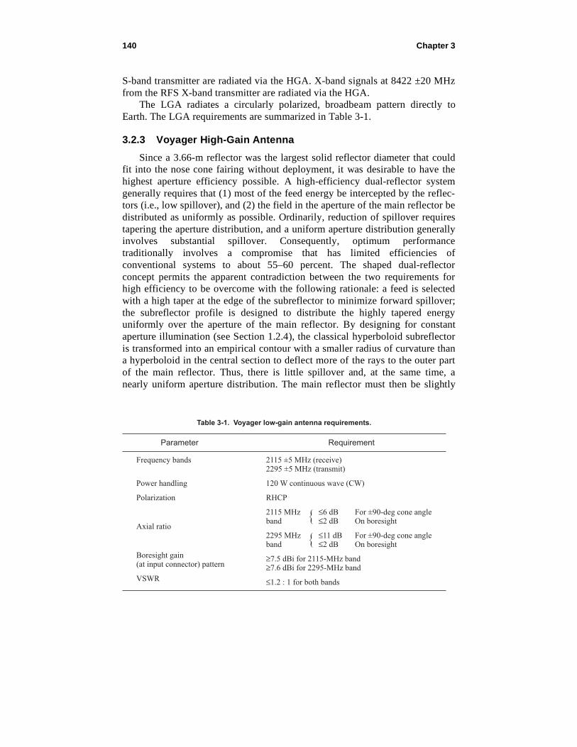
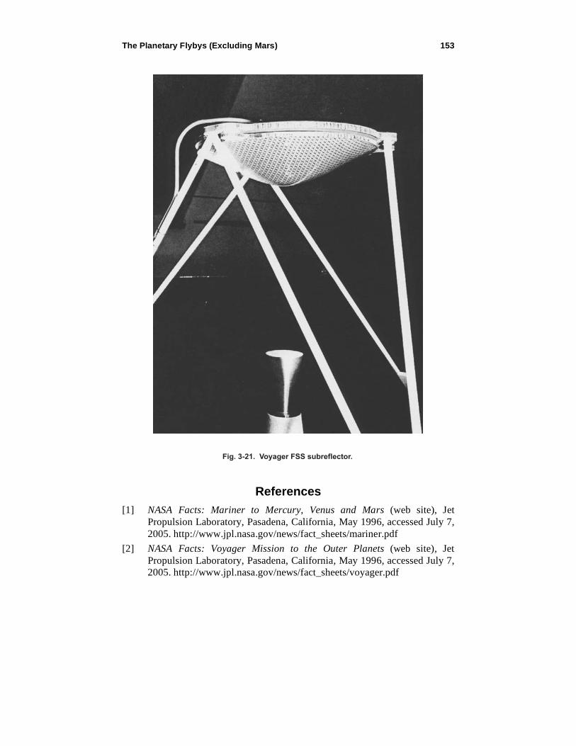
3.2.5 Voyager Frequency Selective Surface (FSS) Subreflector
The HGA utilizes prime focus/Cassegrainian geometry with an FSS to
separate the frequencies. The FSS is transparent at low frequencies to allow
prime focus operation, and it is reflective at the high frequency for
Cassegrainian operation [17]. The FSS utilizes two layers of X-band aluminum
resonant crossed dipoles printed on Mylar. The subreflector is constructed from
a Kevlar/Nomex honeycomb-core sandwich (see Fig. 3-20). The size and
geometry of the resonant dipoles are determined from flat panel tests (see
Section 1.2.5), and the second layer is used to match the lower frequency. The
performance goal was that the loss introduced at both frequency bands be less
than 0.2 dB. Measured data confirmed a loss of <0.1 dB at S-band and between
0.1 and 0.2 dB at X-band. Figure 3-21 is a picture of the FSS subreflector.
Table 3-6. Voyager HGA S-band performance summary with 0.75-in. (1.9-cm) metal struts.
RF ParameterSpecified Measured Specified Measured
2115 MHz 2295 MHz
Gain (dB)
Efficiency (percent)
Axial ratio on-axis (dB)
3-dB beamwidth (deg)
10-dB beamwidth (deg)
First sidelobe angle from boresight (deg)
First sidelobe level (dB)
VSWR (at feed)
≥35.5
≥54.2
≤2.0
2.8 ±0.3
5.2 ±0.3
≤4.3
≤−20.0
1.2 : 1
35.59
55.1
0.5
2.8
4.8
4.25
−22.2 to −26.0
1.17 : 1
≥36.3
≥55.3
≤1.5
2.6 ±0.3
4.8 ±0.3
≥4.0
≤−20.0
1.2 : 1
36.14
53.1
0.8
2.5
4.3
3.8
−20.7 to −25.5
1.20 : 1
152 Chapter 3
Fig. 3-20. Voyager FSS subreflector materials and construction.
Mylar/AL Dipole Surface on Center Contoured AreaOnly (Not on Flat ConicalSurface). Mylar on Outside
0.62 rad
0.517
Potting Kapton Tape
Nomex Honeycomb Core 1.5 lb/ft3 (24-kg/m3), 3/8-in. (0.95-cm) Cell Size Each Cell Slotted on FrontSkin Surface for Venting
Stycast 1090SIin 3 MountingInsert Areas
3 Layers of Kevlar-49/Epoxy Style 120 Fabric6 Gores/Layer(All 0 deg)
Slots in Core Cells
Mylar/AL Dipole Surface on Contoured Area Only. Mylar on Outside
FilmAdhesive0.03 lb/ft3
(24-kg/m3)
Kevlar-49/EpoxyFront Skin
Kapton Tape(Perforated)
Kevlar-49/EpoxyBack Skin
The Planetary Flybys (Excluding Mars) 153
Fig. 3-21. Voyager FSS subreflector.
References
[1] NASA Facts: Mariner to Mercury, Venus and Mars (web site), Jet
Propulsion Laboratory, Pasadena, California, May 1996, accessed July 7,
2005. http://www.jpl.nasa.gov/news/fact_sheets/mariner.pdf
[2] NASA Facts: Voyager Mission to the Outer Planets (web site), Jet
Propulsion Laboratory, Pasadena, California, May 1996, accessed July 7,
2005. http://www.jpl.nasa.gov/news/fact_sheets/voyager.pdf

154 Chapter 3
[3] The Mariner R Project: Progress Report September 1, 1961 – August 31,
1962, JPL Internal Technical Report No. 32-353, Jet Propulsion
Laboratory, Pasadena, California, also NASA-CR-135806, National
Aeronautics and Space Administration, Washington, District of
Columbia, January 1, 1963.
[4] J. N. Bryden, Mariner (Venus ’62) Flight Telecommunication System,
Technical Report No. 32-377, Jet Propulsion Laboratory, Pasadena,
California, January 15, 1963.
[5] Mariner Venus 67 Final Project Report: Volume 1. Launch through
Midcourse Maneuver, Technical Report 32-1203, Jet Propulsion
Laboratory, Pasadena, California, June 15, 1968.
[6] Past Missions - Mariner 10 (web page), Jet Propulsion Laboratory,
Pasadena, California, accessed July 7, 2005.
http://www.jpl.nasa.gov/missions/past/mariner10.html
[7] S/X Band Antenna Subsystem FDR Data Package, W.U. 33-2-1, Contract
Mariner Venus/Mercury 1973 JPL Contract 953000, contract to Jet
Propulsion Laboratory, Pasadena, California, Boeing Company, Seattle,
Washington, November 4, 1971.
[8] MVM’73-4-2017, Functional Requirement MVM’73 Spacecraft
Equipment S/X-Band Antenna Subsystem, MVM’73-4-2017 JPL Contract
953000, Contract to Jet Propulsion Laboratory, Pasadena, California,
Boeing Company, Seattle, Washington, November 14, 1971.
[9] W. A. Imbriale, Large Antennas of the Deep Space Network, Chapters 5
and 6, John Wiley & Sons, Inc., Hoboken, New Jersey, 2003.
[10] Functional Requirement Mariner Jupiter/Saturn 1977 Flight Equipment
S/X-Band Antenna Subsystem, MJS77-4-2017A, in JPL 618-205, MJS77
Functional Requirements Book (set of internal documents), Jet
Propulsion Laboratory, Pasadena, California, February 3, 1977.
[11] Mariner Jupiter/Saturn 1977 SXA Subsystem, Vol. 1, Critical Design
Review, Aeronutronic Ford Corporation, Palo Alto, California, November
1975.
[12] Mariner Jupiter/Saturn 1977 S/X-Band Antenna Subsystem, Design
Analysis Report, Volume II HGA/LGA Feed RF Analysis, WDL
Technical Report 5717, Philco-Ford Corporation, Palo Alto, California,
March 18, 1975.
[13] P. D. Potter, A New Horn with Suppressed Sidelobes and Equal
Beamwidth, Technical Report No. 32-354, Jet Propulsion Laboratory,
Pasadena, California, February 25, 1963.

The Planetary Flybys (Excluding Mars) 155
[14] A. C. Ludwig, Antennas for Space Communication, JPL SPS 37-33, Vol.
IV, Supporting Research and Advanced Development, Jet Propulsion
Laboratory, Pasadena, California, also NASA-CR-64605, National
Aeronautics and Space Administration, Washington, District of
Columbia, pp. 261–266, June 30, 1965.
[15] R. F. Thomas and D. A. Bathker, “A Dual Hybrid Horn Feedhorn for
DSN Antenna Performance Enhancement,” The Deep Space Network
Progress Report 42–22, May and June 1974, Jet Propulsion Laboratory,
Pasadena, California, pp. 101–108, August 15, 1974.
http://ipnr.jpl.nasa.gov/progress_report/
[16] Mariner Jupiter/Saturn 1977 S/X-Band Antenna Subsystem, Breadboard
Development Report Addendum A, WDL-TR5740, Aeronutronic Ford
Corporation, Palo Alto, California, August 22, 1975.
[17] G. H. Schennum, “Frequency Selective Surfaces for Multiple-Frequency
Antennas,” Microwave Journal, pp. 56–59, March 1973.


![turboecelegends.files.wordpress.com · Web view... Compare Corner reflector and Parabolic reflector. [09M/S1] 6. (a) Write short notes on ‘Folded Dipole’. (b) A six feet parabolic](https://img.dokumen.tips/doc/110x75/5ad27fe87f8b9a05208cc499/view-compare-corner-reflector-and-parabolic-reflector-09ms1-6-a-write.jpg)