Embed Size (px)
Citation preview

Chapter 3 | Sediment Basins
WSUD Engineering Procedures for Stormwater Management in Tasmania 2012 3—1
Chapter 3 Sediment Basins
Definition:Definition:Definition:Definition:
A sediment basin is a pond like structure designed to
remove coarse sediments from stormwater by
reducing flow velocities to the settling velocity of the
target sediment size.
Purpose:Purpose:Purpose:Purpose:
• To retain coarse sediments from runoff.
• Are typically the first elements in a treatment
train and play an important role by protecting
downstream elements from becoming overloaded
or smothered with sediments.
• Provide some minor flood attenuation by
providing storage.
• Where the target sediment size is below
0.125mm, low levels of hydrocarbons (that have
adhered to the particulates) will be removed.
Implementation considerations:Implementation considerations:Implementation considerations:Implementation considerations:
• Sediment basins can require considerable area to
achieve desired treatment levels of the target
particle size.
• When used for trapping sediment in runoff from
construction sites, maintenance frequency can
increase dramatically from the high sediment
yields.
• Sediment basins can have various configurations
including hard edges and base (e.g. concrete) or
a more natural form with edge vegetation
creating an attractive urban element. They are,
however, typically turbid and maintenance usually
requires significant disturbance of the system.
Maintenance involves dewatering and dredging
collected sediments. This is required approximately
every five years.
Sedimentation basins can be installed
into hard or soft landscapes

Chapter 3 | Sediment Basins
WSUD Engineering Procedures for Stormwater Management in Tasmania 2012 3—2
3.13.13.13.1 IntroductionIntroductionIntroductionIntroduction ................................................................................................................. 3—3
3.23.23.23.2 Verifying size for treatmentVerifying size for treatmentVerifying size for treatmentVerifying size for treatment ......................................................................................... 3—4
3.33.33.33.3 Design procedure: sedimentation basinsDesign procedure: sedimentation basinsDesign procedure: sedimentation basinsDesign procedure: sedimentation basins ..................................................................... 3—6
3.43.43.43.4 Checking toolsChecking toolsChecking toolsChecking tools ........................................................................................................... 3—18
3.53.53.53.5 Maintenance requirementsMaintenance requirementsMaintenance requirementsMaintenance requirements ......................................................................................... 3—23
3.63.63.63.6 Sedimentation basin worked exampleSedimentation basin worked exampleSedimentation basin worked exampleSedimentation basin worked example ........................................................................ 3—25
3.73.73.73.7 ReferencesReferencesReferencesReferences ................................................................................................................. 3—35

Chapter 3 | Sediment Basins
WSUD Engineering Procedures for Stormwater Management in Tasmania 2012 3—3
3.1 Introduction The reduction of sediment loads is a key process in protecting downstream waterways
ensuring the effective operation and long term efficiency of downstream stormwater
treatment measures (known as treatment trains). Sedimentation basins are specifically
employed to remove coarse to medium-sized sediments (generally 0.125mm and greater) by
reducing flow velocities and providing retention of these particulates.
Sedimentation basins can take various forms (generally ponds) and can be classified as any
treatment system that primarily functions to promote settling of sediments through processes
of temporary detention and reduction of flow velocities
They can be made permanent structures and incorporated into urban designs (parkland or
recreational area water features) or temporary structures to control sediment runoff during
the development of new areas.
Figure 3.1 shows the layout of a typical permanent sedimentation basin.
Figure 3.1. Sedimentation basin layout
The required treatment size of a sedimentation basin is calculated primarily on two main
factors:
1. The settling velocity of the target sediment size, and
2. The design flow at the required design rainfall intensity.

Chapter 3 | Sediment Basins
WSUD Engineering Procedures for Stormwater Management in Tasmania 2012 3—4
Analysis of typical urban catchment sediment loads suggest that between 50% to 80% of
suspended solids conveyed in urban stormwater are 125 µm or larger. Basins sized to target
these size particulates are expected to capture sediment that has low levels of contamination
(because of the larger sediment sizes) and is unlikely to require special handling and disposal.
Particular care needs to be undertaken when sizing sedimentation systems because a basin
that is under sized may have limited effectiveness (insufficient retention of particulates) and
cause smothering of downstream treatment measures reducing their treatment efficiency.
Conversely, basins that are oversized run an increased risk of excess accumulation of fine
particulates resulting in higher contaminant concentrations that could require specialist
handling facilities for maintenance (de-watering and disposal).
A further consideration in sizing a sedimentation basin is the provision of adequate storage
for settled sediment to prevent the need for frequent de-silting. A desirable maintenance
frequency for permanent facilities is once every five years (normally triggered when sediment
accumulates to half the basin depth). Temporary systems will require more frequent
maintenance depending on the catchment area and likely sediment loads.
Apart from the issues associated with the appropriate sizing of a sedimentation basin for
effective capture and retention of sediment, design considerations are similar to those for
ponds and constructed wetlands.
3.2 Verifying size for treatment Figure 3.2 shows relationships between a required basin area and design discharge for 125
µm sediment capture efficiencies of 70%, 80% and 90% using a typical shape and
configuration (λ = 0.5, see Section 4.3.2).
The influence of a permanent pool reduces flow velocities in the sedimentation basin and thus
increases detention times in the basin (and hence removal efficiency). A typical two metre
depth permanent pool was used to define the lower limit of the required sedimentation basin
thus forming three shaded areas in Figure 3.2.
The performance of typical designs of sedimentation basins can be expected to fall within the
shaded curves shown and they can be used to verify the selected size of a proposed
sedimentation basin. As the design charts relate the size of a required sedimentation basin to
a design flow, they are applicable in all regions and do not require any adjustments for the
different hydrologic regions.
The volume of a permanent pool in a sedimentation basin should have sufficient capacity to
ensure that desilting of the basin is not more frequent than once every 5 years (unless it is to
be used for temporary sediment control when cleaning every 6-months may be appropriate).
A developing catchment can be expected to discharge between 50 m3 and 200 m3 of
sediment per hectare each year. In a developed catchment, the annual sediment export is
generally one to two orders of magnitude lower with an expected mean annual rate of 1.60
m3/ha. There are different methods used to estimate sediment loads and some authorities
have produced charts of sediment loading rates (ACT Government, 1994; NSW Department of

Chapter 3 | Sediment Basins
WSUD Engineering Procedures for Stormwater Management in Tasmania 2012 3—5
Housing, 1998). Desilting is required when the permanent pool is half full with deposited
sediment.
Figure 3.2. Sedimentation Basin Area Vs Design Discharges for varying capture efficiencies of 125 µµµµm sediment

Chapter 3 | Sediment Basins
WSUD Engineering Procedures for Stormwater Management in Tasmania 2012 3—6
3.3 Design procedure: sedimentation basins
3.3.1 Estimating design flows
3.3.1.1 Design Discharges
Two, possibly three, design flows are required for sedimentation basins:
• Design operation flow – required to enable calculation of the size of the basin to allow
settling and retention of the design particulate size (Local councils and regional
catchment management authorities may stipulate the design operation flow).
• Minor system design flow - for the design of the inlet and outlet structures to ensure
system flows can be accommodated.
• Major flood flows - for the design of the basin overflow structure.
Typical design operation flows are the 1-year ARI (Average Recurrence Interval) or 2-year ARI
peak discharge, and for permanent sedimentation basins used as pre-treatments for
downstream stormwater treatment measures, this is normally the 1 year ARI peak design.
The design of inflow structures are typically based on higher ARI rainfall events as they need
to have capacity to convey the design discharge of the upstream stormwater drainage system.
In Tasmania the general design ARI for stormwater drainage systems (other than specific
flood-way or conveyance structures) is the 10 year ARI. High risk areas such as commercial,
industrial or dense residential may be designed for a 20 year ARI. Local authorities must be
consulted prior to design to confirm the desired design ARI.
All flows should be directed through a sedimentation basin so that some level of
sedimentation is achieved even during high flow conditions. In situations where the basin
forms part or a major drainage system (through flow) the capacity of the inlet and outlet
structures must be equal to or greater than the design ARI of the upstream and downstream
infrastructure. Local authorities must be consulted prior to design to confirm the design ARI
of these components.
3.3.1.2 Minor and major flood estimation
Catchment peak discharge rates can be calculated using a range of hydrologic methods. The
Rational Method Design Procedure is suitable for most, however for large catchments (greater
than 100Ha), the Kinematic Wave Equation may be employed. These methods are described in
detail in the document titled Australian Rainfall and Runoff.
Flood estimation in larger or complex catchments with multiple catchments and flow routing
requires specialist knowledge of flood estimation methods and normally involves detailed
topographical, hydrologic and hydraulic study of the catchment area. The Rational Method or
Kinematic Wave Equation should not be relied upon singly for estimation in these situations.
Chapter 3 | Sediment Basins
WSUD Engineering Procedures for Stormwater Management in Tasmania 2012 3—7
3.3.2 Size and shape of sedimentation basins
Estimating the required area (A) of a sedimentation basin may be based on the mathematical
expression derived by Fair and Geyer (1954), formulated for wastewater sedimentation basin
design:
n
A/Q
v
n
111R s
−
+−=
Equation 3.1
where R = fraction of target sediment removed
vs = settling velocity of target sediment
Q/A = rate of applied flow divided by basin surface area
n = turbulence or short-circuiting parameter
Note that Equation 3.1is strictly applicable for systems with no permanent pool, and will
generally over-estimate the required area of a sedimentation basin. This equation is thus
often considered to provide an upper limit estimate of the required size for sedimentation
basins.
In Equation 3.1the key factor for design is the ‘n’ value which is known as the turbulence
parameter. This factor takes into account the configuration of the basin (location of inlet and
outlet structures, flow spreaders, flow diversion structure for mixing etc) and the effects of
the different configurations on settling efficiency directly relating to the ability of the system
to short circuit. In order to calculate ‘n’ a hydrodynamic adjustment value (λ) must be selected
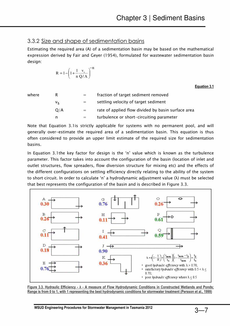
that best represents the configuration of the basin and is described in Figure 3.3.
Figure 3.3. Hydraulic Efficiency - λ - A measure of Flow Hydrodynamic Conditions in Constructed Wetlands and Ponds; Range is from 0 to 1, with 1 representing the best hydrodynamic conditions for stormwater treatment (Persson et al., 1999)
Chapter 3 | Sediment Basins
WSUD Engineering Procedures for Stormwater Management in Tasmania 2012 3—8
Figure 3.3 provides some guidance on what is considered to be good basin design with the
higher values (of λ) representing basins with good sediment retention properties, where a
value of λ greater than 0.5 should be a design objective. If the basin configuration yields a
lower value, modification to the basin configuration should be explored to increase the λ
value (e.g. inclusion of baffles, islands or flow spreaders).
The shape of the basin has a large impact on the effectiveness of the basin to retain
sediments and generally a length to width ratio of at least 3:1 should be aimed for. In
addition, the location of the inlet and outlet, flow spreaders and internal baffles impact the
hydraulic efficiency of the basin for stormwater treatment. These types of elements are noted
in Figure 3.3 as the figure “o” in diagrams O and P (which represent islands in a waterbody)
and the double line in diagram Q which represents a structure to distribute flows evenly.
DESIGN ADVICE DESIGN ADVICE DESIGN ADVICE DESIGN ADVICE ----
Consideration of maintenance access to a basin is also required when developing the
shape of a basin as this can impact the allowable width (if access is from the banks) or
the shape if access ramps into a basin are required. An area for sediment de-watering
should also be accommodated and it is required to drain back into the basin. This too
may impact on the footprint area required for a sedimentation basin system.
Once a design layout has been derived and an appropriate value of λ has been
selected, a value for ‘n’ is then calculated using the following relationship:
λ = 1 – 1/n; λ−
=1
1n
Equation 3.2
DESIGN ADVIDESIGN ADVIDESIGN ADVIDESIGN ADVICE CE CE CE ----
Good practice in the design of sedimentation basins will include a permanent pool of
water to reduce flow velocities and provide storage of settled sediment. The presence
of a permanent pool reduces flow velocities in the sedimentation basin and thus
increases detention times.
With the outlet structure being located above the bed of a sedimentation basin, it is
also not necessary for sediment particles to settle all the way to the bottom of the
basin to be effectively retained. A reasonable depth is considered to be approximately
1 m below the permanent pool level.

Chapter 3 | Sediment Basins
WSUD Engineering Procedures for Stormwater Management in Tasmania 2012 3—9
If a permanent pool is to be employed, Equation 3.1can be re-derived to account for the
effect of the permanent pool storage as follows:
n
e
pes
dd
dd
AQ
v
nR
−
+
+⋅⋅+−=
)(
)(
/
111
*
Equation 3.3
where de is the extended detention depth (m) above the permanent pool level
dp is the depth (m) of the permanent pool
d**** is the depth below the permanent pool level that is sufficient to retain the
target sediment (m) – adopt 1.0 or dp whichever is lower
R is the fraction of target sediment removed
vs is the settling velocity of target sediment
Q/A is the rate of applied flow divided by basin surface area
n is the turbulence or short-circuiting parameter
The table below lists the typical settling velocities of sediments.
Table 3-1. Settling velocities under ideal conditions
Classification of particle size Particle diameter (µm) Settling velocities (mm/s)
Very coarse sand
Coarse sand
Medium sand
Fine sand
Very fine sand
Coarse silt
Medium silt
Fine silt
Very fine silt
Clay
2000
1000
500
250
125
62
31
16
8
4
200
100
53
26
11
2.3
0.66
0.18
0.04
0.011
A further check to confirm the size of a sedimentation basin is the required volume for
storage of accumulated sediments and the impact of this volume on required cleaning
frequencies.
Loading rates (estimates of loading rates are described in Section 3.2) can then be used to
estimate the required storage volume for each clean out and this volume checked against the
allowable sediment accumulation volume given the basin configuration estimated using
Equation 3.1 or Equation 3.3. The storage volume should be estimated using half the
permanent pool volume as this level of accumulation is recommended to be adopted as the
trigger for a clean out.

Chapter 3 | Sediment Basins
WSUD Engineering Procedures for Stormwater Management in Tasmania 2012 3—10
The required volume of sediment storage (S) can be estimated using Equation 3.4:
St = Ca x R x Lo x Fr
Equation 3.4
Where: St = volume of storage required (m3)
Ca = contributing catchment area (ha)
R = capture efficiency (%), estimated from Equation 4.1 or 4.3
Lo = sediment loading rate (m3/ha/year) ********
Fr = desired cleanout frequency (years)
The fraction of sediment removed for the target pollutant (R) is assumed to represent the
fraction of the total sediment load removed. In fact, a higher fraction of coarser particles than
the target pollutant and a lower fraction for finer particles will be retained than the R-value. R
however provides a reasonable estimate of the overall sediment capture efficiency.
******** - This figure can be obtained from widely available sediment yield tables. A table should be
selected that matches the proposed development type, local soil conditions and topography.
3.3.3 Cross Sections
With the exception of temporary sedimentation basins for construction site management,
batter slopes on approaches and immediately under the water line of a basin should be
configured with the utmost consideration to public safety.
Generally there are two approaches to construction: either hard or soft edge treatments.
These can be applied individually or combined to compliment the landscape of a surrounding
area.
Soft edge treatments involve using gentle slopes to the waters edge, extending below the
water line for a distance before batter slopes steepen into deeper areas. This is illustrated in
Figure 3.4.
Figure 3.4. Illustration of a soft edge treatment for open waterbodies (GbLA, 2004)

Chapter 3 | Sediment Basins
WSUD Engineering Procedures for Stormwater Management in Tasmania 2012 3—11
An alternative to the adoption of a flat batter slope beneath the water line is to provide a 3 m
“safety bench” that is less than 0.2 m deep below the permanent pool level around the
waterbody.
Figure 3.5 shows two options for hard edge details. One has a larger vertical wall and
associated handrail for public safety and the other is a low vertical wall. In both hard edge
details, it is proposed to line the bottom of the waterbody with rock to prevent vegetation
(particularly weed) growth.
The safety requirements for individual basins may vary from site to site, and it is
recommended that an independent safety audit be conducted of each design.
Figure 3.5. Illustration of Hard Edge Treatment for Open Waterbodies (GbLA, 2004)
3.3.4 Hydraulic Structures
Hydraulic structures are required at the inlet and outlet of a sedimentation basin. Their
function is essentially one of conveyance of flow with provisions for (i) energy dissipation at
the inlet structure(s), (ii) extended detention (if appropriate) at the outlet, and (iii) overflow
pathway for above design conditions.

Chapter 3 | Sediment Basins
WSUD Engineering Procedures for Stormwater Management in Tasmania 2012 3—12
3.3.4.1 Inlet Structure
Sedimentation basins are generally configured so that flows from the upstream reticulated
system discharge directly into the basin. The inlet structure must therefore have the capacity
to adequately convey these flows. It is necessary to ensure that at the point of discharge,
energy is adequately dissipated to minimise localised scouring.
There are many methods and designs of energy dissipating and scour reducing structures and
as such they will not be covered in detail in this document. Local authorities may have
standard drawings of preferred methods of velocity reduction structures and scour protection
systems. Additionally see the resource appendices for further references.
Litter control is also normally required at an inlet structure and it is generally recommended
that some form of gross pollutant trap (GPT) be installed as part of an inlet structure. The
provision of a GPT will depend on catchment activities as well as any upstream measures in
place. There are a number of proprietary products for removing gross pollutants and these
are discussed in Chapter 7 in Australian Runoff Quality (Engineers Australia, 2006) and
additional references are provided in the resource appendices.
3.3.4.2 Outlet Structure
An outlet structure of a sedimentation basin can be configured in many ways and is
dependent on the specified operation of the system (ie. whether designed as a “stand-alone”
sedimentation basin for managing construction site runoff or as part of a wetland system).
The outlet structure generally consists of an outlet pit and discharge control structure to
control the rate of discharge from the basin under normal operation. During events that
exceed the normal design flow, the discharge control structure must have adequate capacity
to convey the design operation flow.
Structures for construction sites Structures for construction sites Structures for construction sites Structures for construction sites ––––
As a sedimentation basin for managing runoff from a construction site, landscape amenity is
not an important design outcome. Therefore, floating discharge control structures, as shown
in Figure 3.6, are considered the most effective outlets for construction sedimentation basins.
They draw flows from the surface, which generally have the lowest suspended sediment
concentrations. The discharge control structure consists of one or more slotted pipes
mounted with floats to enable them to rise with the progressive filling of the basin as shown
in Figure 3.6. Discharge from the basin is maintained at a relatively constant rate independent
of the depth of water in the basin.
Permanent applications Permanent applications Permanent applications Permanent applications ----
A weir is a more appropriate outlet structure for permanent sedimentation basins, and those
that also serve as a landscape element. Where possible, a narrow weir structure (see Figure
3.6) should be adopted to promote a larger extended detention depth range while ensuring
adequate capacity to convey the design discharge.

Chapter 3 | Sediment Basins
WSUD Engineering Procedures for Stormwater Management in Tasmania 2012 3—13
Figure 3.6. Sedimentation Basin Outlet Structures (L) a floating skimmer and (R) a narrow weir
Design considerations Design considerations Design considerations Design considerations ----
An outlet pit and associated discharge control structure should be designed with the
following considerations in mind:
• Ensure that the crest of the pit is set at or above the permanent pool level of the
sedimentation basin
• Ensure that the dimension of the pit provides discharge capacity that is greater than
or equal to the discharge capacity of the inlet structure
• Discharge capacity does not exceed that of the downstream infrastructure
• Protection is provided against blockage by flood debris
• Maintenance is simple to undertake and suitable provisions are made for access
Figure 3.7 summarises the design elements of the various components of a sedimentation
basin.
Stormwater Pipe Outfall
• Energy dissipation and
scour protection
Discharge Control Structure
• Conveyance of design operation discharge
• Setting the extended detention
depth
• Flood debris guard
Discharge Pipe
• Discharge capacity for minor drainage system design
discharge
Outlet Pit
• Discharge capacity for minor
drainage system design discharge
• Establish high flow spillway crest level
• Flood debris guard
Permanent Pool Waterbody
• Storage of deposited sediment
Embankment & Spillway
• Major drainage system design discharge
• Set spillway width and designated overflow pathway (spillway channel)
• Afflux over spillway and provision of freeboard to define top of embankment
Extended Detention Depth
Flood Storage Depth
Gross pollutant trap
• Removal of litter and
debris
Figure 3.7. Overview of Design Elements of a Sedimentation Basin and Main Design Considerations

Chapter 3 | Sediment Basins
WSUD Engineering Procedures for Stormwater Management in Tasmania 2012 3—14
Hydraulic Design of the Outlet StructureHydraulic Design of the Outlet StructureHydraulic Design of the Outlet StructureHydraulic Design of the Outlet Structure
An outlet structure is sized with a discharge capacity equal to or greater than the minor
drainage system (e.g. 5 year ARI). The two flow conditions that must be considered when
calculating the dimensions of an outlet pit are weir and orifice flow (Equations 3.5 and 3.6)
A blockage factor is also employed to account for any blockage of the structure by debris. It is
generally considered that a blockage factor of 50% reasonably represents real world
conditions.
1. Weir flow conditionWeir flow conditionWeir flow conditionWeir flow condition – when free overall conditions occur over the pit (usually when the
extended detention storage of the retarding basin is not fully engaged), ie.
5.1HCB
QP
w
des
⋅⋅=
Equation 3.5
P = Perimeter of the outlet pit
B = Blockage factor (0.5)
H = Depth of water above the crest of the outlet pit
Qdes = Design discharge (m3/s)
Cw = weir coefficient (1.7)
2. Orifice flow conditionsOrifice flow conditionsOrifice flow conditionsOrifice flow conditions – when the inlet pit is completely submerged (corresponding to
conditions associated with larger flood events), ie.
gHCB
QA
d
deso
2⋅=
Equation 3.6
Cd = Orifice Discharge Coefficient (0.6)
B = Blockage factor (0.5)
H = Depth of water above the centroid of the orifice (m)
Ao = Orifice area (m2)
Qdes = Design discharge (m3/s)
It is important that an outlet pit is prevented from blockage by debris. Design consideration
needs to include means of preventing blockage of the outlet structure.
Chapter 3 | Sediment Basins
WSUD Engineering Procedures for Stormwater Management in Tasmania 2012 3—15
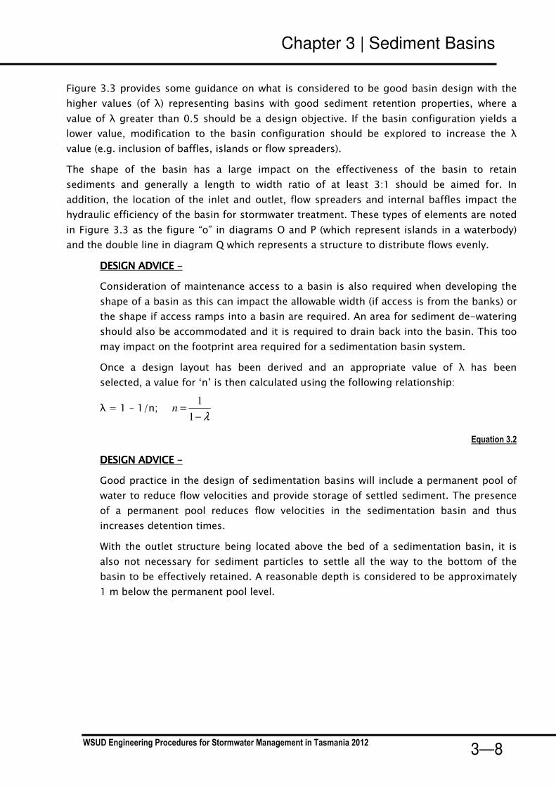
Examples of this are shown below.
Discharge Control StructureDischarge Control StructureDischarge Control StructureDischarge Control Structure
Three types of discharge control structures can be used, ie.
1. Overflow weir – the length of the weir computed with the weir flow equation (Equation
3.5) but checked to ensure that there is adequate capacity when the structure
operates under submerged conditions using the orifice flow equation (Equation 3.6).
2. Riser outlet – a vertical pipe with orifices located along the length of the pipe. The
placement of outlet orifices and determining their appropriate diameters is designed
iteratively by varying outlet diameters and levels, using the orifice equation (Equation
3.6) applied over discrete depths along the length of a riser up to the maximum
detention depth. This can be performed with a spreadsheet as illustrated in the
worked example. (see Chapter 8 for more discussion.)
3. Floating slotted pipe – the size and number of slots required to pass the operation
design flow can be computed using the orifice flow equation (Equation 3.6).
With riser-type discharge control structures, an outlet orifice is likely to be small and it is
important that these are prevented from clogging by debris. Some form of debris guard is
recommended as illustrated in the images below.

Chapter 3 | Sediment Basins
WSUD Engineering Procedures for Stormwater Management in Tasmania 2012 3—16
3.3.5 Overflow Structure
The provision of a high-flow overflow structure is an essential design element. An overflow
structure is normally a weir spillway structure. The required width of the spillway can be
computed using the weir flow equation (Equation 3.5) with the design discharge being
selected according to discussion in Section 3.3.1.1.
Figure 3.8. Overflow Structure of a Sedimentation Basin
3.3.6 Vegetation specification
Vegetation planted along the littoral zone of a sedimentation basin serve the primary function
of inhibiting public access to the open waterbody and preventing edge erosion. Terrestrial
planting beyond the littoral zone may also be recommended to screen areas and provide an
access barrier to uncontrolled areas of the stormwater treatment system.
Appendix ‘B’ provides a list of suggested plant species suitable for sedimentation basin
littoral zones in Tasmania.
3.3.7 Design calculation summary
The table on the following page provides a design calculation summary sheet for the key
design elements of a sedimentation basin to aid the design process.

Chapter 3 | Sediment Basins
WSUD Engineering Procedures for Stormwater Management in Tasmania 2012 3—17
Sedimentation BasinSedimentation BasinSedimentation BasinSedimentation Basin CALCULATION CHECKSHEETCALCULATION CHECKSHEETCALCULATION CHECKSHEETCALCULATION CHECKSHEET
CALCULATION TASK OUTCOME CHECK
1111 Identify design criteriaIdentify design criteriaIdentify design criteriaIdentify design criteriaDesign ARI Flow for inlet hydraulic structures yearDesign ARI Flow for outlet hydraulic structures year
Design ARI for overflow hydraulic structures year
2222 Catchment characteristicsCatchment characteristicsCatchment characteristicsCatchment characteristicsResidential HaCommercial Ha
Roads Ha
Fraction imperviousFraction imperviousFraction imperviousFraction imperviousResidentialCommercial
Roads
3333 Estimate design flow ratesEstimate design flow ratesEstimate design flow ratesEstimate design flow ratesTime of concentrationTime of concentrationTime of concentrationTime of concentration
estimate from flow path length and velocities minutes
Identify rainfall intensitiesIdentify rainfall intensitiesIdentify rainfall intensitiesIdentify rainfall intensitiesstation used for IFD data:
Design Rainfall Intensity for inlet structure(s) mm/hr
Design runoff coefficientDesign runoff coefficientDesign runoff coefficientDesign runoff coefficient
inlet structure(s)
Peak design flowsPeak design flowsPeak design flowsPeak design flows
Inlet structure(s) m3/s
Outlet structure(s) m3/s
Overflow structure(s) m3/s
4444 Basin Dimension and LayoutBasin Dimension and LayoutBasin Dimension and LayoutBasin Dimension and LayoutArea of sedimentation basin m
2
Aspect Ratio L:WHydraulic Efficiency
Depth of permanent pool m
Permanent Pool Volume m3
Cross Section Batter Slope V:H
5555 Basin PerformanceBasin PerformanceBasin PerformanceBasin PerformanceCapture efficiency (of 125 µm sediment) %
Sediment Cleanout Frequency years
6666 Hydrualic StructuresHydrualic StructuresHydrualic StructuresHydrualic StructuresInlet StructureInlet StructureInlet StructureInlet Structure
Provision of energy dissipation
Outlet StructureOutlet StructureOutlet StructureOutlet Structure
Pit dimension L x B
or mm diam
Discharge capacity of outlet m3/s
Provision of debris trap
Discharge PipeDischarge PipeDischarge PipeDischarge Pipe
Discharge Capacity of Discharge Pipe m3/s
7777 Spillway Spillway Spillway Spillway Discharge Capacity of Spillway m
3/s
Afflux m
Freeboard to top of embankment m

Chapter 3 | Sediment Basins
WSUD Engineering Procedures for Stormwater Management in Tasmania 2012 3—18
3.4 Checking tools This section provides a number of checking aids for designers and referral authorities. In
addition, advice on construction techniques and lessons learnt from building sediment basins
are provided.
Checklists are provided for:
• Design assessments
• Construction (during and post)
• Operation and maintenance inspections
• Asset transfer (following defects period).
3.4.1 Design assessment checklist
The checklist below presents the key design features that should be reviewed when assessing
a design of a sediment basin either for temporary or permanent use. These considerations
include configuration, safety, maintenance and operational issues that should be addressed
during the design phase.
Where an item results in an “N” when reviewing the design, referral should be made back to
the design procedure to determine the impact of the omission or error.
In addition to the checklist, a proposed design should have all necessary permits for its
installations. The referral agency should ensure that all relevant permits are in place. These
can include permits to clear vegetation, to dredge, create a waterbody, divert flows or disturb
fish or platypus habitat.
Land ownership and asset ownership are key considerations prior to construction of a
stormwater treatment device. A proposed design should clearly identify the asset owner and
who is responsible for its maintenance. The proposed owner should be responsible for
performing the asset transfer checklist (see 3.4.4).

Chapter 3 | Sediment Basins
WSUD Engineering Procedures for Stormwater Management in Tasmania 2012 3—19
Basin Location:Basin Location:Basin Location:Basin Location:
HydraulicsHydraulicsHydraulicsHydraulics
AreaAreaAreaArea Catchment
Area (ha):
Basin Area (ha)
YYYY NNNN
YYYY NNNN
YYYY NNNN
Outlet perimeter >= design discharge of outlet pipe?
Discharge pipe from has sufficient capacity to convey the
maintenance drain flows or Q1 flows (whichever is higher)?
Protection against clogging of orifice provided on outlet
structure?
Outlet configuration suitable for basin type (eg riser for
construction sediment, weir for wetland pretreatment etc)?
Riser diameter sufficient to convey Q1 flows when operating
as a “glory hole” spillway?
Maintenance drain provided?
Freeboard provided above extended detention depth?
Hydraulic StructuresHydraulic StructuresHydraulic StructuresHydraulic Structures
Public access to inlet zone prevented through vegetation or
other means?
Gross pollutant protection measures provided on inlet
structures?
Batter slopes shallow or safety bench provided in case of
accidental entry into basin?
Maintenance access allowed for into base of sediment
basin?
Scour protection provided at inlet?
Configuration of basin (aspect, depth and flows) allows
settling of particles >125Um?
Basin ConfigurationBasin ConfigurationBasin ConfigurationBasin Configuration
Inlet pipe/structure sufficient for maximum design flow
(minor and/or major flood event)?
Basin capacity sufficient for maintenance period >=5
years?
Treatment performance verified from curves?
Minor Flood:
(m3/s)
Sediment Basin Design Assessment ChecklistSediment Basin Design Assessment ChecklistSediment Basin Design Assessment ChecklistSediment Basin Design Assessment Checklist
Major Flood:
(m3/s)
TreatmentTreatmentTreatmentTreatment

Chapter 3 | Sediment Basins
WSUD Engineering Procedures for Stormwater Management in Tasmania 2012 3—20
3.4.2 Construction advice
This section provides general advice for the construction of sedimentation basins. It is based
on observations from actual construction projects around Australia.
Building phase damage
It is important to have protection from upstream flows during construction of a sediment
basin. A mechanism to divert flows around a construction site and to provide protection from
litter and debris is required.
High flow contingencies
Contingencies to manage risks associated with flood events during construction are required.
All machinery should be stored above acceptable flood levels and the site stabilised as best as
possible at the end of each day as well as plans for de-watering following storms made.
Maintenance access
An important component of a sediment basin is accessibility for maintenance. Should
excavators be capable of reaching all parts of the basin an access track may not be required
to the base of the inlet zone, however an access track around the perimeter of the basin
would be required. If sediment collection is by using earthmoving equipment, then a stable
ramp will be required into the base of the inlet zone (maximum slope 1:10).
Solid base
To aid maintenance it is recommended to construct the inlet zone either with a hard (ie rock
or concrete) bottom or a distinct sand layer. These serve an important role for determining
the levels that excavation should extend to during sediment removal (i.e. how deep to dig) for
either systems cleaned from the banks or directly accessed. Hard bases are also important if
maintenance is by driving into the basin.
De-watering removed sediments
An area should be constructed that allows for de-watering of removed sediments from a
sediment basin. This allows the removed sediments to be transported as ‘dry’ material and
can greatly reduce disposal costs compared to liquid wastes. This area should be located such
that water from the material drains back into the basin. Material should be allowed to drain
for a minimum of overnight before disposal.
Inlet checks
It is good practice to check the operation of inlet erosion protection measures following the
first few rainfall events. It is important to check for these early in the systems life, to avoid
continuing problems. Should problems occur in these events the erosion protection should be
enhanced.

Chapter 3 | Sediment Basins
WSUD Engineering Procedures for Stormwater Management in Tasmania 2012 3—21
3.4.3 Construction checklist
SITE:
CONSTRUCTED BY:
Items inspected Satisfactory Unsatisfactory Satisfactory Unsatisfactory
Preliminary works Y N Structural components Y N
16. Location and levels of outlet as designed
17. Safety protection provided
2. Limit public access 18. Pipe joints and connections as designed
3. Location same as plans 19. Concrete and reinforcement as designed
4. Site protection from existing flows 20. Inlets appropriately installed
Earthworks 21. Inlet energy dissipation installed
5. Integrity of banks 22. No seepage through banks
6. Batter slopes as plans 23. Ensure spillway is level
7. Impermeable (solid) base installed 24. Provision of maintenance drain
8. Maintenance access (eg. ramp) installed 25. Collar installed on pipes
9. Compaction process as designed Vegetation
27. Weed removal before stabilisation
1. Confirm levels of inlets and outlets 6. Check for uneven settling of banks
2. Confirm structural element sizes 7. Inlet erosion protection working
3. Check batter slopes 8. Maintenance access provided
4. Vegetation as designed
5. Draining area for maintenance provided
COMMENTS ON INSPECTION
ACTIONS REQUIRED
1. Erosion and sediment control plan adopted
26. Planting as designed (species and
densities)
FINAL INSPECTION
9. Construction generated sediment removed
CONSTRUCTION INSPECTION
CHECKLIST
Checked
Sediment basin
CONTACT DURING VISIT:
INSPECTED BY:
DATE:
TIME:
WEATHER:
DURING CONSTRUCTIONChecked
25. Stablisation immediately following
earthworks
4.
5.
6.
1.
2.
3.
10. Levels of base, banks and spillway as
designed

Chapter 3 | Sediment Basins
WSUD Engineering Procedures for Stormwater Management in Tasmania 2012 3—22
3.4.4 Asset transfer checklist
Asset Location:Asset Location:Asset Location:Asset Location:
Construction by:Construction by:Construction by:Construction by:
Defects and Liability Defects and Liability Defects and Liability Defects and Liability
PeriodPeriodPeriodPeriodYYYY NNNN
YYYY NNNN
YYYY NNNN
Digital files (eg drawings, survey, models) provided?
Design Assessment Checklist provided?
As constructed plans provided?
Asset listed on asset register or database?
Proprietary information provided (if applicable)?
Copies of all required permits (both construction and operational)
submitted?
Asset InformationAsset InformationAsset InformationAsset Information
Asset Handover ChecklistAsset Handover ChecklistAsset Handover ChecklistAsset Handover Checklist
TreatmentTreatmentTreatmentTreatment
Asset inspected for defects?
Inspection and maintenance undertaken as per maintenance plan?
Inspection and maintenance forms provided?
MaintenanceMaintenanceMaintenanceMaintenance
Maintenance plans provided for each asset?
System appears to be working as designed visually?
No obvious signs of under-performance?

Chapter 3 | Sediment Basins
WSUD Engineering Procedures for Stormwater Management in Tasmania 2012 3—23
3.5 Maintenance requirements Sediment basins treat runoff by slowing flow velocities and promoting settlement of coarse to
medium sized sediments. Maintenance revolves around ensuring inlet erosion protection is
operating as designed, monitoring sediment accumulation and ensuring that the outlet is not
blocked with debris.
Inspections of the inlet configuration following storm events should be made soon after
construction to check for erosion. In addition, regular checks of sediment build up will be
required as sediment loads from developing catchments or construction sites vary
enormously. The basins should be cleaned out if more than half full of accumulated sediment.The basins should be cleaned out if more than half full of accumulated sediment.The basins should be cleaned out if more than half full of accumulated sediment.The basins should be cleaned out if more than half full of accumulated sediment.
Similar to other types of practices, debris removal is an ongoing maintenance function.
Debris, if not removed, can block inlets or outlets, and can be unsightly if located in a visible
location. Inspection and removal of debris should be done regularly, but debris should be
removed whenever it is observed on the site.
3.5.1 Operation & maintenance inspection form
The form below should be used whenever an inspection is conducted and kept as a record on
the asset condition and quantity of removed pollutants over time.

Chapter 3 | Sediment Basins
WSUD Engineering Procedures for Stormwater Management in Tasmania 2012 3—24
Inspection Inspection Inspection Inspection
Frequency:Frequency:Frequency:Frequency:3 monthly3 monthly3 monthly3 monthly
Date of Date of Date of Date of
Visit:Visit:Visit:Visit:
Location:Location:Location:Location:
Description:Description:Description:Description:
Site Visit by:Site Visit by:Site Visit by:Site Visit by:
YYYY NNNN Action Required (details)Action Required (details)Action Required (details)Action Required (details)
Sediment Basin Maintenance ChecklistSediment Basin Maintenance ChecklistSediment Basin Maintenance ChecklistSediment Basin Maintenance Checklist
Overflow structure integrity satisfactory?
Evidence of dumping (building waste, oils etc)?
Terrestrial vegetation condition satisfactory (density, weeds etc)?
Inspection ItemsInspection ItemsInspection ItemsInspection Items
Litter within inlet or open water zones?
Sediment within inlet zone requires removal (record depth, remove if
>50%)?
Maintenance drain operational (check)?
Comments:
Weeds require removal from within basin?
Settling or erosion of bunds/batters present?
Damage/vandalism to structures present?
Outlet structure free of debris?

Chapter 3 | Sediment Basins
WSUD Engineering Procedures for Stormwater Management in Tasmania 2012 3—25
3.6 Sedimentation basin worked example
3.6.1 Worked example introduction
A sedimentation basin and wetland system is proposed to treat runoff from a highway. This
worked example focuses on the sediment basin (inlet zone) component of the system.
The site is triangular in shape with a surface area of 500 m2 as shown in Figure 3.9. Road
runoff is conveyed by stormwater pipes (design capacity up to the 100 year ARI event) and
there are two highway outfall pipes that discharge to the two top apexes of the site. Each
outfall services about 1km of the highway with the total contributing area of 4Ha (90%
impervious) to each outfall. The site of the site has a fall of approximately 2m (from 5m to 3m
AHD) towards a degraded watercourse.
Site constraints limit the size available for the stormwater treatment system therefore it is
important to ensure that the size of the inlet zones (ie. sedimentation basins) are not
compromised, to ensure that larger sediments are effectively trapped and prevented from
smothering the planted zone (thereby creating future maintenance problems).
The consequence of this action is the reduction in the overall hydrologic effectiveness of the
system (i.e. the proportion of mean annual runoff subjected to the full wetland treatment),
but not its functional integrity.
All stormwater runoff will be subjected to primary treatment, by sedimentation of coarse to
medium size sediment. The inlet zone will operate under by-pass conditions more often
owing to a smaller macrophyte zone in this case.
Freeway Carriageway
Creek
Site of Sedimentation Basin & Wetland
System
6.0
5.0
4.0
3.0
50 m
20 m
Freeway Carriageway
Creek
Site of Sedimentation Basin & Wetland
System
6.0
5.0
4.0
3.0
50 m
20 m
Figure 3.9Layout of Proposed site for Sedimentation Basin
Inlet 1
Inlet 2

Chapter 3 | Sediment Basins
WSUD Engineering Procedures for Stormwater Management in Tasmania 2012 3—26
3.6.1.1 Design Objectives
As the sedimentation basins form part of a treatment train (with a small macrophyte wetland),
sizing to meet the overall best practice stormwater quality objectives does not apply. Instead,
the design requirements of the sedimentation basin system are to:
• Promote sedimentation of particles larger than 125µm (0.125mm) with a 90% capture
efficiency for flows up to the 1-year ARI (un-attenuated) peak discharge.
• Provide for connection to the downstream macrophyte wetland zone with discharge
capacity corresponding to the 1-year ARI (un-attenuated) peak discharge.
• Provide for by-pass operation when the inundation of the downstream macrophyte
wetland zone reaches the design maximum extended detention depth with a discharge
capacity corresponding to the 100-year ARI peak discharge.
Analyses to be undertaken during the detailed design phase include the following:
• Sizing the sedimentation basin (depth and area) using sedimentation theory (an
extended detention depth of 0.25m0.25m0.25m0.25m above the permanent pool level has been
nominated to match the proposed maximum water level of the downstream
macrophyte zone)
• Configure the layout of the basin such that the system hydraulic efficiency (see figure
3.3) can be optimised
• Design of the inlet structure to provide for energy dissipation of inflows up to the 100
year ARI peak discharge
• Design of by-pass structure to provide for flow by-pass of downstream wetland for
events up to the 100 year ARI event
• Design of the basin outlet structure connecting to the macrophyte wetland zone,
including debris trap.
In addition, landscape design will be required and this will include the following:
• Littoral zone vegetation
• Terrestrial vegetation
Chapter 3 | Sediment Basins
WSUD Engineering Procedures for Stormwater Management in Tasmania 2012 3—27
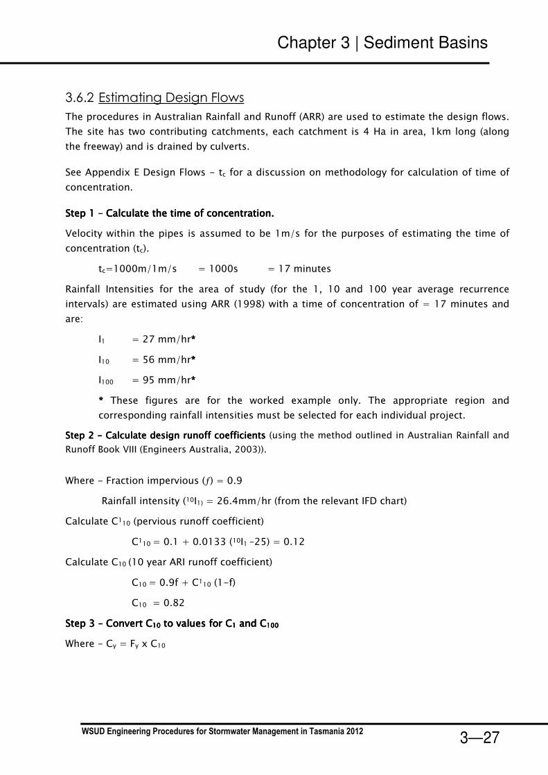
3.6.2 Estimating Design Flows
The procedures in Australian Rainfall and Runoff (ARR) are used to estimate the design flows.
The site has two contributing catchments, each catchment is 4 Ha in area, 1km long (along
the freeway) and is drained by culverts.
See Appendix E Design Flows - tc for a discussion on methodology for calculation of time of
concentration.
Step 1 Step 1 Step 1 Step 1 –––– Calculate the time of concentration.Calculate the time of concentration.Calculate the time of concentration.Calculate the time of concentration.
Velocity within the pipes is assumed to be 1m/s for the purposes of estimating the time of
concentration (tc).
tc=1000m/1m/s = 1000s = 17 minutes
Rainfall Intensities for the area of study (for the 1, 10 and 100 year average recurrence
intervals) are estimated using ARR (1998) with a time of concentration of = 17 minutes and
are:
I1 = 27 mm/hr****
I10 = 56 mm/hr****
I100 = 95 mm/hr****
**** These figures are for the worked example only. The appropriate region and
corresponding rainfall intensities must be selected for each individual project.
Step 2 Step 2 Step 2 Step 2 –––– Calculate design runoff coefficientsCalculate design runoff coefficientsCalculate design runoff coefficientsCalculate design runoff coefficients (using the method outlined in Australian Rainfall and
Runoff Book VIII (Engineers Australia, 2003)).
Where - Fraction impervious (ƒ) = 0.9
Rainfall intensity (10I1) = 26.4mm/hr (from the relevant IFD chart)
Calculate C110 (pervious runoff coefficient)
C110 = 0.1 + 0.0133 (10I1 –25) = 0.12
Calculate C10 (10 year ARI runoff coefficient)
C10 = 0.9f + C110 (1-f)
C10 = 0.82
Step 3 Step 3 Step 3 Step 3 –––– Convert CConvert CConvert CConvert C10101010 to values for Cto values for Cto values for Cto values for C1111 and Cand Cand Cand C100100100100
Where - Cy = Fy x C10

Chapter 3 | Sediment Basins
WSUD Engineering Procedures for Stormwater Management in Tasmania 2012 3—28
Runoff coefficients as per Table 1.6 Book VIII ARR 1998
ARI (years) Frequency Factor, Fy Runoff Coefficient, Cy
1 0.8 0.66
10 1.0 0.82
100 1.2 0.98
Step 4 Step 4 Step 4 Step 4 –––– Calculate peak design flow (calculated using the Rational Method). Calculate peak design flow (calculated using the Rational Method). Calculate peak design flow (calculated using the Rational Method). Calculate peak design flow (calculated using the Rational Method).
360
CIAQ =
Where - C is the runoff coefficient (C1, C10 and C100)
I is the design rainfall intensity mm/hr (I1 , I10 and I100)
A is the catchment area (Ha)
Q1 = 0.20m3/s
Q10 = 0.51m3/s
Q100 = 1.0 m3/s
Operation Design Discharge = 0.20 m3/s
Design discharge for connection to microphyte zone = 0.20 m3/s
Spillway Design Discharge = 1.0 m3/s
3.6.3 Size and Shape of Sedimentation Basin
The inlet zone is to be sized to remove at least 90% of 125Um particles for the peak 1-year
flow.
Pollutant removal is estimated using the following:
n
e
pes
dd
dd
AQ
v
nR
−
+
+⋅⋅+−=
)(
)(
/
111
*
An aspect ratio of 1 (w) to 4 (L) is adopted based on the available space (Figure 3.9). Using Equation 3.2, the hydraulic efficiency (λ) is estimated to be 0.4. This value is less than desirable, however, site constraints prevent any other
configuration. The turbulence factor (n) is computed from Equation 3.2
Hydraulic efficiency (λ) = 0.4
Turbulence factor (n) = 1.67
The proposed extended detention depth of the basin is 0.25 (as outlined in Section 3.6.1) and
a notional permanent pool depth of 2 m has been adopted, ie.
dp = 2.0 m
d**** = 1.0m
de = 0.25m
Vs = 0.011m/s for 125Um particles
Q = Design operation flow rate = 0.20 m3/s

Chapter 3 | Sediment Basins
WSUD Engineering Procedures for Stormwater Management in Tasmania 2012 3—29
From above, the required sedimentation basin area to achieve target sediment (125 µm)
capture efficiency of 90% is 50 m2. With a W to L ratio of 1:4, the notional dimensions of the
basin are 3.5 m x 14 m. This figure correlates with the graph above.
The available sediment storage is 50 x 2 = 100 m3. Cleanout is to be scheduled when the
storage is half full, therefore the available sediment storage prior to clean out is 50m3.
The required volume of sediment storage to ensure cleaning is not required more frequently
than every five years is estimated using Equation 3.4 (using a sediment discharge rate of 1.6
m3/Ha/yr).
Require storage (St) = Ca x R x Lo x Fr
= 4 x 0.9 x 1.6 x 5 = 29 m3
Available storage volume is 50m3, therefore it is OK.
The required clean out frequency is estimated to be (by rearranging Equation 3.4):
Frequency of basin desilting = 6.89.046.1
1005.0=
××
× years > 5 years � OK
Open Water Area = 50 m2
Width = 3.5 m; Length = 12 m
Depth of Permanent Pool (dp) = 2.0 m
Depth of Extended Detention (de) = 0.25m

Chapter 3 | Sediment Basins
WSUD Engineering Procedures for Stormwater Management in Tasmania 2012 3—30
3.6.4 Hydraulic Structure design
3.6.4.1 Inlet Structure
To prevent scour of deposited sediments from flows in the inlet pipes, it is necessary to limit
velocities adjacent to the inlet to below 1m/s. Culvert invert assumed to be RL 3.5m AHD
Rock beaching will be required in this area to ensure that excessive scour does not occur.
Provide energy dissipation and erosion protection in the form of rock
beaching at the inlet structure; Qdes = 0.51 m3/s.
3.6.4.2 Outlet Structure
The outlet structure is to consist of an outlet pit with the top of the pit set at the permanent
pool level, creating a permanent pool depth of 2 m. The dimension of the pit should ensure
adequate discharge capacity to discharge the design flow for the connection to the
macrophyte zone (ie. 1 year ARI peak discharge of 0.2 m3/s).
According to section 3.3.4.2, two possible flow conditions need to be checked, i.e. weir flow
conditions (with extended detention of 0.25 m) and orifice flow conditions.
Stormwater
pipe
25 mm dia.
weephole
Concrete
outlet apron
Place nom. 100 mm diarock to bottom of batter
Wing Wall
Plan Inlet Structure Section Inlet Structure
Stormwater
pipe
25 mm dia.
weephole
Concrete
outlet apron
Place nom. 100 mm diarock to bottom of batter
Wing Wall
Plan Inlet Structure Section Inlet Structure

Chapter 3 | Sediment Basins
WSUD Engineering Procedures for Stormwater Management in Tasmania 2012 3—31
Weir Flow Conditions
From Equation 3.5
, the required perimeter of the outlet pit to pass 0.2 m3/s with an afflux of 0.25 m can be
calculated:-
5.1HCB
QP
w
des
⋅⋅= = 88.1
25.07.15.0
2.05.1
=⋅⋅
m
Orifice Flow Conditions
From Equation 3.6, the required area of the outlet pit can be calculated as follows:-
gHCB
QA
d
deso
2⋅= =
)25.0(26.05.0
2.0
g⋅= 0.30 m2
Adopt 600 x 600 mm pit: Area = 0.36 m2; Perimeter = 2.4 m; Qcap = 0.24 m3/s � OK
The top of the pit should be fitted with a standard grating to prevent flood debris from
blocking the outlet pit.
Outlet Pit = 600 x 600 mm diameter with standard grating
3.6.4.3 Overflow Structure
The overflow structure must be capable of conveying the Q100 peak flow. A weir with a crest
elevation set at 0.25 m (ie. de) above the permanent pool level, and an afflux of 300mm has
been adopted in order to calculate the required length of the spillway weir.

Chapter 3 | Sediment Basins
WSUD Engineering Procedures for Stormwater Management in Tasmania 2012 3—32
It is common practice to allow for 300 mm of freeboard above the afflux level when setting
the top of embankment elevation. This value was adopted as a trade off between the bank
height and the width of the weir. A bank height of 600mm (300mm afflux and 300mm
freeboard) above the normal water level was deemed acceptable. The length is calculated
using the weir flow equation with a weir coefficient of 1.7, i.e.
5.1HC
QL
w
des
⋅= =
5.13.07.1
0.1
⋅= 3.6 m
Bypass weir is located adjacent to inflow culvert to minimise risk of sediment scour.
Spillway length = 3.6 m set at 0.25 m above permanent pool level
Top of embankment set at 0.6 m above the permanent pool level.
3.6.4.4 Discharge to Macrophyte Zone
A culvert connection between the sedimentation basin (inlet zone) and macrophyte zone will
also need to be designed with the design criterion that the culvert will need to have adequate
capacity to pass the 1 year ARI peak discharge when the water level in macrophyte zone is at
its permanent pool level. This will also provide the flow control into the wetland.
The design calculation and configuration of this connection is described in Chapter 8 on
constructed wetland design.

Chapter 3 | Sediment Basins
WSUD Engineering Procedures for Stormwater Management in Tasmania 2012 3—33
Sedimentation BasinSedimentation BasinSedimentation BasinSedimentation Basin CALCULATION CHECKSHEETCALCULATION CHECKSHEETCALCULATION CHECKSHEETCALCULATION CHECKSHEET
CALCULATION TASK OUTCOME CHECK
1111 Identify design criteriaIdentify design criteriaIdentify design criteriaIdentify design criteria �
Design ARI Flow for inlet hydraulic structures 10 year
Design ARI Flow for outlet hydraulic structures 1 year
Design ARI for overflow hydraulic structures 100 year
2222 Catchment characteristicsCatchment characteristicsCatchment characteristicsCatchment characteristics �
Residential 0 Ha
Commercial 0 Ha
Roads 4 Ha
Fraction imperviousFraction imperviousFraction imperviousFraction impervious �
Residential N/A
Commercial N/A
Roads 0.9
3333 Estimate design flow ratesEstimate design flow ratesEstimate design flow ratesEstimate design flow ratesTime of concentrationTime of concentrationTime of concentrationTime of concentration
estimate from flow path length and velocities 17 minutes �
Identify rainfall intensitiesIdentify rainfall intensitiesIdentify rainfall intensitiesIdentify rainfall intensitiesstation used for IFD data: Hobart
Design Rainfall Intensity for inlet structure(s) 27 to 56 mm/hr �
Design runoff coefficientDesign runoff coefficientDesign runoff coefficientDesign runoff coefficient
inlet structure(s) 0.66 to 0.98 �
Peak design flowsPeak design flowsPeak design flowsPeak design flows �
Inlet structure(s) 0.51 m3/s
Outlet structure(s) 0.20 m3/s
Overflow structure(s) 1.00 m3/s
4444 Basin Dimension and LayoutBasin Dimension and LayoutBasin Dimension and LayoutBasin Dimension and Layout �
Area of sedimentation basin 50 m2
Aspect Ratio 4(L):1(W) L:W
Hydraulic Efficiency 0.4
Depth of permanent pool 2 m
Permanent Pool Volume 100 m3
Cross Section Batter Slope 1(V):8(H) V:H
5555 Basin PerformanceBasin PerformanceBasin PerformanceBasin Performance �
Capture efficiency (of 125 µm sediment) 90 %
Sediment Cleanout Frequency 8.6 years
6666 Hydrualic StructuresHydrualic StructuresHydrualic StructuresHydrualic Structures
Inlet StructureInlet StructureInlet StructureInlet Structure �
Provision of energy dissipation Y
Outlet StructureOutlet StructureOutlet StructureOutlet Structure �
Pit dimension 600 x 600 L x B
or mm diam
Discharge capacity of outlet 0.21 m3/s
Provision of debris trap Y
Discharge PipeDischarge PipeDischarge PipeDischarge Pipe �
Discharge Capacity of Discharge Pipe 0.2 m3/s
7777 Spillway Spillway Spillway Spillway �
Discharge Capacity of Spillway 1 m3/s

Chapter 3 | Sediment Basins
WSUD Engineering Procedures for Stormwater Management in Tasmania 2012 3—34
3.6.5 Construction drawings

Chapter 3 | Sediment Basins
WSUD Engineering Procedures for Stormwater Management in Tasmania 2012 3—35
3.7 References ACT Government, 1994, Standard Engineering Practices: Urban Stormwater, Edition 1
Chow, V.T., 1959, Open-Channel Hydraulics, McGraw-Hill Book Co.
Engineers Australia, 2006, Australian Runoff Quality Guidelines: A Guide to Water Sensitive
Urban Design, Editor in Chief, Wong, T.H.F., National Committee for Water Engineering
Fair G.M. and Geyer J.C., 1954, Water Supply and Waste Disposal, John Wiley and Sons, New
York, Vol. 2
Graeme Bentley Landscape Architects (GbLA), 2004, Preliminary drawings for Mernda Wetland,
Report for Stockland
Henderson, F.M., 1966, Open Channel Flow, Macmillan Publishing, New York
Institution of Engineers Australia, 1997, Australian Rainfall and Runoff – A guide to flood
estimation, Editor in Chief – Pilgram, D.H.
NSW Department of Housing, 1998, Managing Urban Stormwater: Soils and Construction, 3rd
Edition
Persson, J., Somes, N.L.G. and Wong T.H.F., 1999, Hydraulic efficiency and constructed
wetland and ponds, Water Science and Technology Vol 40 No 3 pp 291–289


