Embed Size (px)
Citation preview

Chapter 3
PROPERTIES OF PURE SUBSTANCES
IINNTTRROODDUUCCTTIIOONN
The pure substance is a system which is (i) homogenous in composition, (ii) homogenous in chemical aggregation, and (iii) invariable in chemical aggregation. Homogenous in composition means that the composition of each part of the system is the same as the composition of every other part. Composition means the relative proportions of the chemical elements into which the sample can be analyzed. It does not matter how these elements are combined.
Figure 3-0-1: Illustrating the definition of a pure substance
For example in figs 3.1 system (a), comprising steam and water, is homogenous in composition, since chemical analysis would reveal that hydrogen and oxygen atoms are presents in the ratio 3.1 whether the sample be taken from the steam or from the steam or from the water. The same is true of system.
(b) Containing uncombined hydrogen and oxygen gas in the atomic ratio 3.1 in the upper part, and water in the lower part. System (c) however, is not homogenous in composition, for the hydrogen and oxygen are present in the ratio 1:1 in the upper part, but in the ratio 3:1 (as water) in the lower part.

“Homogenous in chemical aggregation” means that the chemical elements must be combined chemically in the same way in all parts of the system. Consideration of Fig.3.1 again shows that the system (a) satisfies this condition also; for steam and water consist of identical molecules. System (b) on the other hand is not homogeneous in chemical aggregation since in the upper part of the system the hydrogen and oxygen are not combined chemically (individual atoms of H and O are not uniquely associated), whereas in the lower part of the system the hydrogen and oxygen are combined to form water.
Note however that a uniform mixture of steam, hydrogen gas, and oxygen gas would be regarded as homogeneous in both composition and chemical aggregation whatever the relative proportions of the components.
“Invariable in chemical aggregation” means that the state of chemical combination of the system does not change with time (condition (ii) referred to variation with position). Thus a mixture of hydrogen and oxygen which changed into steam during the time that the system was under consideration would not be a pure substance.
PP––VV––TT RREELLAATTIIOONN
We begin our study of the properties of pure, simple compressible substances and the relations among these properties with pressure, specific volume, and temperature. From experiment it is known that temperature and specific volume can be regarded as independent and pressure determined as a function of these two: p _ p (T, v). The graph of such a function is a surface, the p–v–T surface.
P–v–T Surface Figure 3.1 is the p–v–T surface of a substance such as water that expands on freezing. Figure 3.2 is for a substance that contracts on freezing and most substances exhibit this characteristic.
The coordinates of a point on the p–v–T surfaces represent the values that pressure, specific volume, and temperature would assume when the substance is at equilibrium.

Figure 3-0-2: p–v–T surface and projections for a substance that expands on freezing.
Three-dimensional view. (b) Phase diagram. (c) p–v diagram.
There are regions on the p–v–T surfaces of Figs. 3. and 3.3 labelled solid, liquid, and vapour. In these single-phase regions, the state is fixed by any two of the properties: pressure, specific volume, and temperature, since all of these are independent when there is a single phase present. Located between the single-phase regions are two-phase regions where two phases exist in equilibrium: liquid–vapour, solid–liquid, and solid–vapour. Two phases can coexist during changes in phase such as vaporization, melting, and sublimation. Within the two phase regions pressure and temperature are not independent; one cannot be changed without changing the other. In these regions the state cannot be fixed by temperature and pressure alone; however, the state can be fixed by specific volume and either pressure or temperature.
Three phases can exist in equilibrium along the line labelled triple line.
A state at which a phase change begins or ends is called a saturation state. The dome shaped region composed of the two-phase liquid–vapour states is called the vapour dome. The lines bordering the vapour dome are called saturated liquid and saturated vapour lines. At the top of the dome, where the saturated liquid and saturated vapour lines meet, is the critical point. The critical temperature Tc of a pure substance is the maximum temperature at which liquid and vapour phases can coexist in equilibrium. The pressure at the critical point is called

Figure 3-0-3: p–v–T surface and projections for a substance that contracts
On freezing. (a) Three-dimensional view. (b) Phase diagram. (c) p–v diagram.
The critical pressure, pc. The specific volume at this state is the critical specific volume. Values of the critical point properties for a number of substances are given in Tables A-1 located in the Appendix.
The three-dimensional p–v–T surface is useful for bringing out the general relationships among the three phases of matter normally under consideration. However, it is often more convenient to work with two-dimensional projections of the surface. These projections are considered next.
SSTTEEAAMM FFOORRMMAATTIIOONN AANNDD RREELLAATTIINNGG TTEERRMMSS
The process of formation of steam is discussed below:
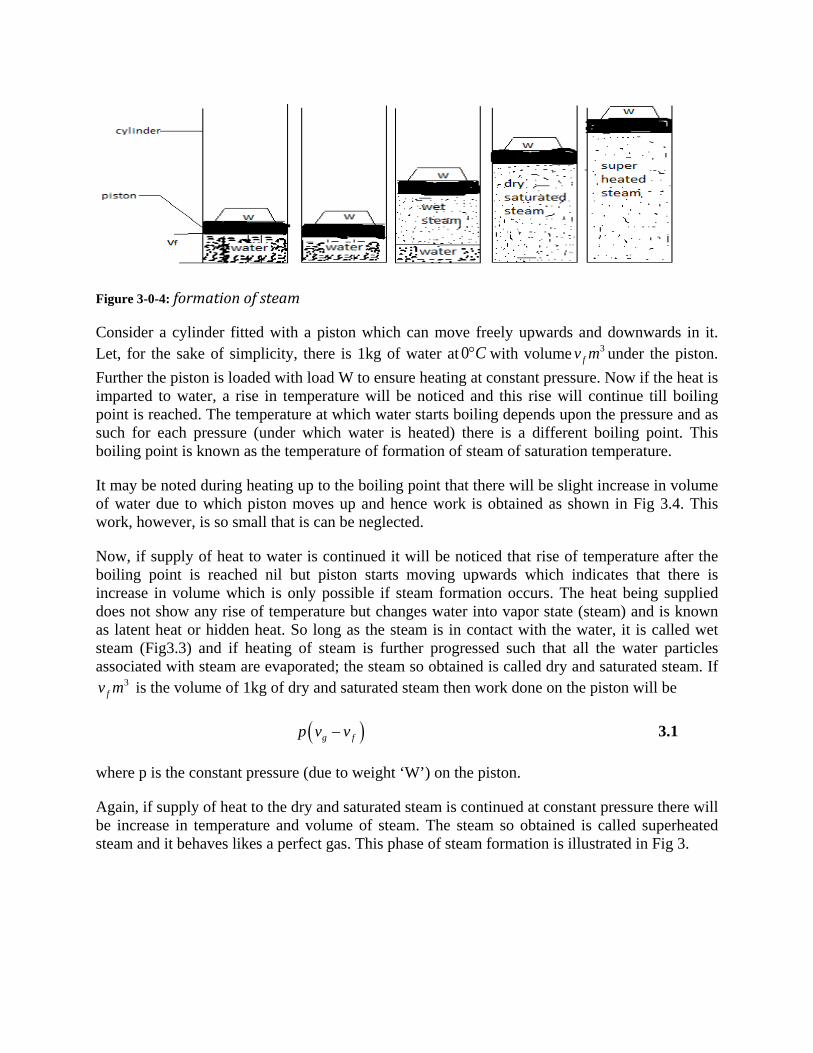
Figure 3-0-4: formation of steam
Consider a cylinder fitted with a piston which can move freely upwards and downwards in it. Let, for the sake of simplicity, there is 1kg of water at 0 C° with volume 3
fv m under the piston. Further the piston is loaded with load W to ensure heating at constant pressure. Now if the heat is imparted to water, a rise in temperature will be noticed and this rise will continue till boiling point is reached. The temperature at which water starts boiling depends upon the pressure and as such for each pressure (under which water is heated) there is a different boiling point. This boiling point is known as the temperature of formation of steam of saturation temperature.
It may be noted during heating up to the boiling point that there will be slight increase in volume of water due to which piston moves up and hence work is obtained as shown in Fig 3.4. This work, however, is so small that is can be neglected.
Now, if supply of heat to water is continued it will be noticed that rise of temperature after the boiling point is reached nil but piston starts moving upwards which indicates that there is increase in volume which is only possible if steam formation occurs. The heat being supplied does not show any rise of temperature but changes water into vapor state (steam) and is known as latent heat or hidden heat. So long as the steam is in contact with the water, it is called wet steam (Fig3.3) and if heating of steam is further progressed such that all the water particles associated with steam are evaporated; the steam so obtained is called dry and saturated steam. If
3fv m is the volume of 1kg of dry and saturated steam then work done on the piston will be
( )g fp v v− 3.1
where p is the constant pressure (due to weight ‘W’) on the piston.
Again, if supply of heat to the dry and saturated steam is continued at constant pressure there will be increase in temperature and volume of steam. The steam so obtained is called superheated steam and it behaves likes a perfect gas. This phase of steam formation is illustrated in Fig 3.

Terms 1. Sensible heat of water( fh ): It is defined as the quantity of heat absorbed by 1kg of
water when it is heated from 0 C° (freezing point) to boiling point. It is also called total heat (or enthalpy) of water or liquid invariably. It is reckoned from 0 C° where sensible heat is taken as zero. If 1kg of water is heated from 0 C° to100 C° the sensible heat added to it will be 4.18 100 418x kJ= but if water is at say 20 C° initially then sensible heat added will be 4.18 (100 20) 334.4x kJ− = This type of heat is denoted by letter fh and its value can be directly read from the steam tables.
Note: The value of specific heat of water may be taken as 4.18 /kJ kg at low pressure but at high pressures it is different from this value.
2. Latent heat or hidden heat ( fgh ): It is the amount of heat required to convert water at a given temperature and pressure into steam at the same temperature and pressure. It is expressed by the symbol fgh and its value is available from steam tables. The value of latent heat is not constant and varies according to pressure variation.
3. Dryness fraction ( x ): The term dryness fraction is related with wet steam. It is defined as the ratio of the mass of actual dry steam to the mass of steam containing it. It is usually expressed by the symbol ‘ x ’or ‘q’.
If sm = mass of dry steam contained in steam considered.
If wm = weight of water particles in suspension in the steam considered.
Then,
s
s w
mxm m
=+
3.2
Thus if in 1kg of wet steam 0.9kg is the dry steam and 0.1kg water particles then 0.9x =
Note: No steam can be completely dry and saturated, so long as it is in contact with the water from which it is being formed.
4. Total heat or enthalpy of wet steam ( h ): It is defined as the quantity of heat required to convert 1kg of water at 0 C° into wet steam at constant pressure. It is the sum of the total heat of water and the latent heat and this sum is also called enthalpy. In other ways,
f fgh h xh= + 3.3
If steam is dry and saturated, then 1x = and g f fgh h h= +

5. Superheated steam: When steam is heated after it has become dry and saturated, it is called superheated steam and the process of heating is called superheating. Superheating is always carried at constant pressure. The additional amount of heat supplied to the steam during superheating is called ‘Heat of Superheat’ and can be calculated by using the specific heat of superheated steam at constant pressure ( psc ), the value of which varies from 2.0 to 2.1 /kJ kgK depending upon pressure and temperature. If sup, sT T are the temperatures of superheated steam in K and wet or dry steam, then
( )sup sT T− is called ‘degree of superheat.’
The total heat of superheated steam is given by
( )sup supf fg ps sh h h c T T= + + − 3.4
Superheated steam behaves like a gas and therefore it follows the gas laws. The value of n for this type of steam is 1.3 and the law for the adiabatic expansion is 1.3 tanpv cons t= .
The advantages obtained by using ‘superheated’ steam are as follows:
i. By superheating steam, its heat content and hence its capacity to do work is increased without having to increase its pressure.
ii. Superheating is done in a super heater which obtains its heat from waste furnace gases which would have otherwise passed uselessly up the chimney.
iii. High temperature of superheated steam results in an increase in thermal efficiency. iv. Since the superheated steam is at a temperature above that corresponding to its pressure,
it can be considerably cooled during expansion in an engine before its temperature falls below that at which it will condense and thereby become wet. Hence, heat losses due to condensation of steam on cylinder wall etc are avoided to a great extent.
6. Volume of wet and dry steam: If the steam has dryness fraction of x , then 1kg of this steam will contain x kg of dry steam and ( )1 x− kg of water. If fv is the volume of 1kg of water and gv is the volume of 1kg of perfect dry steam (also known as specific volume), then volume of 1kg of wet steam volume of dry steam volume of water= +
( )1g fxv x v= + −
3.5
Note: The volume of fv at low pressures is very small and is generally neglected. Thus, in
general the volume of 1kg of wet steam is given by, gxv and density 31 /g
kg mxv
.

( )
( ) ( )( )
1
1
g f f
f g f
f fg
f fg fg fg
f fg fg
g fg
xv v xv
v x v v
v xvv xv v v
v v x v
v x v
= + −
= + −
= +
= + + −
= + − −
= − − 3.6
7. Volume of superheated steam: As superheated steam behaves like a perfect gas its volume can be found out in the same way as the gases. If
sup
sup
sup
1 sup
g
s
v specific volume of dry steam at pressure pT saturation temperature in K
T temperature of erheated steam in Kv volume of kg of erheated steam at pressure p
=
==
=
Then
sup
sup
. .g
s
p v p vT T
=
Or
supsup
.g
s
v Tv
T=
3.7
For the various types of processes considered in the following example, it is important to remember to determine the properties by means of the property table. The use of specific heats to relate the temperature to the internal energy or enthalpy should be avoided, and the use of the prefect gas relation is not at all applicable. First let us consider the isobaric or constant-pressure process of closed and open systems.
EXAMPLE 3.1 A steam generator (boiler) produces superheated vapor steam at MPa and 640℃ . If the water enters at 8 MPa and 30℃ determine the amount of heat added to the water in the steam generator per kilogram of steam produced.

The steam generator is an open system, and we assume steady-flow conditions for the water. After neglecting and potential energies and seeing that the shaft work is zero, the steady-flow energy equation becomes
SOLUTION
2 1 - addq h h=
Where state 2 is the superheat and state 1 the inlet water state. From table B -2 we find that
2 3736 / 640 8h kJ kg C and MPa= °
From table B-3 the pump work is 7.7 kJ/kg at 8MPa and 30℃. This value is the amount of the increase in enthalpy of water when compressed reversibly and adiabatically form a saturated liquid at 30℃ to 8 MPa, or ℎ − ℎ1. From table B-1 ℎ1 is found to be 125.7 kJ/kg at 30℃, so that
1 7.7 / 133.4 /
3736 - 133.4 3602.6 /
f
add
h h kJ kg kJ kg
Answer q kJ kg
= + =
= =
EXAMPLE 3.2 A spherical vessel of 30.9m capacity contains steam at 8 bar and 0.9 dryness fraction. Steam is blown off until the pressure drops to 4 bar. The valve is then closed and the steam is allowed to cool until the pressure falls to 3 bar. Assuming that the enthalpy of steam in the vessel remains constant during blowing off periods, determine:
i. The mass of steam blown off; ii. The dryness fraction of seam in the vessel;
iii. The heat lost by steam per kg during cooling.
Capacity of the spherical vessel,
SOLUTION
30.9V m=
Pressure of the steam, 1 8 p bar=
Dryness fraction of steam, 1 0.9x =
Pressure of steam after blow off, 2 4 p bar=
Final pressure of steam, 3 3 p bar=

i. The mass of steam blown off =? The mass of steam in the vessel
11 1
0.9 3.750.9 0.24g
Vm kgx v
= = =×
(at 8 bar; 30.24 /gv m kg= )
The enthalpy of steam before blowing off (per kg)
1 1 1 720.9 0.9 2046.5 ....... 8 f fgh x h at pressure bar= + = + ×
2562.75 /kJ kg=
Enthalpy before blowing off Enthalpy after blowing off=
( )2 2 22562.75 4 f fgh x h at pressure bar= +
2604.7 2133 ......... 4 x at pressure bar= + ×
22562.75 604.7 0.918
2133x −= =
Now the mass of steam in the vessel after blowing off,
20.9 2.122
0.918 0.462m kg= =
× ( )3
2 0.462 / ........... 4 gv m kg at bar=
Mass of steam blown off,
1 2 3.75 2.122 1.628m m m
kg= − = −
=

ii. Dryness fraction of steam in the vessel after cooling, 3 ?x = As it is constant volume cooling
( ) ( )2 2 3 3
3
3
4 3
0.918 0.462 0.6060.918 0.462 0.699
0.606
g gx v at bar x v at barx
x
=
× = ×
×= =
iii. Heat lost during cooling = ? Heat lost during cooling = ( )3 2m u u− , where 2u and 3u are the internal energies of steam
before starting cooling or after blowing and at the end of the cooling.
( )( )
2 2 2 2 2 2 2 2 2 2 2
5 3 604.7 0.918 2133 4 10 0.918 0.462 10 2562.79 169.65 2393.14 /
g f fg gu h p x v h x h p x v
kJ kg
−
= − = + −
= + × − × × × ×
= − =
( )( )
3 3 3 3 3 3 3 3 3 3 3
5 3 561.4 0.669 2163.2 3 10 0.699 0.606 10 2073.47 127.07 1946.4 /
g f fg gu h p x v h x h p x v
kJ kg
−
= − = + −
= + × − × × × ×
= − =
Heat transferred during cooling
( )1.628 1946.4 2393.14 727.29 /kJ kg= − = −
i.e. Heat lost during cooling = 727.29Kj
EXAMPLE 3.3 If a certain amount of steam is produced at a pressure of 8 bar and dryness fraction 0.8 Calculate:
i. External work done during evaporation ii. Internal latent heat of steam
Pressure of steam,
SOLUTION
8 barp =
Dryness fraction, 0.8x =
i. External work done during evaporation

5
5
3
8 10 0.8 0.24
8 10 0.8 0.24 153.610
gpxv Nm
kJ
= = × × ×
× × ×= =
ii. Internal latent heat= work done
=0.8 2046.5-153.6=1483.6kJ
fgxh external−
×
EXAMPLE 3.4 A piston-cylinder contains 1 lbm of saturated ammonia at 70ºF and 85% quality. The ammonia is then cooled so that it is a saturated liquid at 70ºF. Determine the heat transfer and the work during this process.
The system is a closed on bounded by the piston-cylinder with ammonia as the substance. The states are:
SOLUTION
1 2
1 2 1
1: 70º 2 : 70º 126.8 ( )
det min
sin
State T F State T Fp psia p p
saturation pressure
The heat is er ed from the first lawQ U Wk
And ce the pro
= == =
= ∆ +
tan , cs
cess is cons t pressureWk Wk p V= = ∆

( )2 1
1 1
-
, sin -11 70º .
( )
(0.85)(629.1 / - 120.5 / ) 120.5
f g
fg f
AlsoQ U p V H m h h
Then u g h and h from table B at F we obtainh x h h
But ibm But lbm
= ∆ + ∆ = ∆ =
= +
= + / 552.81 /
Btu lbmBtu lbm=
2 1
120.5 /
(1 )(120.5 / - 552.81 / )
- 42.31 /
cs
Andh h Btu lbm
Then the heat isQ lbm Btu lbm Btu lbm
Answer Btu lbm
The work is obtained from the calculationWk
= =
==
( )2 1 - p V mp v v= ∆ =
( )( ) ( )( )
1 1
1 1
1-
(0.85)(2.312 ³ / ) (0.15)(0.026 ³ / ) 1.9691 ³ /
fg f
g f
And the specific volumes are
v x v v
x v x v
ft lbm ft lbmft lbm
= +
= +
= +=
2
0.026 ³ /
(1 )(128.80 / ²)(144 ² / ²)(0.026 ³ / - 1.9691 ³ / )
f
cs
Andv v ft lbm
The work is thenWk lbm lbf in in ft ft lbm ft lbm
= =
= - 36.039.06 .
- 46.32 ft lbf
Btu==
Notice how the volume decreased during the condensation:
If the volume had been held constant during the condensation by locking the piston in place, there would have been a large decrease in the pressure. Let us now look at a constant-volume chamber containing a pure substance as that substance goes through changes of state.

EXAMPLE 3.5 A rigid container holds 2 kg of water at 120 C° .It is then heat heated to 240 C° and finally cooled to 80 C° . Determine the conditions the three states and heat and work involved in the two processes.
The system is a closed one and the steam is the steam is the working substance. At state 1 we have
SOLUTION
1
11
1
1 ³ 2
0.5 ³ /
120
V m m kgVv m kgm
T C
= =
= =
= °
Using table B-1, we notice that is greater than 𝑣𝑣𝑓𝑓 (=0.00106) but less than (0.892 ³ / ) gv m kg at 120℃ so that state 1 is a saturation mixture. The pressure 𝑝𝑝1 198.5 kPa, and the quality is found from the calculation
11
- -
0.5 - 0.00106 ³ / 0.892 - 0.00106
0.56 56%
f
g f
v vx
v vm kg
=
=
= =
( )1 1
1
fg f
The enthalpy at state is
h x h h= +
(0.56)(2202 / ) 504 / 1737.12 /
2
kJ kg kJ kgkJ kg
At state we have
= +=
2 1
2
0.5 ³ / 240
v v m kgT C= == °
From table B-1 it can be seen that is greater than at 240℃ (= 0.0597 m³ /kg), so the steam has become superheated at state 2. From table B-2 at 240 ℃ and at specific volume v = 0.5 m³ /kg, we may find 𝑝𝑝2, ℎ2 h and other properties. By interpolation between 400 and500 kPa (at 240℃ ) we find 𝑝𝑝2:
2 500 0.50 0.464 0.30252400 500 0.583 0.464p − −
= =− −
and

2 500 (400 -500)(0.30252) 469 p kPa= + =
Also, the enthalpy is
2 2937 / (2941 - 2937 / )(0.30252) 2935.8 /h kJ kg kJ kg
kJ kg= +=
At state 3 we have
3 30.5 ³ / 80v m kg T C= = °
so that from table b-1 we find v less than v but more than v at 80.The steam at state 3 is therefore a saturation mixture, and the pressure is the saturation pressure, 47.4 kpa. The quality may be found from
33
- 0.5 - 0.00103 - 3.41- 0.00103
0.146
f
g f
v vx
v v= =
=
( )3 3
14.6%
fg f
The enthalpy is
h x h h
=
= +
(0.146)(2308 / ) 335 / 672 /
kJ kg kJ kgkJ kg
= +=
The work is zero for both processes since the volume is constant and the heats for the two processes are equal to the changes in internal energy. For process 1-2 (state 1 to state 2),
The heat involved in the process from state 2 to state 3 is
( )( )
12 2 1
2 2 2 1 1 1
-
- -
Q m u u
m h p v h p v
=
= +

( ) ( )
( )23 3 2
3 3 3 2 2
2 2935.8 / - (469.7 / ²)(0.5 ³) - 1737.12 / (198.5 / ²)(0.5 ³)
2126.16 /
2 3 -
- -
kg kJ kg kN m m kJ kg kN m m
kJ kg
The heat involved in the process from state to state isQ m u u
m h p v h p
= + =
=
= +( )( ) ( )
2
2 (672 / - (47.4 / ²)(0.5 ³) - 2935.8 / (469.7 / ²)(0.5 ³)
- 4105.3 /
v
kg kJ kg kN m m kJ kg kN m m
kJ kg
= + =
Notice how the pressure increased significantly when the steam was heated and then how the pressure decreased to a partial vacuum condition at state 3 when the steam was cooled.
EXAMPLE 3.6 An evaporation coil of a refrigerator allows 30 g/s of Refrigerant-12 to flow through it from a saturation mixture at -23 c (250 K) and 25% quality to saturated vapor at the exit. The tube has an inside diameter of 1.0cm, and it is uniform throughout the evaporator, Determine the rate of heat addition to the R-12 and the velocity change of the R-12 in the evaporator.
The system is open and the Refrigerant-12 is the work fluid. The states are (using table B-7):
SOLUTION

1 2
1 2
1: 250 2 : 250 0.13334 State T K State T K
p MPa p= == 1
1 2
( ) 0.25 (25%) 100%( )
1 2
p saturation pressurex x saturation vapor
The conditions at states and can be furth
== =
( )( )1 1 1
1 1
:
1-
(0.25)(0.2278 ³ / ) (0.75)(0.000682 ³ / ) 0.0312 ³ /
1
g f
g
er identified
v x v x v
m kg m kgm kg
h x h
= +
= +=
= + ( )( )1
2
2
-
(0.25)(560.24 / ) (0.75)(397.25 / ) 438.04 /
0.12278 ³ /
560.42 /
f
g
g
x h
kJ kg kJ kgkJ kg
v v m kgand h h kJ kg
= +=
= =
= =
Since the specific volume changes, we shall determine the change in the velocity between the two states caused by the specific volume (or density) change. The change in velocity will then give a kinetic energy change which we will include in the steady-flow equation. At state 1 the velocity is found from the mass flow rate equation:
31 1
11 1
(0.03 / )(0.0312 / ) m v kg s m kgVA A
= =
( )( )2
1
2 3
22
3.14159 0.01 ²
0.0000785 ².4 4
11.9 / 2,
(0.03 / )(0.12278 / ) 0.0000783 ²
The area ismd m
ThenV m s
At statemv kg s m kgVA m
π= =
=
= =
The velocity change is therefore 2 1 35 /V V m s− = . The steady-flow energy equation for the evaporator is

( ) ( )
( )
2 22 1
2 1
- -
2000 / /
0.03 / 4 0.03 / 560.42 / - 438.04 /
m V VQ m h h
where V is in m s and h in kJ kgThen
kg sQ kg s kJ kg kJ kg
= +
= +( ) ( )( )6.9 / ² - 11.9 / ²
2000 3.67 / 0.03 / 3.70 /
m s m s
Answer kJ s kJ s kJ s= + =
Notice that the kinetic energy change, even with a large-velocity change of the refrigerant, is negligible compared to the enthalpy change. As a result, nearly correct result can usually be obtained by neglecting kinetic energy for these types of problems.
EXAMPLE 3.7 A piston-cylinder is used to compress 30 g of R-22 from 96 kPa at 10℃ to 514 kpa while holding the temperature constant. Determine the work and heat transferred in the process.
The system is closed and r-22 is the working substance. The initial and final states are:
SOLUTION
1 2
1 2
1: 96 2 : 514 10 10Stage p kPa State p kPa
T C T C= == ° = °
The work can be computed from the boundary work
csWk p V m p vδ δ= =∑ ∑
where we can evaluate the summation at constant temperature and find the specific volume at 10℃ and various pressures. From table B-10 we find:
3 31 2
1 2
1: 0.2802 / 2 : / 10 10Stage v m kg State v m kg
T C T C= == ° = °
We also find the specific volumes at various pressures between the initial and final pressures. In table 6-3, these data are tabulated in the first two columns.

The work per kilogram of - 22R is -46.21167 /kJ kg from the BASIC program used for computing areas under curves. By using long-hand computation as shown in the last columns of table 6-3, we obtain the same result. The work for 30 g is
(0.03 )( - 46.2 / ) -1.386
csWk kg kJ kgAnswer kJ
==
Then heat transferred in the process is
( )2 1
-
cs
cs
Q U Wkm u u Wk
= ∆ +
= +
Then internal energies are found from the equation - h u pv or u h pv= + =
Then
31 1 1 1
2 2 2 2
- 419.8 / - (96 / ²)(0.2802 ) 392.9 /
- 412.2 / - (514 / ²)(0.04786 ³) 387.6 /
0.03
u h p v kJ kg kN m mkJ kg
andu h p v kJ kg kN m m
kJ kgThen
Q
= ==
= ==
= ( ) ( )387.6 / - 392.9 / -1/ 386 - 1.545
kg kJ kg kJ kg kJAnswer kJ
+
=
Notice that the heat is lost or is going out of the system and the work is going into the system. Also, if the R-22 had been approximated by a perfect gas, we would have had ∆𝑈𝑈 = 0 and
1
2
cspWk Q mRT Inp
= =
. The gas constant for R-22 is 0.0955 / .kJ kg K , so that
( )( )( ) 96 0.03 0.0955 / . 283 514
-1.36
csWk kg kJ kg K K In
kJ
= =
Therefore, by assuming perfect gas, we would have obtained answers for heat and work that would have been close to the more nearly correct ones obtained by pure substance analysis.

EXAMPLE 3.8 A reversible adiabatic compressor compresses ammonia from a saturated vapor at 30℃ to 1200kPa. Determine the work required and the power required if the flow rate is 5 kg/s
The system is one of open steady flow with ammonia as the working fluid. The states are: SOLUTION
1
1
1
2
1: 120.0 ( ) - 30 1405.6 / ( -11)
2 : 1200
g
State p kPa saturated pressureT Ch h kJ kg from table B
State p kPa
== °= =
=
We now assume negligible kinetic and potential energies, and since the process is adiabatic, the heat is zero. The steady-flow energy equation then is
2 1- -oswk h h=
We show in chapter 7 that a reversible adiabatic process is one where the entropy (s) remains constant. Therefore, for this problem we have that the entropy 1equals the entropy at 2, 𝑠𝑠1 = 𝑠𝑠2. But ( )1 - 30 5.792 / . -11gs s at C kJ kg K from table B= ° = , and from table B-12 at
2 5.792s = 2/ . 1200 , kJ kg K and p kPa= the corresponding temperature is nearly 140℃. Therefore, 2 1760.1 /h kJ kg= , and the work is:
- 1760 / - 1405 /oswk kJ kg kJ kg=
Or
354.5 /osAnswer wk kJ kg=
The power is just the mass flow rate times the work or
( )( )5 / 54.5 /os osWk mwk kg s kJ kg= = −
Answer -1772.5 kW=
The minus sign indicates that the work and power are into the compressor.

EXAMPLE 3.9 An adiabatic steam turbine operates with steam at 900 psia and 1200℉. The steam exhausts at 5 psia, and the turbine has an adiabatic efficiency of 92%. Determine the work of the turbine.
The system is an open one and steam is the working medium. At state 1 we have SOLUTION
1 1
1
1
1
900 12001.0720 ³ /1620.6 / ( - 2)1.7382 / º
p psia T Fv ft lbmh Btu lbm from table Bs Btu lbm R
= = °===
At state 2 we have 2 5p psia= . Also, since the adiabatic efficiency is 92%, we may write
( )(0.92)turb oswk wk= oswhere wk is the work of a reversible adiabatic turbine .
The reversible adiabatic turbine would operate between state 1 and a state 2s given by 5 psia pressure and an entropy 2 1 1.7382 /ss s Btu lbm R= = ° . If we look at table B-1 at 5 psia, we find that 1.8443 / 0.2349 / ºg fs Btu lbm R and s Btu lbm R= ° = . Since 𝑠𝑠2𝑠𝑠 falls between these two values, we see that the state 2s is a saturation mixture. The quality of final state 2s after an ideal (reversible adiabatic) process is
( )
2 22
- -
-
1.7382 - 0.2349 / )
1.6094 /
s f s fs
g f fg
s s s sX
s s s
Btu lbm RBtu lbm R
= =
°=
°
( )2
2 2
93.4%
2
_
s
s s fg
The enthalpy h at state s is
h x h h f
=
= +
(0.934)(1000.9 / ) 130.2 / 1065.0 /
Btu lbm Btu lbmBtu lbm
= +=
The reversible adiabatic work would then be equal to 1 2sh h− and the actual work is
(0.92)(1620.6 / - 1065.0 / ) 511.15 /
turbwk Btu lbm Btu lbmAnswer Btu lbm
==

The throttling process is one that we will use in the following chapters on applications. A throttle is a steady-flow device that decreases the pressure of a flowing fluid without work and with nearly no heat. The pressure drop occurs because of friction and viscous dissipation. The steady-flow energy equation for throttle, after neglecting kinetic and potential energy changes, is
2 1 ( tan ) h h cons t enthalpy=
All valves, orifices, or tubes or pipes behave as throttles to some extent. The following example demonstrates one important use of the throttle in mechanical refrigerators.
EXAMPLE 3.10 Ammonia flows through a throttle from a saturated liquid state at 100ºF to 4 psia. Determine the temperature of the ammonia leaving the throttle.
Using equation (6-53) for a throttle, we find that SOLUTION
1 2 100 155.2 / ( -12)fh h h at F Btu lbm table B= = ° =
The outlet pressure is 4 psia, so that we may find the outlet temperature since we know the enthalpy. From table B-11 we interpolate between 3.94 ( - 70º ) psia at F and 5.55 psia (at 60ºF) Then
( ) ( )24 -3.94 -60 - -70 -70
5.55 -3.94 (10 )(0.0373) - 70
69.6
psia psiaT F F Fpsia psia
F FAnswer F
= ° ° + °
= ° °= °
We could proceed to determine other properties at the outlet state if they were needed. The reason we knew that the ammonia at -69.6ºF (saturation temperature at 4 psia is that the enthalpy at the outlet state lies between ℎ𝑓𝑓 andℎ𝑔𝑔 at 4 psia, a fact easily seen by studying table B-11. Notice also that for perfect gases the throttle does not change the temperature but merely decreases pressure. The reason is that enthalpy is determined only by temperature, so if the enthalpy is constant, so must be the temperature (for perfect gases).