Embed Size (px)
Citation preview

Chapter 3 - Joint and Materials Mechanics
Artificial hips
Shoe impact tester

Joint Motion
• Anatomical Position• Planes
– Sagittal
– Frontal
– Transverse

Mobility and ROM
• ROM joint & person specific
• Injuries: excessive ROM
• Factors affecting ROM:– Shape and geometry of
articulating surfaces
– Joint capsule and ligaments
– Surrounding muscles
– Apposition of body parts
• Joint Stability

Lever Systems
• Rigid rod fixed at point to which two forces are applied
• 1st class
• 2nd class
• 3rd class
• Functions applied force effective speed
R F
RF
FR

Instantaneous Joint Center
• Caused by asymmetries in the joint motion
• Basic movements– rotation
– sliding
– rolling

Moment of Force & Joint Motion
• Moment = F ·d• Moment = muscular
activity, essential for controlling joint motion
• Theory: actions at joints can be represented by the resultant joint force and the resultant joint moment

Resultant Joint Force vs Bone-on-Bone Forces
• RJF: Net force across the joint produced by bone, ligaments, muscle etc.
• Bone-on-Bone: more complex calculation

Material Mechanics
• Rigid body mechanics: body segments are considered rigid structures (non-deformable)
– fixed center of mass
– homogeneous material
• Used to analyze movements
• Easier to model and provide a reasonable approximation

Deformable solids
• Segment or tissue analyzed undergoes deformation
• More complicated analysis and difficult to model

Material Properties
• Basic properties– Size
– Shape
– Area
– Volume
– Mass
• Derived
– Density
– Centroid

Stress
• Stress (): internal resistance to an external load– Axial (compressive or
tensile) =F/A
– Shear = F/A (parallel or tangential forces)
• Units Pascal (Pa) = 1Nm2
Axial
Shear

Strain
• Change in shape or deformation ()
• Absolute strain• Relative strain
L/Lo

Stress &Strain
• Stress-strain ratio: stiffness or compliance of the material– E = /
• Linear material– Hooke’ law: = E·
• Biological material non-linear due to its tissue fluid component (viscoelastic properties)
A
B

Uniaxial Loading• Simplest form: forces applied along
single line typically the primary axis
– compressive
– tensile
– shear
• Stress-strain curve
– Linear region (B)
– elastic limit (C)
– yield point (D)
– ultimate stress (E)
– Rupture (F)
– Energy stored (area)
B
C
D
E
F

Poisson’s effect
• When a body experiences an uniaxial load its axial & transverse dimensions will change,
• v = -(t/ a)
Force

Multiaxial Loading
• Deformation in all three directions
• Net effect of the strains
• Shear stresses
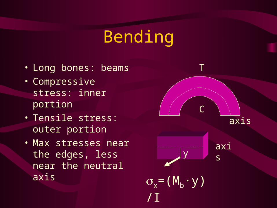
Bending
• Long bones: beams• Compressive stress:
inner portion• Tensile stress: outer
portion• Max stresses near the
edges, less near the neutral axis
C
T
axis
x=(Mb·y)/I
yaxis

Bending Moments
• Shear stresses max at neutral axis and zero at the surface
= (Q·V)/(I ·b)• Q= area moment• V= vertical shear force
h
b
Q
y

Bending
• Three point bending– failure at middle
– ski boot fracture
• Four point bending– failure at the weakest
point between two inside forces

Bending
• Cantilever bending• Compressive force
acting off-center from long axis

Torsion
• Twisting action applied to a structure
• Resistance about long axis determined by polar moment of inertia
• J=[·(r4o-r4
i)]/2
• Shear stress along the shaft =(T·r)/J
• Twist angle: =(T·l)/(G·J)

Torsion
• Larger radius of the shaft, greater resistance
• Stiffer the material harder to deform
• In addition to shear stress, normal stress (tensile & compressive) are produced in a helical path (spiral fractures)
r

Viscoelasticity
• Provided by the fluid component in biological tissue
• Resistance to flow• Affects stress-strain• Increase in strain rate
produces-increases stiffness of the material

Viscoelasticity
• Pure elastic material– strain energy returned
– no energy loss
• Viscoelastic tissues– lose energy due to heat
– energy is not returned immediately
– Resilient
– Dampened
• Hysteresis: area representing energy lost
Load
unlo
ad
Elastic
Non

Viscoelasticity
• Creep response• Stress-relaxation
response• Effects of strain-rate
on stress relaxation
Time
creep

Material Fatigue & Failure
• Fatigue: repeated loads above a certain threshold
• Continued loading: failure
• First cycle effect: shift in mechanical response
1 2 3 n
Initial cycle effect

Material failure
• Distribution of stresses– Discontinuity (stress risers)
• fractures sites
• screws
• osteotendinous junctions
• Ductile vs Brittle materials
• Failure theories– maximal normal stress
– maximal shear stress
– maximal energy distortion

Biomechanical Modeling & Simulation
• Model: representation of one or more of an object’s or system’s characteristics using mathematical equations
• Goal– improve understanding of a
system
• Simulation:process of using validated model

Biomechanical Modeling & Simulation
• Physical model: simulates actual conditions, crash test dummies
• Mathematical or computer model: conditions are represented using mathematical equations

Why use a model?
• Easy to duplicate • Easy to make change
in the system• Time • Economic factor

How to select a model?
• What questions is being posed?
– Type: molecular, tissue, organ etc.
– Deformable or rigid– finite or
continuoum– static, quasi static
or dynamic
– Linear or nonlinear– 2D or 3D– Determined or
stochastic– kinematics or
kinetics– inverse or direct

Model & Simulations
• Models are simplifications of actual situations
• Model and simulation are as good as the data use as input
• Stability of the model (range of values)

Finite-element modeling
• Structures are represented as simple blocks assembled to form complex geometrical structures
• Connected at poinst (nodes) forming a mathetical representation of the structure
• Forces are applied at the structure and stress and strain are predicted
• Complex and requires a great deal of computing power

Finite modeling

Rheological Models
• Study of deformation and flow of matter
• Use to model biological tissue
• Interrelate stress, strain, and strain rate
• Three types
– Linear spring
– dashpot
– frictional
• Linear spring
– elastic properties of tissue

Rheological Models
• Dashpot– loading response that is
strain rate dependent
– fluid viscosity (newtonian fluid)
= ·
• Frictional element• Combinations of
models
Strain rate