Embed Size (px)
Citation preview

Chapter 3 Field Investigation
3.1 OverviewThis chapter addresses subsurface investigation that includes drilling and excavation of test pits as part of a geotechnical field investigation. It is organized by activities and policies involved prior to, during, and after exploration. Also addressed, through appendices included with this chapter, are best management practices for erosion and spill prevention during geotechnical field investigations, as well as other potential impacts to the natural environment in the vicinity of the geotechnical investigation site (Appendices 3-C and 3-D), and the handling, and disposing of, contaminated and potentially contaminated materials/samples obtained during the geotechnical field investigation (Appendices 3-E and 3-F).
3.2 Activities and Policies – Before ExplorationA geotechnical field exploration plan should be formulated as described in Chapter 2. The geotechnical designer assigned to the project is responsible to coordinate with the Region or Washington State Ferries (WSF) Project Office (project Office) to prepare the way for the field exploration crews to implement the field exploration program. The geotechnical designer also functions as the primary liaison between the region or WSF and the Field Exploration Manager (FEM), to keep the FEM informed as the region or WSF completes the necessary preparations to begin implementation of the field exploration plan.
Specifically, the geotechnical designer should do the following before submitting the final field exploration request to the FEM:
1. Make sure senior Geotechnical Division management agrees with the proposed exploration plan (see Section 1.4).
2. Make sure that the project office has provided adequate site data to locate test holes and key project features on paper and in the field.
3. Make sure that the project office has asked for (preferably obtained) an environmental assessment of the site to determine whether or not there is potential to encounter hazardous subsurface materials. The geotechnical designer is responsible to have a basic knowledge of previous site use as well.
4. Make sure that the project office has asked for (preferably obtained) an archeological assessment of the site to determine if there is potential to encounter Native American or other artifacts.
5. Coordinate with the project office to make sure any right-of-entry’s needed are obtained for the proposed drilling.
6. Coordinate with the project office to make sure the necessary permits are obtained (especially with regard to wetlands and other environmentally sensitive areas).
7. Coordinate with the Field Exploration Supervisor (FES) who will be assigned to the project, and the project office, to conduct a joint field review to evaluate access and other issues related to setting up and finalizing the field exploration program.
WSDOT Geotechnical Design Manual M 46-03.11 Page 3-1 May 2015

8. Act as the liaison between the Field Exploration Manager (FEM) and the project office to make sure the FEM knows when all the tasks have been completed and to inform the FEM of the results so that the exploration program can be properly estimated.
Note that to obtain permits and right-of-entry, a preliminary field exploration plan will likely be needed by the region (or WSF) before the final exploration plan is completed and turned in. Therefore, the development of the field exploration plan may require a somewhat iterative process. Once enough field exploration plan details have been developed, the geotechnical designer should request that those who will be directly negotiating with local owners to obtain right-of entry (if needed) invite the FEM or FES to assist in those negotiations. This generally makes the negotiations go much smoother.
If the geotechnical designer recognizes, either through an environmental assessment or through general knowledge of the previous site use, that there is a potential to encounter hazardous materials during the geotechnical field exploration, it is important that the geotechnical designer make the FEM aware of this as soon as possible in the development of the exploration plan. This will enable the FEM to be prepared to meet the requirements as specified in Appendices 3-C and 3-D, as well as to initiate procedures provided in Appendices 3-E and 3-F. The potential to encounter hazardous subsurface materials can completely change the approach, cost, and scheduling for the site exploration activities.
A preliminary field exploration plan is also needed for use as the basis for conducting the joint field review mentioned above. This field review should be used to determine how each individual exploration site will be accessed, the type of drill equipment best suited for the site, areas for utility locates, required traffic control, and to identify any permit, right-of-entry, and environmental issues. Adjustments to the specific locations of exploration points can be made as needed during the field review to address the above issues.
During the field review, the FES will stake the borings if they have not already been located and if right-of-entry (if needed) has been obtained. The FES should also assess the traffic control needs for the exploration work at this time. The FES will coordinate directly with the Maintenance Office for traffic control. After staking borings, the FES is responsible for calling all utility locates a minimum of 48 hours prior to the start of explorations.
Once the final field exploration plan has been completed, the FEM will provide a cost estimate to the geotechnical designer to complete the field exploration plan. Once the expenditure for the field exploration has been authorized, the geotechnical designer must then notify the FEM to commence with the field exploration. Once the exploration plan has been executed, any subsequent requests to modify the plan should be provided in writing by the geotechnical designer to the FES. The FES will respond with an updated estimate and schedule for requested plan change.
If the geotechnical design is to be conducted by a geotechnical consultant, the WSDOT geotechnical designer who is overseeing the consultant task assignment or agreement is responsible to make sure that the consultant accomplishes the tasks described above and to assist in the coordination between the consultant and the
Field Investigation Chapter 3
Page 3-2 WSDOT Geotechnical Design Manual M 46-03.11 May 2015
FEM. If the consultant needs changes to the field exploration plan, the geotechnical designer is responsible to provide input to the FES or FEM as to the acceptability of the changes. The FES or FEM is not to act on the requested changes to the field exploration plan without input from the geotechnical designer.
While the geotechnical designer is responsible to coordinate between the project office and the FEM or FES regarding permits, the project office is ultimately responsible to perform or provide right-of-entry, hazardous materials assessment and archeological evaluation for the site, and to provide adequate site data to locate the exploration points for exploration plan development and for location in the field.
Currently, WSDOT has a five-year blanket Hydraulic Project Approval (HPA) for both marine and fresh waters statewide. Once again the FEM or FES should be involved early in the process to define all technical questions for each project. For all barge projects, the drilling shall be in compliance with the provisions described in the general HPA from the Washington Department of Fish and Wildlife (WDF&WL).
The FEM (or as delegated to a FES) will assign the project to a drill inspector(s) and a drill crew. The drill inspector will then initiate a meeting with the geotechnical designer to discuss the objectives and any particulars of the exploration plan. Either the FES or the drill inspector should notify the geotechnical designer of the anticipated start date of the requested work.
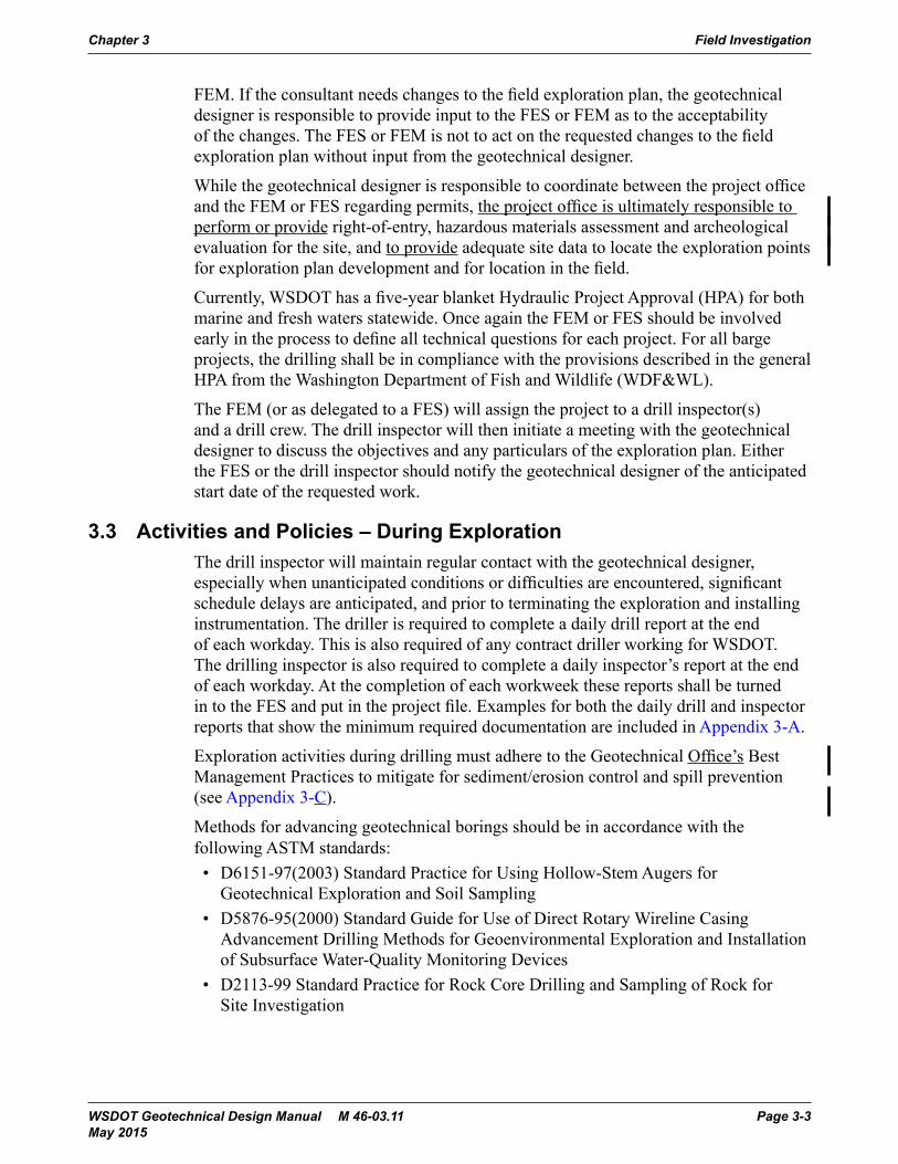
3.3 Activities and Policies – During ExplorationThe drill inspector will maintain regular contact with the geotechnical designer, especially when unanticipated conditions or difficulties are encountered, significant schedule delays are anticipated, and prior to terminating the exploration and installing instrumentation. The driller is required to complete a daily drill report at the end of each workday. This is also required of any contract driller working for WSDOT. The drilling inspector is also required to complete a daily inspector’s report at the end of each workday. At the completion of each workweek these reports shall be turned in to the FES and put in the project file. Examples for both the daily drill and inspector reports that show the minimum required documentation are included in Appendix 3-A.
Exploration activities during drilling must adhere to the Geotechnical Office’s Best Management Practices to mitigate for sediment/erosion control and spill prevention (see Appendix 3-C).
Methods for advancing geotechnical borings should be in accordance with the following ASTM standards:• D6151-97(2003) Standard Practice for Using Hollow-Stem Augers for
Geotechnical Exploration and Soil Sampling• D5876-95(2000) Standard Guide for Use of Direct Rotary Wireline Casing
Advancement Drilling Methods for Geoenvironmental Exploration and Installation of Subsurface Water-Quality Monitoring Devices
• D2113-99 Standard Practice for Rock Core Drilling and Sampling of Rock for Site Investigation
Chapter 3 Field Investigation
WSDOT Geotechnical Design Manual M 46-03.11 Page 3-3 May 2015

Hollow-stem augers are not to be used for assessment of liquefaction potential; wet rotary methods should be used. Further, care must be exercised during drilling with hollow-stem augers to mitigate for heave and loosening of saturated, liquefiable soils.
Sampling of subsurface materials should be in accordance with the following ASTM standards:• D1586-99 Standard Test Method for Penetration Test and Split-Barrel
Sampling of Soils• D3550-01 Standard Practice for Thick Wall, Ring-Lined, Split Barrel, Drive
Sampling of Soils• D1587-00 Standard Practice for Thin-Walled Tube Sampling of Soils for
Geotechnical Purposes• D4823-95(2003)e1 Standard Guide for Core Sampling Submerged,
Unconsolidated Sediments
In addition to the methods described above for sampling for soft, fine-grained sediments, WSDOT utilizes a thick-walled sampler referred to as the Washington undisturbed sampler. This sampler is lined with 2-inch (I.D.) extrudible brass tubes. The sampler is intended for stiffer fine-grained deposits than what would be suitable for Shelby tubes.
Down-the-hole hammers are not allowed for use in performing Standard Penetration Tests.
Samples should be handled in accordance with the following ASTM standards:• D4220-95(2000) Standard Practices for Preserving and Transporting Soil Samples• D5079-02 Standard Practices for Preserving and Transporting Rock Core Samples
Disturbed soil samples should be placed in watertight plastic bags. For moisture-critical geotechnical issues, a portion of the sample should be placed in a moisture tin and sealed with tape. Extreme care must be exercised when handling and transporting undisturbed samples of soft/loose soil; undisturbed samples must also be kept from freezing. Rock cores of soft/weak rock should be wrapped in plastic to preserve in situ moisture conditions. Rock cores should be placed in core boxes from highest to lowest elevation and from left to right. Coring intervals should be clearly labeled and separated. Core breaks made to fit the core in the box must be clearly marked on the core. All soil and rock samples should be removed from the drill site at the end each day of drilling and transported to the laboratory as soon as possible.
In situ testing methods commonly employed in geotechnical investigations should be in accordance with the following ASTM standards:• D2573-01 Standard Test Method for Field Vane Shear Test in Cohesive Soil• D5778-95(2000) Standard Test Method for Performing Electronic Friction Cone
and Piezocone Penetration Testing of Soils
Field Investigation Chapter 3
Page 3-4 WSDOT Geotechnical Design Manual M 46-03.11 May 2015
Groundwater monitoring and in situ characterization methods commonly employed in geotechnical investigations should be in accordance with the following ASTM standards:• D5092-02 Standard Practice for Design and Installation of Ground Water
Monitoring Wells in Aquifers• D4750-87(2001) Standard Test Method for Determining Subsurface Liquid Levels
in a Borehole or Monitoring Well (Observation Well)• D4044-96(2002) Standard Test Method for (Field Procedure) for Instantaneous
Change in Head (Slug) Tests for Determining Hydraulic Properties of Aquifers
Additional information on ground water investigation and monitoring is provided in Mayne, et al. (2002).
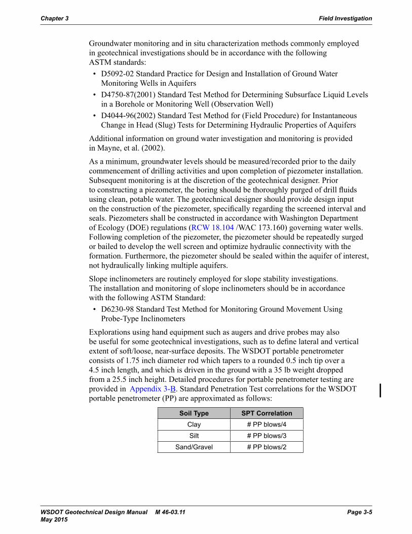
As a minimum, groundwater levels should be measured/recorded prior to the daily commencement of drilling activities and upon completion of piezometer installation. Subsequent monitoring is at the discretion of the geotechnical designer. Prior to constructing a piezometer, the boring should be thoroughly purged of drill fluids using clean, potable water. The geotechnical designer should provide design input on the construction of the piezometer, specifically regarding the screened interval and seals. Piezometers shall be constructed in accordance with Washington Department of Ecology (DOE) regulations (RCW 18.104 /WAC 173.160) governing water wells. Following completion of the piezometer, the piezometer should be repeatedly surged or bailed to develop the well screen and optimize hydraulic connectivity with the formation. Furthermore, the piezometer should be sealed within the aquifer of interest, not hydraulically linking multiple aquifers.
Slope inclinometers are routinely employed for slope stability investigations. The installation and monitoring of slope inclinometers should be in accordance with the following ASTM Standard:• D6230-98 Standard Test Method for Monitoring Ground Movement Using
Probe-Type Inclinometers
Explorations using hand equipment such as augers and drive probes may also be useful for some geotechnical investigations, such as to define lateral and vertical extent of soft/loose, near-surface deposits. The WSDOT portable penetrometer consists of 1.75 inch diameter rod which tapers to a rounded 0.5 inch tip over a 4.5 inch length, and which is driven in the ground with a 35 lb weight dropped from a 25.5 inch height. Detailed procedures for portable penetrometer testing are provided in Appendix 3-B. Standard Penetration Test correlations for the WSDOT portable penetrometer (PP) are approximated as follows:
Soil Type SPT CorrelationClay # PP blows/4
Silt # PP blows/3
Sand/Gravel # PP blows/2
Chapter 3 Field Investigation
WSDOT Geotechnical Design Manual M 46-03.11 Page 3-5 May 2015
The excavation of test pits can provide valuable subsurface information not determinable or well characterized by test borings. Extreme care should be exercised around open excavations, and access within them should adhere to Washington Administrative Code (WAC) sections 296-155-655 and 296-155-657.Prior to de-mobilizing, the drill inspector should ensure location information (e.g., station, offset, elevation and/or state plane coordinates) of all the explorations are recorded on the field logs. If exact location information is unavailable upon completion of field activities, a sketch of each exploration location should be made indicating relationship to observable features (i.e., bridge/structure, mile post, etc.). This information should be provided with the field logs to the geotechnical designer. In addition to providing field logs for all explorations, required documentation for test pits should include a scale drawing of the excavation and photographs of the excavated faces. Sampling methods and in situ measurement devices such as pocket penetrometers should also be documented. Detailed requirements for boring logs are provided in Chapter 4.
3.4 Activities and Policies – After ExplorationUpon completion of subsurface explorations, a finished log for each exploration is to be sent to the Department of Ecology (DOE) by the FES. In addition to subsurface conditions encountered, the log must include location (address, county, and ¼ - ¼ Section/Township/Range) and installation information (well #, type of instrumentation, seals, and screened interval).
Unless otherwise requested by the geotechnical designer, all explorations and resource protection wells (piezometers and inclinometers) shall be properly decommissioned prior to construction as per DOE requirements (WAC 173-160-381,500 and RCW 18.104.048). The construction Project Engineer is responsible for notifying the FEM at least 72 hours prior to required time for decommissioning.
Upon completion, the drilling inspector shall transmit recovered samples to the State Materials Lab and provide both the original copy of the field notes and a finished log for all explorations to the geotechnical designer. If the samples to be transmitted to the lab are known to be contaminated or are potentially contaminated, the procedures provided in Appendices 3-E and 3-F shall be followed.
3.5 Standard Penetration Test (SPT) CalibrationCalibration to determine specific hammer system efficiencies shall be developed in general accordance with ASTM D4633 for dynamic analysis of driven piles or other accepted procedure. Measured hammer efficiencies for WSDOT drilling equipment are summarized at a link found at the following web address: www.wsdot.wa.gov/biz/mats/Geotech/default.htm.
3.6 ReferencesMayne, P. W., Christopher, B.R., and DeJong, J., 2002, Subsurface Investigations – Geotechnical Site Characterization, Publication No. FHWA NHI-01-031, National Highway Institute, Federal Highway Administration, Washington, DC, 300 pp.
Field Investigation Chapter 3
Page 3-6 WSDOT Geotechnical Design Manual M 46-03.11 May 2015

Appendix 3-A Daily Drill Report Form
Daily Drill ReportSR
DOT Form 350-152 EFRevised 7/2007
CS
Project
Date
Project No.
Drill Drill No.
Structure Line Landslide Materials SourceHole No Size Angle From To Soil Rock Total
Item Hours Item HoursMobilization and DemobilizationOn Site Moving/RiggingDrill Site PreparationSoil DrillingRock DrillingReaming HolePlacing and Removing CasingHole StabilizationInstall and Maintain Water SystemWater Delay
Water Haul: MileageEquipment DowntimeExplain:Standby for Hole Survey and Other DelaysExplain:Installation of InstrumentationType:Special TestingType:Travel Time
ExpendablesCore Boxes Piezo Pipe Slope Incl Cement Bentonite Additives
Other
Support Equipment No. Job Yard O Serv.
Remarks
Inspector
Reg. OT Comp Total
Driller
Helper
Shift Start Shift Finish Service Codes
WSDOT Geotechnical Design Manual M 46-03.10 Page 3-A-1 August 2014

Daily Drill Report Form Appendix 3-A
Page 3-A-2 WSDOT Geotechnical Design Manual M 46-03.10 August 2014

Appendix 3-B Portable Penetrometer Test Procedures
Background
The WSDOT portable penetrometer (PP) is a field test used in highway and small foundation design. The test may be used in both cohesive (clay) and cohesionless (sands & gravels) soils. The test values (i.e., blow count per foot of penetration) are dependent upon the effective overburden pressure of granular soils and shear strength of cohesionless soils. However, since all equations and correlations related to use of blow count values are approximate, sound engineering judgment is necessary for accurate interpretation of the test results.
The PP test is a derivative of the Standard Penetration Test (SPT), the most widely used method for determining soil conditions in the world. The SPT is both a dynamic penetration test and a method of obtaining disturbed samples. For the SPT test, a split-spoon sampler attached to drill steel is driven downward by the impact of a falling weight on the steel. In the SPT test, a 140 lb. weight falls a distance of 30 inches per blow. In the PP test method, a 35 lb weight falls an approximate distance of 25.5 inches. In the SPT test, as a split-spoon sampler is driven downward, it fills with disturbed soil. In the PP test, no sample is obtained as a solid, cone-shaped tip is driven downward by a falling weight. However, the PP method requires excavation of a test hole, and samples should be obtained with each change in soil strata.
Equipment
Performance of portable penetrometer testing requires two groups of equipment. The first group is associated with preparation of a drilled borehole, backhoe test pit, or hand-excavated test hole. This group includes the tools used to dig the hole, with a hand auger employed most frequently in a PP test application. A list of equipment used for excavation of a test hole with a hand auger follows:• Shovel with pointed end for breaking up turf and vegetation at the surface.• Posthole digger for assistance in establishing the test hole excavated using the
hand auger.• Hand auger to include: auger, pipe extensions (± 3 feet lengths), and handle.• Steel bar to loosen up hard pack soil and assist in the removal of rock or gravel
from the test hole.• Tarp for collecting representative samples of soil strata.• Field notebook and pencil for recording location of test holes, numbers and
descriptions of distinct soil layers encountered, and other information relative to a review of site characteristics and conditions.
• Sample bags with ties for preservation of samples of material encountered with changes of soil strata.
• Marker for writing on sample bags or tags to delineate test hole and depth of sample collection.
• Pocket or rag tape to be used to locate the test hole relative to some reference point, grid, or proposed alignment and for measurement of depth below surface of distinct soil strata and depth of exploration.
WSDOT Geotechnical Design Manual M 46-03.10 Page 3-B-1 August 2014

The PP device and accessories form the second group of equipment required for geotechnical investigation of proposed highway or small foundation designs. A list of the equipment necessary for this group follows:• Portable penetrometer to include cone-shaped tip; drill rod sections (A-rod -
1.75 in. pipe OD & 22.5 in. lengths); falling weight section (length of bar for sliding weight up and down); the 35-lb weight; and the coupling devices used for connecting the tip – drill rod sections – falling weight section – falling weight stop.
• Pipe wrenches (2) used to loosen connections when breaking down the portable penetrometer.
• Lathe or another “straight-edge” useful for establishing a surface reference elevation.
• Construction crayon or marker used for marking three 6 inch intervals on the penetrometer in order to clearly delineate displacement as the penetrometer is driven into the ground.
• Rags to wipe down equipment, removing moisture and dirt, prior to packing away equipment.
Test Procedure
1. Using a shovel or other hand tool, strip away sod or surface vegetation and set aside for future restoration of the location. Using a posthole digger or a 6 in diameter or greater hand auger, dig down approximately 2 feet, noting the depth of topsoil, subsoil, and other changes in soil strata. Describe soil conditions such as color, texture, and moisture content of the soils encountered in the bore log. Collect samples for lab soil classification, grain size determination, or Atterberg limits determination.
2. Assemble the PP device for evaluation of soils near the surface. Use threaded coupling devices to connect the cone-shaped tip, drill rod sections, and falling weight slide section.
3. Measure the distance from the bottom of the test hole to the surface and record. From the tip of the penetrometer, measure this distance on the body of the testing device and annotate a reference line on the body of the device. From this line measure and mark three intervals, each 6 inches in length.
4. Lift up the PP device and place the tip at the bottom of the test hole. Insure that the bottom or base line mark lines up with the approximate ground surface. Place a lathe or other straight edge on the ground surface so that any downward displacement of the PP device may be measured accurately.
5. Lift the 35 lb weight up and lower it down on to the upper, slide portion of the testing device. Screw on the threaded stop at the upper end of the slide section.
Portable Penetrometer Test Procedures Appendix 3-B
Page 3-B-2 WSDOT Geotechnical Design Manual M 46-03.10 August 2014

6. Performance of PP testing requires a minimum of two people. One person should be responsible for steadying the PP device in the test hole, counting the number of times the weight drops, and watching the reference line in order to stop the process every time the device is displaced downward a total of 6 inches. The second person is responsible for raising and dropping the weight in as smooth and controlled manner as possible. Raising the weight upward of fifty times per 6 inch interval can prove to be a workout. Additional personnel can be employed to relieve the person responsible for lifting the weight and assist in the manual work requirements of test hole excavation.
7. For each “blow”, the 35 lb weight drops a distance of approximately 25.5 in. The number of blows required to drive the cone penetrometer through three 6 inch intervals is recorded. The count for the initial 6 inch interval is noted but isn’t used to compute a test value because it reflects the seating of the PP device. The sum of the blows for the last two 6 inch intervals is recorded. This sum of the blows represents the blow count for that 1 foot interval below the surface.
8. Upon completion of PP testing at a specific depth, the device is unseated by thrusting the weight against the stop at the end of the slide. Repeating this action should loosen the tip and permit removal of the device from the test hole.
9. Employ the hand auger to remove material “disturbed” by the action of the PP. Place this affected material on the tarp and obtain a sample for lab testing. Associate PP test results with material sampled from the proper test hole and elevation.
10. Continue advancing the auger into the soil, emptying soil and repeating the procedure until the desired depth is reached. Advances from one PP test to the next lower level test are usually in 2 feet increments. Monitor the condition and properties of the soil, noting any changes in strata. Obtain samples as necessary.
11. To prepare the PP device for the next test at a lower test hole level, remove the weight stop, 35 1b weight, and slide section to permit the attachment of additional drill rod sections. Re-attach the slide section to the penetrometer. Measure the distance from the bottom of the test hole to the surface. Mark this distance on the body of the testing device by measuring from the tip and annotating a base line corresponding to the distance on the PP device.
12. With assistance, lift the PP into the test hole, properly seat it in the center of the hole, and insure that the base line corresponds with the ground surface.
13. Lift the weight up and onto the slide section and screw in the threaded stop at the top end of the slide.
14. Perform PP test procedure and sampling as described previously.
15. Monitor changes in soil strata as the hand auger advances downward in the test hole. In general, sample only when there are obvious changes in soil strata. Use engineering judgment to guide whether additional sampling and testing are warranted. As the degree of geologic complexity increases, the degree of sampling and testing increases as well.
Appendix 3-B Portable Penetrometer Test Procedures
WSDOT Geotechnical Design Manual M 46-03.10 Page 3-B-3 August 2014

Figures 3-C-1 through 3-C-8 illustrate the equipment and procedures used for conducting the Portable Penetrometer test.
Figure 3C-1. Perform a field reconnaissance of the site of the geotechnical investigation.Insure that the proposed design is tied to an established coordinate system, datum, or permanent monument.
Figure 3C-2. Hand augers used in conjunction with the PP test.
WSDOT Geotechnical Design Manual June 2006 Page 3-C-4
Perform a field reconnaissance of the site of the geotechnical investigation. Insure that the proposed design is tied to an established coordinate system, datum, or permanent monument.
Figure 3-C-1
Figure 3C-1. Perform a field reconnaissance of the site of the geotechnical investigation.Insure that the proposed design is tied to an established coordinate system, datum, or permanent monument.
Figure 3C-2. Hand augers used in conjunction with the PP test.
WSDOT Geotechnical Design Manual June 2006 Page 3-C-4
Hand augers used in conjunction with the PP test.
Figure 3-C-2
Portable Penetrometer Test Procedures Appendix 3-B
Page 3-B-4 WSDOT Geotechnical Design Manual M 46-03.10 August 2014
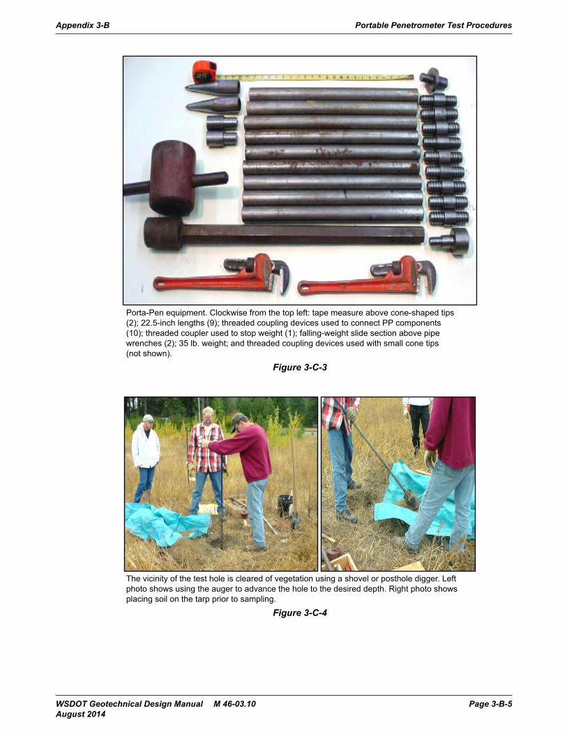
Figure 3C-3. Porta-Pen equipment. Clockwise from the top left: tape measure above cone-shaped tips (2); 22.5-inch lengths (9); threaded coupling devices used to connect PP components (10); threaded coupler used to stop weight (1); falling-weight slide section above pipe wrenches (2); 35 lb. weight; and threaded coupling devices used with small cone tips (not shown).
Figure 3C-4. The vicinity of the test hole is cleared of vegetation using a shovel or posthole digger. Left photo shows using the auger to advance the hole to the desired depth . Right photo shows placing soil on the tarp prior to sampling.
WSDOT Geotechnical Design Manual June 2006 Page 3-C-5
Porta-Pen equipment. Clockwise from the top left: tape measure above cone-shaped tips (2); 22.5-inch lengths (9); threaded coupling devices used to connect PP components (10); threaded coupler used to stop weight (1); falling-weight slide section above pipe wrenches (2); 35 lb. weight; and threaded coupling devices used with small cone tips (not shown).
Figure 3-C-3
Figure 3C-3. Porta-Pen equipment. Clockwise from the top left: tape measure above cone-shaped tips (2); 22.5-inch lengths (9); threaded coupling devices used to connect PP components (10); threaded coupler used to stop weight (1); falling-weight slide section above pipe wrenches (2); 35 lb. weight; and threaded coupling devices used with small cone tips (not shown).
Figure 3C-4. The vicinity of the test hole is cleared of vegetation using a shovel or posthole digger. Left photo shows using the auger to advance the hole to the desired depth . Right photo shows placing soil on the tarp prior to sampling.
WSDOT Geotechnical Design Manual June 2006 Page 3-C-5
The vicinity of the test hole is cleared of vegetation using a shovel or posthole digger. Left photo shows using the auger to advance the hole to the desired depth. Right photo shows placing soil on the tarp prior to sampling.
Figure 3-C-4
Appendix 3-B Portable Penetrometer Test Procedures
WSDOT Geotechnical Design Manual M 46-03.10 Page 3-B-5 August 2014

Figure 3C-5. Photo of PP device in the process of being assembled. The threaded coupling devices on the left side of the box are used to connect the cone-shaped tip to lengths forming the body of the penetrometer. The lengths forming the body of the penetrometer are then connected to the section on which the weight slides.
Figure 3C-6. Marking a base line on the body of the penetrometer. This will line up with the top of the test hole. In addition, also mark three 6 inch intervals, measured from this base line, to track the downward displacement when the falling weight is applied.
WSDOT Geotechnical Design Manual June 2006 Page 3-C-6
Photo of PP device in the process of being assembled. The threaded coupling devices on the left side of the box are used to connect the cone-shaped tip to lengths forming the body of the penetrometer. The lengths forming the body of the penetrometer are then connected to the section on which the weight slides.
Figure 3-C-5
Figure 3C-5. Photo of PP device in the process of being assembled. The threaded coupling devices on the left side of the box are used to connect the cone-shaped tip to lengths forming the body of the penetrometer. The lengths forming the body of the penetrometer are then connected to the section on which the weight slides.
Figure 3C-6. Marking a base line on the body of the penetrometer. This will line up with the top of the test hole. In addition, also mark three 6 inch intervals, measured from this base line, to track the downward displacement when the falling weight is applied.
WSDOT Geotechnical Design Manual June 2006 Page 3-C-6
Marking a base line on the body of the penetrometer. This will line up with the top of the test hole. In addition, also mark three 6 inch intervals, measured from this base line, to track the downward displacement when the falling weight is applied.
Figure 3-C-6
Portable Penetrometer Test Procedures Appendix 3-B
Page 3-B-6 WSDOT Geotechnical Design Manual M 46-03.10 August 2014
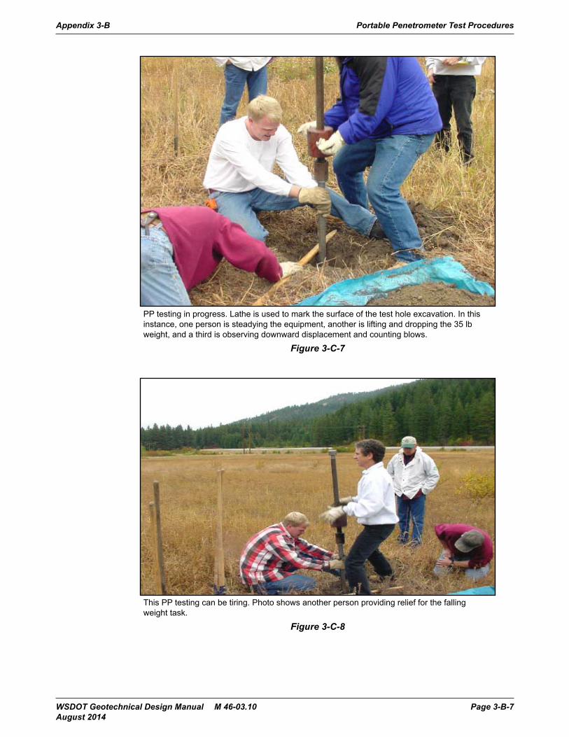
Figure 3C-7. PP testing in progress. Lathe is used to mark the surface of the test hole excavation. In this instance, one person is steadying the equipment, another is lifting and dropping the 35 lb weight, and a third is observing downward displacement and counting blows.
Figure 3C-8. This PP testing can be tiring. Photo shows another person providing relief for the falling weight task.
WSDOT Geotechnical Design Manual June 2006 Page 3-C-7
PP testing in progress. Lathe is used to mark the surface of the test hole excavation. In this instance, one person is steadying the equipment, another is lifting and dropping the 35 lb weight, and a third is observing downward displacement and counting blows.
Figure 3-C-7
Figure 3C-7. PP testing in progress. Lathe is used to mark the surface of the test hole excavation. In this instance, one person is steadying the equipment, another is lifting and dropping the 35 lb weight, and a third is observing downward displacement and counting blows.
Figure 3C-8. This PP testing can be tiring. Photo shows another person providing relief for the falling weight task.
WSDOT Geotechnical Design Manual June 2006 Page 3-C-7
This PP testing can be tiring. Photo shows another person providing relief for the falling weight task.
Figure 3-C-8
Appendix 3-B Portable Penetrometer Test Procedures
WSDOT Geotechnical Design Manual M 46-03.10 Page 3-B-7 August 2014

Portable Penetrometer Test Procedures Appendix 3-B
Page 3-B-8 WSDOT Geotechnical Design Manual M 46-03.10 August 2014

Field Investigation Best Management Practices for Appendix 3-C Erosion and Spill Prevention
The Washington State Department of Transportation (WSDOT) is dedicated to protecting the environment when conducting field exploration projects. This memo outlines the erosion/sediment control and spill prevention best management practices (BMPs) that will be followed for all drilling activities.
The two distinct scenarios for drilling include pavement and vegetated areas. The variety of erosion and sediment control BMPs may vary between the two scenarios, but the philosophy of minimizing site disturbance, reducing waste materials, trapping sediment, and stabilizing the site, remains the same.
Disturbance Minimizing BMPs:• Select the smallest rig capable for the job• Use elevated scaffolding for driller and assistant when necessary
Waste Reduction BMPs:• Re-circulate drilling slurry• Minimize volume of water for drilling
Sediment Trapping BMPs:• Baffled mud tub (sealed with bentonite to prevent fluid loss)• Polyacrylamide (PAM) for flocculation (must meet ANSI/NSF Standard 60)• Silt fence (trenched, below drill, and on contour)• Sand bag barrier (washed gravel, below drill, two rows high, and on contour)• Straw bale barrier (trenched, staked, below drill, and on contour)• Catch basin insert (pre-fabricated type, above or below grate)• Storage of slurry in locked drums
Site Stabilization BMPs:• Seed with pasture grass• Straw mulch (2” maximum for seeded areas)
All BMPs will be installed and a thorough inspection for sensitive areas (wetlands, streams, aquifer recharge, etc.) and stormwater conveyances will be conducted, prior to starting drilling activities. At no time shall drilling slurry or cuttings be allowed to enter Water Bodies of the State of Washington.
When sensitive resources or conveyances to these areas exist, all slurry and cuttings will be stored in lockable drums and disposed of off-site. If not, the slurry will slowly be infiltrated into the ground using surrounding vegetated areas and the cuttings will be stored and disposed of off-site.
Removal of sediment control BMPs will be performed immediately after drilling is completed. Place trapped sediment with cuttings in drums. If significant soil disturbance occurs during drilling, the BMPs will be left in place until the site is stabilized with grass or mulch.
WSDOT Geotechnical Design Manual M 46-03.10 Page 3-C-1 August 2014

The drill crew will have a copy of the Hydraulic Project Approval (HPA), issued by the Washington State Department of Fish and Wildlife (WDFW) on-site for all work adjacent to or over water. The Supervisor will discuss the requirements of this permit with the crew prior to each project. All of the provisions in each HPA will be strictly followed until the completion of said project. The previously defined erosion/sediment control philosophy and BMPs will be implemented in these conditions
The approach to protecting surface and ground water is focused on prevention. The drill shaft will be filled with bentonite clay to prevent mixing of aquifers and eliminating the route for surface contaminants. In addition, the following Spill Prevention Control & Countermeasures (SPCC) BMPs will be used when applicable:
Minimize Risk:• Visually inspect equipment for leaks or worn hoses on a daily basis• Fix equipment leaks as soon as possible to minimize cleanup• Use proper equipment to transfer materials• Reduce the overall volume of fuel and chemicals on site• Remove as many sources of spills as possible from the site when not working
(evenings/weekends)• Use environmentally-friendly chemicals whenever possible• Store all chemicals with lids closed and keep containers under cover• Have secondary containment devices underneath potential spill sources when
applicable (e.g. 5 gallon bucket)
Maximize Response:• Each drilling operation will have at least one emergency spill response kit on site
at all times• Know who to call in case of emergency spill
If an incidental spill (less than 1 gallon/small equipment leak) occurs, immediately collect contaminated soil and store it in label storage drum. Do not mix soils with different contaminants together. Report spill to your supervisor, as they are aware of reporting requirements.
If a major spill (more than 1 gallon) to water occurs, control the source of the leak if possible and contact the Washington State Emergency Management Division (800-258-5990) and the National Response Center (800-424-8802). If a major spill to soil occurs and there is immediate risk to human health and/or the environment, control the source of the leak if possible and contact the Washington State Department of Ecology (800-407-7170). Then contact your supervisor, as they are aware of reporting requirements.
Field Investigation Best Management Practices for Erosion and Spill Prevention Appendix 3-C
Page 3-C-2 WSDOT Geotechnical Design Manual M 46-03.10 August 2014

Department of Natural Resources Memorandum of Understanding: Drilling Appendix 3-D Operations – State Owned Aquatic Lands
WSDOT Geotechnical Design Manual M 46-03.10 Page 3-D-1 August 2014

Page 3-D-2 WSDOT Geotechnical Design Manual M 46-03.10 August 2014
Department of Natural Resources Appendix 3-D Memorandum of Understanding: Drilling Operations – State Owned Aquatic Lands

WSDOT Geotechnical Design Manual M 46-03.10 Page 3-D-3 August 2014
Department of Natural Resources Memorandum of Understanding: Drilling Operations – State Owned Aquatic Lands Appendix 3-D

Page 3-D-4 WSDOT Geotechnical Design Manual M 46-03.10 August 2014
Department of Natural Resources Appendix 3-D Memorandum of Understanding: Drilling Operations – State Owned Aquatic Lands
WSDOT Geotechnical Design Manual M 46-03.10 Page 3-D-5 August 2014
Department of Natural Resources Memorandum of Understanding: Drilling Operations – State Owned Aquatic Lands Appendix 3-D

Page 3-D-6 WSDOT Geotechnical Design Manual M 46-03.10 August 2014
Department of Natural Resources Appendix 3-D Memorandum of Understanding: Drilling Operations – State Owned Aquatic Lands

Geotechnical Field Investigation and Contaminated Drilling Appendix 3-E Waste Management Procedures
Requirements for handling, storage, and disposal of hazardous materials encountered during geotechnical drilling are provided at the following website: www.wsdot.wa.gov/Environment/HazMat/Investigations.htm#Geotech
WSDOT Geotechnical Design Manual M 46-03.11 Page 3-E-1 May 2015

Geotechnical Field Investigation and Contaminated Drilling Waste Management Procedures Appendix 3-E
Page 3-E-2 WSDOT Geotechnical Design Manual M 46-03.11 May 2015

State Materials Laboratory Sample- Handling Policy for Contaminated Appendix 3-F and Potentially Contaminated Samples
On a project level, if any contaminated sites are brought to the attention of the Geotechnical Project Manager (GPM), he/she shall immediately notify and forward all contaminant information to the Structural Materials Testing Engineer (SMTE) of the State Materials Laboratory (SML) and the Field Exploration Manager (FEM). Similarly, if the FEM, FE Supervisor, or FE crew is made aware of or suspects the presence of contaminants on a project, they shall immediately notify the GPM and the SMTE. This information shall include the project number, project name, location, boring (if applicable), and the types and scale of the contamination.
The SMTE shall pass this information to the SML geotechnical lab employees. Three situations are anticipated with regard to contaminated or potentially contaminated samples. The sample handling and disposal protocol applicable to the situation shall be followed. These situations, and the protocols associated with those situations, are described in the sections that follow.
Situation 1: Contaminated Soils Encountered in the Field Soils (or rock) encountered in the field known or suspected to be contaminated shall not be submitted to the lab for standard sample processing and testing. In the event suspected or known contaminated soils/rock are encountered in the field, the following protocol shall be followed:
1. The FE crew shall immediately stop drilling/sampling operations and call the FEM, Supervisor and GPM for direction.
2. The FEM and/or GPM shall then contact the Environmental Services Office (ESO) for direction.
3. Utilizing appropriate PPE, any samples suspected or known to be contaminated shall be marked as contaminated and placed in the contaminated holding area or drum, as directed by the ESO. Labeling should be in the form of a single (~4”) strip of black and yellow striped tape and be placed on all samples (across the baggie, or over the cap of a Shelby tube). All drill cuttings and fluids from the boring shall also be placed in sealed drums. All samples from a suspected contaminated boring should be kept together until they have been cleared for testing.
4. If the ESO determines that a suitable secure and offsite storage area is not available or not necessary, they may direct the suspected/known contaminated materials to be transported to the SML for disposal characterization. The FEM or GPM shall then notify the SMTE that suspected/known contaminated samples are being transported to the SML.
WSDOT Geotechnical Design Manual M 46-03.11 Page 3-F-1 May 2015
State Materials Laboratory Sample-Handling Policy for Contaminated and Potentially Contaminated Samples Appendix 3-F
5. The FEM shall establish a secure area outside of the main SML building, where the FE crew shall place the samples while they await disposal characterization by the ESO. The FEM shall then notify the ESO of the receipt of samples and request their direction on disposition.
6. Once analytical test results have been obtained, the ESO will direct the soil/rock samples and cuttings to be disposed of properly (protocols for what this entails shall be provided by the ESO) or make them available for geotechnical testing if contamination test(s) indicate they are suitable for geotechnical testing.
7. The samples shall not have geotechnical testing performed on them without being cleared to be tested by the ESO and Safety Office. The ESO/Safety Office shall determine the appropriate safety level for any subsequent testing/handling to be performed by SML employees. It is understood that at this time, only soils/rock not exceeding regulatory cleanup levels, and that have been cleared by the ESO Office, shall be suitable for geotechnical testing to be performed at the SML. Samples not cleared for testing at the SML should not enter the building.
8. Samples cleared for geotechnical testing by the ESO/Safety Office shall be labelled with additional green tape prior to delivery to the SML, indicating that the samples have been cleared for testing but extra precaution should be used. The black and yellow tape shall remain on the samples.
Situation 2: Screened Samples - Known Contaminants Exist in a Boring, but Samples are Screened in the Field and Deemed Safe for Geotechnical Testing
1. All samples from a contaminated boring should be kept together until they have been cleared for testing.
2. Upon direction from the ESO, samples that have been retained at a secure offsite location and confirmed to not exceed regulatory cleanup levels through analytical testing may be transmitted to the SML for geotechnical testing. Prior to transmitting the samples to the SML for geotechnical testing, the ESO shall notify the FEM, who in turn will notify the GPM and SMTE, that the soil samples are marginally contaminated and that they may be safely processed for geotechnical testing using appropriate PPE.
3. All such contaminated samples shall be properly labeled before being taken to the SML.
4. Labeling should be in the form of a single (~4”) strip of green tape placed on all samples (across the baggie, core box, or over the cap of a Shelby tube), indicating that the sample has been cleared for testing but extra precaution should be used.
5. All lab employees handling such marked samples shall use proper PPE and be at a heightened awareness for the possibility of contaminants to exist in these samples.
6. PPE for marginally contaminated materials includes latex/rubber gloves, eye protection, and other equipment or handling methods as deemed necessary by the ESO (which will vary based on the types of contaminants encountered).
7. Once cleared samples have been tested by the SML Soils Lab, at the direction of the GPM they may be disposed of in the same manner as non-contaminated soils.
Page 3-F-2 WSDOT Geotechnical Design Manual M 46-03.11 May 2015
Appendix 3-F State Materials Laboratory Sample-Handling Policy for Contaminated and Potentially Contaminated Samples
Situation 3: Unexpected Contaminated Samples Discovered in the SML
If samples inadvertently make it to the SML that are suspected by lab personnel to be contaminated, lab personnel shall immediately secure all samples from the entire boring in an airtight container, label the container as having suspected contaminated samples, and notify the SMTE and the FEM, who shall then contact the ESO for direction.
If any tests have been performed on a sample and contamination is suspected after the fact, the SMTE and FEM should be notified immediately to determine how to proceed. Any equipment that came into contact with the contaminated sample should be identified and addressed (segregated, cleaned) according to ESO recommendations.
Detailing proper disposal for samples determined by ESO to be contaminated and not suitable for geotechnical testing is deemed outside the scope of this protocol. The ESO will convey the disposal requirements to the FEM or, in his absence, the FE Supervisors, and the FE personnel shall follow those disposal procedures accordingly.
WSDOT Geotechnical Design Manual M 46-03.11 Page 3-F-3 May 2015

State Materials Laboratory Sample-Handling Policy for Contaminated and Potentially Contaminated Samples Appendix 3-F
Page 3-F-4 WSDOT Geotechnical Design Manual M 46-03.11 May 2015