Embed Size (px)
Citation preview

7/29/2019 Chapter 3 Electromagnetic
http://slidepdf.com/reader/full/chapter-3-electromagnetic 1/26

7/29/2019 Chapter 3 Electromagnetic
http://slidepdf.com/reader/full/chapter-3-electromagnetic 2/26
Chapter 3 Electromagnetic
2 Physics Department SMK Sultan Ismail
3.1 ANALYSING THE MAGNETIC EFFECT OF CURRENT-CARRYING CONDUCTOR
ELECTROMAGNETS1. Electromagnetism is the study of the relationship between electricity and
magnetism.2. A bar magnet produces the magnetic fields around it. Draw the pattern of the
magnetic fields produced around a bar magnet below
Magnetic fields of a bar magnet
3. An electromagnet is a temporary magnet.4. A simple electromagnet consists of a solenoid with a soft iron core inside.5. Soft iron is used because it has the following characteristics;
(a) Easily magnetised when the current in the solenoid is switched on.(b) Loses all its magnetism when the current is switched off.
6. If the soft iron is replaced with a steel core, the steel core becomes apermanent magnet when current flows in the solenoid.
7. Figure 1 shows the action of an electromagnet.
N S

7/29/2019 Chapter 3 Electromagnetic
http://slidepdf.com/reader/full/chapter-3-electromagnetic 3/26
Chapter 3 Electromagnetic
3 Physics Department SMK Sultan Ismail
Figure 1
8. Using the diagram above, complete the steps to switch on the magnetism
effect.
9. The electromagnet uses the magnetic effect of an electric current. A current-carrying wire produces a magnetic field in the region around the wire.
THE MAGNETIC FIELD DUE TO A CURRENT IN A STRAIGHT WIRE
Figure 2
Switch isclosed
Current
flows
Magnetic
filed
Soft iron
core is
magnetised
Attracts
pins

7/29/2019 Chapter 3 Electromagnetic
http://slidepdf.com/reader/full/chapter-3-electromagnetic 4/26
Chapter 3 Electromagnetic
4 Physics Department SMK Sultan Ismail
1. The magnetic field lines are concentric circles as shown in figure 2.2. The direction of magnetic field can be determined using “right-hand grip rule”.
- Thumb pointing in the direction of the current.- The other four fingers show the direction of the magnetic field round the
wire.
Diagram above shows the symbols of direction of currents out of or into a
paper.
THE MAGNETIC FIELD DUE TO A CURRENT IN A COIL
1. Figure 3 shows the magnetic field produced by a current in circular coil.2. The magnetic lines are closest to each other at the centre of the coil with the
magnetic field at the centre is the strongest.
The magnetic field pattern by the current in the circular coil

7/29/2019 Chapter 3 Electromagnetic
http://slidepdf.com/reader/full/chapter-3-electromagnetic 5/26
Chapter 3 Electromagnetic
5 Physics Department SMK Sultan Ismail
3. The strength of the magnetic field increases when,(a) the current is increased(b) the coil has more number of turns(c) a coil of smaller radius is used
THE MAGNETIC FIELD DUE TO A CURRENT IN A SOLENOID
Figure 4
1. The magnetic field for a solenoid has a similar pattern to the magnetic field ofa bar magnet as shown in figure 4.
2. One end of the solenoid is a North Pole (N) while the other end is a South Pole(S).
3. The polarity at the ends of the solenoid can be determined by;
Right-hand grip rule

7/29/2019 Chapter 3 Electromagnetic
http://slidepdf.com/reader/full/chapter-3-electromagnetic 6/26
Chapter 3 Electromagnetic
6 Physics Department SMK Sultan Ismail
Looking at the ends of the solenoid.
A clockwise indicates a South Pole while
an anti-clockwise indicates a North Pole.
USE OF ELECTROMAGNETS
Electric Bell
Figure 5
1. In an electric bell, the electromagnet is switched on and off very rapidly bymaking and breaking contact.
2. When you press the switch, current flows in the coil, creating an electromagnet.3. The electromagnet then attracts the hammer towards the gong to hit it.4. When the hammer moves towards the gong, the contact opens. The circuit is
broken and the current stops flowing.5. The coil loses its magnetism and the hammer returns to its original position,
completing the circuit again.6. In this way, the hammer hits and lifts off from the gong repeatedly, making the
bell ring as long as the switch is on.

7/29/2019 Chapter 3 Electromagnetic
http://slidepdf.com/reader/full/chapter-3-electromagnetic 7/26
Chapter 3 Electromagnetic
7 Physics Department SMK Sultan Ismail
ELECTROMAGNETIC RELAY
Figure 6
1. In circuit 1 when the switch is closed, current flows and the iron rocker arm isattracted to the electromagnet and pushes the contacts together. Circuit 2 isnow switched on.
2. Circuit 2 may have a large current flowing through it to operate powerful
motors or very bright lights. When the switch is opened, the electromagnetreleases the rocker arm and the spring moves the contact apart. Circuit 2 isnow switched off.
3. The advantage of using a relay is that a small current (circuit 1) can be used toswitch on and off a circuit with a large current (circuit 2).
7/29/2019 Chapter 3 Electromagnetic
http://slidepdf.com/reader/full/chapter-3-electromagnetic 8/26
Chapter 3 Electromagnetic
8 Physics Department SMK Sultan Ismail
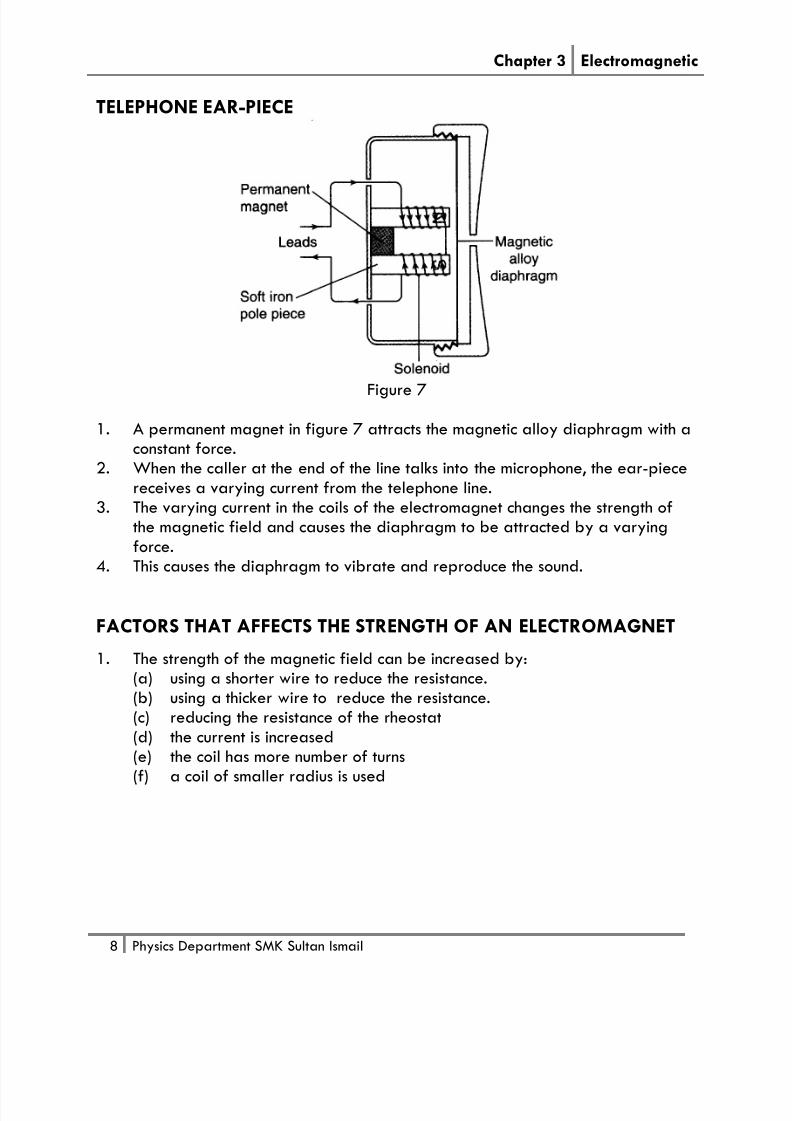
TELEPHONE EAR-PIECE
Figure 7
1. A permanent magnet in figure 7 attracts the magnetic alloy diaphragm with aconstant force.
2. When the caller at the end of the line talks into the microphone, the ear-piecereceives a varying current from the telephone line.
3. The varying current in the coils of the electromagnet changes the strength ofthe magnetic field and causes the diaphragm to be attracted by a varyingforce.
4. This causes the diaphragm to vibrate and reproduce the sound.
FACTORS THAT AFFECTS THE STRENGTH OF AN ELECTROMAGNET
1. The strength of the magnetic field can be increased by:(a) using a shorter wire to reduce the resistance.(b) using a thicker wire to reduce the resistance.(c) reducing the resistance of the rheostat(d) the current is increased(e) the coil has more number of turns(f) a coil of smaller radius is used

7/29/2019 Chapter 3 Electromagnetic
http://slidepdf.com/reader/full/chapter-3-electromagnetic 9/26
Chapter 3 Electromagnetic
9 Physics Department SMK Sultan Ismail
3.1 THE FORCE ON A CURRENT-CARRYING CONDUCTOR IN AMAGNETIC FIELD
1. Electrical motors are found in many household items such as the fan, blender
and hairdryer.2. The rotation is due to forces that are produced by using a current and amagnetic field.
Magnetic field around a wire Magnetic field between twomagnadur magnet
The force experienced by a current-carrying wire in a magnetic field.
Figure 6
3. When a current carrying conductor is placed in the magnetic field of apermanent magnet as shown in figure 6, the interaction between the twomagnetic fields (magnetic field of the permanent magnet and magnetic fieldproduced by the current-carrying conductor) produced a force on theconductor.
4. This produced a resultant field known as a catapult field as shown in figure 7.
7/29/2019 Chapter 3 Electromagnetic
http://slidepdf.com/reader/full/chapter-3-electromagnetic 10/26
Chapter 3 Electromagnetic
10 Physics Department SMK Sultan Ismail
+
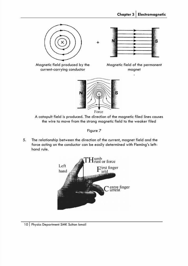
Magnetic field produced by thecurrent-carrying conductor
Magnetic field of the permanentmagnet
.
A catapult field is produced. The direction of the magnetic filed lines causesthe wire to move from the strong magnetic field to the weaker filed
Figure 7
5. The relationship between the direction of the current, magnet field and theforce acting on the conductor can be easily determined with Fleming’s left-hand rule.

7/29/2019 Chapter 3 Electromagnetic
http://slidepdf.com/reader/full/chapter-3-electromagnetic 11/26
Chapter 3 Electromagnetic
11 Physics Department SMK Sultan Ismail
CoilN
S
B
A2
3
4
1
current
C
D
Carbon
brush
commutator
Magnet
6. The direction of the force on the conductor is perpendicular to the direction ofthe current and the direction of the magnetic field.
THE TURNING EFFECT OF A CURRENT-CARRYING COIL IN AMAGNETIC FIELD
1. Consider a current-carrying coil ABCD placed between the poles magnet asshown in the figure below.
2. As the current flows through the coil from A to D, an upward (1) force acts onthe arm CD whereas a downward (3) force acts on the arms AB according toFleming’s Left Hand rule.
3. The interaction between the magnetic field of the current and the magneticfield of the permanent magnet produced a resultant magnetic field as shown infigure 7.
Electrical energy Kinetic energy

7/29/2019 Chapter 3 Electromagnetic
http://slidepdf.com/reader/full/chapter-3-electromagnetic 12/26
Chapter 3 Electromagnetic
12 Physics Department SMK Sultan Ismail
Figure 7
4. The two forces which are in opposite directions constitute a couple whichproduces a turning effect and the coil rotates in a clockwise.
AMMETER
Figure 9
1. Figure 9 shows the internal parts of the ammeter or voltmeter.2. When a current passes through the coil, equal and opposite parallel forces act
respectively on the sides of the coil beside the poles of the permanent magnet.3. This pair of forces causes the coil to rotate until it is stopped by the control
springs.4. When there is no current flow, the forces no longer exist. The control springs
bring the coil back to its original position and the pointer goes back to zerodeflection.

7/29/2019 Chapter 3 Electromagnetic
http://slidepdf.com/reader/full/chapter-3-electromagnetic 13/26
Chapter 3 Electromagnetic
13 Physics Department SMK Sultan Ismail
DIRECT CURRENT MOTOR
1. The direct current motor (d.c motor) uses the turning effect on a current-carrying coil in a magnetic field.
2. A d.c motor consists of a rectangular coil of wire placed between two
permanent magnets.3. Both ends of the coil are soldered to a commutator made of two semicircularcopper rings.
4. The use of a commutator is to enable a smooth change of direction of thecurrent flow in the coil continuously rotates in one direction every half turn ofthe coil.
5. Two carbon brushes are held against the commutator with a slight pressurewith the aid of spring.
6. The current flows from the brush P to the coil and out of the coil via the brushQ.

7/29/2019 Chapter 3 Electromagnetic
http://slidepdf.com/reader/full/chapter-3-electromagnetic 14/26
Chapter 3 Electromagnetic
14 Physics Department SMK Sultan Ismail
Stage 1 Stage 2
Horizontal position
- Switch is closed, current flows in thedirection abcd.
- The force on the side ab isdownwards
- The force on the side cd is upwards.- These two forces produce a couple
which rotates the coil in clockwisedirection.
Vertical/Upright position
- The contact between the carbonbrushes P and Q with thecommutator X and Y is broken.
- No current flows in the coil thereforeno turning force.
Stage 3 Stage 4
Horizontal position
- Carbon brush P touches Y and carbonbrush Q touches X.
Vertical/upright position
- The contact between the carbon

7/29/2019 Chapter 3 Electromagnetic
http://slidepdf.com/reader/full/chapter-3-electromagnetic 15/26
Chapter 3 Electromagnetic
15 Physics Department SMK Sultan Ismail
- The current flows in the directiondcba.
- The force on the side ab is upwardswhile the force on the side cd isdownwards.
brushes P and Q with thecommutator X and Y is broken.
- No current flows in the coil thereforeno turning force.
- The above process are repeatedand the motor continues to rotateuntil the current is cut off.
FACTORS THAT AFFECT THE SPEED OF ROTATION OF AN ELECTRICMOTOR
1. The magnitude of force acting on a conductor in a magnetic increases by:
(a) increasing the current(b) using a stronger magnet(c) increasing the number of turns on the coil.
8.2 ANALYSING ELECTROMAGNETIC INDUCTION
1. The production of an electric current by a changing magnetic field is calledelectromagnetic induction.
2. The induced current is produced when,
(a) a conductor cuts across a magnetic flux(b) a change of magnetic flux linkage with a coil

7/29/2019 Chapter 3 Electromagnetic
http://slidepdf.com/reader/full/chapter-3-electromagnetic 16/26
Chapter 3 Electromagnetic
16 Physics Department SMK Sultan Ismail
3. From the observations of the above activities, it is found that the movement ofthe magnet or the copper wire produces an induce current in the wire. Theexistence of the induced current is detected by the galvanometer.
4. The direction of the induced current can be determined using Fleming’s right-hand rule.
Fleming’s right-hand rule
INDUCED E.M.F BY COIL
Magnetic fieldlines are beingcut.Current induced
No deflection onthe galvanometerNo current isinduced
Current induced inopposite direction
Moving the coiltowards a magnet alsoinduces current

7/29/2019 Chapter 3 Electromagnetic
http://slidepdf.com/reader/full/chapter-3-electromagnetic 17/26
Chapter 3 Electromagnetic
17 Physics Department SMK Sultan Ismail
1. In the above activities, an induced current is produced when there is relativemotion between the bar magnet and the solenoid.
2. The induced current produced in this case is due to the change of magnetic flux
linkage with the solenoid.
FARADAY’S LAW1. Faraday’s law state that the magnitude of the induced e.m.f. is directly
proportional to the rate of change of magnetic flux experience by theconductor.
2. The magnitude of the induced current or e.m.f increases with(a) the relative motion between the magnet and the coil is increased(b) the number of turns on the coil is increased(c) the cross-sectional area of the coil is increased
(d) a stronger magnet is used
LENZ’S LAW1. Lenz’s law is used to determine the polarity of the ends of the solenoid.2. Fleming’s right hand grip rule is then used to determine the direction of the
induced current in the solenoid.3. Lenz’s Law states that the direction of the induced e.m.f is such that its
magnetic effects always oppose the change producing.
4. Lanz’s law is an example of the Principle of Conservation of Energy. When themagnet or solenoid is moved against the opposing force, work is done.Therefore mechanical energy is converted to electrical energy.

7/29/2019 Chapter 3 Electromagnetic
http://slidepdf.com/reader/full/chapter-3-electromagnetic 18/26
Chapter 3 Electromagnetic
18 Physics Department SMK Sultan Ismail
APPLICATION OF ELECTROMAGNETIC INDUCTION1. A generator is basically the inverse of a motor. A generator consists of many
coils of wire wound on an armature that can rotate in a magnetic field.2. The coil is rotated by an external force (e.g. falling water, steam, etc) so that
the coil cuts the magnetic field/flux lines as it rotates.
DC GENERATOR

7/29/2019 Chapter 3 Electromagnetic
http://slidepdf.com/reader/full/chapter-3-electromagnetic 19/26
Chapter 3 Electromagnetic
19 Physics Department SMK Sultan Ismail
Graph of output current from the dc generator
When coils is at its horizontal position900 and 2700. The Change of rates ofmagnetic flux is maximum and Inducede.m.f is maxsimum.
When coils is at its vertical position 00,1800 and 3600.No changes of magnetic flux and Noe.m.f is induced

7/29/2019 Chapter 3 Electromagnetic
http://slidepdf.com/reader/full/chapter-3-electromagnetic 20/26
Chapter 3 Electromagnetic
20 Physics Department SMK Sultan Ismail
AC GENERATOR1. Two slip rings are used to obtain an alternating current output.
2. When coils is at its horizontal position 900 and 2700. Change of rates ofmagnetic flux is maximum and Induced e.m.f is maxsimum.
3. When coils is at its vertical position 00, 1800 and 3600. No changes ofmagnetic flux and no e.m.f is induced.

7/29/2019 Chapter 3 Electromagnetic
http://slidepdf.com/reader/full/chapter-3-electromagnetic 21/26
Chapter 3 Electromagnetic
21 Physics Department SMK Sultan Ismail
ALTERNATING AND DIRECT CURRENT (a.c/d.c)
Aspect Direct Current (d.c) Alternating current (a.c)
Current-time
graph
Characteristics - Magnitude of current isconstant.
- Current flows in one directiononly.
- Magnitude of current ischange with time.
Effect on a
capacitor
The bulb does not light up
Note: The bulb light up for a veryshort while after the switch is
closed.
The bulb lights up
Note: Capacitor allows alternatingcurrent but not direct current to
pass through.
Effect on a bulb The bulb lights upNote: Both currents produce heating of the filament

7/29/2019 Chapter 3 Electromagnetic
http://slidepdf.com/reader/full/chapter-3-electromagnetic 22/26
Chapter 3 Electromagnetic
22 Physics Department SMK Sultan Ismail
3.4 ANALYSING TRANSFORMER
1. In Malaysia, our electricity for domestic supplied at a voltage of 240 V a.c.
2. However, most of home appliances at home use lower than or higer than240V.
3. A transformer is a device which used to rise or lower the potential differenceof an alternating current.
4. It works on the principles of electromagnetic induction.
OPERATING PRINCIPLE OF A TRANSFORMER
1. A simple transformer consists of two coils wound on a laminated iron core.
A transformer Symbol
2. The coil which is connected to the power supply whose voltage is to be raisedor lowered is called the primary coil.The supply voltage is called the primary (input) voltage, Vp.
3. The other coil which is connected to the electrical equipment or resistor is calledthe secondary coil.

7/29/2019 Chapter 3 Electromagnetic
http://slidepdf.com/reader/full/chapter-3-electromagnetic 23/26
Chapter 3 Electromagnetic
23 Physics Department SMK Sultan Ismail
The voltage across the secondary coil is called the secondary (output) voltage,Vs.
4. The operating principle of a transformer is based on electromagneticinduction.
5. When the alternating current in the primary coil flows, it produced a flux ormagnetic field lines.
6. The change of the magnetic flux in the primary coils causes the magnetic fluxto cut the secondary coil.
7. The changing of the magnetic flux produces an induced e.m.f across thesecondary coil with the same frequency as the electrical supply.Note: The primary coil must be connected to an a.c supply an not d.c supply. This
is because an induced e.m.f will not be produced in the secondary coil. The d.c is
constant does not create a changing magnetic flux in the secondary coil.
STEP-UP AND STEP-DOWN TRANSFORMERS
Step-down transformer Step-up transformer
The number of turns in the secondary coilis less than the number of turns in theprimary coil.
The number of turns in the secondary coilis greater than the number of turns in theprimary coil.
The voltage across the secondary coil isless than the voltage across the primarycoil.
The voltage across the secondary coil isgreater than the voltage across theprimary coil.
Ns < Np & Vs < Vp Ns > Np & Vs > Vp

7/29/2019 Chapter 3 Electromagnetic
http://slidepdf.com/reader/full/chapter-3-electromagnetic 24/26
Chapter 3 Electromagnetic
24 Physics Department SMK Sultan Ismail
p
s
p
s
N
N=
V
V
EFFICIENCY OF A TRANSFORMER
1. The efficiency of a transformer in normally less than 100% that is the power ofthe output is less than the power of the input.
2. A transformer transfers electrical energy from one circuit to another circuit byelectromagnetic induction. In the process, a fraction of the electrical energy islost as heat energy.
3. Formula for the efficiency of a transformer:
Efficiency = 100%xpowerInput
powerOutput
= 100%xP
P
i
o
IDEAL TRANSFORMER1. Ideal transformer is no loss of energy in a transformer, all the energy supplied
to the primary coil will be transferred to the secondary coil which has anefficiency of 100%.
∴ Output power = Input powerPo = Pi VsIs = VpIp
p
s
VV =
s
p
II

7/29/2019 Chapter 3 Electromagnetic
http://slidepdf.com/reader/full/chapter-3-electromagnetic 25/26
Chapter 3 Electromagnetic
25 Physics Department SMK Sultan Ismail
FACTORS THAT AFFECT THE EFFICIENCY OF A TRANSFORMER ANDWAYS TO IMPROVE THE EFFICIENCY OF A TRANSFORMER
Factor Ways to minimise energy losses
Resistance of coilEnergy is lost as heat energy in the coilbecause of the heating effect of currentflow in a conductor.
Thick copper wire is used to reduce theresistance of the coil.
Magnetisation and demagnetisation ofiron coreThe core is continually magnetised anddemagnetised by the changingmagnetic field.
Some energy is transformed into heat inthe core.This loss is called hysteresis.
Using soft iron core. Easily magnetisedand demagnetised.
Eddy currents in iron coreThe core is itself a conductor, so thechanging magnetic flux in the iron coreinduced currents in it.Eddy currents generate heat in the ironcore.
Using laminated (layered) iron core.
Leakage of magnetic fluxElectrical energy is lost when a fractionof the magnetic flux produced by theprimary coil does not link with thesecondary coil. As result, there is areduction in e.m.f induced in thesecondary coil.
The iron core should be a closed loop ofiron with the secondary coil wound overthe primary coil.

7/29/2019 Chapter 3 Electromagnetic
http://slidepdf.com/reader/full/chapter-3-electromagnetic 26/26
Chapter 3 Electromagnetic
Examples 1Transformer that has 2000 turns in its primary coil is used to operate a 12 V, 24 Wlamps from the 240 V mains, as shown in figure 1.If energy losses in transformer can be neglected and the lamps is operated at itsratings, find(a) the number of turns in the secondary coil(b) the current in the secondary coil,(c) the current in the primary coil.
Examples 2A transformer enables a 12 V lamp to be used with a 240 V mains supply. If thereare 600 turns on the primary coil, calculate(a) the number of turns in the secondary coil,(b) the secondary current if the primary current is 0.5 A.(Assume no energy loss)
Examples3A transformer connected to the 240 V mains has 1000 turns on the secondary coil.The efficiency of the transformer is 80% and it is used to light a 12 V, 48 W lamps.If the lamp lights up with normal brightness, calculate(a) the number of turns in the primary coil(b) the primary current