Embed Size (px)
Citation preview

3-1
IntroductionAirplanes operate in an environment that is unlike an automobile. Drivers tend to drive with a fairly narrow field of view and focus primarily on forward motion. Beginning pilots tend to practice the same. Flight instructors face the challenge of teaching beginning pilots about attitude awareness, which requires understanding the motions of flight. An airplane rotates in bank, pitch, and yaw while also moving horizontally, vertically, and laterally. The four fundamentals (straight-and-level flight, turns, climbs, and descents) are the principle maneuvers that control the airplane through the six motions of flight.
Basic Flight ManeuversChapter 3
3-2
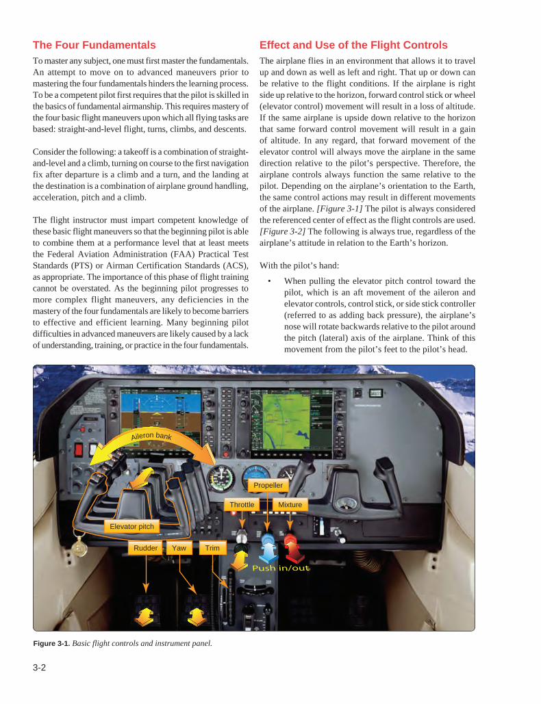
Figure 3-1. Basic flight controls and instrument panel.
Elevator pitch
Mixture
Propeller
TrimYawRudder
Throttle
Push in/out
Aileron bank
The Four FundamentalsTo master any subject, one must first master the fundamentals. An attempt to move on to advanced maneuvers prior to mastering the four fundamentals hinders the learning process. To be a competent pilot first requires that the pilot is skilled in the basics of fundamental airmanship. This requires mastery of the four basic flight maneuvers upon which all flying tasks are based: straight-and-level flight, turns, climbs, and descents.
Consider the following: a takeoff is a combination of straight-and-level and a climb, turning on course to the first navigation fix after departure is a climb and a turn, and the landing at the destination is a combination of airplane ground handling, acceleration, pitch and a climb.
The flight instructor must impart competent knowledge of these basic flight maneuvers so that the beginning pilot is able to combine them at a performance level that at least meets the Federal Aviation Administration (FAA) Practical Test Standards (PTS) or Airman Certification Standards (ACS), as appropriate. The importance of this phase of flight training cannot be overstated. As the beginning pilot progresses to more complex flight maneuvers, any deficiencies in the mastery of the four fundamentals are likely to become barriers to effective and efficient learning. Many beginning pilot difficulties in advanced maneuvers are likely caused by a lack of understanding, training, or practice in the four fundamentals.
Effect and Use of the Flight ControlsThe airplane flies in an environment that allows it to travel up and down as well as left and right. That up or down can be relative to the flight conditions. If the airplane is right side up relative to the horizon, forward control stick or wheel (elevator control) movement will result in a loss of altitude. If the same airplane is upside down relative to the horizon that same forward control movement will result in a gain of altitude. In any regard, that forward movement of the elevator control will always move the airplane in the same direction relative to the pilot’s perspective. Therefore, the airplane controls always function the same relative to the pilot. Depending on the airplane’s orientation to the Earth, the same control actions may result in different movements of the airplane. [Figure 3-1] The pilot is always considered the referenced center of effect as the flight controls are used. [Figure 3-2] The following is always true, regardless of the airplane’s attitude in relation to the Earth’s horizon.
With the pilot’s hand:
• When pulling the elevator pitch control toward the pilot, which is an aft movement of the aileron and elevator controls, control stick, or side stick controller (referred to as adding back pressure), the airplane’s nose will rotate backwards relative to the pilot around the pitch (lateral) axis of the airplane. Think of this movement from the pilot’s feet to the pilot’s head.

3-3
Figure 3-2. The pilot is always considered the referenced center of effect as the flight controls are used.
Lateral axis Aileron—Roll
Rudder—YawElevator—Pitch
Longitudinal axis
Vertical axis
Aileron Roll Longitudinal
Rudder Yaw Vertical
Elevator/stabilator Pitch Lateral
Primary control surface Airplane movement Axes of rotation
• When pushing the elevator pitch control toward the instrument panel, which is the forward movement of the aileron and elevator controls, control stick, or side stick controller (referred to as increasing forward pressure), the airplane rotates the nose forward relative to the pilot around the pitch axis of the airplane. Think of this movement from the pilot’s head to the pilot’s feet.
• When right pressure is applied to the aileron control, which is a clockwise rotation of aileron and elevator controls or the right deflection of the control stick or side stick controller, the airplane’s right wing banks (rolls) lower in relation to the pilot. Think of this movement from the pilot’s head to the pilot’s right hip.
• When left pressure is applied to the aileron control, which is a counterclockwise rotation of aileron and elevator controls or the left deflection of the control stick or side stick controller, the airplane’s left wing banks (rolls) lower in relation to the pilot. Think of this movement from the pilot’s head to the pilot’s left hip.
With the pilot’s feet:
• When forward pressure is applied to the right rudder pedal, the airplane’s nose moves (yaws) to the right in relation to the pilot. Think of this movement from the pilot’s left shoulder to the pilot’s right shoulder.
• When forward pressure is applied to the left rudder pedal, the airplane’s nose moves (yaws) to the left in
relation to the pilot. Think of this movement from the pilot’s right shoulder to the pilot’s left shoulder.
While in flight, the flight controls have a resistance to a pilot’s movement due to the airflow over the airplane’s control surfaces, and the control surfaces remain in a fixed position as long as all forces acting upon them remain balanced. The amount of force that the passing airflow exerts on a control surface is governed by the airspeed and the degree that the surface is moved out of its streamlined position. This resistance increases as airspeed increases and decreases as airspeed decreases. While the airflow over the control surfaces changes during various flight maneuvers, it is not the amount of control surface movement that is important. What is important, is that the pilot maneuvers the airplane by applying sufficient flight control pressures to obtain the desired result.
The pitch and roll flight controls (aileron and elevator controls, stick, or side-stick control) should be held lightly with the fingers and not grabbed or squeezed by the hand. When flight control pressure is applied to change a control surface position, pressure should only be exerted on the aileron and elevator controls with the fingers. This is an important concept and habit to learn which benefits the pilot as they progress to greater challenges such as instrument flying. A common error with beginning pilots is that they grab the aileron and elevator controls with a closed palm with such force that the sensitive feeling is lost. This must be avoided as it prevents the development of “feel,” which is an important aspect of airplane control.
The pilot’s feet should rest comfortably against the rudder pedals. Both heels should support the weight of the feet on the cockpit floor with the ball of each foot touching the individual rudder pedals. The legs and feet should be relaxed. When using the rudder pedals, pressure should be applied smoothly and evenly by pressing with the ball of one foot. Since the rudder pedals are interconnected through springs or a direct mechanical linkage and act in opposite directions, when pressure is applied to one rudder pedal, foot pressure on the opposite rudder pedal must be relaxed proportionately. Remember, the ball of each foot must rest comfortably on the rudder pedals so that even slight pressure changes can be felt.
In summary, during flight, it is pressure the pilot exerts on the aileron and elevator controls and rudder pedals that causes the airplane to move about the roll (longitudinal), pitch (lateral), and yaw (vertical) axes. When a control surface is moved out of its streamlined position (even slightly), the air flowing across the surface exerts a force against that surface and it tries to return it to its streamlined position. It is this force that the pilot feels as resistance on the aileron and elevator controls and the rudder pedals.

3-4
Figure 3-3. (A) Pitch attitude is the angle formed between the airplane’s longitudinal axis. (B) Bank attitude is the angle formed by the airplane’s lateral axis.
Pitch RollA B
Angle
Angle
Feel of the AirplaneThe ability to sense a flight condition, such as straight-and-level flight or a dive, without relying on cockpit instrumentation is often called “feeling the airplane.” Examples of this “feel” may be sounds of the airflow across the airframe, vibrations felt through the controls, engine and propeller sounds and vibrations at various flight attitudes, and the sensations felt by the pilot through physical accelerations.
Humans sense “feel” through kinesthesis (the ability to sense movement through the body) and proprioception (unconscious perception of movement and spatial orientation). These stimuli are detected by nerves and by the semicircular canals of the inner ear. When properly developed, kinesthesis can provide the pilot with critical information about changes in the airplane’s direction and speed of motion; however, there are limits in kinesthetic sense and when relied upon solely without visual information, as when flying in instrument meteorological conditions (IMC), ultimately leads to disorientation and loss of aircraft control.
Developing this “feel” takes time and exposure in a particular airplane and only comes with dedicated practice at the various flight conditions so that a pilot’s senses are trained by the sounds, vibrations, and forces produced by the airplane. The following are some important examples:
• Rushing air past a cockpit creates a distinctive noise pattern and as the level of sound increases, it likely indicates that the airplane’s airspeed is increasing and that the pitch attitude is decreasing. As the noise decreases, the airplane’s pitch attitude is likely increasing and its airspeed decreasing.
• The sound of the engine in cruise flight is different from that in a climb and different again when in a dive. In fixed-pitch propeller airplanes, when the airplane’s pitch attitude increases, the engine sound decreases and as pitch attitude decreases, the engine noise increases.
• In a banked turn, the pilot is forced downward into the seat due to the resultant load factor. The increased G force of a turn feels the same as the pull up from a dive, and the decreased G force from leveling out feels the same as lowering the nose out of a climb.
Sources of actual “feel” are very important to the pilot. This actual feel is the result of acceleration, which is simply how fast velocity is changing. Acceleration describes the rate of change in both the magnitude and the direction of velocity. These accelerations impart forces on the airplane and its occupants during flight. The pilot can sense these forces through pressures into or out of the seat; or shift the pilot from side to side in their seat as the airplane slips or skids. These forces need not be strong, only perceptible by the pilot to be useful. An accomplished pilot who has excellent “feel” for the airplane is able to detect even the smallest accelerations.
A flight instructor should direct the beginner pilot to be aware of these senses and teach an awareness of their meaning and their relationship to the various conditions of flight. To do this effectively, the flight instructor must fully understand the difference between perceiving and reacting to sound, vibrations, and forces versus merely noticing them. A pilot who develops a “feel” for the airplane early in flight training is likely to have less difficulty advancing in their flight training.
Attitude FlyingAn airplane’s attitude is determined by the angular difference between a specific airplane’s axis and the natural horizon. A false horizon can occur when the natural horizon is obscured or not readily apparent. This is an important concept because it requires the pilot to develop a pictorial sense of this natural horizon. Pitch attitude is the angle formed between the airplane’s longitudinal axis, which extends from the nose to the tail of the airplane, and the natural horizon. Bank attitude is the angle formed by the airplane’s lateral axis, which extends from wingtip to wingtip, and the natural horizon. [Figures 3-3A and 3-3B] Angular difference about

3-5
Figure 3-4. Airplane attitude is based on relative positions of the nose and wings on the natural horizon.
Bank control
Pitch control
the airplane’s vertical axis (yaw) is an attitude relative to the airplane’s direction of flight but not relative to the natural horizon.
Controlling an airplane requires one of two methods to determine the airplane’s attitude in reference to the horizon. When flying “visually” in visual meteorological conditions (VMC), a pilot uses their eyes and visually references the airplane’s wings and cowling to establish the airplane’s attitude to the natural horizon (a visible horizon). If no visible horizon can be seen due to whiteouts, haze over the ocean, night over a dark ocean, etc., it is IMC for practical and safety purposes. [Figure 3-4] When flying in IMC or when cross-checking the visual references, the airplane’s attitude is controlled by the pilot referencing the airplane’s mechanical or electronically generated instruments to determine the airplane’s attitude in relationship to the natural horizon.
Airplane attitude control is composed of four components: pitch control, bank (roll) control, power control, and trim.
• Pitch control—controlling of the airplane’s pitch attitude about the lateral axis by using the elevator to raise and lower the nose in relation to the natural horizon or to the airplane’s flight instrumentation.
• Bank control—controlling of the airplane about the airplane’s longitudinal axis by use of the ailerons to attain a desired bank angle in relation to the natural horizon or to the airplane’s instrumentation.
• Power control—in most general aviation (GA) airplanes is controlled by the throttle and is used when the flight situation requires a specific thrust setting or for a change in thrust to meet a specific objective.
• Trim control—used to relieve the control pressures held by the pilot on the flight controls after a desired attitude has been attained.
Note: Yaw control is used to cancel out the effects of yaw induced changes, such as adverse yaw and effects of the propeller.
Integrated Flight InstructionWhen introducing basic flight maneuvers to a beginning pilot, it is recommended that the “Integrated” or “Composite” method of flight instruction be used. This means the use of outside references and flight instruments to establish and maintain desired flight attitudes and airplane performance. [Figure 3-5] When beginning pilots use this technique, they achieve a more precise and competent overall piloting ability. Although this method of airplane control may become second nature with experience, the beginning pilot must make a determined effort to master the technique.
As the beginner pilot develops a competent skill in visual reference flying, the flight instructor should further develop the beginner pilot’s effectiveness through the use of integrated flight instruction; however, it is important that the beginner pilot’s visual skills be sufficiently developed for long-term, safe, and effective aircraft control. [Figure 3-5]
The basic elements of integrated flight instruction are as follows:
• The pilot visually controls the airplane’s attitude in reference outside to the natural horizon. At least 90 percent of the pilot’s attention should be devoted to outside visual references and scanning for airborne traffic. The process of visually evaluating pitch and bank attitude is nearly an imperceptible continuous stream of attitude information. If the attitude is found to be other than desired, the pilot should make precise, smooth, and accurate flight control corrections to return the airplane to the desired attitude. Continuous visual checks of the outside references and immediate corrections made by the pilot minimize the chance for the airplane to deviate from the desired heading, altitude, and flightpath.
• The airplane’s attitude is validated by referring to flight instruments and confirming performance. If the flight instruments display that the airplane’s performance is in need of correction, the required correction must be determined and then precisely,

3-6
Figure 3-5. Integrated flight instruction teaches pilots to use both external and cockpit attitude references.
OBS
N
E
S
W
333
24
21 15
12
30
6
NAV
GS
OBS
N
E
S
W
333
24
21 15
12
30
6
33
30
3N
XPDR 5537 IDNT LCL23:00:34
VOR 1
270°
2
1
1
2
3300
3200
3100
4000
2900
2800
2300
3000130
120
110
90
80
70TAS 100KT
NAV1 108.00 113.00NAV2 108.00 110.60
134.000 118.000 COM1123.800 118.000 COM2
WPT _ _ _ _ _ _ DIS _ _ ._ NM DTK _ _ _° TRK 360°
MAP - NAVIGATION MAP
ADF/DME MSG
D195I D212I
A212IHDG UP
10 NM
90 percent of the time, the pilot’s attention should be outside the flight deck.No more than 10 percent of the pilot’s attention should be inside the flight deck.
10%90%
60
20
1
9100 0003
smoothly, and accurately applied with reference to the natural horizon. The airplane’s attitude and performance are then rechecked by referring to flight instruments. The pilot then maintains the corrected attitude by reference to the natural horizon.
• The pilot should monitor the airplane’s performance by making quick snap-shots of the flight instruments. No more than 10 percent of the pilot’s attention should be inside the cockpit. The pilot must develop the skill to quickly focus on the appropriate flight instruments and then immediately return to the visual outside references to control the airplane’s attitude.
The pilot should become familiar with the relationship between outside visual references to the natural horizon and the corresponding flight instrument indications. For example, a pitch attitude adjustment may require a movement of the pilot’s reference point of several inches in relation to the natural horizon but correspond to a seemingly insignificant movement of the reference bar on the airplane’s attitude indicator. Similarly, a deviation from a desired bank angle, which is obvious when referencing the airplane’s wingtips or cowling relative to the natural horizon, may be imperceptible on the airplane’s attitude indicator to the beginner pilot.
The most common error made by the beginner pilot is to make pitch or bank corrections while still looking inside the cockpit. It is also common for beginner pilots to fixate on the flight instruments—a conscious effort is required by them to return to outside visual references. For the first several hours
of instruction, flight instructors may choose to use flight instrument covers to develop a beginning pilot’s skill or to correct a pilot’s poor habit of fixating on instruments by forcing them to use outside visual references for aircraft control.
The use of integrated flight instruction does not, and is not intended to prepare pilots for flight in instrument weather conditions. The most common error made by the beginning student is to make pitch or bank corrections while still looking inside the cockpit. Control pressure is applied, but the beginning pilot, not being familiar with the intricacies of flight by references to instruments, including such things as instrument lag and gyroscopic precession, will invariably make excessive attitude corrections and end up “chasing the instruments.” Airplane attitude by reference to the natural horizon, however, is immediate in its indications, accurate, and presented many times larger than any instrument could be. Also, the beginning pilot must be made aware that anytime, for whatever reason, airplane attitude by reference to the natural horizon cannot be established and/or maintained, the situation should be considered a bona fide emergency. Straight-and-Level FlightStraight-and-level flight is flight in which heading and altitude are constantly maintained. The four fundamentals are in essence a derivation of straight-and-level flight. As such, the need to form proper and effective skills in flying straight and level should not be understated. Precise mastery of straight-and-level flight is the result of repetition and effective practice. Perfection in straight-and-level flight comes only as a result of
3-7
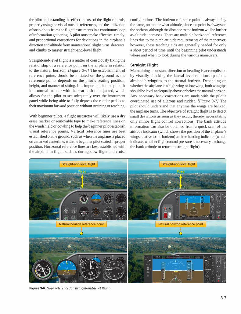
Figure 3-6. Nose reference for straight-and-level flight.
OBS
N
E
S
W
333
24
21 15
1230
6
NAV
GS
OBS
N
E
S
W
333
24
21 15
1230
6
33
3024
21 15
126
3
W
S
E
N
HDG
OBS
N
E
S
W
333
24
21 15
1230
6
NAV
GS
OBS
N
E
S
W
333
24
21 15
1230
6
33 3N
XPDR 5537 IDNT LCL 10:12:34
VOR 1
270°
2
1
1
2
4300
4200
4100
4000
3900
3800
4300
3600
3500
3400
3300
3200
3100
60
204000
4000130
120
110
90
80
70
11009
TAS 106KTOAT 7°C
ALERTS
NAV1 108.00 113.00NAV2 108.00 110.60
134.000 118.000 COM1123.800 118.000 COM2
WPT _ _ _ _ _ _ DIS _ _ ._ NM DTK _ _ _° TRK 360°
VOR 1
270°
2
1
1
2
4300
4200
4100
4000
3900
3800
2300
60
204000
4000130
120
110
90
80
70
11009
TAS 100KT
NAV1 108.00 113.00NAV2 108.00 110.60
134.000 118.000 COM1123.800 118.000 COM2
WPT _ _ _ _ _ _ DIS _ _ ._ NM DTK _ _ _° TRK 360°
MAP - NAVIGATION MAP
A212IHDG UP
Straight-and-level flight Straight-and-level flight
Fixed Fixed
Natural horizon reference pointNatural horizon reference point
the pilot understanding the effect and use of the flight controls, properly using the visual outside references, and the utilization of snap-shots from the flight instruments in a continuous loop of information gathering. A pilot must make effective, timely, and proportional corrections for deviations in the airplane’s direction and altitude from unintentional slight turns, descents, and climbs to master straight-and-level flight.
Straight-and-level flight is a matter of consciously fixing the relationship of a reference point on the airplane in relation to the natural horizon. [Figure 3-6] The establishment of reference points should be initiated on the ground as the reference points depends on the pilot’s seating position, height, and manner of sitting. It is important that the pilot sit in a normal manner with the seat position adjusted, which allows for the pilot to see adequately over the instrument panel while being able to fully depress the rudder pedals to their maximum forward position without straining or reaching.
With beginner pilots, a flight instructor will likely use a dry erase marker or removable tape to make reference lines on the windshield or cowling to help the beginner pilot establish visual reference points. Vertical reference lines are best established on the ground, such as when the airplane is placed on a marked centerline, with the beginner pilot seated in proper position. Horizontal reference lines are best established with the airplane in flight, such as during slow flight and cruise
configurations. The horizon reference point is always being the same, no matter what altitude, since the point is always on the horizon, although the distance to the horizon will be further as altitude increases. There are multiple horizontal reference lines due to the pitch attitude requirements of the maneuver; however, these teaching aids are generally needed for only a short period of time until the beginning pilot understands where and when to look during the various maneuvers.
Straight FlightMaintaining a constant direction or heading is accomplished by visually checking the lateral level relationship of the airplane’s wingtips to the natural horizon. Depending on whether the airplane is a high wing or low wing, both wingtips should be level and equally above or below the natural horizon. Any necessary bank corrections are made with the pilot’s coordinated use of ailerons and rudder. [Figure 3-7] The pilot should understand that anytime the wings are banked, the airplane turns. The objective of straight flight is to detect small deviations as soon as they occur, thereby necessitating only minor flight control corrections. The bank attitude information can also be obtained from a quick scan of the attitude indicator (which shows the position of the airplane’s wings relative to the horizon) and the heading indicator (which indicates whether flight control pressure is necessary to change the bank attitude to return to straight flight).

3-8
Figure 3-7. Wingtip reference for straight-and-level flight.
XPDR 5537 IDNT LCL23:00:34
VOR 1
270°
2
1
1
2
3300
3200
3100
4000
2900
2800
2300
60
203000
3000130
120
110
90
80
70
11009
TAS 100KT
NAV1 108.00 113.00NAV2 108.00 110.60
134.000 118.000 COM1123.800 118.000 COM2
WPT _ _ _ _ _ _ DIS _ _ ._ NM DTK _ _ _° TRK 360°
MAP - NAVIGATION MAP
ADF/DME MSG
D195I D212I
A212IHDG UP
10 NM
Left wingtip Right wingtip
It is possible to maintain straight flight by simply exerting the necessary pressure with the ailerons or rudder independently in the desired direction of correction. However, the practice of using the ailerons and rudder independently is not correct and makes precise control of the airplane difficult. The correct bank flight control movement requires the coordinated use of ailerons and rudder. Straight-and-level flight requires almost no application of flight control pressures if the airplane is properly trimmed and the air is smooth. For that reason, the pilot must not form the habit of unnecessarily moving the flight controls. The pilot must learn to recognize when corrections are necessary and then to make a measured flight control response precisely, smoothly, and accurately.
Pilots may tend to look out to one side continually, generally to the left due to the pilot’s left seat position and consequently focus attention in that direction. This not only gives a restricted angle from which the pilot is to observe but also causes the pilot to exert unconscious pressure on the flight controls in that direction. It is also important that the pilot not fixate in any one direction and continually scan outside the airplane, not only to ensure that the airplane’s attitude is correct, but also to ensure that the pilot is considering other factors for safe flight. Continually observing both wingtips has advantages other than being the only positive check for leveling the wings. This includes looking for aircraft traffic, terrain and weather influences, and maintaining overall situational awareness.
Level FlightIn learning to control the airplane in level flight, it is important that the pilot be taught to maintain a light touch on the flight controls using fingers rather than the common problem of a tight-fisted palm wrapped around the flight controls. The pilot should exert only enough pressure on the flight controls to produce the desired result. The pilot should learn to associate the apparent movement of the references with the control pressures which produce attitude movement. As a result, the pilot can develop the ability to adjust the change desired in the airplane’s attitude by the amount and direction of pressures applied to the flight controls without the pilot excessively referring to instrument or outside references for each minor correction.
The pitch attitude for level flight is first obtained by the pilot being properly seated, selecting a point toward the airplane’s nose as a reference, and then keeping that reference point in a fixed position relative to the natural horizon. [Figure 3-8] The principles of attitude flying require that the reference point to the natural horizon position should be cross-checked against the flight instruments to determine if the pitch attitude is correct. If not, such as trending away from the desired altitude, the pitch attitude should be readjusted in relation to the natural horizon and then the flight instruments cross-checked to determine if altitude is now being corrected or maintained. In level flight maneuvers, the terms “increase
3-9
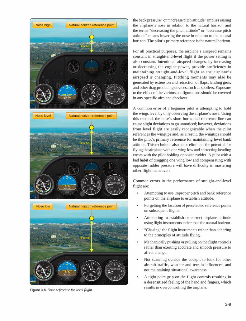
Figure 3-8. Nose reference for level flight.
OBS
N
S
W
33
24
21
30
NAV
OBS
N
S
W
33
24
21
30
33
3024
21
W
S
N
HDG
OBS
N
S
W
33
24
21
30
NAV
OBS
N
S
W
33
24
21
30
33
3024
21
W
S
N
HDG
OBS
N
S
W
33
24
21
30
NAV
N
W
33
30
Nose high
Nose level
Nose low
Natural horizon reference point
Natural horizon reference point
Natural horizon reference point
Fixed
Fixed
Fixed
the back pressure” or “increase pitch attitude” implies raising the airplane’s nose in relation to the natural horizon and the terms “decreasing the pitch attitude” or “decrease pitch attitude” means lowering the nose in relation to the natural horizon. The pilot’s primary reference is the natural horizon.
For all practical purposes, the airplane’s airspeed remains constant in straight-and-level flight if the power setting is also constant. Intentional airspeed changes, by increasing or decreasing the engine power, provide proficiency in maintaining straight-and-level flight as the airplane’s airspeed is changing. Pitching moments may also be generated by extension and retraction of flaps, landing gear, and other drag producing devices, such as spoilers. Exposure to the effect of the various configurations should be covered in any specific airplane checkout.
A common error of a beginner pilot is attempting to hold the wings level by only observing the airplane’s nose. Using this method, the nose’s short horizontal reference line can cause slight deviations to go unnoticed; however, deviations from level flight are easily recognizable when the pilot references the wingtips and, as a result, the wingtips should be the pilot’s primary reference for maintaining level bank attitude. This technique also helps eliminate the potential for flying the airplane with one wing low and correcting heading errors with the pilot holding opposite rudder. A pilot with a bad habit of dragging one wing low and compensating with opposite rudder pressure will have difficulty in mastering other flight maneuvers.
Common errors in the performance of straight-and-level flight are:
• Attempting to use improper pitch and bank reference points on the airplane to establish attitude.
• Forgetting the location of preselected reference points on subsequent flights.
• Attempting to establish or correct airplane attitude using flight instruments rather than the natural horizon.
• “Chasing” the flight instruments rather than adhering to the principles of attitude flying.
• Mechanically pushing or pulling on the flight controls rather than exerting accurate and smooth pressure to affect change.
• Not scanning outside the cockpit to look for other aircraft traffic, weather and terrain influences, and not maintaining situational awareness.
• A tight palm grip on the flight controls resulting in a desensitized feeling of the hand and fingers, which results in overcontrolling the airplane.

3-10
Figure 3-9. Elevator trim is used in airplanes to null the pressure exerted by the pilot on the pitch flight control.
Elevator trim wheel
Elevator trim indicator
• Habitually flying with one wing low or maintaining directional control using only the rudder control.
• Failure to make timely and measured control inputs when deviations from straight-and-level flight are detected.
• Inadequate attention to sensory inputs in developing feel for the airplane.
Trim ControlProper trim technique is an important and often overlooked basic flying skill. An improperly trimmed airplane requires constant flight control pressures from the pilot, produces tension and fatigue, distracts the pilot from outside visual scanning, and contributes to abrupt and erratic airplane attitude control inputs.
Trim control surfaces are required to offset any constant flight control pressure inputs provided by the pilot. For example, elevator trim is a typical trim in light GA airplanes and is used to null the pressure exerted by the pilot on the pitch flight control, which is being held to produce the tail down force required for a specific angle of attack (AOA). [Figure 3-9] This relieves the pilot from holding a constant pressure on the flight controls to maintain a particular pitch attitude and provides an opportunity for the pilot to divert attention to other tasks, such as evaluating the airplane’s attitude in relation to the natural horizon, scanning for aircraft traffic, and maintaining situational awareness.
Because of their relatively low power, speed, and cost constraints, not all light airplanes have a complete set (elevator, rudder, and aileron) trim controls that are adjustable from inside the cockpit. Nearly all light airplanes are equipped with at least a cockpit adjustable elevator trim. As airplanes increase in power, weight, and complexity, cockpit adjustable trim systems for the rudder and aileron may be available.
In airplanes where multiple trim axes are available, the rudder should be trimmed first. Rudder, elevator and then aileron should be trimmed next in sequence; however, if the airspeed is varying, continuous attempts to trim the rudder and aileron produces unnecessary pilot workload and distraction. Attempts to trim the rudder at varying airspeeds are impractical in many propeller airplanes because of the built-in compensation for the effect of a propeller’s left turning tendencies. The correct procedure is when the pilot has established a constant airspeed and pitch attitude, the pilot should then hold the wings level with aileron flight control pressure while rudder control pressure is trimmed out. Finally, aileron trim should then be adjusted to relieve any aileron flight control pressure.
A properly trimmed airplane is an indication of good piloting skills. Any control forces that the pilot feels should be a result of deliberate flight control pressure inputs during a planned change in airplane attitude, not a result of forces being applied by the airplane. A common trim control error is the tendency for the pilot to overcontrol the airplane with trim adjustments. Attempting to fly the airplane with the trim is a common fault in basic flying technique even among experienced pilots. The airplane attitude must be established first and held with the appropriate flight control pressures, and then the flight control pressures trimmed out so that the airplane maintains the desired attitude without the pilot exerting flight control pressure.
Level TurnsA turn is initiated by banking the wings in the desired direction of the turn through the pilot’s use of the aileron flight controls. Left aileron flight control pressure causes the left wing to lower in relation to the pilot. Right aileron flight control pressure causes the right wing to lower in relation to the pilot. In other words, to turn left, lower left wing with

3-11
Figure 3-10. Level turn to the left.
OBS
N
S
W
33
24
21
30
NAV
OBS
N
S
W
33
24
21
30
33
3024
21
W
S
N
HDG
XPDR 5537 IDNT LCL23:00:34
VOR 1
270°
2
1
1
2
3300
3200
3100
4000
2900
2800
2300
60
203000
3000130
120
110
90
80
70
11009
TAS 100KT
NAV1 108.00 113.00NAV2 108.00 110.60
134.000 118.000 COM1123.800 118.000 COM2
WPT _ _ _ _ _ _ DIS _ _ ._ NM DTK _ _ _° TRK 360°
MAP - NAVIGATION MAP
ADF/DME MSG
D195I D212I
A212IHDG UP
10 NM
aileron by left stick. To turn right, lower right wing with right stick. Depending on bank angle and airplane engineering, at many bank angles, the airplane will continue to turn with ailerons neutralized. So the sequence should be like the following: (1) bank airplane, adding either enough power or pitching up to compensate for the loss of lift (change in vector angle of lift); (2) neutralize controls as necessary to stop bank from increasing and hold desired bank angle; (3) use the opposite stick (aileron) to return airplane to level; (4) then take that control out to again neutralize the ailerons (along with either power or pitch reduction) for level flight. [Figure 3-10]
A turn is the result of the following:
• The ailerons bank the wings and so determine the rate of turn for a given airspeed. Lift is divided into both vertical and horizontal lift components as a result of the bank. The horizontal component of lift moves the airplane toward the banked direction.
• The elevator pitches the nose of the airplane up or down in relation to the pilot and perpendicular to the wings. If the pilot does not add power, and there is sufficient airspeed margin, the pilot must slightly increase the pitch to increase wing lift enough to replace the wing lift being diverted into turning force so as to maintain the current altitude.
• The vertical fin on an airplane does not produce lift. Rather the vertical fin on an airplane is a stabilizing surface and produces no lift if the airplane is flying
straight ahead. The vertical fin’s purpose is to keep the aft end of the airplane behind the front end.
• The throttle provides thrust which may be used for airspeed to tighten the turn.
• The pilot uses the rudder to offset any adverse yaw developed by wing’s differential lift and the engine/propeller. The rudder does not turn the airplane. The rudder is used to maintain coordinated flight.
For purposes of this discussion, turns are divided into three classes: shallow, medium, and steep.
• Shallow turns—bank angle is approximately 20° or less. This shallow bank is such that the inherent lateral stability of the airplane slowly levels the wings unless aileron pressure in the desired direction of bank is held by the pilot to maintain the bank angle.
• Medium turns—result from a degree of bank between approximately 20° to 45°. At medium bank angles, the airplane’s inherent lateral stability does not return the wings to level flight. As a result, the airplane tends to remain at a constant bank angle without any flight control pressure held by the pilot. The pilot neutralizes the aileron flight control pressure to maintain the bank.
• Steep turns—result from a degree of bank of approximately 45° or more. The airplane continues in the direction of the bank even with neutral flight controls unless the pilot provides opposite flight control aileron pressure to prevent the airplane from overbanking. The amount of opposite flight control pressures is dependent on various factors, such as bank angle and airspeed. In general, a noticeable level of opposite aileron flight control pressure is required by the pilot to prevent overbanking.
When an airplane is flying straight and level, the total lift is acting perpendicular to the wings and to the Earth. As the airplane is banked into a turn, total lift is the resultant of two components: vertical and horizontal. [Figure 3-11] The vertical lift component continues to act perpendicular to the Earth and opposes gravity. The horizontal lift component acts parallel to the Earth’s surface opposing centrifugal force. These two lift components act at right angles to each other, causing the resultant total lifting force to act perpendicular to the banked wing of the airplane. It is the horizontal lift component that begins to turn the airplane and not the rudder.
In constant altitude, constant airspeed turns, it is necessary to increase the AOA of the wing when rolling into the turn by increasing back pressure on the elevator, as well as the addition of power to counter the loss of speed due to increased drag. This is required because total lift has

3-12
Figure 3-12. The rudder opposes adverse yaw to help coordinate the turn.
More lift
Adverse yaw
Reduced lift
Rudder oposes adverse yaw to coordinate the turn
Additional induced drag
Figure 3-11. When the airplane is banked into a turn, total lift is the resultant of two components: vertical and horizontal.
Centrifugalforce
Horizontalcomponent
Vertical
component
Resultant load
Lift
Total lift
Weight
Weight
Level flight Steeply banked turn
divided into vertical and horizontal components of lift. In order to maintain altitude, the total lift (since total lift acts perpendicular to the wing) must be increased to meet the vertical component of lift requirements (to balance weight and load factor) for level flight.
The purpose of the rudder in a turn is to coordinate the turn. As lift increases, so does drag. When the pilot deflects the ailerons to bank the airplane, both lift and drag are increased on the rising wing and, simultaneously, lift and drag are decreased on the lowering wing. [Figure 3-12] This increased drag on the rising wing and decreased drag on the lowering wing results in the airplane yawing opposite to the direction of turn. To counteract this adverse yaw, rudder pressure is applied simultaneously with aileron in the desired direction of turn. This action is required to produce a coordinated turn.Coordinated flight is important to maintaining control of
the airplane. Situations can develop when a pilot is flying in uncoordinated flight and depending on the flight control deflections, may support pro-spin flight control inputs. This is especially hazardous when operating at low altitudes, such as when operating in the airport traffic pattern. Pilots must learn to fly with coordinated control inputs to prevent unintentional loss of control when maneuvering in certain situations.
During uncoordinated flight, the pilot may feel that they are being pushed sideways toward the outside or inside of the turn. [Figure 3-13] A skid is when the pilot may feel that they are being pressed toward the outside of the turn and toward the inside of the turn during a slip. The ability to sense a skid or slip is developed over time and as the “feel” of flying develops, a pilot should become highly sensitive to a slip or skid without undue reliance on the flight instruments.
Turn RadiusTo understand the relationship between airspeed, bank, and radius of turn, it should be noted that the rate of turn at any given true airspeed depends on the horizontal lift component. The horizontal lift component varies in proportion to the amount of bank. Therefore, the rate of turn at a given airspeed increases as the angle of bank is increased. On the other hand, when a turn is made at a higher airspeed at a given bank angle, the inertia is greater and the horizontal lift component required for the turn is greater, causing the turning rate to become slower. [Figure 3-14] Therefore, at a given angle of bank, a higher airspeed makes the radius of turn larger because the airplane turns at a slower rate.
As the radius of the turn becomes smaller, a significant difference develops between the airspeed of the inside wing and the airspeed of the outside wing. The wing on the outside of the turn travels a longer path than the inside wing, yet both complete their respective paths in the same unit of time.
3-13
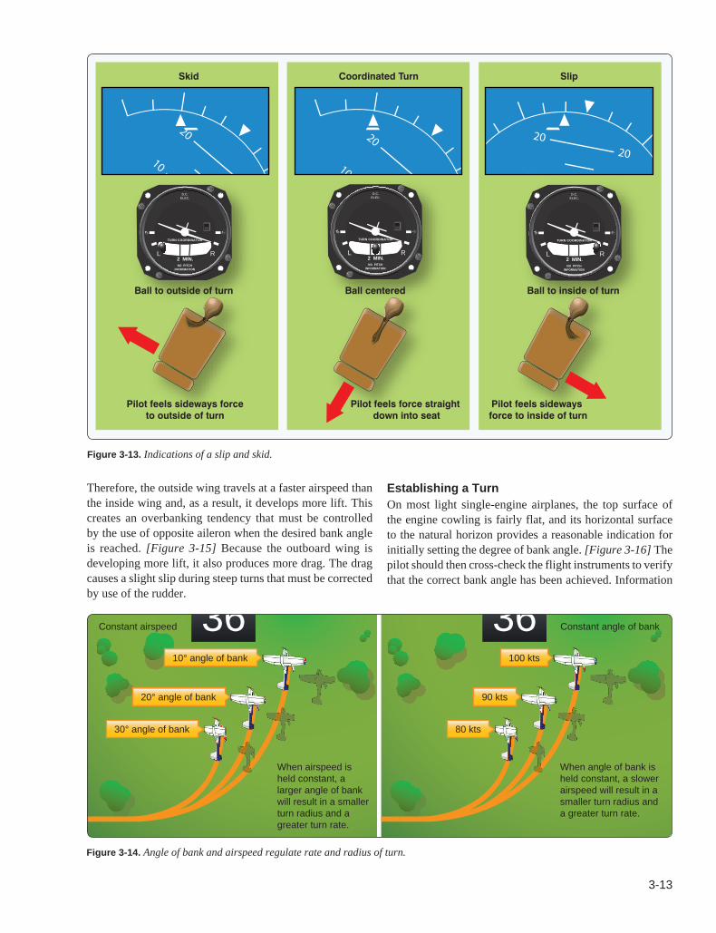
Figure 3-14. Angle of bank and airspeed regulate rate and radius of turn.
Figure 3-13. Indications of a slip and skid.
36Constant airspeed
10° angle of bank
20° angle of bank
30° angle of bank
36 Constant angle of bank
100 kts
90 kts
80 kts
When airspeed is held constant, a larger angle of bank will result in a smaller turn radius and a greater turn rate.
When angle of bank is held constant, a slower airspeed will result in a smaller turn radius and a greater turn rate.
TURN COORDINATOR
2 MIN.
D.C.ELEC.
L RNO PITCH
INFORMATION
TURN COORDINATOR
2 MIN.
D.C.ELEC.
L RNO PITCH
INFORMATION
TURN COORDINATOR
2 MIN.
D.C.ELEC.
L RNO PITCH
INFORMATION
Skid Coordinated Turn Slip
Ball to outside of turn
Pilot feels sideways forceto outside of turn
Pilot feels force straight down into seat
Pilot feels sideways force to inside of turn
Ball to inside of turnBall centered
Therefore, the outside wing travels at a faster airspeed than the inside wing and, as a result, it develops more lift. This creates an overbanking tendency that must be controlled by the use of opposite aileron when the desired bank angle is reached. [Figure 3-15] Because the outboard wing is developing more lift, it also produces more drag. The drag causes a slight slip during steep turns that must be corrected by use of the rudder.
Establishing a TurnOn most light single-engine airplanes, the top surface of the engine cowling is fairly flat, and its horizontal surface to the natural horizon provides a reasonable indication for initially setting the degree of bank angle. [Figure 3-16] The pilot should then cross-check the flight instruments to verify that the correct bank angle has been achieved. Information

3-14
Figure 3-16. Visual reference for angle of bank.
OBS
N
E
S
W
333
24
2115
12
30
6
NAV
GS
OBS
N
E
S
W
333
24
2115
12
30
6
33
30
6
3
W
E
N
Reference angle
XPDR 5537 IDNT LC
L23:00:34
VOR 1
270°
2
1
1
2
3300
3200
3100
4000
2900
2800
2300
60
203000
3000
130
120
110
90
80
70
1100
9
TAS 100KT
NAV1 108.00 113.00
NAV2 108.00 110.60
134.000118.000 COM1
123.800 118.000 C
OM2
WPT _ _ _ _ _ _ DIS _ _ ._ NM DTK _ _ _°
TRK 360°
MAP - NAVIGATION MAP
ADF/DME
MSG
D195I D212I
A212IHDG UP
10 NM
NAV1 117.60 117.9
0
NAV2 117.90 117.6
0
27.3
2090
Reference angle
Figure 3-15. Overbanking tendency.
Outer wing travels greater distance • Higher speed • More lift
Inner wing travels shorter distance • Lower speed • Less lift
Overbanking Tendency
obtained from the attitude indicator shows the angle of the wing in relation to the horizon.
The pilot’s seating position in the airplane is important as it affects the interpretation of outside visual references. A common problem is that a pilot may lean away from the turn in an attempt to remain in an upright position in relation to the horizon. This should be corrected immediately if the pilot is to properly learn to use visual references. [Figure 3-17]
Because most airplanes have side-by-side seating, a pilot does not sit on the airplane’s longitudinal axis, which is where the airplane rotates in roll. The pilot sits slightly off to one side, typically the left, of the longitudinal axis. Due to parallax error, this makes the nose of the airplane appear to rise when making a left turn (due to pilot lowering in relation to the longitudinal axis) and the nose of the airplane appear to descend when making right turns (due to pilot elevating in relation to the longitudinal axis). [Figure 3-18]
Beginning pilots should not use large aileron and rudder control inputs. This is because large control inputs produce rapid roll rates and allows little time for the pilot to evaluate and make corrections. Smaller flight control inputs result in slower roll rates and provide for more time to accurately complete the necessary pitch and bank corrections.
Some additional considerations for initiating turns are the following:
• If the airplane’s nose starts to move before the bank starts, the rudder is being applied too soon.
• If the bank starts before the nose starts turning or the nose moves in the opposite direction, the rudder is being applied too late.
• If the nose moves up or down when entering a bank, excessive or insufficient elevator back pressure is being applied.
After the bank has been established, all flight control pressures applied to the ailerons and rudder may be relaxed or adjusted, depending on the established bank angle, to compensate for the airplane’s inherent stability or overbanking tendencies. The airplane should remain at the desired bank angle with the proper application of aileron pressures. If the desired bank angle is shallow, the pilot needs to maintain a small amount of aileron pressure into the direction of bank including rudder to compensate for yaw effects. For medium bank angles, the ailerons and rudder should be neutralized. Steep bank angles require opposite aileron and rudder to prevent the bank from steepening.
Back pressure on the elevator should not be relaxed as the vertical component of lift must be maintained if altitude is to be maintained. Throughout the turn, the pilot should reference the natural horizon, scan for aircraft traffic, and occasionally cross-check the flight instruments to verify performance. A reduction in airspeed is the result of increased drag but is generally not significant for shallow bank angles. In steeper turns, additional

3-15
Figure 3-17. Correct and incorrect posture while seated in the airplane.
Figure 3-18. Parallax view.
Correct posture Incorrect posture
OBS
N
E
S
W
333
24
2115
1230
6
NAV
GS
OBS
N
E
S
W
333
24
2115
12
30
6
33
30
6
3
W
E
N
Left turn
OBS
N
E
S
W
333
24
21 15
12
30 6
NAV
GS
OBS
N
E
S
W
333
24
21 15
12
30 6
XPDR 1200 ALT LCL23:00:34
VOR 1
270°
2
1
1
2
-450
3300
3200
3100
4000
2900
2800
2300
60402030
1500130
120
110
90
80
70
4103
TAS 100KT
NAV1 108.00 113.00NAV2 108.00 110.60
134.000 118.000 COM1123.800 118.000 COM2
WPT _ _ _ _ _ _ DIS _ _ ._ NM DTK _ _ _° TRK 360°
MAP - NAVIGATION MAP
ADF/DME ADVISORY
D195I D212I
A212IHDG UP
10 NM
HDG 270° CRS 270°
H3X8
12.3NMPD2
NAV2
Natural horizon reference
Right turn
Pilot moves higher relative to roll axis
XPDR 1200 ALT LCL23:00:34
VOR 1
270°
2
1
1
2
200
3300
3200
3100
4000
2900
2800
2300
60402030
1500130
120
110
90
80
70
4103
TAS 100KT
NAV1 108.00 113.00NAV2 108.00 110.60
134.000 118.000 COM1123.800 118.000 COM2
WPT _ _ _ _ _ _ DIS _ _ ._ NM DTK _ _ _° TRK 360°
MAP - NAVIGATION MAP
ADF/DME ADVISORY
D195I D212I
A212IHDG UP
10 NM
HDG 270° CRS 270°
T4X3
12.4NMPD2NAV2 Roll axis
Rol
l axis
Natural horizon reference
Pilot moves lower relative to roll axis
power may be required to maintain airspeed. If altitude is not being maintained during the turn, the pitch attitude should be corrected in relation to the natural horizon and cross-checked with the flight instruments to verify performance.
Steep turns require accurate, smooth, and timely flight control inputs. Minor corrections for pitch attitude are accomplished with proportional elevator back pressure while the bank angle is held constant with the ailerons. However, during steep turns, it is not uncommon for a pilot to allow the nose to get excessively low resulting in a significant loss in altitude in a very short period of time. The recovery sequence requires that the pilot first reduce the angle of bank with coordinated use of opposite aileron and rudder and then increase the pitch attitude by increasing elevator back pressure. If recovery from an excessively nose-low, steep bank condition is attempted by use of the elevator only, it only causes a steepening of the bank and unnecessary stress on the airplane. Steep turn
performance can be improved by an appropriate application of power to overcome the increase in drag and trimming additional elevator back pressure as the bank angle goes beyond 30°. This tends to reduce the demands for large control inputs from the pilot during the turn.
Since the airplane continues turning as long as there is any bank, the rollout from the turn must be started before reaching the desired heading. The amount of lead required to rollout on the desired heading depends on the degree of bank used in the turn. A rule of thumb is to lead by one-half the angle of bank. For example, if the bank is 30°, lead the rollout by 15°. The rollout from a turn is similar to the roll-in except the flight controls are applied in the opposite direction. Aileron and rudder are applied in the direction of the rollout or toward the high wing. As the angle of bank decreases, the elevator pressure should be relaxed as necessary to maintain altitude. As the wings become level, the flight control pressures should
3-16
be smoothly relaxed so that the controls are neutralized as the airplane returns to straight-and-level flight. If trim was used, such as during a steep turn, forward elevator pressure may be required until the trim can be adjusted. As the rollout is being completed, attention should be given to outside visual references, as well as the flight instruments to determine that the wings are being leveled and the turn stopped.
For outside references, select the horizon and another point ahead. If those two points stay in alignment, the airplane is tracking to that point as long as there is not a crosswind requiring a crab angle. It would also be a good idea to include VFR references for heading as well and pitch. A pilot holds course in VFR by tracking to a point in front of the compass, with only glances at the compass to ensure he or she is still on course. This reliance on a surface point does not work when flying over water or flat snow covered surfaces. In these conditions, the pilot must rely on the compass or gyro-heading indicator.
Because the elevator and ailerons are on one control, practice is required to ensure that only the intended pressure is applied to the intended flight control. For example, a beginner pilot is likely to unintentionally add pressure to the pitch control when the only bank was intended. This cross-coupling may be diminished or enhanced by the design of the flight controls; however, practice is the appropriate measure for smooth, precise, and accurate flight control inputs. For example, diving when turning right and climbing when turning left in airplanes is common with stick controls, because the arm tends to rotate from the elbow joint, which induces a secondary arc control motion if the pilot is not extremely careful. Likewise, lowering the nose is likely to induce a right turn, and raising the nose to climb tends to induce a left turn. These actions would apply for a pilot using the right hand to move the stick. Airplanes with a control wheel may be less prone to these inadvertent actions, depending on control positions and pilot seating. In any case, the pilot must retain the proper sight picture of the nose following the horizon, whether up, down, left or right and isolate undesired motion. It is essential that flight control coordination be developed because it is the very basis of all fundamental flight maneuvers.
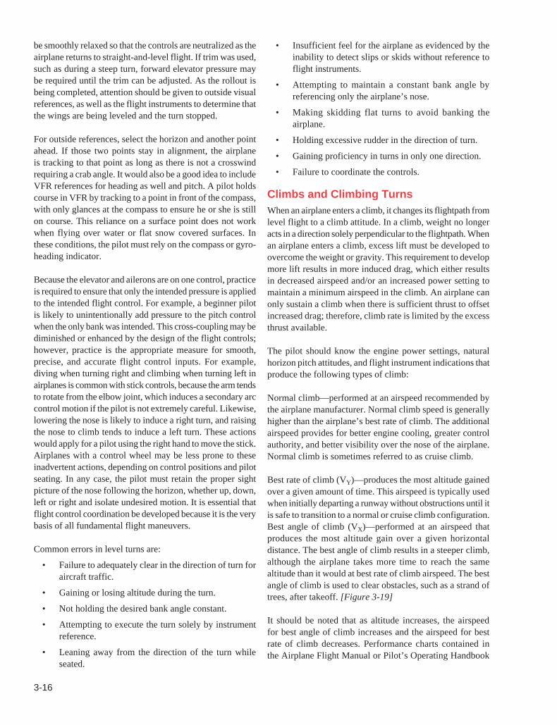
Common errors in level turns are:
• Failure to adequately clear in the direction of turn for aircraft traffic.
• Gaining or losing altitude during the turn.
• Not holding the desired bank angle constant.
• Attempting to execute the turn solely by instrument reference.
• Leaning away from the direction of the turn while seated.
• Insufficient feel for the airplane as evidenced by the inability to detect slips or skids without reference to flight instruments.
• Attempting to maintain a constant bank angle by referencing only the airplane’s nose.
• Making skidding flat turns to avoid banking the airplane.
• Holding excessive rudder in the direction of turn.
• Gaining proficiency in turns in only one direction.
• Failure to coordinate the controls.
Climbs and Climbing TurnsWhen an airplane enters a climb, it changes its flightpath from level flight to a climb attitude. In a climb, weight no longer acts in a direction solely perpendicular to the flightpath. When an airplane enters a climb, excess lift must be developed to overcome the weight or gravity. This requirement to develop more lift results in more induced drag, which either results in decreased airspeed and/or an increased power setting to maintain a minimum airspeed in the climb. An airplane can only sustain a climb when there is sufficient thrust to offset increased drag; therefore, climb rate is limited by the excess thrust available.
The pilot should know the engine power settings, natural horizon pitch attitudes, and flight instrument indications that produce the following types of climb:
Normal climb—performed at an airspeed recommended by the airplane manufacturer. Normal climb speed is generally higher than the airplane’s best rate of climb. The additional airspeed provides for better engine cooling, greater control authority, and better visibility over the nose of the airplane. Normal climb is sometimes referred to as cruise climb.
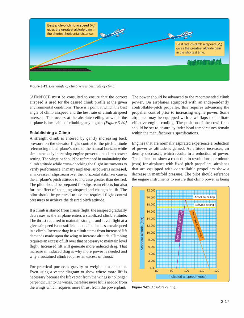
Best rate of climb (VY)—produces the most altitude gained over a given amount of time. This airspeed is typically used when initially departing a runway without obstructions until it is safe to transition to a normal or cruise climb configuration. Best angle of climb (VX)—performed at an airspeed that produces the most altitude gain over a given horizontal distance. The best angle of climb results in a steeper climb, although the airplane takes more time to reach the same altitude than it would at best rate of climb airspeed. The best angle of climb is used to clear obstacles, such as a strand of trees, after takeoff. [Figure 3-19]
It should be noted that as altitude increases, the airspeed for best angle of climb increases and the airspeed for best rate of climb decreases. Performance charts contained in the Airplane Flight Manual or Pilot’s Operating Handbook
3-17
Figure 3-19. Best angle of climb verses best rate of climb.
Figure 3-20. Absolute ceiling.
Best angle-of-climb airspeed (VX)gives the greatest altitude gain in the shortest horizontal distance.
Best rate-of-climb airspeed (VY)gives the greatest altitude gain in the shortest time.
Sta
ndar
d al
titud
e (fe
et)
Indicated airspeed (knots)
Bes
t ang
le o
f clim
b(V
X) B
est rate of climb(V
Y )
22,000
20,000
18,000
16,000
14,000
12,000
10,000
8,000
6,000
4,000
2,000
S.L.
Absolute ceiling
Service ceiling
80 90 100 110 120
(AFM/POH) must be consulted to ensure that the correct airspeed is used for the desired climb profile at the given environmental conditions. There is a point at which the best angle of climb airspeed and the best rate of climb airspeed intersect. This occurs at the absolute ceiling at which the airplane is incapable of climbing any higher. [Figure 3-20]
Establishing a ClimbA straight climb is entered by gently increasing back pressure on the elevator flight control to the pitch attitude referencing the airplane’s nose to the natural horizon while simultaneously increasing engine power to the climb power setting. The wingtips should be referenced in maintaining the climb attitude while cross-checking the flight instruments to verify performance. In many airplanes, as power is increased, an increase in slipstream over the horizontal stabilizer causes the airplane’s pitch attitude to increase greater than desired. The pilot should be prepared for slipstream effects but also for the effect of changing airspeed and changes in lift. The pilot should be prepared to use the required flight control pressures to achieve the desired pitch attitude.
If a climb is started from cruise flight, the airspeed gradually decreases as the airplane enters a stabilized climb attitude. The thrust required to maintain straight-and-level flight at a given airspeed is not sufficient to maintain the same airspeed in a climb. Increase drag in a climb stems from increased lift demands made upon the wing to increase altitude. Climbing requires an excess of lift over that necessary to maintain level flight. Increased lift will generate more induced drag. That increase in induced drag is why more power is needed and why a sustained climb requires an excess of thrust.
For practical purposes gravity or weight is a constant. Even using a vector diagram to show where more lift is necessary because the lift vector from the wings is no longer perpendicular to the wings, therefore more lift is needed from the wings which requires more thrust from the powerplant.
The power should be advanced to the recommended climb power. On airplanes equipped with an independently controllable-pitch propeller, this requires advancing the propeller control prior to increasing engine power. Some airplanes may be equipped with cowl flaps to facilitate effective engine cooling. The position of the cowl flaps should be set to ensure cylinder head temperatures remain within the manufacturer’s specifications.
Engines that are normally aspirated experience a reduction of power as altitude is gained. As altitude increases, air density decreases, which results in a reduction of power. The indications show a reduction in revolutions per minute (rpm) for airplanes with fixed pitch propellers; airplanes that are equipped with controllable propellers show a decrease in manifold pressure. The pilot should reference the engine instruments to ensure that climb power is being

3-18
Figure 3-21. Climb indications.
OBS
N
E
S
W
333
24
21 15
12
30
6
NAV
GS
OBS
N
E
S
W
333
24
21 15
12
30
6
XPDR 5537 IDNT LCL 10:12:34
VOR 1
270°
2
1
1
2
4300
4200
4100
4000
3900
3800
4300
3600
3500
3400
3300
3200
3100
60
204000
4000130
120
110
90
80
70
11009
TAS 106KTOAT 7°C
ALERTS
NAV1 108.00 113.00NAV2 108.00 110.60
134.000 118.000 COM1123.800 118.000 COM2
WPT _ _ _ _ _ _ DIS _ _ ._ NM DTK _ _ _° TRK 360°
HDG 270° CRS 270°
H3X8
12.3NMPD2
NAV2
+500
maintained and that pressures and temperatures are within the manufacturer’s limits. As power decreases in the climb, the pilot must continually advance the throttle or power lever to maintain specified climb settings.
The propeller effects during a climb and high power settings must be understood by the pilot. The propeller in most airplanes rotates clockwise when seen from the pilot’s position. As pitch attitude is increased, the center of thrust from the propeller moves to the right and becomes asymmetrical. This asymmetric condition is often called “P-factor.” This is the result of the increased AOA of the descending propeller blade, which is the right side of the propeller disc when seen from the cockpit. As the center of propeller thrust moves to the right, a left turning yawing moment moves the nose of the airplane to the left. This is compensated by the pilot through right rudder pressure. In addition, torque that acts opposite to the direction of propeller rotation causes the airplane to roll to the left. Under these conditions, torque and P-factor cause the airplane to roll and yaw to the left. To counteract this, right rudder and aileron flight control pressures must be used. During the initial practice of climbs, this may initially seem awkward; however, after some experience the correction for propeller effects becomes instinctive.
As the airspeed decreases during the climb’s establishment, the airplane’s pitch attitude tends to lower unless the pilot increases the elevator flight control pressure. Nose-up elevator trim should be used so that the pitch attitude can be maintained without the pilot holding back elevator pressure. Throughout the climb, since the power should be fixed at the climb power setting, airspeed is controlled by the use of elevator pressure. The pitch attitude to the natural horizon determines if the pitch attitude is correct and should be cross-checked to the flight instruments to verify climb performance. [Figure 3-21]
To return to straight-and-level flight from a climb, it is necessary to begin leveling-off prior to reaching the desired
altitude. Level-off should begin at approximately 10 percent of the rate of climb. For example, if the airplane is climbing at 500 feet per minute (fpm), leveling off should begin 50 feet prior to reaching the desired altitude. The pitch attitude must be decreased smoothly and slowly to allow for the airspeed to increase; otherwise, a loss of altitude results if the pitch attitude is changed too rapidly without allowing the airspeed to increase proportionately.
After the airplane is established in level flight at a constant altitude, climb power should be retained temporarily so that the airplane accelerates to the cruise airspeed. When the airspeed reaches the desired cruise airspeed, the throttle setting and the propeller control, if equipped, should be set to the cruise power setting and the airplane re-trimmed.
Climbing TurnsIn the performance of climbing turns, the following factors should be considered.
• With a constant power setting, the same pitch attitude and airspeed cannot be maintained in a bank as in a straight climb due to the increase in the total lift required.
• The degree of bank should not be too steep. A steep bank significantly decreases the rate of climb. The bank should always remain constant.
• It is necessary to maintain a constant airspeed and constant rate of turn in both right and left turns. The coordination of all flight controls is a primary factor.
• At a constant power setting, the airplane climbs at a slightly shallower climb angle because some of the lift is being used to turn the airplane.
All the factors that affect the airplane during level constant altitude turns affect the airplane during climbing turns. Compensation for the inherent stability of the airplane, overbanking tendencies,
3-19
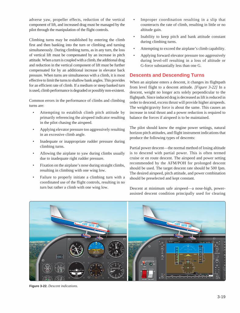
Figure 3-22. Descent indications.
OBS
N
E
S
W
333
24
21 15
12
30
6
NAV
GS
OBS
N
E
S
W
333
24
21 15
12
30
6
XPDR 5537 IDNT LCL 10:12:34
VOR 1
270°
2
1
1
2
-500
4300
4200
4100
4000
3900
3800
4300
3600
3500
3400
3300
3200
3100
60
204000
4000130
120
110
90
80
70
11009
TAS 106KTOAT 7°C
ALERTS
NAV1 108.00 113.00NAV2 108.00 110.60
134.000 118.000 COM1123.800 118.000 COM2
WPT _ _ _ _ _ _ DIS _ _ ._ NM DTK _ _ _° TRK 360°
HDG 270° CRS 270°
H3X8
12.3NMPD2
NAV2
adverse yaw, propeller effects, reduction of the vertical component of lift, and increased drag must be managed by the pilot through the manipulation of the flight controls.
Climbing turns may be established by entering the climb first and then banking into the turn or climbing and turning simultaneously. During climbing turns, as in any turn, the loss of vertical lift must be compensated by an increase in pitch attitude. When a turn is coupled with a climb, the additional drag and reduction in the vertical component of lift must be further compensated for by an additional increase in elevator back pressure. When turns are simultaneous with a climb, it is most effective to limit the turns to shallow bank angles. This provides for an efficient rate of climb. If a medium or steep banked turn is used, climb performance is degraded or possibly non-existent.
Common errors in the performance of climbs and climbing turns are:
• Attempting to establish climb pitch attitude by primarily referencing the airspeed indicator resulting in the pilot chasing the airspeed.
• Applying elevator pressure too aggressively resulting in an excessive climb angle.
• Inadequate or inappropriate rudder pressure during climbing turns.
• Allowing the airplane to yaw during climbs usually due to inadequate right rudder pressure.
• Fixation on the airplane’s nose during straight climbs, resulting in climbing with one wing low.
• Failure to properly initiate a climbing turn with a coordinated use of the flight controls, resulting in no turn but rather a climb with one wing low.
• Improper coordination resulting in a slip that counteracts the rate of climb, resulting in little or no altitude gain.
• Inability to keep pitch and bank attitude constant during climbing turns.
• Attempting to exceed the airplane’s climb capability.
• Applying forward elevator pressure too aggressively during level-off resulting in a loss of altitude or G-force substantially less than one G.
Descents and Descending TurnsWhen an airplane enters a descent, it changes its flightpath from level flight to a descent attitude. [Figure 3-22] In a descent, weight no longer acts solely perpendicular to the flightpath. Since induced drag is decreased as lift is reduced in order to descend, excess thrust will provide higher airspeeds. The weight/gravity force is about the same. This causes an increase in total thrust and a power reduction is required to balance the forces if airspeed is to be maintained.
The pilot should know the engine power settings, natural horizon pitch attitudes, and flight instrument indications that produce the following types of descents:
Partial power descent—the normal method of losing altitude is to descend with partial power. This is often termed cruise or en route descent. The airspeed and power setting recommended by the AFM/POH for prolonged descent should be used. The target descent rate should be 500 fpm. The desired airspeed, pitch attitude, and power combination should be preselected and kept constant.
Descent at minimum safe airspeed—a nose-high, power- assisted descent condition principally used for clearing
3-20
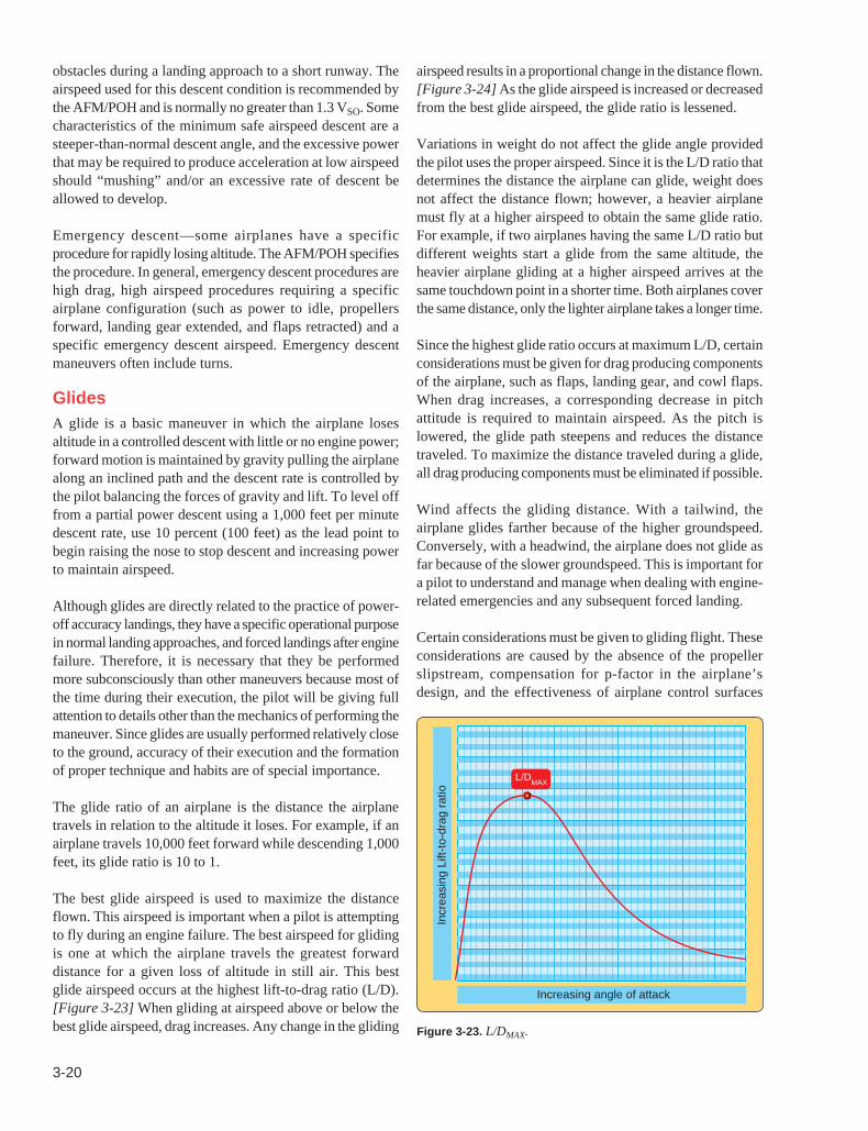
Figure 3-23. L/DMAX.
Incr
easi
ng L
ift-to
-dra
g ra
tio
Increasing angle of attack
L/DMAX
obstacles during a landing approach to a short runway. The airspeed used for this descent condition is recommended by the AFM/POH and is normally no greater than 1.3 VSO. Some characteristics of the minimum safe airspeed descent are a steeper-than-normal descent angle, and the excessive power that may be required to produce acceleration at low airspeed should “mushing” and/or an excessive rate of descent be allowed to develop.
Emergency descent—some airplanes have a specific procedure for rapidly losing altitude. The AFM/POH specifies the procedure. In general, emergency descent procedures are high drag, high airspeed procedures requiring a specific airplane configuration (such as power to idle, propellers forward, landing gear extended, and flaps retracted) and a specific emergency descent airspeed. Emergency descent maneuvers often include turns.
GlidesA glide is a basic maneuver in which the airplane loses altitude in a controlled descent with little or no engine power; forward motion is maintained by gravity pulling the airplane along an inclined path and the descent rate is controlled by the pilot balancing the forces of gravity and lift. To level off from a partial power descent using a 1,000 feet per minute descent rate, use 10 percent (100 feet) as the lead point to begin raising the nose to stop descent and increasing power to maintain airspeed.
Although glides are directly related to the practice of power-off accuracy landings, they have a specific operational purpose in normal landing approaches, and forced landings after engine failure. Therefore, it is necessary that they be performed more subconsciously than other maneuvers because most of the time during their execution, the pilot will be giving full attention to details other than the mechanics of performing the maneuver. Since glides are usually performed relatively close to the ground, accuracy of their execution and the formation of proper technique and habits are of special importance.
The glide ratio of an airplane is the distance the airplane travels in relation to the altitude it loses. For example, if an airplane travels 10,000 feet forward while descending 1,000 feet, its glide ratio is 10 to 1.
The best glide airspeed is used to maximize the distance flown. This airspeed is important when a pilot is attempting to fly during an engine failure. The best airspeed for gliding is one at which the airplane travels the greatest forward distance for a given loss of altitude in still air. This best glide airspeed occurs at the highest lift-to-drag ratio (L/D). [Figure 3-23] When gliding at airspeed above or below the best glide airspeed, drag increases. Any change in the gliding
airspeed results in a proportional change in the distance flown. [Figure 3-24] As the glide airspeed is increased or decreased from the best glide airspeed, the glide ratio is lessened.
Variations in weight do not affect the glide angle provided the pilot uses the proper airspeed. Since it is the L/D ratio that determines the distance the airplane can glide, weight does not affect the distance flown; however, a heavier airplane must fly at a higher airspeed to obtain the same glide ratio. For example, if two airplanes having the same L/D ratio but different weights start a glide from the same altitude, the heavier airplane gliding at a higher airspeed arrives at the same touchdown point in a shorter time. Both airplanes cover the same distance, only the lighter airplane takes a longer time.
Since the highest glide ratio occurs at maximum L/D, certain considerations must be given for drag producing components of the airplane, such as flaps, landing gear, and cowl flaps. When drag increases, a corresponding decrease in pitch attitude is required to maintain airspeed. As the pitch is lowered, the glide path steepens and reduces the distance traveled. To maximize the distance traveled during a glide, all drag producing components must be eliminated if possible.
Wind affects the gliding distance. With a tailwind, the airplane glides farther because of the higher groundspeed. Conversely, with a headwind, the airplane does not glide as far because of the slower groundspeed. This is important for a pilot to understand and manage when dealing with engine-related emergencies and any subsequent forced landing.
Certain considerations must be given to gliding flight. These considerations are caused by the absence of the propeller slipstream, compensation for p-factor in the airplane’s design, and the effectiveness of airplane control surfaces

3-21
Figure 3-24. Best glide speed provides the greatest forward distance for a given loss of altitude.
14 Too slowToo fast
Best glide speed
at slow speeds. With the absent propeller effects and the subsequent compensation for these effects, which is designed into many airplanes, it is likely that, during glides, slight left rudder pressure is required to maintain coordinated flight. In addition, the deflection of the flight controls to effect change is greater due to the relatively slow airflow over the control surfaces.
Minimum sink speed is used to maximize the time that the airplane remains in flight. It results in the airplane losing altitude at the lowest rate. Minimum sink speed occurs at an airspeed less than the best glide speed. It is important that pilots realize that flight at the minimum sink airspeed results in less distance traveled. Minimum sink speed is useful in flight situations where time in flight is more important than distance flown. An example is ditching an airplane at sea. Minimum sink speed is not an often published airspeed but generally is a few knots less than best glide speed. In an emergency, such as an engine failure, attempting to apply elevator back pressure to stretch a glide back to the runway is likely to lead the airplane landing short and may even lead to loss of control if the airplane stalls. This leads to a cardinal rule of airplane flying that a student pilot must understand and appreciate: The pilot must never attempt to “stretch” a glide by applying back-elevator pressure and reducing the airspeed below the airplane’s recommended best glide speed. The purpose of pitch control during the glide is to maintain the maximum L/D, which may require fore or aft flight control pressure to maintain best glide airspeed.
To enter a glide, the pilot should close the throttle and, if equipped, advance the propeller lever forward. With back pressure on the elevator flight control, the pilot should maintain altitude until the airspeed decreases to the recommended best glide speed. In most airplanes, as power is reduced, propeller slipstream decreases over the horizontal stabilizer, which decreases the tail-down force, and the airplane’s nose tends to lower immediately. To keep pitch attitude constant after a power change, the pilot must counteract the pitch down with a simultaneous increase in elevator back pressure. If the pitch attitude is allowed to decrease during glide entry, excess airspeed is carried into the glide and retards the attainment of the correct glide angle
and airspeed. Speed should be allowed to dissipate before the pitch attitude is decreased. This point is particularly important for fast airplanes as they do not readily lose their airspeed—any slight deviation of the airplane’s nose downwards results in an immediate increase in airspeed. Once the airspeed has dissipated to best glide speed, the pitch attitude should be set to maintain that airspeed. This should be done with reference to the natural horizon and with a quick reference to the flight instruments. When the airspeed has stabilized, the airplane should be trimmed to eliminate any flight control pressures held by the pilot. Precision is required in maintaining the best glide airspeed if the benefits are to be realized.
A stabilized, power-off descent at the best glide speed is often referred to as normal glide. The beginning pilot should memorize the airplane’s attitude and speed with reference to the natural horizon and noting the sounds made by the air passing over the airplane’s structure, forces on the flight controls, and the feel of the airplane. Initially, the beginner pilot may be unable to recognize slight variations in airspeed and angle of bank by vision or by the pressure required on the flight controls. The instructor should point out that an increase in sound levels denotes increasing speed, while a decrease in sound levels indicates decreasing speed. When a sound level change is perceived, a beginning pilot should cross-check the visual and pressure references. The beginning pilot must use all three airspeed references (sound, visual, and pressure) consciously until experience is gained, and then must remain alert to any variation in attitude, feel, or sound.
After a solid comprehension of the normal glide is attained, the beginning pilot should be instructed in the differences between normal and abnormal glides. Abnormal glides are those glides conducted at speeds other than the best glide speed. Glide airspeeds that are too slow or too fast may result in the airplane not being able to make the intended landing spot, flat approaches, hard touchdowns, floating, overruns, and possibly stalls and an accident.
Gliding TurnsThe absence of the propeller slipstream, loss of effectiveness of the various flight control surfaces at lower airspeeds, and designed-in aerodynamic corrections complicates the task of flight control coordination in comparison to powered flight for the inexperienced pilot. These principles should be thoroughly explained by the flight instructor so that the beginner pilot may be aware of the necessary differences in coordination.
Three elements in gliding turns that tend to force the nose down and increase glide speed are:
• Decrease in lift due to the direction of the lifting force
• Excessive rudder inputs as a result of reduced flight control pressures
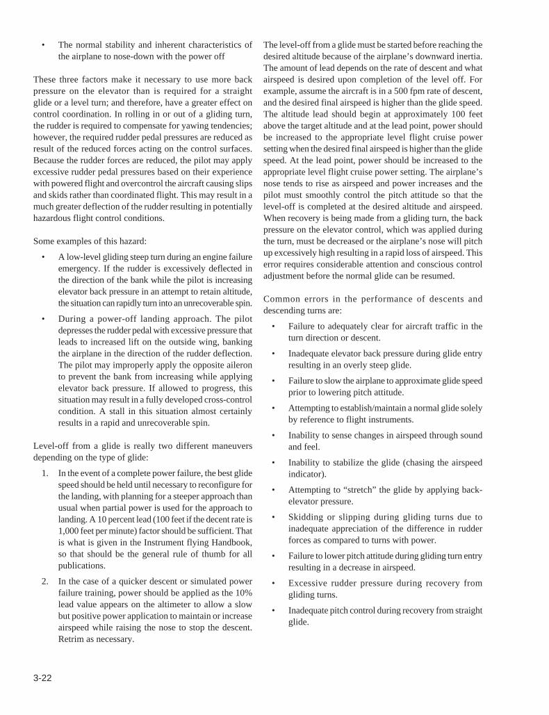
3-22
• The normal stability and inherent characteristics of the airplane to nose-down with the power off
These three factors make it necessary to use more back pressure on the elevator than is required for a straight glide or a level turn; and therefore, have a greater effect on control coordination. In rolling in or out of a gliding turn, the rudder is required to compensate for yawing tendencies; however, the required rudder pedal pressures are reduced as result of the reduced forces acting on the control surfaces. Because the rudder forces are reduced, the pilot may apply excessive rudder pedal pressures based on their experience with powered flight and overcontrol the aircraft causing slips and skids rather than coordinated flight. This may result in a much greater deflection of the rudder resulting in potentially hazardous flight control conditions.
Some examples of this hazard:
• A low-level gliding steep turn during an engine failure emergency. If the rudder is excessively deflected in the direction of the bank while the pilot is increasing elevator back pressure in an attempt to retain altitude, the situation can rapidly turn into an unrecoverable spin.
• During a power-off landing approach. The pilot depresses the rudder pedal with excessive pressure that leads to increased lift on the outside wing, banking the airplane in the direction of the rudder deflection. The pilot may improperly apply the opposite aileron to prevent the bank from increasing while applying elevator back pressure. If allowed to progress, this situation may result in a fully developed cross-control condition. A stall in this situation almost certainly results in a rapid and unrecoverable spin.
Level-off from a glide is really two different maneuvers depending on the type of glide:
1. In the event of a complete power failure, the best glide speed should be held until necessary to reconfigure for the landing, with planning for a steeper approach than usual when partial power is used for the approach to landing. A 10 percent lead (100 feet if the decent rate is 1,000 feet per minute) factor should be sufficient. That is what is given in the Instrument flying Handbook, so that should be the general rule of thumb for all publications.
2. In the case of a quicker descent or simulated power failure training, power should be applied as the 10% lead value appears on the altimeter to allow a slow but positive power application to maintain or increase airspeed while raising the nose to stop the descent. Retrim as necessary.
The level-off from a glide must be started before reaching the desired altitude because of the airplane’s downward inertia. The amount of lead depends on the rate of descent and what airspeed is desired upon completion of the level off. For example, assume the aircraft is in a 500 fpm rate of descent, and the desired final airspeed is higher than the glide speed. The altitude lead should begin at approximately 100 feet above the target altitude and at the lead point, power should be increased to the appropriate level flight cruise power setting when the desired final airspeed is higher than the glide speed. At the lead point, power should be increased to the appropriate level flight cruise power setting. The airplane’s nose tends to rise as airspeed and power increases and the pilot must smoothly control the pitch attitude so that the level-off is completed at the desired altitude and airspeed. When recovery is being made from a gliding turn, the back pressure on the elevator control, which was applied during the turn, must be decreased or the airplane’s nose will pitch up excessively high resulting in a rapid loss of airspeed. This error requires considerable attention and conscious control adjustment before the normal glide can be resumed.
Common errors in the performance of descents and descending turns are:
• Failure to adequately clear for aircraft traffic in the turn direction or descent.
• Inadequate elevator back pressure during glide entry resulting in an overly steep glide.
• Failure to slow the airplane to approximate glide speed prior to lowering pitch attitude.
• Attempting to establish/maintain a normal glide solely by reference to flight instruments.
• Inability to sense changes in airspeed through sound and feel.
• Inability to stabilize the glide (chasing the airspeed indicator).
• Attempting to “stretch” the glide by applying back-elevator pressure.
• Skidding or slipping during gliding turns due to inadequate appreciation of the difference in rudder forces as compared to turns with power.
• Failure to lower pitch attitude during gliding turn entry resulting in a decrease in airspeed.
• Excessive rudder pressure during recovery from gliding turns.
• Inadequate pitch control during recovery from straight glide.
3-23
• Cross-controlling during gliding turns near the ground.
• Failure to maintain constant bank angle during gliding turns.
Chapter SummaryThe four fundamental maneuvers of straight-and-level flight, turns, climbs, and descents are the foundation of basic airmanship. Effort and continued practice are required to master the fundamentals. It is important that a pilot consider the six motions of flight: bank, pitch, yaw and horizontal, vertical, and lateral displacement. In order for an airplane to fly from one location to another, it pitches, banks, and yaws while it moves over and above, in relationship to the ground, to reach its destination. The airplane must be treated as an aerodynamic vehicle that is subject to rigid aerodynamic laws. A pilot must understand and apply the principles of flight in order to control an airplane with the greatest margin of mastery and safety.