Embed Size (px)
DESCRIPTION
d
Citation preview

Page :3-1
SEP SEPARATOR SRPC M. Manual
Chapter 3- Theory of Operation
This information is CONFIDENTIAL and must not be copied in whole or any part, and should be filed accordingly by the addressee.It must not be shown to or discussed with anyone outside the SCHLUMBERGER organization.
TABLE OF CONTENTS
Chapter 3
Page
Theory of Operation 3
1. General Overview.....................................................................................................................3
1.1 Introduction...............................................................................................................................3
1.2 Features and Benefits. ...........................................................................................................3
1.3 Applications.............................................................................................................................3
1.4 Separator Selection Guidelines. ...........................................................................................3
1.5 Separator Identification..........................................................................................................4
2. Principles of Operation...........................................................................................................5
2.1 Introduction...............................................................................................................................5
2.2 Objectives. ...............................................................................................................................7
2.3 Principles of Operation...........................................................................................................7
2.4 Separation Processes. ..........................................................................................................7
2.5 Gravity and Density. ................................................................................................................8
2.6 Mechanical Separation Devices. ..........................................................................................8
2.7 Safety Devices ......................................................................................................................252.7.1.1.1 Vortex Meters and Flow Rates .................................................................................28
2.8 Piping Systems.....................................................................................................................36
2.9 Equipment..............................................................................................................................37
3. Operating Instruction............................................................................................................38
3.1 Rig-up.....................................................................................................................................38
3.1.1 Preliminary Adjustments and Checks.........................................................................39
3.1.2 Cleaning The Separator...............................................................................................41
3.1.3 Functional Check of Separator Isolation Valves........................................................42
3.1.4 Functional Checks on Separator Sight Glasses .......................................................42
3.1.5 Check of Separator Rupture Disk Rating and Mounting ..........................................43
3.1.6 Check of Pneumatic Controller Supply Circuit...........................................................44
3.1.7 Functional Check of Wizard-Gas ACV.......................................................................45
3.1.8 Functional Check of Liquid Level Control System.....................................................47

Page :3-2
SEP SEPARATOR SRPC M. Manual
Chapter 3- Theory of Operation
This information is CONFIDENTIAL and must not be copied in whole or any part, and should be filed accordingly by the addressee.It must not be shown to or discussed with anyone outside the SCHLUMBERGER organization.
3.1.9 General Instrumentation................................................................................................493.1.9.1 Calibration of a Bourdon Tube Pressure Gauge ..................................................................49
3.1.9.2 Calibration of Pressure and Temperature Recorders (Foxboro/Barton) ..................................50
3.1.10 Oil Metering Instrumentation........................................................................................513.1.10.1 Check of 2" Counter Gearing and Register System.........................................................51
3.1.10.2 Check of 3" Rotron Meters ...........................................................................................53
3.1.10.3 Onsite Meter Calibration with Water..............................................................................54
3.1.11 Gas Metering Instrumentation......................................................................................583.1.11.1 Check Securing of Straightening Vane ..........................................................................58
3.1.11.2 Daniel Orifice Meter (Functional Checks).......................................................................58
3.1.11.3 Daniel Orifice Meter Pressure Checks...........................................................................61
3.1.11.4 Model Identification of Barton Recorder..........................................................................64
3.1.11.5 Leak Checking of Barton Instrumentation Piping.............................................................65
3.1.11.6 Static Pressure Check on Barton Recorder....................................................................67
3.1.11.7 Differential Pressure Checks on Barton Recorder ...........................................................68
3.2 Run..........................................................................................................................................70
3.2.1 Separator Operations...................................................................................................703.2.1.1.1 Directing Flow through Separator (Initial)....................................................................70
3.2.1.1.2 Preparation.............................................................................................................70
3.2.1.1.3 PROCEDURE.........................................................................................................70
3.2.1.2 Flowrate Estimation during Filling up the Separator ............................................................72
3.2.1.3 Separator Operations during Choke Changes .....................................................................73
3.2.1.4 Separator System Response when Increasing Choke.........................................................73
3.2.1.5 Bypassing the Separator when Shutting in a Well ..............................................................74
3.2.1.5.1 Principle of Operation ..............................................................................................74
3.2.1.6 Inserting an Orifice-Plate under Line Pressure....................................................................76
3.2.1.7 Removing an orifice-plate under line pressure.....................................................................78
3.2.2 Combined Operations ..................................................................................................803.2.2.1 Clean Up ........................................................................................................................80
3.2.2.1.1 Limiting Factors of Clean Up ....................................................................................80
3.2.2.1.2 Main Phases of Clean Up.........................................................................................80
3.2.2.1.3 Flowing Back a liquid Cushion to the Tank.................................................................83
3.2.2.1.4 Check procedures for cleanup ..................................................................................84
3.2.2.2 Test Flow .......................................................................................................................90
3.2.2.2.1 Test Flow through Separator.....................................................................................90
3.2.2.2.2 Test Flow through Separator Procedure.....................................................................91
3.2.2.2.3 Procedure to Check for Critical Flow Condition...........................................................93

Page :3-3
SEP SEPARATOR SRPC M. Manual
Chapter 3- Theory of Operation
This information is CONFIDENTIAL and must not be copied in whole or any part, and should be filed accordingly by the addressee.It must not be shown to or discussed with anyone outside the SCHLUMBERGER organization.
3.2.2.2.4 Burner Operation Planning .......................................................................................94
3.2.2.2.5 How the system Works Together (initial setup) ..........................................................96
Chapter 3
Theory of Operation
1. General Overview
1.1 Introduction
The three-phase test separator is a versatile piece of equipment that allows separation, metering, and samplingof well effluent components. Designed for multiple tasks, the test separator does not separate fluids asperfectly as a production-station separator, but separation is effective enough for fluids to be reliably metered.
1.2 Features and Benefits.
The separator has the following features and benefits:
• Mechanical components inside the vessel improve the gravity separation process and reduce retentiontime.
• An orifice meter to measure the gas flow rate.• Two oil meters: a positive displacement meter for low flow rates and a vortex meter for high flow rates.• A positive displacement meter to measure the water flow rate.• A built-in shrinkage tester to calculate the shrinkage factor.• An adjustable oil-gas interface level to handle various flow rates and gas-oil ratios (GOR).• A pressure controller to adjust the separation pressure and improve separation efficiency.• The vessel is protected against overpressure by two different devices: a safety relief valve and a rupture
disc.• Several tapping points for taking oil, gas, and water samples.• Multiple dimensions and pressure ratings.
The test separator is capable of treating most types of fluid presently found in exploration wells including gas,gas condensate, light oil, heavy oil, foaming oil, oil containing water and impurities and H2S bearing fluids.
1.3 Applications.
In many ways, the separator is the central piece of equipment in the well testing setup. Most well tests requirea separator. It is used in all exploration tests and sometimes for production tests, when the permanentseparator is unavailable or not installed.
1.4 Separator Selection Guidelines.The principal criteria for selecting a separator are:• Project requirements related to working pressure, emulsion, foam, and cost considerations.• The recommended retention time for fluid inside the vessel is greater than one minute. If the flow rate is
high, a larger separator is needed to achieve the recommended retention time. Some jobs may requiremore than one separator to meet the recommended retention time.
• Weight restrictions can be dictated by crane lift capacity at the well site or access to the well site; forexample, only heli-portable separators can be used on some offshore rigs.

Page :3-4
SEP SEPARATOR SRPC M. Manual
Chapter 3- Theory of Operation
This information is CONFIDENTIAL and must not be copied in whole or any part, and should be filed accordingly by the addressee.It must not be shown to or discussed with anyone outside the SCHLUMBERGER organization.
Additional selection considerations are:• A differential pressure cell is needed for gas rate calculation.• A shrinkage tester is needed if one is not already fitted on the separator.• Check connection (cross-over) requirements. Connections need to be compatible with manifolds and
piping on rig lines.• A compressed air supply is needed for the level controllers.
1.5 Separator Identification
The separator can be identified by its working pressure (WP) rating, temperature rating, and its size. Thisinformation is stamped on a metal plate. It is also common to use colored bands (painted or taped) on theseparator for quick visual identification.
For current information, refer to the Schlumberger Equipment Guidelines.
Page :3-5
SEP SEPARATOR SRPC M. Manual
Chapter 3- Theory of Operation
This information is CONFIDENTIAL and must not be copied in whole or any part, and should be filed accordingly by the addressee.It must not be shown to or discussed with anyone outside the SCHLUMBERGER organization.
2. Principles of Operation
2.1 Introduction.
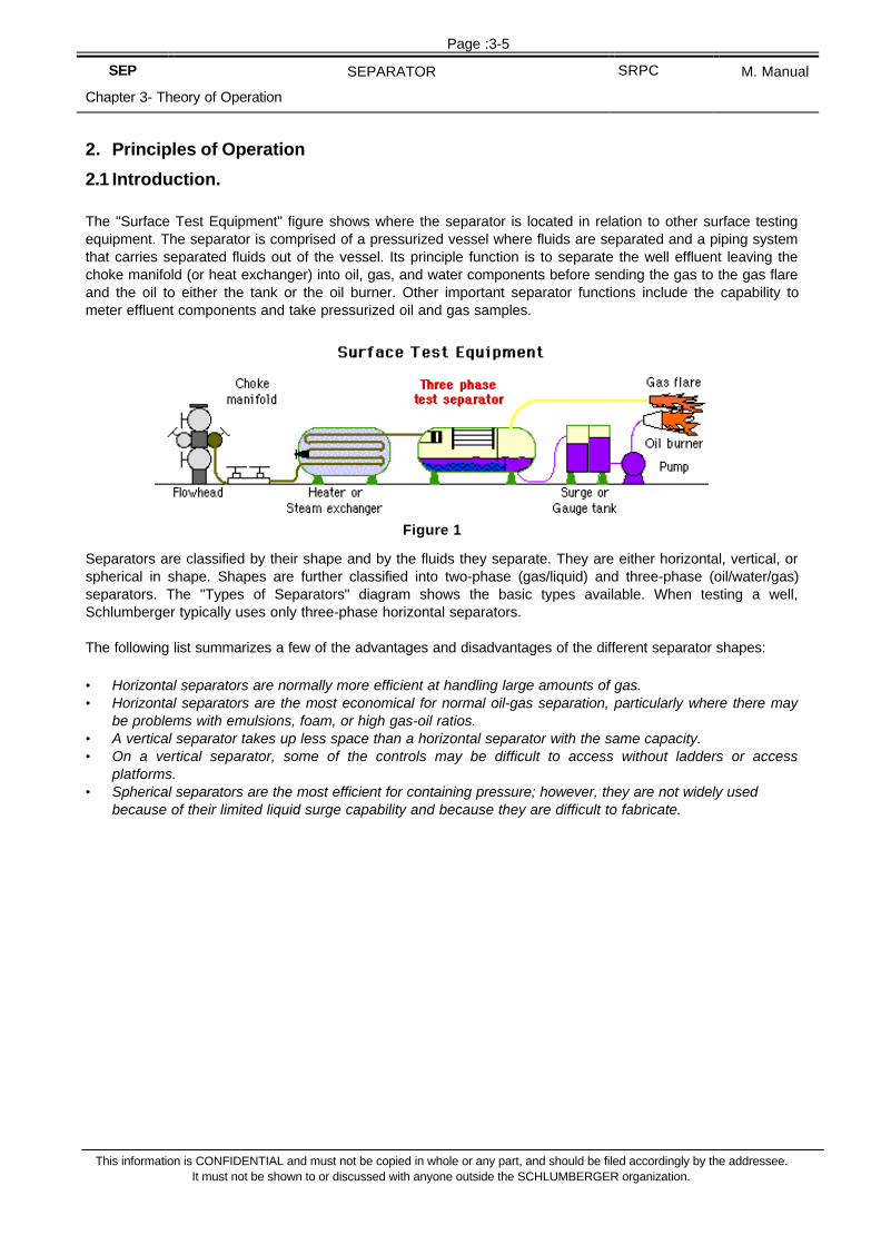
The "Surface Test Equipment" figure shows where the separator is located in relation to other surface testingequipment. The separator is comprised of a pressurized vessel where fluids are separated and a piping systemthat carries separated fluids out of the vessel. Its principle function is to separate the well effluent leaving thechoke manifold (or heat exchanger) into oil, gas, and water components before sending the gas to the gas flareand the oil to either the tank or the oil burner. Other important separator functions include the capability tometer effluent components and take pressurized oil and gas samples.
Separators are classified by their shape and by the fluids they separate. They are either horizontal, vertical, orspherical in shape. Shapes are further classified into two-phase (gas/liquid) and three-phase (oil/water/gas)separators. The "Types of Separators" diagram shows the basic types available. When testing a well,Schlumberger typically uses only three-phase horizontal separators.
The following list summarizes a few of the advantages and disadvantages of the different separator shapes:
• Horizontal separators are normally more efficient at handling large amounts of gas.• Horizontal separators are the most economical for normal oil-gas separation, particularly where there may
be problems with emulsions, foam, or high gas-oil ratios.• A vertical separator takes up less space than a horizontal separator with the same capacity.• On a vertical separator, some of the controls may be difficult to access without ladders or access
platforms.• Spherical separators are the most efficient for containing pressure; however, they are not widely used
because of their limited liquid surge capability and because they are difficult to fabricate.
Figure 1

Page :3-6
SEP SEPARATOR SRPC M. Manual
Chapter 3- Theory of Operation
This information is CONFIDENTIAL and must not be copied in whole or any part, and should be filed accordingly by the addressee.It must not be shown to or discussed with anyone outside the SCHLUMBERGER organization.
Figure 2

Page :3-7
SEP SEPARATOR SRPC M. Manual
Chapter 3- Theory of Operation
This information is CONFIDENTIAL and must not be copied in whole or any part, and should be filed accordingly by the addressee.It must not be shown to or discussed with anyone outside the SCHLUMBERGER organization.
2.2 Objectives.
Upon completion of this package, you should be able to:• Explain the purpose of the separator.• List the components of the separator and describe their functions.• Explain how to adjust the retention time for the separator.• Explain why the separator should be run at a constant pressure and how to control this pressure.• Describe the various types of separators and list their specifications.
Upon completion of the practical exercises for the Separator, you should be able to:• Perform a FIT and TRIM on a separator.• Read the gas flow recorder.• Read the oil flow recorders.• Direct the flow into the separator.• Bypass the flow from the separator.• Adjust the pressure in the separator.• Adjust the oil level in the separator.• Perform shrinkage measurements using the shrinkage tester.
2.3 Principles of Operation.
The operating principles for the separator are covered in the following topics:• Separation Processes• Pressure and Level Controllers• Safety Devices• Metering Devices• Piping Systems
2.4 Separation Processes.
Separators rely on these processes to separate liquid (oil and water) from gas:• Gravity and the difference in densities between oil, gas, and water.• Mechanical devices in the separator that are used to improve the separation process.• Altering the pressure and gas-liquid interface to further optimize separation.

Page :3-8
SEP SEPARATOR SRPC M. Manual
Chapter 3- Theory of Operation
This information is CONFIDENTIAL and must not be copied in whole or any part, and should be filed accordingly by the addressee.It must not be shown to or discussed with anyone outside the SCHLUMBERGER organization.
2.5 Gravity and Density.
In the separator, oil, gas, and water will naturally separate due to the effects of gravity and the difference indensity between effluent components. The denser effluent particles fall to the bottom and the lighter particlesrise to the top. Gas rises and liquid falls in the separator. The separator improves this natural separationprocess by retaining the fluid long enough to slow down its motion, allowing separation to occur.
About 95% of the liquid-gas separation inside the separator happens instantly. The relative densities of gas andliquid (oil and water) are typically in the ratio of 1 to 20 so their separation is quick, usually taking only a fewseconds. However, some liquid will remain in the gas in the form of a fine mist. This liquid must be separatedfrom the gas with the aid of mechanical devices for separation to be complete. The relative density of oil towater is typically in the ratio of .75 to 1, so separation is a bit longer: one or two minutes.
2.6 Mechanical Separation Devices.
To obtain good separation, speed up the separation process, and minimize retention time, the separator isequipped with mechanical devices. The function of these mechanical devices is explained here so you canunderstand the role they play in the separation process.
Figure 3

Page :3-9
SEP SEPARATOR SRPC M. Manual
Chapter 3- Theory of Operation
This information is CONFIDENTIAL and must not be copied in whole or any part, and should be filed accordingly by the addressee.It must not be shown to or discussed with anyone outside the SCHLUMBERGER organization.
• Deflector Plate
This plate is located in front of the inlet. It causes a rapid change in the direction andvelocity of the fluids, forcing the liquids to fall to the bottom of the vessel. The deflectorplate is responsible for the initial gross separation of liquid and gas.
• Coalescing Plates
These plates are arranged longitudinally in an inverted V-shape in the upper part of theseparator. The liquid droplets in the gas hit the plates and stick to them. As more gaspasses through the plates, more droplets coalesce to form bigger drops that fall to thebottom of the vessel.
• Foam Breaker
This piece of equipment is made of wire mesh, like the mist extractor. It prevents oil particles in the foam(comprised of oil and gas) from passing through the separator and being carried away with the gas.
• Mist Extractor
This piece of equipment is composed of a mass of wirenetting. Before leaving the separator, the gas streampasses through the mist extractor, causing the tiny oildroplets remaining in the gas to fall down.
• Weir Plate.
This plate, located at the bottom of the vessel, divides the separator into two compartments:oil and water. Provided that the water level is controlled, it only permits oil to overflow into theoil compartment.
• Vortex Breakers.
These breakers are located on the oil and wateroutlets. Their function is to break the swirling (vortex)effect that can occur when oil and water exit theseparator from their respective outlets. The vortexbreakers prevent any gas from being sucked awaywith the liquids.
• Pressure and Gas-Liquid Interface
To optimize separation, there are three main parameters that can be controlled:• The pressure inside the separator• The level of the gas-liquid interface• The temperature inside the separator
The goal is to achieve the best separation possible for a given effluent. Because variations in these parameterscan affect separation conditions, it's important to keep these parameters as constant and stable as possible.Although the temperature inside the separator is almost equal to the well effluent temperature and cannot be

Page :3-10
SEP SEPARATOR SRPC M. Manual
Chapter 3- Theory of Operation
This information is CONFIDENTIAL and must not be copied in whole or any part, and should be filed accordingly by the addressee.It must not be shown to or discussed with anyone outside the SCHLUMBERGER organization.
controlled (unless a heat exchanger is connected upstream of the separator), the pressure and gas-liquidinterface can be controlled to optimize oil and gas recovery.
The "Separation Problems" table shows two examples of how the pressure, gas-liquid interface, andtemperature can be used to control separation problems.

Page :3-11
SEP SEPARATOR SRPC M. Manual
Chapter 3- Theory of Operation
This information is CONFIDENTIAL and must not be copied in whole or any part, and should be filed accordingly by the addressee.It must not be shown to or discussed with anyone outside the SCHLUMBERGER organization.
• Separation Problems
Problem Causes Action
Liquidcarryover
High flow rateHigh liquid levelLow operating pressureWave action in separatorFoaming
Decrease flow rateLower oil/gas interfaceRaise operating pressure or decrease flow rateReduce sensitivity of oil level controllerIncrease pressure
Pooroil-gas
separation
High viscosityHigh separator pressure
Heat well effluentIncrease retention timeReduce pressure
Table 1
• Pressure and Level Controllers
This topic covers the controller systems and their associated equipment. The gas pressurecontroller and the oil and water level controllers maintain constant separation conditionsinside the tank. To adjust the separator pressure and the water and oil flow rates, all thecontrollers use automatic control valves (ACVs). The compressed air used to operate thecontrollers is filtered through an air scrubber. The air pressure is reduced by using pressureregulators mounted upstream of the controllers. Visual level indicators, called sight glasses,are used to monitor the oil-gas and oil-water interfaces inside the separator.
• Gas Pressure Controller
The internal separator pressure is provided by the gas that flows into the separator. The fluid inflow variesdepending on the flowing conditions of the well. To maintain a constant pressure in the separator, the fluidoutflow must be adjusted so it's as close as possible to the fluid inflow.

Page :3-12
SEP SEPARATOR SRPC M. Manual
Chapter 3- Theory of Operation
This information is CONFIDENTIAL and must not be copied in whole or any part, and should be filed accordingly by the addressee.It must not be shown to or discussed with anyone outside the SCHLUMBERGER organization.
• Simple Gas Pressure Controller
The most common method of controlling pressure is with a pressure controller that uses a control valve toautomatically react to any variation in separator pressure. When the pressure drops, the controller closes thevalve and when the pressure rises, the controller opens the valve. Once the separator operating pressure ismanually set at the pressure controller, the pressure in the vessel is maintained close to the selected value.
For safety purposes, this control valve is normally open. If for any reason the air pressure supply to the valve iscut, the vessel will not be over pressurized.
The separator pressure is applied directly to the Bourdon tube inside the pressure controller as shown in the"Gas Pressure Controller" figure. A change in the separator pressure deforms the Bourdon tube. Thisdeformation moves the flapper covering the nozzle away from or closer to the nozzle, causing it to leak air. Theair leak is used by the pressure controller to open or close the control valve that regulates the pressure in theseparator.

Page :3-13
SEP SEPARATOR SRPC M. Manual
Chapter 3- Theory of Operation
This information is CONFIDENTIAL and must not be copied in whole or any part, and should be filed accordingly by the addressee.It must not be shown to or discussed with anyone outside the SCHLUMBERGER organization.
• Complex Gas Pressure Controller
The "Gas Pressure Controller" figure above shows a simple model of a gas pressure controller. In this simplesystem, the valve is either wide open or closed, causing the separator pressure to oscillate between aminimum and maximum pressure value.
The actual gas pressure controller mounted on the separator is more complex. In contrast to the simple model,the actual gas pressure controller allows the desired working pressure to be set and utilizes proportional bandcontrol to adjust the valve stroke, ensuring smooth regulation of the separator pressure.
For the complex system shown in the "Gas Pressure Controller - Proportional Action" diagram, the desiredpressure is set by adjusting the set point lever. Adjusting this lever moves the nozzle either closer or fartheraway from the flapper to establish the set point pressure. Pressure from the separator is applied directly to theBourdon tube. The "Gas Pressure Controller - Proportional Action" diagram shows the gas pressure controlsystem in a state of equilibrium with the separator pressure stable.

Page :3-14
SEP SEPARATOR SRPC M. Manual
Chapter 3- Theory of Operation
This information is CONFIDENTIAL and must not be copied in whole or any part, and should be filed accordingly by the addressee.It must not be shown to or discussed with anyone outside the SCHLUMBERGER organization.
The following lists describe what happens to the system shown in the "Gas Pressure Controller - ProportionalAction" diagram when the separator pressure rises and falls.
When the separator pressure decreases, the set pressure is maintained by• The Bourdon tube moves the flapper toward the nozzle, closing the gap between the nozzle and the
flapper.• Because chamber A is continuously supplied with air through orifice B, the reduction in the size of the air
passage between the nozzle and the flapper causes the air pressure in chamber A of the relay to build up.• The pressure build up in chamber A pushes diaphragms C and D upward, causing supply valve E to open.• Air supply pressure enters chamber F and flows to the automatic control valve (ACV), causing it to throttle
closer to its seat and reducing the flow of gas from separator thereby increasing its pressure.• Pressure in chamber F increases until diaphragms C and D are pushed back to their original positions,
causing valve E to close and returning the system to a state of equilibrium.• At the same time that air flows to the ACV, it also flows through the proportional band valve to the bellows
G. This air pressure causes the flapper to move away from the nozzle which stops the build up of pressurein chamber A and restores the system to a state of equilibrium.
As a result, the pressure on the ACV valve is increased (causing it to throttle closer to its seat) and theseparator pressure is restored to its set pressure.
When the separator pressure increases, the set pressure is maintained by• The Bourdon tube moves the flapper away from the nozzle, widening the gap between the nozzle and the
flapper.• This causes the air pressure in chamber A of the relay to decrease.• The pressure drop in chamber A and the action of the spring H causes diaphragms C and D to move down.• Air from the ACV starts to bleed off to the atmosphere through chamber I. This reduction in pressure
causes the ACV valve to open under the action of its spring.• At the same time that air flows from the ACV to the atmosphere, the air pressure in bellows G decreases,
causing the flapper to move closer to the nozzle. This action will cause the pressure in chamber A toincrease enough to close the passage between chambers F and I.
As a result, the pressure on the ACV is decreased (causing it to throttle away from its seat) and the separatorpressure is restored to its set pressure.
Proportional Band Valve
As shown in the "Gas Pressure Controller - Proportional Action" diagram, the pressure going from relaychamber F to the ACV also goes to the proportional band three-way valve. The orifice inlet for this valve isadjustable. This allows the amount of air pressure sent to bellows G (the proportional band bellows) to vary.This variation changes the clearance between the flapper and nozzle.
The proportional band is independent of the set point pressure, but dependent on the Bourdon tube pressurerating. The proportional band setting is expressed as a percentage, based on the Bourdon tube pressure rating,as described in the following examples. This percentage can vary between 0 and 100%. For example, when theproportional band for the Fisher 4150 pressure controller (shown in the "Gas Pressure Controller - ProportionalAction" diagram) is fully closed, it corresponds to a proportional band setting of approximately 3%.
The following examples show how a narrow (5%) and a wide setting (50%) of the proportional band changeshow the system reacts to a variation in pressure.• The pressure controller is equipped with a Bourdon tube with a pressure rating of 1000 psi.• The set point for the separator pressure is 400 psi.

Page :3-15
SEP SEPARATOR SRPC M. Manual
Chapter 3- Theory of Operation
This information is CONFIDENTIAL and must not be copied in whole or any part, and should be filed accordingly by the addressee.It must not be shown to or discussed with anyone outside the SCHLUMBERGER organization.
If the proportional band is set at 50% of the Bourdon tube rating of 1000 psi, this means that the ACV will befully closed when the separator pressure reaches 150 psi and fully open when the separator pressure reaches650 psi. At this wide setting, the system is not very sensitive to small pressure variations. It will take a largepressure variation of 250 psi on either side of the separator set point of 400 psi to either close or open the valve.
50% of 1000 psi=500 psi 500 psi / 2=250 psi 400 + 250=650 psi 400 - 250=150 psi
In contrast, if the proportional band is set at 5% of the Bourdon tube rating of 1000 psi, the ACV will be fullyclosed when the separator pressure reaches 375 psi and fully open when the separator pressure reaches 425psi. At this narrow setting, the system is sensitive to small pressure variations. The system will either close oropen the valve for a relatively small pressure variation of 25 psi on either side of the separator set point of 400psi.
5% of 1000 psi=50 psi50 psi / 2=25 psi400 + 25=425 psi400 - 25=375 psi
• Oil Level Controller
The level of the liquid-gas interface inside the separator should be kept constant to maintain steady separationconditions. A variation in this level changes the volume of gas and liquid in the separator, which in turn affectsthe speed and the retention time of the two fluids. The initial set point for the liquid-gas level depends on thegas-oil ratio (GOR) of the well effluent.
• If the GOR is high, more volume in the separator needs to be reserved for gas so a low oil level is required.• If the GOR is low, more volume in the separator needs to be reserved for the oil, so a high oil level is
required.
To cover different GORs, from the oil level controller, the oil level can be adjusted between two values: plus orminus 6 in. of the center line of the separator. As a guideline, the level is initially fixed at the center line andfurther level adjustments are made based on the GOR.

Page :3-16
SEP SEPARATOR SRPC M. Manual
Chapter 3- Theory of Operation
This information is CONFIDENTIAL and must not be copied in whole or any part, and should be filed accordingly by the addressee.It must not be shown to or discussed with anyone outside the SCHLUMBERGER organization.

Page :3-17
SEP SEPARATOR SRPC M. Manual
Chapter 3- Theory of Operation
This information is CONFIDENTIAL and must not be copied in whole or any part, and should be filed accordingly by the addressee.It must not be shown to or discussed with anyone outside the SCHLUMBERGER organization.
Simple Oil Level Controller
Oil level controllers commonly employ a plunger attached to a controller to open or close a control valve thatregulates the oil level. This controller actuates one of the two regulation valves on the oil outlet: a large and asmall diameter valve fitted in parallel. This system permits regulation of very low to very high oil flow rates,limited only by the maximum capacity of the separator.
When the oil level changes, according to the principle of Archimedes, the plunger is buoyed up by a force equalto the weight of the displaced fluid as shown in the "Oil Level Controller" and "Torque Tube" figures. Themovement of the plunger is converted, through a torque tube assembly, causing the flapper to move away fromor closer to the nozzle. In turn, the air leak from the nozzle opens or closes the control valve on the separatoroil outlet.
For safety purposes, the control valves on the oil outlet are normally closed. If for any reason the air pressuresupply to these valves is cut, this problem should be detected fast enough to prevent oil from backing up intothe separator. Oil buildup in the separator can cause oil to outflow into the gas line where it eventually reaches

Page :3-18
SEP SEPARATOR SRPC M. Manual
Chapter 3- Theory of Operation
This information is CONFIDENTIAL and must not be copied in whole or any part, and should be filed accordingly by the addressee.It must not be shown to or discussed with anyone outside the SCHLUMBERGER organization.
the flare and pollutes the environment. Conversely, if the control valves on the oil outlet were open, oil couldbuild up in the tank, causing similar problems.

Page :3-19
SEP SEPARATOR SRPC M. Manual
Chapter 3- Theory of Operation
This information is CONFIDENTIAL and must not be copied in whole or any part, and should be filed accordingly by the addressee.It must not be shown to or discussed with anyone outside the SCHLUMBERGER organization.
• Complex Oil Level Controller
The "Oil Level Controller" figure above shows a simple model of an oil level controller. In this simple system, thevalve is either wide open or closed, causing the separator oil level to constantly fluctuate between a minimumand a maximum level.
The actual oil level controller mounted on the separator is more complex. In contrast to the simple model, theactual oil level controller allows the desired oil level to be set and utilizes a proportional band control to adjustthe valve stroke, ensuring smooth regulation of the separator oil level.
For the complex system shown in the "Oil Level Controller - Proportional Action" diagram, the desired liquidlevel is set by adjusting the set point lever. Adjusting this lever moves the nozzle, mounted on the Bourdontube, closer or farther away from the flapper. This set point lever allows the desired level of liquid to be set(providing that the oil level is between the top and the bottom of the plunger). The diagram shows the oil levelcontroller in a state of equilibrium: the oil level is set in the middle of the plunger and the inlet flow is equal tothe outlet flow.
The following lists describe what happens to the system shown in the "Oil Level Controller - ProportionalAction" diagram when the inlet flow is greater than and less than the outlet flow.
When the inlet flow is greater than the outlet flow, the level of oil in the separator increases:
• The buoyant force of the liquid increases, lifting the plunger up. The flapper, connected to the plunger bythe torque tube, moves toward the nozzle.
• This displacement of the plunger moves the flapper up, closing the gap between the flapper and the nozzleand reducing the air passage. Because chamber A is constantly supplied with air through orifice B,the reduction in this air passage increases the pressure in chamber A.
• The pressure build up in chamber A pushes diaphragms C and D down, opening the supply valve E.• Air supply pressure enters chamber F and flows to the automatic control valve (ACV) causing it to throttle
away from its seat (opening the ACV). This action increases the oil outflow and causes the oil level to fall.

Page :3-20
SEP SEPARATOR SRPC M. Manual
Chapter 3- Theory of Operation
This information is CONFIDENTIAL and must not be copied in whole or any part, and should be filed accordingly by the addressee.It must not be shown to or discussed with anyone outside the SCHLUMBERGER organization.
• At the same time that the air flows to the ACV, it also flows through the proportional band valve to theBourdon tube. This air pressure causes the nozzle on the Bourdon tube to move away from the flapper.This action stops the pressure buildup in chamber A and restores the system to a state of equilibrium.

Page :3-21
SEP SEPARATOR SRPC M. Manual
Chapter 3- Theory of Operation
This information is CONFIDENTIAL and must not be copied in whole or any part, and should be filed accordingly by the addressee.It must not be shown to or discussed with anyone outside the SCHLUMBERGER organization.
As a result, the pressure on the ACV is increased (causing it to throttle away from its seat) and the separatoroil level is restored to its set level.
When the inlet flow is less than the outlet flow, the level of oil in the separator decreases:
• The flapper moves away from the nozzle, widening the gap between the nozzle and the flapper.• This causes the air pressure in chamber A of the relay to decrease.• The pressure drop in chamber A and the action of the spring G move diaphragms C and D up.• Air from the automatic control valve starts to bleed off to the atmosphere through chamber I. This
reduction in pressure causes the ACV to close under the action of its spring.• At the same time that air flows from the ACV to the atmosphere, the air pressure passing through
proportional band valve to the Bourdon tube decreases, causing the nozzle on the Bourdon tube to movecloser to the flapper. This action causes the pressure in chamber A to increase enough to close thepassage between chambers F and I.
As a result, the pressure on the ACV is decreased (causing it to throttle closer to its seat) and the oil level isrestored to its set level.
• Proportional Band Valve
As shown in the "Displacement-Type Controller" figure, the pressure from relaychamber F flows to the automatic control valve and also flows to theproportional band three-way valve. The orifice of this valve is adjustable so theamount of air pressure or "feedback" to the Bourdon tube can be set asdesired.
This figure represents a displacement type controller, one that does not float ontop of the liquid, but floats in the liquid and is displaced (moves up and down)as the liquid level changes. As shown in the diagram, to control the liquid levelthe liquid must be between points A and B. If the liquid level is below A orabove B, the controller will not be able to control the liquid level.
The proportional band setting is expressed as a percentage, based on the length of the plunger, as described inthe following examples. This percentage can vary from 0 to 100%. For example, if the proportional band is setat 100%, the liquid level would have to move from A to B or B to A to fully stroke the valve. In contrast, if theproportional band is set at 25%, the level of liquid would have to move 25% of the distance between A and B tofully stroke the valve.
Another way this relationship is expressed is based on the length of the level change that will cause the valveto fully stroke. For example, if the level change that causes a full stroke of the ACV is 8 in. and the float is 16in. long, the proportional band is set at 50% (50% proportional band).

Page :3-22
SEP SEPARATOR SRPC M. Manual
Chapter 3- Theory of Operation
This information is CONFIDENTIAL and must not be copied in whole or any part, and should be filed accordingly by the addressee.It must not be shown to or discussed with anyone outside the SCHLUMBERGER organization.
• Water Level Controller
The interface level between water and oil in the separator should be kept constant to prevent the water frompassing over the weir plate and flowing into the oil compartment. This is accomplished with a float connected toa water level controller that acts on a valve fitted to the water outlet.
The level of water is controlled with a float that floats in water but sinks in oil. The movement of the float istransmitted through a tube to a flapper that moves away from or closer to the nozzle, causing it to leak air. Theair leak from the nozzle is used to open or close a control valve on the separator water outlet.

Page :3-23
SEP SEPARATOR SRPC M. Manual
Chapter 3- Theory of Operation
This information is CONFIDENTIAL and must not be copied in whole or any part, and should be filed accordingly by the addressee.It must not be shown to or discussed with anyone outside the SCHLUMBERGER organization.
• Automatic Control Valves
The automatic control valves (ACV) for the oil, gas, and water controllers are designed to regulate the rate offlow in a pipe by varying its cross-sectional area in response to an air leak signal received from a controller.
The "Automatic Flow Control Valves" figure shows the two different types (normally open and normally closed)of control valves used in a separator.

Page :3-24
SEP SEPARATOR SRPC M. Manual
Chapter 3- Theory of Operation
This information is CONFIDENTIAL and must not be copied in whole or any part, and should be filed accordingly by the addressee.It must not be shown to or discussed with anyone outside the SCHLUMBERGER organization.
• Sight Glass
The sight glass is a visual level indicator. On the separator there's an oil sight glass to monitor the oil-gasinterface and a water sight glass to monitor the oil-water interface. The levels inside the separator can be seenthrough the glass.
This device is made of transparent glass housed in a steel chamber to withstand the pressure inside theseparator. In the event the glass breaks, the safety glass is equipped with safety valves that prevent fluidsinside the separator from escaping. The safety valve works using a ball that automatically seals off the tankfrom the sight glass using the pressure differential between the tank and the atmosphere. After a broken glassis changed, the ball needs to be pushed back in its groove so it can seal off the separator from the sight glass,in case another failure occurs. Use the stem tip to push the ball back by moving the handle about one quarterturn. Once the ball is in position, turn the handle back to return the stem to its original position.
• Air Scrubber
The air used to operate the oil, gas, and water controllers is provided by an air compressor. This air from thecompressor is first filtered using an air scrubber. The air scrubber is simply a vertical pot where the impuritiesand water settle. After the air is filtered, it is sent to pressure regulators where the air pressure is reduced to alevel that's acceptable for the instruments.

Page :3-25
SEP SEPARATOR SRPC M. Manual
Chapter 3- Theory of Operation
This information is CONFIDENTIAL and must not be copied in whole or any part, and should be filed accordingly by the addressee.It must not be shown to or discussed with anyone outside the SCHLUMBERGER organization.
2.7 Safety Devices
In case a malfunction causes the separatorpressure to rise to a dangerous level, thesedevices provide an emergency vent to theatmosphere. To prevent this type of failure,the separator is designed with two weakpoints--a safety relief valve and a rupturedisk--that are activated in case ofoverpressure. For the safety valve to operateproperly, it needs a needle valve and acheck valve.
• Safety Relief Valve
The safety relief valve is located on top of the separator. Its outlet is connected to the gas outlet line,downstream of the automatic control valve (ACV). When the safety relief valve is opened, gas is bled off to theflare. Depending on client requirements and local regulations, the outlet for the safety relief valve is sometimesconnected to a separate vent line.
The safety valve incorporates a bellows sealthat prevents separator fluid discharge fromentering the upper part of the valve that'sexposed to the atmospheric pressure. Thebellows has an effective area equal to thearea of the valve seat so the effect of anyback pressure from the valve outlet on setpressure is eliminated.
The set pressure is the pressure at whichyou want the safety relief valve to open. Theset pressure is adjusted by the force of aspring on a sealing disk that is exposed toseparator pressure.
The set pressure is normally set at 90% of the nominal (600 psi, 720 psi, or 1440 psi) separator workingpressure (WP). Due to temperature influence and calibration tolerances, it cannot be guaranteed that the safetyrelief valve will open at exactly 90% of WP. When setting the operating pressure, it's safe to assume that thevalve could open within a range of 85% to 95% of the WP. Consequently, the operating pressure in theseparator should be kept at or below 80% of WP to prevent accidental opening of the safety valve.
For example, for a 1440 psi WP separator, the set point is 90% of WP (1296 psi), and the operating range forthe valve is between 85% of WP (1224 psi) and 95% of WP (1368 psi). For this separator, the operatingpressure should be set at or below 80% of WP (1152 psi).

Page :3-26
SEP SEPARATOR SRPC M. Manual
Chapter 3- Theory of Operation
This information is CONFIDENTIAL and must not be copied in whole or any part, and should be filed accordingly by the addressee.It must not be shown to or discussed with anyone outside the SCHLUMBERGER organization.
• Check Valve
The check valve is located downstream of the safety reliefvalve. It is a free-swinging flapper valve that prevents backpressure in the gas outlet line from reaching the safetyrelief valve outlet, where it could possibly affect theopening of the safety relief valve.
• Needle Valve
The needle valve, connected between the safety reliefvalve and the check valve, ensures that any backpressure on the safety relief valve outlet is discharged tothe atmosphere. It should be small in size and must bechecked often to make sure it's clear. The needle valve iskept open during operations to detect leaks in the checkvalve and prevent leaks from exerting back pressure onthe safety relief valve. In the event the safety relief valveopens, the needle valve limits the size of the leak, makingit easy to control. If H2S is present, a line must beconnected to the needle valve to vent the gas away from personnel.
• Metering Devices
This topic looks at the meters used tomeasure flow rates for oil, gas, and wateras they leave the separator. To measurelow to high oil flow rates, a positivedisplacement meter and a vortex meterattached to the oil outlet line are used. Thegas flow rate is measured using an orificemeter, a type of differential pressure meter,attached to the gas outlet. Water flowrates are measured using a positivedisplacement meter, identical to thepositive displacement meter used tomeasure oil, that's attached to the wateroutlet. The shrinkage factor, measuredusing a shrinkage tester, represents acorrection factor used in oil volumecomputations. Gas scrubbers filter the gasthat's used to operate the differentialpressure recorder.

Page :3-27
SEP SEPARATOR SRPC M. Manual
Chapter 3- Theory of Operation
This information is CONFIDENTIAL and must not be copied in whole or any part, and should be filed accordingly by the addressee.It must not be shown to or discussed with anyone outside the SCHLUMBERGER organization.
• Oil Meters
The oil outlet is fitted with two parallel meters,making it possible to cover a broad range of flowrates. A single meter cannot accurately coverthe entire range (low to high) of flow rates. Oilmeters are used one at a time and the choicedepends on the flow rate. Low and medium flowrates are measured with a positivedisplacement meter, and high flow rates aremeasured with a vortex meter.
The positive displacement meter measures theliquid passing through it by separating the liquidinto segments and counting the segments.Liquid entering the meter strikes the bridge andis deflected downward, hitting the blades andturning the rotor in the right direction. The sealson the bridge prevent the liquid from returning tothe inlet side. The rotor movement is transferredto a register (readout device) with magneticcoupling.
Separators used for testing are usuallyequipped with a 2-in. diameter positivedisplacement meter that can measure a flowrate from 100 to 2200 barrels per day.
The ball vortex meter consists of a body with an offset chamber and a rotor that are mounted transversely to theflow stream. When liquid flows through themeter, a vortex is created in the offset chamber.The rotational velocity of the liquid vortex isproportional to the rate of flow. The rotormovement is transferred to a register (readoutdevice) with magnetic coupling.

Page :3-28
SEP SEPARATOR SRPC M. Manual
Chapter 3- Theory of Operation
This information is CONFIDENTIAL and must not be copied in whole or any part, and should be filed accordingly by the addressee.It must not be shown to or discussed with anyone outside the SCHLUMBERGER organization.
Separators used for testing can be equipped with a 2- or 3-in. diameter vortex meter. For this type of meter, theflow rate depends not only on the size but also on the type of bearings used as shown in the "Vortex Metersand Flow Rates" table.
2.7.1.1.1 Vortex Meters and Flow RatesMeter Type Rating with ball bearings
in barrels per/dayRating with sleeve bearings
in barrels/day2-in. vortex meter 850 to 6800 barrels/day 1700 to 8500 barrels/day3-in. vortex meter 2000 to 17,000 barrels/day 3400 to 22,000 barrels/day
Table 2
The oil meters located upstream from the automatic control valves operate under pressure, so the volume of oilmeasured is greater than if compared to standard conditions (atmospheric pressure and 60o F). Oil passing thecounter may be hot, which also increases the volume measured. After cooling, the real volume of oil will beless. This is because the oil leaving the separator still contains dissolved gas that will escape when thepressure drops. A first correction for this loss of volume must be applied and a second correction is applied fortemperature changes.
• Water Meter
The water outlet is fitted with a 2-in. diameter positive displacement meter that is identical to the positivedisplacement meter used to measure the oil flow rate.

Page :3-29
SEP SEPARATOR SRPC M. Manual
Chapter 3- Theory of Operation
This information is CONFIDENTIAL and must not be copied in whole or any part, and should be filed accordingly by the addressee.It must not be shown to or discussed with anyone outside the SCHLUMBERGER organization.
• Gas Meter
Before leaving the separator, the gas flow rate is measured using a type of differential pressure meter called anorifice meter. A calibrated orifice inserted in the gas stream creates a small pressure drop across the orificeplate. The pressure upstream and downstream of the orifice plate is used along with the gas temperature anddensity to calculate the gas flow rate.
At the beginning of a test, the gas flow rate is unknown. During the test, the gas flow rate may change;therefore, different sizes of orifice plates are used. The correct diameter of orifice plate is selected by trial anderror, so it's important to have an apparatus that allows the orifice plate to be changed without interrupting thegas flow. The orifice gas meter is designed for this purpose.

Page :3-30
SEP SEPARATOR SRPC M. Manual
Chapter 3- Theory of Operation
This information is CONFIDENTIAL and must not be copied in whole or any part, and should be filed accordingly by the addressee.It must not be shown to or discussed with anyone outside the SCHLUMBERGER organization.
Page :3-31
SEP SEPARATOR SRPC M. Manual
Chapter 3- Theory of Operation
This information is CONFIDENTIAL and must not be copied in whole or any part, and should be filed accordingly by the addressee.It must not be shown to or discussed with anyone outside the SCHLUMBERGER organization.
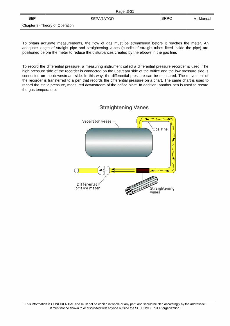
To obtain accurate measurements, the flow of gas must be streamlined before it reaches the meter. Anadequate length of straight pipe and straightening vanes (bundle of straight tubes fitted inside the pipe) arepositioned before the meter to reduce the disturbances created by the elbows in the gas line.
To record the differential pressure, a measuring instrument called a differential pressure recorder is used. Thehigh pressure side of the recorder is connected on the upstream side of the orifice and the low pressure side isconnected on the downstream side. In this way, the differential pressure can be measured. The movement ofthe recorder is transferred to a pen that records the differential pressure on a chart. The same chart is used torecord the static pressure, measured downstream of the orifice plate. In addition, another pen is used to recordthe gas temperature.

Page :3-32
SEP SEPARATOR SRPC M. Manual
Chapter 3- Theory of Operation
This information is CONFIDENTIAL and must not be copied in whole or any part, and should be filed accordingly by the addressee.It must not be shown to or discussed with anyone outside the SCHLUMBERGER organization.
The "Differential Pressure Recorder Process" diagram includes steps that show how the differential pressurerecorder works.

Page :3-33
SEP SEPARATOR SRPC M. Manual
Chapter 3- Theory of Operation
This information is CONFIDENTIAL and must not be copied in whole or any part, and should be filed accordingly by the addressee.It must not be shown to or discussed with anyone outside the SCHLUMBERGER organization.

Page :3-34
SEP SEPARATOR SRPC M. Manual
Chapter 3- Theory of Operation
This information is CONFIDENTIAL and must not be copied in whole or any part, and should be filed accordingly by the addressee.It must not be shown to or discussed with anyone outside the SCHLUMBERGER organization.

Page :3-35
SEP SEPARATOR SRPC M. Manual
Chapter 3- Theory of Operation
This information is CONFIDENTIAL and must not be copied in whole or any part, and should be filed accordingly by the addressee.It must not be shown to or discussed with anyone outside the SCHLUMBERGER organization.
• Gas Scrubbers
The gas used to operate the differential pressurerecorder is provided by the separator gas line. Thisgas is first filtered, on both the high and low pressurelines, using bottom gas scrubbers. These gasscrubbers are vertical pots where impurities, oil, andemulsion settle. Before the gas reaches the recorder,it is filtered again by the top gas scrubber. The topscrubbers act as a buffer between the gas and therecorder. In case the gas contains H2S or CO2(sourgas), the top scrubbers can be filled with hydraulic oilor diesel to prevent direct contact between the gasand the recorder.
• Shrinkage Tester
The shrinkage tester, usually attached to the oil sightglass of the separator, is used to estimate theshrinkage factor in the field. The shrinkage factor is acorrection factor used in the oil volume computations.It represents the amount of dissolved gas in the oilthat will be freed when the pressure drops from theseparator pressure to the atmospheric pressure.
The shrinkage tester consists of a bottle equipped witha graduated sight glass. Oil and gas will flow to thetester until the oil level reaches "0" on the vernier, corresponding to a set volume (Vo). The tester is thenisolated from the separator and the bottle pressure is bled off to the atmosphere slowly to prevent oil from beingreleased with the gas. This allows gas to be freed from the oil, so usually after 20 minutes, a new level can beread on the vernier. This new level corresponds to a new volume (V) of oil. The shrinkage factor read on thevernier is simply the V:Vo ratio, expressed as a percentage.

Page :3-36
SEP SEPARATOR SRPC M. Manual
Chapter 3- Theory of Operation
This information is CONFIDENTIAL and must not be copied in whole or any part, and should be filed accordingly by the addressee.It must not be shown to or discussed with anyone outside the SCHLUMBERGER organization.
2.8 Piping Systems
This topic describes the functions of the other equipment that's attached to the separator piping system: valves,a bypass manifold, and tapping points.
• ValvesThe "Separator Layout withBypass" drawing shows atypical separator piping layoutplus the manual ball valvesused to isolate the parts of thepiping not in use.
• Bypass Manifold
The bypass manifold betweenthe separator inlet and the oiland gas outlets permits effluentto be diverted to the burners orgas flare without passingthrough the separator. Thebypass manifold is used whenthe effluent doesn't need to beseparated; for example, at thebeginning of a test when thewell is first opened.
There's also a bypass line forthe separator oil meter that'sused when the oil flow ratedoes not need to be measured.
• Tapping Points
The oil and gas lines are equipped with tapping points and isolating valves, allowing fluid samples to be taken.Tapping points on oil, water, and gas lines can be used to connect pressure and temperature recorders. Theseparator is equipped with hammer wing unions for quick connection and disconnection of pipe work.
Page :3-37
SEP SEPARATOR SRPC M. Manual
Chapter 3- Theory of Operation
This information is CONFIDENTIAL and must not be copied in whole or any part, and should be filed accordingly by the addressee.It must not be shown to or discussed with anyone outside the SCHLUMBERGER organization.
2.9 Equipment.
Schlumberger has developed a wide range of separators that differ in size, modularity, portability, andtemperature rating which are available in working pressure ratings of 600, 720 and 1440 psi. All are H2Sresistant and each has special features:
The 600 psi is designed to be light, easily lifted, even by a small crane or an helicopter. Because of its lowerworking pressure, the metal is thinner so the overall vessel remains light.
The 720 psi is designed to handle high flow rates of oil, because its extended length provides a long retentiontime.
The 1440 psi version is by far the most commonly used separator. Due to its high working pressure, it canhandle higher flow rates of gas. The drawback is the higher overall weight for this separator.

Page :3-38
SEP SEPARATOR SRPC M. Manual
Chapter 3- Theory of Operation
This information is CONFIDENTIAL and must not be copied in whole or any part, and should be filed accordingly by the addressee.It must not be shown to or discussed with anyone outside the SCHLUMBERGER organization.
3. Operating Instruction
3.1 Rig-up

Page :3-39
SEP SEPARATOR SRPC M. Manual
Chapter 3- Theory of Operation
This information is CONFIDENTIAL and must not be copied in whole or any part, and should be filed accordingly by the addressee.It must not be shown to or discussed with anyone outside the SCHLUMBERGER organization.
3.1.1 Preliminary Adjustments and Checks
• Check easy operation of manual valves.
• Close gas supply pilot circuit valve PCV 1.
• Open upper gas bleed off valve GOV 6. :
This will serve to bleed off air contained in the separator vessel while filling it with water for further checksdescribed hereafter.
• Close gas sampling valve GOV 7.
• Close pressure gauge valve PGV 3.
• Switch the 3-way valve PCV 2 of the pilot circuit to external supply and connect it to the air supply (7 bar –100 psi max.).
• Open air supply.
• Bleed the scrubber via pilot circuit valve PCV 7. Close PVC 7.
• Adjust scrubber pressure to 40-50 psi (read P2).
• Open pilot circuit valves PCV 3 and 4.
• Bleed the drip wells of the 67 FR air pressure regulator (level troll, liquid level) to atmosphere.
• Adjust air regulator outlet pressures to :
- 15 to 20 psi for the 600/720 psi separators.
- 30 to 35 psi for the 1440 psi separator.
(read pressure gauge A of the level troll and liquid level controllers)
• Check the DANIEL operates freely and that orifice is moved "up".
• Close the DANIEL isolating valves GMV 5 and 6.
• If BARTON is already installed, disconnect the manifold or open the BARTON by-pass valve GMV 1, 2 andBARTON bleed-off valves GMV 3 to check for leaks at the DANIEL isolating valves should they occur.
• Close heater gas supply valve GOV 4.
• Check that automatic control valve GOV 1 is open.
• By moving the flapper of the Bourdon tube, check that the automatic control valve GOV 1 closes andcovers the whole of its stroke for a 3? 15 psi outlet signal (600/720 psi separator) or 6? 30 psi outlet (1440psi separator).
(read pressure gauge E).
Close gas outlet valve GOV 3 to isolate the Bourdon tube of the WIZARD.
• Open gas manual outlet valve GOV 2.
• Close separator by-pass valve V 3.
• Open separator inlet valve V 1.
• Close bleed-off valve V 2.
• Close separator by-pass valve V 4.
• Open bleeder valve GOV 5 :
It serves to check efficiency of the non return swing valve when submitted to separator pressure.

Page :3-40
SEP SEPARATOR SRPC M. Manual
Chapter 3- Theory of Operation
This information is CONFIDENTIAL and must not be copied in whole or any part, and should be filed accordingly by the addressee.It must not be shown to or discussed with anyone outside the SCHLUMBERGER organization.
• Close oil manual outlet valves OOV 3 and 4.
• Close bleeder valve OOV 5.
• Check that automatic control valves OOV 1 and 2 are closed.
• Open PCV 5. Check that automatic control valve OOV 1 remains closed.
• Move the flapper of the level troll towards the Bourdon tube and check that valve OOV 1 opens and coversthe whole of its stroke for a 3? 15 psi outlet signal (600/720 psi separators) or a 6? 30 psi outlet signal(1440 psi separator).
(read pressure gauge E).
Close PCV 5.
• Open PCV 6 and repeat the previous test with valve OOV 2.
Close PCV 6.
• Close water manual outlet valve WOV 2.
• Check that automatic control valve WOV 1 is closed.
• By moving the flapper of the liquid level controller towards the nozzle, check that valve WOV 1 opens andcovers the whole of its stroke a 3? 15 psi outlet signal (600/720 psi separator) or 6? 30 psi outlet (1440psi separator).
(read pressure gauge B).
• Close Rotron and Floco meter valves OMV 1 and 2.
• Open Rotron and Floco by-pass valve OMV 3.
• Open liquid level valve LLV 3 to shrinkage tester.
• Open half way liquid level valves LLV 1, 2, 6, 7 so that non return ball is impeded to seat under separatorinner pressure.
• Open either half way shrinkage tester valves SHV 3 and 4.
• Open SHV 1, 2 and 5.
• Remove upper plugs of all glass levels (water-oil, oil-gas, shrinkage tester).

Page :3-41
SEP SEPARATOR SRPC M. Manual
Chapter 3- Theory of Operation
This information is CONFIDENTIAL and must not be copied in whole or any part, and should be filed accordingly by the addressee.It must not be shown to or discussed with anyone outside the SCHLUMBERGER organization.
3.1.2 Cleaning The Separator
• Connect the pumping unit to the separator inlet and start pumping fresh water mixed if possible withdetergent or corrosion inhibitor into the separator.
• Check that water filling actuates (opens) the automatic control valve WOV 1.
This check is to ascertain that float has not been removed after a previous job !
• Open water manual outlet valve WOV 2 and circulate water for 15 minutes until clear liquid appears at thewater outlet. (take all necessary precautions to dispose off contaminated fluid coming from separator).
• Close WOV 2.
• Open bleed-off valve LLV 8. Check that clean water spills out from sight glass ass’y.
• Clean the sight glass if necessary with a tube brush introduced via the upper plug orifice while circulatingwater via LLV 8.
If sight glass is very dirty proceed as follows :
- Close LLV 8 and LLV 7.
- Fill the glass level with solvent or kerosene via upper plug port.
- Check that solvent overflows into the separator vessel via LLV 6.
- Clean the sight glass with a tube brush.
- Open LLV 8. Check that cleaning fluid flows correctly. Close LLV 8.
- Open LLV 7 half way. Check that water flows into the sight glass and pushes up cleaning fluid.
• Replace upper plug of the water-oil level ass’y.
• Continue filling the separator tank until water filling actuates the level troll (this proves that the float ismounted). Check that oil outlet valves OOV 1 or OOV 2 opens when opening respectively pilot controlvalves PCV 5 or PCV 6.
• Circulate water thru the oil outlet by opening for 10 minutes then closing manual outlet valve OOV 3.Check that water flow is clean.
• Repeat with OOV 4.
• Clean is necessary sight glass of the oil-gas level ass’y with a tube brush introduced via the upper plugorifice, while flowing water via LLV 5.
If sight glass is very dirty proceed as for the water-oil level ass’y.
• Replace upper plug of the oil-gas level ass’y.
• Open oil sampling valve LLV 4. Check that clean water flows thru this valve. Close LLV 4.
• Open bleed-off valve LLV 5. Check that clean water flows through this valve. Close LLV 5.
• Open bleeder valve SHV 7. Check that clean water flows through this valve. Close SHV 7.
• Clean sight glass of shrinkage tester following the same procedure as for the oil-gas level ass’y. replaceupper plug of the shrinkage tester sight glass.

Page :3-42
SEP SEPARATOR SRPC M. Manual
Chapter 3- Theory of Operation
This information is CONFIDENTIAL and must not be copied in whole or any part, and should be filed accordingly by the addressee.It must not be shown to or discussed with anyone outside the SCHLUMBERGER organization.
3.1.3 Functional Check of Separator Isolation Valves
Prior to pressure testing check the operation of all isolation valves
1.Turn valve from fully open to fully closed position (observe indicator pin).
• Check resistance to turn valve is feasible.• Check for increase in closing force when valve stem is almost turned 90° (seals are seating).
2.Reopen valve fully.
• Check that rotation of 90° can be performed and indicator pin is resting against indicator plate.
3.1.4 Functional Checks on Separator Sight Glasses
2 sight glasses are installed on the separator:
1.Liquid level sight glass (oil-gas)
2.Liquid interface sight glass (water-oil)
CHECK BEFORE PRESSURE TESTING
• Check visibility of both sight glasses and flush with solvent if necessary (helifuel).
• Fully open and close ball safety valves and check for smooth operation.
• Check sight glass for cracks and dents (possible damage during transportation).
• Check sight glass connecting piping with vessel (especially welding points) for cracks and bends.
CHECK DURING FILL OF SEPARATOR VESSEL
• Open all ball safety valves fully (turn counterclockwise then turn back into mid position).
• Observe level is raising in both sight glasses (no blockage in interconnecting piping or ball safety valves).

Page :3-43
SEP SEPARATOR SRPC M. Manual
Chapter 3- Theory of Operation
This information is CONFIDENTIAL and must not be copied in whole or any part, and should be filed accordingly by the addressee.It must not be shown to or discussed with anyone outside the SCHLUMBERGER organization.
DURING SEPARATOR VESSEL TEST
1.Observe for leaks with ball safety valves in fully open position.
2.Close ball safety valves and reopen to check for leaks in stem seals.
BALL SAFETY VALVE CHECK
1.At the end of the separator vessel test (vessel is still pressurized) have both ball safety valves fully open(stem turned fully counterclockwise).
2.Open LLV5 spontaneously and observe sight glass.
3.Balls of both ball safety valves should seat in safety position and isolate sight glass from separator vessel incase of sudden pressure drop.
4.Perform this test with both sight glasses.
3.1.5 Check of Separator Rupture Disk Rating and Mounting
RUPTURE DISK MOUNTING
Check that rupture disk is mounted correctly. The bursting pressure indicator must face up as indicated in .
This guarantees that hollow end of rupture disk faces up and rupture disk is mounted according tomanufacturer's specifications.

Page :3-44
SEP SEPARATOR SRPC M. Manual
Chapter 3- Theory of Operation
This information is CONFIDENTIAL and must not be copied in whole or any part, and should be filed accordingly by the addressee.It must not be shown to or discussed with anyone outside the SCHLUMBERGER organization.
RUPTURE DISK RATING
Check for rupture disk rating by reading information stamped onto bursting pressure indicator.
The rupture disk present has to comply with one of the following options.
In case of 1440 psi separator:
Option 1 Option 2 Option 3
Bursting disk M810710
(Preferable option)
Bursting disk M813601 Bursting disk M813600
Bursting pressure :
94°C = 201°F : 1584 psig
15°C = 59°F : 1690 psig
Bursting pressure :
94°C = 201°F : 1630 psig
Bursting pressure :
94°C = 201°F : 1483 psig
Check in history card for the elapsed time since last replacement.
3.1.6 Check of Pneumatic Controller Supply Circuit

Page :3-45
SEP SEPARATOR SRPC M. Manual
Chapter 3- Theory of Operation
This information is CONFIDENTIAL and must not be copied in whole or any part, and should be filed accordingly by the addressee.It must not be shown to or discussed with anyone outside the SCHLUMBERGER organization.
PROCEDURE
1.Open rig air supply and check supply pressure gauge GI.
2.Slowly open NI, purge moisture, and reclose.
3.Close pneumatic control circuits isolation valves N4, N5, N6, open N3.
4.Open N2 slowly then turn R1 clockwise and bleed moisture at N3.
5.Close N3 slowly observing G2.
6.Adjust regulator R1 to supply 50 psi pneumatic control circuit pressure (G2).
7.Adjust regulators R2, R3, R4 to 0 output pressure (turn counterclockwise).
8.Open isolation valves N4, N5, N6.
9.Open drain ports on regulators R2, R3, R4.
10.Purge all supply liners of moisture while regulating adjustment screw of regulators.
11.Turn adjustment screw of regulators counterclockwise until input pressure of all 3 controllers read 0.
12.Adjust regulators of all 3 controllers until input pressure is 5 psi above operating range of ACV.
NOTE – LOCK OPEN AND INDICATE RIG AIR SUPPLY POINTS TO PREVENT ACCIDENTAL CLOSINGDURING TEST. In order to prevent rig personnel from shutting off your instrument air supply accidentally, lock valvesopen by taping air supply points up, and clearly indicate that air supply is used for well test operations by installing asign in front of the supply point.
3.1.7 Functional Check of Wizard-Gas ACV
CALIBRATION CHECKS
1.Check pressure range.• Adjust proportional band to 100%.
• Adjust set point to give an output of 30 psi (or 15 psi) with signal pressure = 0.
• Apply Bourdon tube nominal pressure with DWT.
Observe: Output pressure drops to 6 psi (or 3 psi).

Page :3-46
SEP SEPARATOR SRPC M. Manual
Chapter 3- Theory of Operation
This information is CONFIDENTIAL and must not be copied in whole or any part, and should be filed accordingly by the addressee.It must not be shown to or discussed with anyone outside the SCHLUMBERGER organization.
2.Check set point adjustment.• Adjust proportional band to 10%, and set point to 50%.
• Apply 50% of Bourdon tube nominal pressure with DWT.
Observe : Output pressure stabilizes at 18 psi (or 9 psi).
• Release DWT signal pressure and move set point towards 0.
Observe:§ Output pressure shows 6 psi (or 3 psi) or less
§ ACV moves fully up. Mark position of indicator plate.
• Apply Bourdon tube nominal pressure with DWT and move set point towards 100%.
Observe:§ Output pressure shows 30 psi (or 15 psi) or more.
§ ACV moves fully down. Mark position of indicator plate.
3.Check proportional band.• Adjust proportional band to 25%.
• Adjust set point to give 30 psi (or 15 psi) output pressure.
• Apply 25% of Bourdon tube nominal pressure with DWT.
Observe : Output pressure drops to 6 psi (or 3 psi) or less.
• Increase to 75% of Bourdon tube nominal pressure with DWT.§ Adjust set point to give 30 psi (or 15 psi) output pressure.
• Increase to 100% of Bourdon tube nominal pressure with DWT.
Observe : Output pressure drops to 6 psi (or 3 psi) or less.
4.Check actuator operation.• Cycle ACV several times by moving set point.
• Check that valve travel is smooth and upper and lower limit remains according to marked positions (2).
Disconnect DWT and reconnect signal line from gas line.
NOTE – Depending on the type of ACV, there are two operating ranges of pneumatic circuits: 3-15 psi and 6-30psi.

Page :3-47
SEP SEPARATOR SRPC M. Manual
Chapter 3- Theory of Operation
This information is CONFIDENTIAL and must not be copied in whole or any part, and should be filed accordingly by the addressee.It must not be shown to or discussed with anyone outside the SCHLUMBERGER organization.
3.1.8 Functional Check of Liquid Level Control System
1.Check level range (perform during filling vessel).• Set proportional band to 100%.
• Find position of set point to give 6 psi (or 3 psi) output when level reaches bottom of sight glass.
• Check that both ACVs are fully closed and mark position.
• Observe output pressure raising as level comes up.
• When level reaches top of sight glass output pressure must be 30 psi (or 15 psi).
• Check that both ACVs are fully open and mark their position.
2.Check proportional band upper range (upper to middle level) (Perform during draining vessel after meterfactors).• Drain separator until level appears at max. sight glass level.
• Set proportional band to 50%, then set point until output is 30 psi (or 15 psi).
• Continue draining separator and observe the drop in output pressure.
• When middle level is reached, check if output pressure is 6 psi (or 3 psi).
3.Check setpoint corresponds with scale.• Stop draining at middle level and set proportional band to 10%.
• Adjust set point to 50% of scale.
• Check that output pressure is 18 psi (or 9 psi) and both ACVs are half open.
4.Check proportional band lower range (middle to lower level).• With liquid level at middle range set proportional band to 50%
• Adjust set point to obtain an output pressure of 30 psi (or 15 psi).
• Continue draining separator and observe output pressure drops.
• Check that minimum sight glass level output is 6 psi (or 3 psi) and ACVs are closed.
5.Check actuator operations.• Get another operator to cycle ACVs several times by moving set point.

Page :3-48
SEP SEPARATOR SRPC M. Manual
Chapter 3- Theory of Operation
This information is CONFIDENTIAL and must not be copied in whole or any part, and should be filed accordingly by the addressee.It must not be shown to or discussed with anyone outside the SCHLUMBERGER organization.
• Check that travel of both valves is smooth and upper and lower limits remain according to markedpositions.

Page :3-49
SEP SEPARATOR SRPC M. Manual
Chapter 3- Theory of Operation
This information is CONFIDENTIAL and must not be copied in whole or any part, and should be filed accordingly by the addressee.It must not be shown to or discussed with anyone outside the SCHLUMBERGER organization.
3.1.9 General Instrumentation
3.1.9.1 Calibration of a Bourdon Tube Pressure Gauge
Check the calibration of all Bourdon tube pressure gauges during the job preparation. For all calibration checksthe dead-weight tester is used as primary reference.
Of great importance is to confirm the accuracy of the gauge measuring the downstream pressure of the Danielorifice meter since its reading is used to calculate the gas rate (more accurate than chart-recorder).
PREPARATION
Mount Bourdon tube gauge onto dead weight tester making sure system is properly flushed (no trapped air).
1.Linearity adjustment• Apply with dead-weight tester 50% of FRO at gauge.
• Adjust linearity link length to form an angle of 90° with adjustable lever.
2.Zero adjustment• Bleed pressure to 0 psig and back off connection.
• Adjust pointer to show 0 psig on scale by turning zero adjustment screw.
3.Angularity adjustment• Apply 100% of FRO of gauge and check reading§ Reading too high & rarr; Lengthen adjustable lever so that you read half of the error.
Reading too low → Shorten adjustable lever so that you read half of the error.
• Bleed off and perform zero adjustment. Repeat angularity adjustment until 0 and 100% FRO is readcorrectly.
4.Final adjustment
Repeat steps 1-3 until 0, 50% and 100% of FRO are read correctly.

Page :3-50
SEP SEPARATOR SRPC M. Manual
Chapter 3- Theory of Operation
This information is CONFIDENTIAL and must not be copied in whole or any part, and should be filed accordingly by the addressee.It must not be shown to or discussed with anyone outside the SCHLUMBERGER organization.
3.1.9.2 Calibration of Pressure and Temperature Recorders (Foxboro/Barton)
CALIBRATION OF PRESSURE ELEMENT (RED PEN)
PREPARATION
Connect pressure element port via liner to dead weight tester. Flush liner with fluid before tighteningconnections (no trapped air).
1.Leak test
Apply 100% of FRO pressure with DWT and hold for several minutes, observing Bourdon tube, linersand connections for leaks.
2.Check arcing pen
The selected pressure pen path has to coincide with the time arc on the chart.
3.Linearity adjustment• Apply 50% of FRO of pressure element and check reading.
• Obtain right angle (a) by loosening the two screws on top of element and slipping drive lever on its shaft.
• Obtain right angle (b) by adjusting length of the link (4).
4.Zero adjustment• Bleed pressure to 0 psig and back off connection.
• Adjust recorder to read 0 by turning zero adjustment screw (6).

Page :3-51
SEP SEPARATOR SRPC M. Manual
Chapter 3- Theory of Operation
This information is CONFIDENTIAL and must not be copied in whole or any part, and should be filed accordingly by the addressee.It must not be shown to or discussed with anyone outside the SCHLUMBERGER organization.
5.Angularity adjustment• Apply 100% of FRO of pressure element and check reading.
• Correct errors by half by adjusting angularity adjustment screw (2).
Perform zero adjustment followed by angularity adjustment until angularity is correct.
6.Final adjustment
Repeat steps 3-5 until 0% , 50% and 100% of FRO of element are read correctly.
CALIBRATION CHECK OF TEMPERATURE ELEMENT (GREEN PEN)
Perform a two point calibration check with ice water (0%, 32°F) and boiling water (100%, 212°F)
3.1.10 Oil Metering Instrumentation
3.1.10.1 Check of 2" Counter Gearing and Register System
1.Open register box as indicated in .
2.Check for excessive friction of all moving parts (gears, worm, etc.) and make sure gearing system turnsfreely.
3.Check gear ratio matches table below and counter graduation is in barrels (unless client works in differentunits).
4.Reassemble register box.
5.Check that meter installation matches sideview in .
DISASSEMBLY OF GEAR AND REGISTER SYSTEM

Page :3-52
SEP SEPARATOR SRPC M. Manual
Chapter 3- Theory of Operation
This information is CONFIDENTIAL and must not be copied in whole or any part, and should be filed accordingly by the addressee.It must not be shown to or discussed with anyone outside the SCHLUMBERGER organization.
Table 10. Gear Calibration Chart 1

Page :3-53
SEP SEPARATOR SRPC M. Manual
Chapter 3- Theory of Operation
This information is CONFIDENTIAL and must not be copied in whole or any part, and should be filed accordingly by the addressee.It must not be shown to or discussed with anyone outside the SCHLUMBERGER organization.
ChangeGear (Top)
Driven
ChangeGear
(bottom)
Drive MagnetightRetrofit
Meter
RegisterPart Number
NoTeeth
Dia.No
TeethDia.
Magnetic DriveGear Ratio Kit No. Part No
P2500-1P2500-2
3059 30 .670 27 .670 40 :1 1 0500-0009A
P2500-3 3059 20 .460 36 .860 40 :1 1 0500-0009A
1. All listings on this sheet are standard issue
3.1.10.2 Check of 3" Rotron Meters
1.Remove aluminum readout housing.
2.Check that all rotating parts on readout housing and meter body turn freely.
3.Check that counter updates when turning at the back of counter housing.
4.Reassemble read out housing to meter body.
5.Check installation of meter is according to manufacturers guidelines following drawing and guidelines below.
CORRECT MOUNTING OF ROTRON METERS
• Rotron meters are designed to operate with the rotor axis in horizontal position only.
• The vortex chamber has to be placed above the pipe axis.
• The name plate, which is attached to the vortex chamber, faces up.
• The calibration plug is underneath the meter.

Page :3-54
SEP SEPARATOR SRPC M. Manual
Chapter 3- Theory of Operation
This information is CONFIDENTIAL and must not be copied in whole or any part, and should be filed accordingly by the addressee.It must not be shown to or discussed with anyone outside the SCHLUMBERGER organization.
3.1.10.3 Onsite Meter Calibration with Water
This procedure is performed immediately after pressure testing surface lines since the pump is still lined up andseparator vessel is filled with water. Using a gauge tank minimizes the reading error as the level can be readdirectly from the sight glass.
PREPARATION
• Separator vessel is still full.
• Water line is fully closed.
• Meters are bypassed.
• Choke manifold is wide open and flow is lined up to tank.
• Set output pressure of level-control to 20 psi (10 psi) and check if 2" ACV is about 50% open.
CALIBRATION PROCEDURE
• Tell pump operator to start pumping at required rate (see ), but warn him to shut down if he experiencesexcessive back pressure.
• When system is stabilized, pass through meter you want to calibrate.
• Take initial reading of meter and of tank simultaneously noting also the time (2 men required).
• Take final reading of meter and of tank simultaneously after calibration period has elapsed.
• Bypass meter and tell pump operator to increase rate (see table).
• Continue this procedure for all rates and meters according to table.

Page :3-55
SEP SEPARATOR SRPC M. Manual
Chapter 3- Theory of Operation
This information is CONFIDENTIAL and must not be copied in whole or any part, and should be filed accordingly by the addressee.It must not be shown to or discussed with anyone outside the SCHLUMBERGER organization.
Table 11. Meter - Calibration Table
Proposed Rate Delta Time Delta Tank Bbl Tank Bbl Meter Corr Rate Meter Factor
2" FLOCO
0.5 bbl/min1.0 bbl/min1.5 bbl/min2.0 bbl/min
3" ROTRON
Rate 1Rate 2Rate 3
PROPOSED RATE
For 2" FLOCO-meters proposed rates are indicated on meter-calibration-table. (Range 200-2200 bbl/d)
For 3" Rotron the range is too big to cover it with a field calibration. Therefore it is recommended to get anestimation of the maximum expected flowrate and perform 3 rates between 3400 bbl/d and this flowrate.
NOTE – The gap in measuring range between FLOCO and Rotron (2200-3400 bbl/d) must be measured withthe 2" FLOCO.
DELTA TIME
The DELTA TIME value is the time elapsed from taking the initial reading to taking the final reading for onemeter factor. To reduce the reading error from the tank it is recommended to flow 15 minutes for the 2" FLOCOmeter factor at 0.5 bbl/min and 10 minutes for all other factors.
DELTA TANK
The DELTA TANK value is the difference from initial tank level and final tank level at the same meter factor.
This difference should be as high as possible to minimize the reading error. Do not change compartmentsduring establishing one meter-factor which would create an added reading error. On floaters take level atmid-heave-level as reference.
BBL TANK
The barrels flowed to the tank is calculated as DELTA TANK * CALIB.FACTOR. The calibration factor isspecific to each tank and written on it.
BBL METER
The BBL-Meter value is the amount of barrels registered by the meter between initial reading and final readingat the same meter factor.
CORR RATE
The CORR RATE value is the corrected rate using following formula.

Page :3-56
SEP SEPARATOR SRPC M. Manual
Chapter 3- Theory of Operation
This information is CONFIDENTIAL and must not be copied in whole or any part, and should be filed accordingly by the addressee.It must not be shown to or discussed with anyone outside the SCHLUMBERGER organization.
It is used to check the rate which was actually flowed during that calibration period.

Page :3-57
SEP SEPARATOR SRPC M. Manual
Chapter 3- Theory of Operation
This information is CONFIDENTIAL and must not be copied in whole or any part, and should be filed accordingly by the addressee.It must not be shown to or discussed with anyone outside the SCHLUMBERGER organization.
METER FACTOR
The meter factor versus corrected rate response is the main result of this procedure.
It is used :
• to decide if meter performance is suitable for the job.
• to select the valid range of meter.
• to derive meter factor for any rate in that range.
where
MF = Meter Factor
Effect of viscosity on meter factor
• Low viscosities create meter factors >1.
• High viscosities create meter factors <1.
• For a 2" FLOCO a meter factor calibrated with water should be in the range of 1.005 and 1.015 for thespecified calibration flowrates.
• Due to water viscosity, a meter factor greater than 1 should be expected.
• A meter factor performed with water should not be above 1.03.
• If all meter factors measured at various rates are above 1.03, high friction losses are the problem(bearings).
• If only the meter factor at 0.5 bbl/min is significantly higher, repeat this factor and compare.
• Especially under cold weather conditions, friction increases as long as the meter is cold. After leaving itrunning for some time, the meter heats up and meter factor gets into an acceptable range.
• If high slippage persists, narrow operating range accordingly.
The calibration of the meters are an essential part of the job preparation on site. Mechanical problems ofmeters can be traced when there is still time for repair. The meter factors obtained with the water calibration area good indication for the condition of the meter (friction, etc.) and should be compared with previous factors(historycard).
Since the viscosity of oil and water is different, meter factors obtained using water should not be used for the oilrate calculation during the flow periods.

Page :3-58
SEP SEPARATOR SRPC M. Manual
Chapter 3- Theory of Operation
This information is CONFIDENTIAL and must not be copied in whole or any part, and should be filed accordingly by the addressee.It must not be shown to or discussed with anyone outside the SCHLUMBERGER organization.
It is strongly recommended to use only the meter combined shrinkage factor for oil rate calculations.
If for any reason you cannot flow to the tank (high flowrate, high GOR, safety), you can use the water meterfactor as back-up only.
3.1.11 Gas Metering Instrumentation
3.1.11.1 Check Securing of Straightening Vane
A locking system as indicated above is used to secure straightening vanes in place.
Check securing of onsite straightening vane prior to every job as follows:
• Unscrew plug 1/2" NPT.
• Unscrew lock screw (M 12x25).
• Locate bevel in straightening vane lines up with lock screw hole.
• Lubricate lock screw, put back in and tighten.
• Apply 2-3 layers of Teflon to plug 1/2" NPT, screw in and tighten.
3.1.11.2 Daniel Orifice Meter (Functional Checks)
All these checks have to be carried out before pressure testing the separator vessel.
1.VERIFICATION OF LINE BORE DIAMETER
Check the line-bore-diameter of the Daniel orifice meter on the instruction plate to avoid any errors ingas-rate-computations.
2.VISUAL INSPECTION OF DANIEL ORIFICE METER, VALVES AND SHAFT OPERATION

Page :3-59
SEP SEPARATOR SRPC M. Manual
Chapter 3- Theory of Operation
This information is CONFIDENTIAL and must not be copied in whole or any part, and should be filed accordingly by the addressee.It must not be shown to or discussed with anyone outside the SCHLUMBERGER organization.

Page :3-60
SEP SEPARATOR SRPC M. Manual
Chapter 3- Theory of Operation
This information is CONFIDENTIAL and must not be copied in whole or any part, and should be filed accordingly by the addressee.It must not be shown to or discussed with anyone outside the SCHLUMBERGER organization.
PREPARATION• Open equalizer-valve (2 turns max.) then bleeder-valve (2 turns max.) to make sure system is
depressurized.
• Loosen clamping bar screws and remove clamping-bar, sealing-bar and sealing bar gasket.
• Remove plate carrier.
INSPECTION• Check plate-carrier for damage on teeth and seal-face.
• Inspect internal of upper and lower body for obstructions and accumulation of foreign materials.
• Turn upper and lower plate carrier shaft and inspect condition of gears.
• Move slide-valve-shaft back and forward, inspect for smooth operation and inspect upper face of slide-valve(gate).
• Open and close bleeder and equalizer-valve and check for smooth operation.
• Visually inspect orifice plate seal for damages.
• Visually inspect sealing bar and sealing bar gasket for damages. (Do not use "home made" sealing bargaskets. Considering the fact that it has to seal against separator pressure, you should only use originalsealing bar gaskets to guarantee a safe operation).
3.LUBRICATE SLIDE VALVE• Open bleeder valve.
• Close slide-valve (gate) and equalizer-valve.
• Remove stem from grease fitting, insert lubricant stick, replace stem and turn slowly.
• Inject lubricant slowly to avoid high pressures rupturing valve seat gasket or forcing apart valve and seat.
• Crank stem all the way into grease fitting.
4.CHECK ACCESSORIES FOR DANIEL ORIFICE METER• Full set of orifice plates (inspect each one for damage).
• Spare orifice plate seal.
• Spare sealing bar gasket.
• Crank.
• Lubricant "sticks".

Page :3-61
SEP SEPARATOR SRPC M. Manual
Chapter 3- Theory of Operation
This information is CONFIDENTIAL and must not be copied in whole or any part, and should be filed accordingly by the addressee.It must not be shown to or discussed with anyone outside the SCHLUMBERGER organization.
3.1.11.3 Daniel Orifice Meter Pressure Checks
Pressure Test of Orifice Plate-Seal (not standard field procedure, only in case of special clientrequest)
Leakage of the orifice plate seal causes the gas stream to partially bypass the orifice resulting in an error ofgas-flow-rate-measurements up to 30%. Therefore it is important for the quality of our gas-rate-measurement toconfirm the integrity of that seal.
Figure 79. Setup of pressure test of orifice plate-seal
PREPARATION
• Ensure separator vessel is empty and depressurized.
• Drain any liquid accumulation in gas line at drain valve on bottom of Daniel orifice meter.
• Hook up air supply at separator gauge point (see ).
• Install a 0-50 psi gauge on separator gas line (see ).
• Install a blank plate in Daniel orifice box.
PROCEDURE
• Open air supply and pressurize separator vessel to 15 psig observing the gauge.
(Attention: Overpressurizing the system will result in damaging the blank plate or blowing it downstream ofDaniel orifice meter).
• Once pressure is stabilized, open a valve downstream of the Daniel orifice meter (e.g., heater supply valve)and observe gauge for 30 min.
• Bleed down vessel to 0 psig.
• Lift blank plate in Daniel orifice box.
If it is impossible to obtain a seal with the white Teflon ring, try the black rubber type seal.
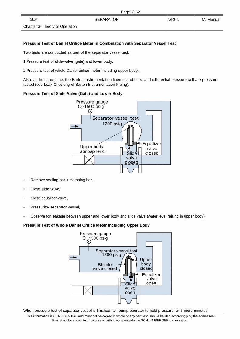
Page :3-62
SEP SEPARATOR SRPC M. Manual
Chapter 3- Theory of Operation
This information is CONFIDENTIAL and must not be copied in whole or any part, and should be filed accordingly by the addressee.It must not be shown to or discussed with anyone outside the SCHLUMBERGER organization.
Pressure Test of Daniel Orifice Meter in Combination with Separator Vessel Test
Two tests are conducted as part of the separator vessel test:
1.Pressure test of slide-valve (gate) and lower body.
2.Pressure test of whole Daniel-orifice-meter including upper body.
Also, at the same time, the Barton instrumentation liners, scrubbers, and differential pressure cell are pressuretested (see Leak Checking of Barton Instrumentation Piping).
Pressure Test of Slide-Valve (Gate) and Lower Body
• Remove sealing bar + clamping bar,
• Close slide valve,
• Close equalizer-valve,
• Pressurize separator vessel,
• Observe for leakage between upper and lower body and slide valve (water level raising in upper body).
Pressure Test of Whole Daniel Orifice Meter Including Upper Body
When pressure test of separator vessel is finished, tell pump operator to hold pressure for 5 more minutes.

Page :3-63
SEP SEPARATOR SRPC M. Manual
Chapter 3- Theory of Operation
This information is CONFIDENTIAL and must not be copied in whole or any part, and should be filed accordingly by the addressee.It must not be shown to or discussed with anyone outside the SCHLUMBERGER organization.

Page :3-64
SEP SEPARATOR SRPC M. Manual
Chapter 3- Theory of Operation
This information is CONFIDENTIAL and must not be copied in whole or any part, and should be filed accordingly by the addressee.It must not be shown to or discussed with anyone outside the SCHLUMBERGER organization.
• Mount sealing bar gasket, sealing bar and clamping bar and close upper body,
• Tighten firmly clamping bar screws,
• Close bleeder valve,
• Slowly open equalizer valve (Keep head away from top of Daniel).
• Open slide-valve (gate).
• Check for leakage around equalizer valve, bleeder valve, grease-gun-stem and sealing bar.
3.1.11.4 Model Identification of Barton Recorder
The most common differential pressure recorder used with our separator is the ITT Barton model 202N forNACE applications. For each 202N instrument a descriptive ID number is assigned that designates the typeand range of installed elements and components.
STRUCTURE OF ID NUMBER
202-N Code DPUCode static
ElementCode Temp.
ElementCode ChartDrive/pen
AAssemblyidentifier
Elements might have been changed out since delivery of the instrument, therefore it is better to individuallycheck the elements.
1.Differential pressure unit, DPU (commonly used DP-199N)
The range of the DPU spring has to be written on the recorder case by the person performing the shopcalibration.
Water Column Code
Standard spring ranges with DP-199N0-50" A0-75" B0-100" C0-150" D0-200"
Other spring ranges are available:
With 3"3/4 Bellows0-20" WC (not NACE)0-400" WC
With 2"1/8 Bellows0-15 psi0-100 psi

Page :3-65
SEP SEPARATOR SRPC M. Manual
Chapter 3- Theory of Operation
This information is CONFIDENTIAL and must not be copied in whole or any part, and should be filed accordingly by the addressee.It must not be shown to or discussed with anyone outside the SCHLUMBERGER organization.
2.Static pressure unit
Identify the range directly by locking at the ID-plate of the static pressure element.
3.Temperature unit
Identify the range directly by locking at the ID-plate of the temperature element.
4.Clock
Switch to 24 hrs operation, wind clock up and put a chart in to see if chart is turning.
5.Pens
Check that the following color arrangement with pens is used.• Blue = Differential pressure
• Red = Static pressure
• Green = Temperature
3.1.11.5 Leak Checking of Barton Instrumentation Piping
Before starting any calibration checks ensure Barton instrumentation piping holds pressure. Perform thesechecks immediately after pressure testing the orifice plate seal of the Daniel.
PREPARATION
• Open two bypass-valves (GMV1, GMV2).
• Close all other valves on manifold.
• Pressurize the system to 100 psig.
• Open two block-valves (GMV5, GMV6).
• Observe differential pressure pen (should be at 0).
• Bleed moisture from system by draining scrubbers and opening vent-valve (GMV3).

Page :3-66
SEP SEPARATOR SRPC M. Manual
Chapter 3- Theory of Operation
This information is CONFIDENTIAL and must not be copied in whole or any part, and should be filed accordingly by the addressee.It must not be shown to or discussed with anyone outside the SCHLUMBERGER organization.
LEAK CHECK
• Close two block valves (GMV5, GMV6) to isolate the instrumentation system.
• Bleed separator vessel to atmospheric.
• Close two bypass valves (GMV1, GMV2).
• Open vent valve GMV3
The two sides of the differential pressure sensing system are now isolated. Any leakage of instrumentationpiping causes a deflection of the differential pressure pen.
• Observe if differential pressure pen deflects from 0.
NOTE – To trace leaks in instrumentation piping, shaving foam has proven to be useful.

Page :3-67
SEP SEPARATOR SRPC M. Manual
Chapter 3- Theory of Operation
This information is CONFIDENTIAL and must not be copied in whole or any part, and should be filed accordingly by the addressee.It must not be shown to or discussed with anyone outside the SCHLUMBERGER organization.
3.1.11.6 Static Pressure Check on Barton Recorder
1.SET UP• Disconnect static pressure sensing liner from Barton recorder and connect dead weight tester directly to
the Bourdon tube inlet port (see ).
• Keep fitting loose and flush the line from DWT to Barton.
• Tighten connection.
2.ZERO CHECK• Place chart into Barton-recorder.
• Check if static pen shows 0 on chart with no pressure applied.
3.CHECK LINEARITY• Apply 50% of FRO of the Bourdon tube nominal pressure range and check if§ pen is reading 50% on chart
§ linkages are squared up (90° angles between linkages)
4.CHECK ANGULARITY• Apply 100% of FRO of Bourdon tube nominal pressure and check if pen shows 100% on chart.
5.ZERO CHECK• Bleed off pressure and physically loosen fitting to make sure no pressure is trapped; check if pens comes
back to 0.

Page :3-68
SEP SEPARATOR SRPC M. Manual
Chapter 3- Theory of Operation
This information is CONFIDENTIAL and must not be copied in whole or any part, and should be filed accordingly by the addressee.It must not be shown to or discussed with anyone outside the SCHLUMBERGER organization.
3.1.11.7 Differential Pressure Checks on Barton Recorder
1.SET UP• Connect the calibration unit consisting of a calibration gauge (reference) and a regulator to GMV3.
(Different calibration gauges and regulators are used which are bought from local suppliers in general).
• Close GMV1 and GMV5.
• Open GMV2.
• Open LP scrubber bleed valve to ensure this side is bled to atmospheric.
2.PURGE LINES• Open drain valve on bottom of HP-scrubber to drain any liquid accumulated in the system by passing air
through regulator.
• Shut off air supply and close drain valve of HP-scrubber.
3.ZERO CHECK• Check that differential pressure pen indicates zero on chart with no pressure applied.
4.CHECK LINEARITY• Apply 50% of differential pressure cell (spring) FRO by reading the calibration gauge.
• Check if pen is reading 50% on chart.
• Check that linkages are squared up (90% angles between linkages, see ).

Page :3-69
SEP SEPARATOR SRPC M. Manual
Chapter 3- Theory of Operation
This information is CONFIDENTIAL and must not be copied in whole or any part, and should be filed accordingly by the addressee.It must not be shown to or discussed with anyone outside the SCHLUMBERGER organization.
5.CHECK ANGULARITY
The importance of the differential pressure measurement requires a five point calibration check to be performed.• Apply 100% of FRO and check if pen stabilizes at 100% on chart.
• Check if differential pressure pen path coincides with the time arc on chart.
• Apply differential pressure in steps of 80%, 60%, 40%, 20% of FRO and check accordance of calibrationgauge reading with chart recorder reading.
6.ZERO CHECK• Bleed off all differential pressure and open drain valve on scrubber.
• Check if differential pressure pen comes back to zero on chart.

Page :3-70
SEP SEPARATOR SRPC M. Manual
Chapter 3- Theory of Operation
This information is CONFIDENTIAL and must not be copied in whole or any part, and should be filed accordingly by the addressee.It must not be shown to or discussed with anyone outside the SCHLUMBERGER organization.
3.2 Run
3.2.1 Separator Operations
3.2.1.1.1 Directing Flow through Separator (Initial)
3.2.1.1.2 Preparation
Vessel
• Separator vessel is empty (both: oil and water compartment).
• All bleed down valves are shut.
INSTRUMENTATION
• Pressure gauge is installed on top of separator.
• Orifice plate holder is removed from Daniel orifice meter and slide-valve (gate) is closed.
• Gas metering instrumentation is isolated from gasline.
• Oil meters are bypassed.
• Sight glass valves are open and in safety position for oil-and water sightglass.
Controllers
• Wizard is set to downstream pressure during the clean-up flow.
• Level-troll is set to middle-level position.
3.2.1.1.3 PROCEDURE
Setup valve positions
• Open separator gas line valve (GASACV is shut).
• Open separator oil line valve (2") (OILACVs are shut).
• Open separator inlet valve, then close bypass.
Establishing vessel pressure and raising liquid level
• Observe raising vessel pressure and GASACV opening.
• Record gasline back pressure downstream of GASACV once separator pressure is established.
• Observe liquid level raising in water sight-glass and estimate liquid flowrate (see Functional Checks onSeparator Sight Glasses).
• Define oil line process-parameters:- Number of burner heads or tank
- 1" or 2" OILACV
• Line up oil line according to above process parameters.

Page :3-71
SEP SEPARATOR SRPC M. Manual
Chapter 3- Theory of Operation
This information is CONFIDENTIAL and must not be copied in whole or any part, and should be filed accordingly by the addressee.It must not be shown to or discussed with anyone outside the SCHLUMBERGER organization.
• Confirmation of presence and height of water weir.

Page :3-72
SEP SEPARATOR SRPC M. Manual
Chapter 3- Theory of Operation
This information is CONFIDENTIAL and must not be copied in whole or any part, and should be filed accordingly by the addressee.It must not be shown to or discussed with anyone outside the SCHLUMBERGER organization.
Establishing liquid level and passing oil to burners or tank
• Adjust liquid level and observe operation of OILACV
• Record oil line back pressure downstream of OILACV once liquid level is established.
• Alter amount of burner heads according to oil line back pressure if necessary or flow to tank.
3.2.1.2 Flowrate Estimation during Filling up the Separator
When flowing to the separator, the time required to fill up the water compartment (known volume) can be usedto estimate the liquid rate. This estimated rate is then used to set up process parameters like the amount ofburner heads to flow to or which OILACV (1" or 2" in) to use. The values given below are calculated for thestandard 1440 psi separator (42" x 10 ft) and should be considered as rough estimation only.
It is strongly recommended to actually measure the volume of the water compartment. This is done in the baseby draining a full water compartment and measure the volume.
That way you can make up your own table for the specific separator in use.
Time to Fill water compartment1 Estimated Flowrate (bbl/d)
30 seconds 96002 minutes 24003 minutes 16001 minute 48004 minutes 12005 minutes 1000
10 minutes 50020 minutes 250
1. Estimated volume of water-compartment = 3.35 bbl 1440 psi 42 in x 10 ft separator

Page :3-73
SEP SEPARATOR SRPC M. Manual
Chapter 3- Theory of Operation
This information is CONFIDENTIAL and must not be copied in whole or any part, and should be filed accordingly by the addressee.It must not be shown to or discussed with anyone outside the SCHLUMBERGER organization.
3.2.1.3 Separator Operations during Choke Changes
When changing chokes our aim is:
• TO REMAIN UNDER CRITICAL FLOW CONDITIONS.
• TO KEEP SEPARATOR IN LINE.
• TO MAINTAIN SEPARATOR CONDITIONS (PRESSURE, LEVEL, TEMPERATURE).
• TO RESTRICT FLUCTUATIONS TO A MINIMUM.
Avoid bypassing the separator vessel which would result in a sudden increase of the oil line back pressurecausing the downstream pressure to rise. If the limit of critical flow is exceeded you will affect Downholeconditions and therefore Downhole gauge data.
Procedure for changing chokes during the main flow periods
• Bypass oil and gas metering instrumentation.
• Estimate change in oil line backpressure due to change of choke and adjust amount of burnerheadsaccordingly.
• Change choke size as required.
• Observe separator conditions as chokes are changed but leave them constant (pressure, level,temperature).
• Observe new backpressures on oil-and gasline and free-travel on oil-and gas ACVs.
• Readjust amount of burnerheads if necessary.
• Check for liquid-carryover in the gasline by bleeding at bottom tap of Daniel orifice meter.
• When separator is stabilized, pass through meters.
3.2.1.4 Separator System Response when Increasing Choke
The following illustration shows you the expected separator system response when increasing the choke size.
Separator vessel conditions (vessel pressure, liquid level, temperature) remain constant before and after thechoke change.

Page :3-74
SEP SEPARATOR SRPC M. Manual
Chapter 3- Theory of Operation
This information is CONFIDENTIAL and must not be copied in whole or any part, and should be filed accordingly by the addressee.It must not be shown to or discussed with anyone outside the SCHLUMBERGER organization.
Possible problems
• If OILACV opens fully after choke change, increase the number of burnerheads to reduce the oil linebackpressure.
• If all burnerheads are already used and the OILACV is fully open, increase the separator pressure to regaincontrolling action of the OILACV.
• If GASACV is fully open, increase the separator pressure to regain controlling action of the GASACV.
In the last two cases the separator pressure had to be increased in order to maintain controlling action of theACVs. This is bad practice and should only be used if there is no other option available.
Try to keep separator conditions constant during the test to be able to compare the results of all flowperiods.
3.2.1.5 Bypassing the Separator when Shutting in a Well
When shutting in a well for a build up following a flow period through the separator, the sequence of valveoperations is critical for the validity of bottomhole pressure data.
3.2.1.5.1 Principle of Operation
NOTE – Always shut in the well first (either Downhole or at surface) and then bypass the separator.
Explanation
Bypassing the separator and flowing the wellstream straight to the burner results in a sudden increase of oilline backpressure which can exceed the limit of critical flow and be reflected in Downhole gauge data.
The figure of "BAD DATA" shows an example where the separator was bypassed before the well was shut in.In this case the system was in critical flow when flowing through the separator but the critical flow conditionwas not fulfilled any more as soon as the separator was bypassed. The obtained pressure data complicate theanalysis of reservoir engineers and should therefore be avoided.

Page :3-75
SEP SEPARATOR SRPC M. Manual
Chapter 3- Theory of Operation
This information is CONFIDENTIAL and must not be copied in whole or any part, and should be filed accordingly by the addressee.It must not be shown to or discussed with anyone outside the SCHLUMBERGER organization.
The figure of "GOOD DATA" shows an example of what you are expected to deliver to the client. A stabilizedbottom hole flowing pressure without disturbance and a sharp shut in response.

Page :3-76
SEP SEPARATOR SRPC M. Manual
Chapter 3- Theory of Operation
This information is CONFIDENTIAL and must not be copied in whole or any part, and should be filed accordingly by the addressee.It must not be shown to or discussed with anyone outside the SCHLUMBERGER organization.
In this case the well was shut prior to bypassing the separator.
Below are listed the sequence of valve operations which are recommended to fulfil the requirements for goodDownhole gauge data.
1.DOWNHOLE SHUT IN• Bypass metering instrumentation on separator.
• Close Downhole tester-valve.
• Wait for clear response at surface indicating that Downhole tester-valve is shut.
For example, drop in wellhead pressure by 200 psi.
• Bypass separator
Since Downhole gauges are now isolated by Downhole tester valve you can safely bypass the separatorwithout affecting the gauge data.
• Shut in well at surface at choke manifold.
It is recommended to bleed the string so that surface shut in pressure is clearly lower than last flowingpressure. That way we are able to confirm the integrity of the Downhole tester-valve at surface during thebuild-up.
• SURFACE SHUT IN
• Bypass metering instrumentation on separator.
• Shut in well at choke-manifold.
• Bypass separator.
3.2.1.6 Inserting an Orifice-Plate under Line Pressure
CAUTION – Never place your head directly above the Daniel orifice meter.
Preparation
Equalize Barton instrumentation before starting any work on the Daniel orifice meter in order not to damage thedifferential pressure cell.

Page :3-77
SEP SEPARATOR SRPC M. Manual
Chapter 3- Theory of Operation
This information is CONFIDENTIAL and must not be copied in whole or any part, and should be filed accordingly by the addressee.It must not be shown to or discussed with anyone outside the SCHLUMBERGER organization.

Page :3-78
SEP SEPARATOR SRPC M. Manual
Chapter 3- Theory of Operation
This information is CONFIDENTIAL and must not be copied in whole or any part, and should be filed accordingly by the addressee.It must not be shown to or discussed with anyone outside the SCHLUMBERGER organization.
Procedure
• Insert plate holder with orifice plate into Daniel upper chamber.
• Lower plate holder below sealing bar gasket level by rotating upper plate carrier shaft clockwise (Don't pushplate holder down too far. Slide valve (gate) can be pushed off its seat and gas line contents will leakthrough slide valve).
• Mount a new sealing bar gasket, sealing and clamping bar and tighten clamping bar screws methodically.Then close bleeder valve.
• Open equalizer valve and observe for leaks.
• Open slide valve (gate) by turning valve shaft clockwise.
• Rotate upper plate carrier shaft clockwise and lower plate carrier until a rotation of lower carrier shaft isobserved.
• Continue lowering plate carrier by rotating lower plate carrier shaft clockwise until further rotation isimpossible (plate is fully down).
• Close slide valve (gate) by rotating slide valve shaft counterclockwise.
• Close equalizing valve.
• Open bleeder valve to bleed pressure in upper chamber and also check if slide valve is holding.
• Reclose bleeder valve.
3.2.1.7 Removing an orifice-plate under line pressure
CAUTION – Never place your head directly above the Daniel orifice meter.
Preparation
Equalize Barton instrumentation before starting any work on the Daniel orifice meter in order not to damage thedifferential pressure cell.

Page :3-79
SEP SEPARATOR SRPC M. Manual
Chapter 3- Theory of Operation
This information is CONFIDENTIAL and must not be copied in whole or any part, and should be filed accordingly by the addressee.It must not be shown to or discussed with anyone outside the SCHLUMBERGER organization.
Procedure
• Make sure bleeder valve is closed.
• Open equalizer valve and check for leaks at sealing bar gasket.
• Open slide valve (gate).
• Rotate lower plate carrier shaft counterclockwise until rotation of upper plate carrier shaft is observed.
• Continue raising plate carrier by rotating upper plate carrier shaft counterclockwise until further rotation isimpossible (plate is fully up).
• Close slide valve (gate).
• Close equalizer valve.
• Open bleeder valve and bleed off pressure (make sure slide valve is not leaking).
• Loosen clamping bar screws by about 2 turns but don't remove the clamping bar itself yet.
• Turn upper plate carrier shaft counterclockwise and lift sealing bar gasket off its seat (To make sure nopressure is trapped).
• Remove clamping bar, then sealing bar and sealing bar gasket.
• Lift plate holder by turning upper plate carrier shaft counterclockwise and check plate for deformation andseal ring.

Page :3-80
SEP SEPARATOR SRPC M. Manual
Chapter 3- Theory of Operation
This information is CONFIDENTIAL and must not be copied in whole or any part, and should be filed accordingly by the addressee.It must not be shown to or discussed with anyone outside the SCHLUMBERGER organization.
3.2.2 Combined Operations
3.2.2.1 Clean Up
3.2.2.1.1 Limiting Factors of Clean Up
The purpose of the clean-up period is to eliminate all foreign fluids such as mud filtrate, completion fluids, etc.,contained in the invaded zone and wellbore so that representative reservoir fluids are produced during the test.
Any flowrate and pressure measurements performed before the well is cleaned up do not show reservoircharacteristics. Therefore a proper clean-up flow is the key requirement for the validity of the whole test.
In the diagram below, the limiting factors show the restrictions in terms of a minimum and a maximum flowratedefining a range of flowrates for the clean up. The minimum required flowrate results from the necessity todischarge all wellbore fluids and fluids around the wellbore. In gas wells the aim is to achieve a sufficient gasvelocity in order to lift fluid within the gas stream up the test-string.
The maximum flowrate during the clean up should be at least as high as any rate during the following flowperiods. This is restricted by the maximum allowed flowrate resulting from coning and sand production but alsoequipment pressure and temperature ratings.
3.2.2.1.2 Main Phases of Clean Up
In general we can divide every clean up period into 3 main phases:
• Phase I: Cushion recovery
• Phase II: Lifting sump fluids and clean up around perforations
• Phase III: Define maximum choke size for test
All three phases are illustrated in the diagram below. Problems occurring in particular during a phase andrecommended checks to be performed are listed in the diagram and explained in the section Check proceduresfor cleanup

Page :3-81
SEP SEPARATOR SRPC M. Manual
Chapter 3- Theory of Operation
This information is CONFIDENTIAL and must not be copied in whole or any part, and should be filed accordingly by the addressee.It must not be shown to or discussed with anyone outside the SCHLUMBERGER organization.
Phase I: Cushion recovery
As already indicated by its name this phase ranges from start of the clean-up period till the cushion iscompletely discharged from the test string and reservoir fluids reach the surface.
The method, how to recover the cushion will mainly depend on the type of cushion used. In case of Nitrogen forexample we bleed off directly to the flare but when liquid cushions are used (water, diesel) the cushion can alsobe discharged to a tank.
The advantage in the tank recovery lies in the ability to estimate volume and flowrate of discharged cushion andtherefore we can monitor the progress of the cushion recovery.
Preferable a surge tank should be used for discharging liquid cushions and extreme care has to be taken not tooverpressurize the tank. (see procedure: Flowing Back a liquid Cushion to the Tank).
Phase II: Lifting sump fluids and clean up around perforations
This phase is the most time consuming part of the clean up. A common problem in this phase is theenvironmental aspect of the operation if a clean-up separator is not available.
Reservoir fluid, water and mud are produced to surface forming an uncombustable mixture and are dischargedat the burner heads.
Under no circumstances should the flow be passed through the separator either to achieve a proper flaringoperation or attempting to measure rates. Mud and solids will settle in the metering lines and plug them or atleast change their performance causing all subsequent readings to be inaccurate.
Phase III: Define maximum choke size for the test
In this phase the maximum choke size for the whole test has to be chosen in order to evaluate if limiting factors(coning, temperature, etc...) restrict the test program.
A well is only cleaned up to the maximum choke size you have been flowing in the clean up period. If for anyreason a bigger choke size is selected during the main flow, the separator has to be bypassed and the well tobe cleaned up at the new choke size.
Figure 151. MAIN PHASES OF CLEAN UP

Page :3-82
SEP SEPARATOR SRPC M. Manual
Chapter 3- Theory of Operation
This information is CONFIDENTIAL and must not be copied in whole or any part, and should be filed accordingly by the addressee.It must not be shown to or discussed with anyone outside the SCHLUMBERGER organization.

Page :3-83
SEP SEPARATOR SRPC M. Manual
Chapter 3- Theory of Operation
This information is CONFIDENTIAL and must not be copied in whole or any part, and should be filed accordingly by the addressee.It must not be shown to or discussed with anyone outside the SCHLUMBERGER organization.
3.2.2.1.3 Flowing Back a liquid Cushion to the Tank
This method is used to measure the amount of cushion volume recovered and to estimate the flowrate duringflowing back the cushion to a tank.
CAUTION – As we recover, the cushion gas breaks out of the following fluid column which forms a gascap butalso migrates into the cushion. Our aim is to recover safely as much cushion as possible with the tank. Specialcare has to be taken not to exceed the gas capacity of the tank.
PROCEDURE
1.Open Downhole tester valve against closed choke manifold and wait until wellhead pressure is stabilized.
2.Check with companyman volume of cushion in the string.
3.Open well at choke manifold adj. choke and beam up as required.
4.Check frequently for choke plugging by:• Observing downstream pressure gauge.
• Bleeding bubble hose at choke box.
• Listening to noise at choke box.
5.If choke plugging occurs, cycle adjustable choke and put back to desired choke size.
6.Check frequently for proper burner operation as you have to be ready to bypass tank at all times• Pilot lights are on.
• Compressor air flowing through atomizers.
• Water screen is on.
7.Take a tank reading every 5 minutes and calculate:• total volume of cushion flowed back.
• average flowrate in 5 min intervals.

Page :3-84
SEP SEPARATOR SRPC M. Manual
Chapter 3- Theory of Operation
This information is CONFIDENTIAL and must not be copied in whole or any part, and should be filed accordingly by the addressee.It must not be shown to or discussed with anyone outside the SCHLUMBERGER organization.
8.Check for presence of gas at surface using following indications• what fraction of the cushion is recovered.
• by how much is the flowrate increasing between 5 min intervals.
• are there any gas bubbles in liquid cylinder when draining bubble hose.
• changing noise at choke box.
• raising downstream pressure.
• change of fluid coming out of bubble hose.
9.Have one man ready at oil manifold to bypass tank.
10.As soon as gas comes to surface or 70% of cushion is recovered, bypass tank and continue clean up toburner or through clean up separator.
11.Read final tank level and calculate total cushion recovered.
Care should be taken during this operation not to blow up the tank, specially if you are using a gauge tank. Thehigher the choke size during this operation the more gas will migrate into the cushion and less gas free cushioncan be recovered. A higher choke size also increases the gas cap and therefore the pressure fluctuations afterbypassing the tank.
3.2.2.1.4 Check procedures for cleanup
CHOKE PLUGGING
Especially the adjustable choke can plug easily due to mud setting between seat and stem.
• INDICATIONS§ WHDCP drops without changing choke size
§ No fluid comes out bubble hose
§ On choke box there is no noticeable noise indicating any flow
§ WHP raises without changing choke size
§ No fluid comes out of burner head (if flowing to burner)
§ No increase of tank level (if flowing to tank)
• PROCEDURE§ Cycle adjustable choke observing WHP and WHDCP and put back to required choke size.
§ If plugging persists change over to equivalent fixed choke and inspect adjustable choke condition.
§ If plugging repeats discuss with companyman the option of increasing choke size.
Choke plugging is most likely to occur after the cushion has been recovered and mud, etc. reaches surfaceduring flowing to the adjustable choke on a small choke size.

Page :3-85
SEP SEPARATOR SRPC M. Manual
Chapter 3- Theory of Operation
This information is CONFIDENTIAL and must not be copied in whole or any part, and should be filed accordingly by the addressee.It must not be shown to or discussed with anyone outside the SCHLUMBERGER organization.
CHOKE CONDITION
Choke condition has to be checked on fixed or adjustable side if there is reason to believe that choke isplugged or damaged. This routine is also followed whenever you change chokes.
• INDICATIONS§ Persistent choke plugging
§ Unusual raise or change of noise on choke box
§ Sand production
• PROCEDURE§ Change over to alternative choke with equivalent size.
§ Isolate choke box closing upstream and downstream valve.
§ Bleed off choke box at bubble hose and leave needle valve wide open.
§ Take out cap and seat and inspect for damage.
§ Reinstall seat and cap.
§ Close needle valve of bubble hose.
DETERMINATION OF CHANGE OF FLUID TYPE
Especially at the beginning of the clean up, it is important to define the fluid type currently produced to observethe change of fluid interfaces as they reach the surface and to determine the time when reservoir fluids are atsurface.
• INDICATION OF CHANGE OF FLUID TYPE§ Change of WHP and WHDCP.
§ Change of noise at choke box.
§ Change of noise of flare (the more gas content the louder).
§ Change of color of flare (a lighter flare with increasing gas content).
DETERMINATION OF FLUID TYPE
• Place outlet of bubble hose into an empty bucket.
• Hold end of bubble hose with one hand and open needle valve slowly.
• Identify fluid according to color, viscosity, smell etc.
• Close needle valve.
DETERMINATION OF GAS CONTENT OF FLUID
• Place outlet of bubble hose into a bucket half filled with fluid.
• Hold end of bubble hose with one hand and open needle valve slowly.
• Watch for gas-bubbles coming to surface of fluid.
• Close needle valve.

Page :3-86
SEP SEPARATOR SRPC M. Manual
Chapter 3- Theory of Operation
This information is CONFIDENTIAL and must not be copied in whole or any part, and should be filed accordingly by the addressee.It must not be shown to or discussed with anyone outside the SCHLUMBERGER organization.

Page :3-87
SEP SEPARATOR SRPC M. Manual
Chapter 3- Theory of Operation
This information is CONFIDENTIAL and must not be copied in whole or any part, and should be filed accordingly by the addressee.It must not be shown to or discussed with anyone outside the SCHLUMBERGER organization.
SLUGGING
Under slugging we understand unloading of liquid slugs of the well in cycles. Slugging usually occurs afterrecovery of the cushion in the second phase of the clean up.
Parts of the cushion and / or sump fluid, mud, etc. join together or slugs in the wellbore which are lifted up likea piston by the following oil / gas.
• INDICATIONS§ Strong cyclic fluctuations of WHP (cycles 1 - 10 min).
§ Change of noise at choke box as slugs come up.
§ Rapid changes of BSW (depends on slug composition).
§ Cycling discharge at burners.
• PROCEDURE§ Leave same choke size or choke up to help discharge.
If a well is slugging, it means that the fluid velocity in the string is not enough to unload fluids continuously. It isnot recommended to choke back at this stage.
HYDRATES
Hydrates are a chemical compound between hydrocarbon gas and water. They are most likely to occur inPhase II of the clean up.
§ FACTORS PROMOTING HYDRATE FORMATION§ Presence of heavy components of hydrocarbon gas (ethane, propane) → higher gas gravity.
§ Presence of water slugs during clean up.
§ CO2 and H2S content.
§ Pressure pulsations (during slugging).
§ The higher the pressure the more likely hydrates are forming.
§ Excessive amount of crossovers, bends, elbows (rig up).
§ Pressure drop across chokes.
§ Low surface temperature.

Page :3-88
SEP SEPARATOR SRPC M. Manual
Chapter 3- Theory of Operation
This information is CONFIDENTIAL and must not be copied in whole or any part, and should be filed accordingly by the addressee.It must not be shown to or discussed with anyone outside the SCHLUMBERGER organization.
• HYDRATE PREVENTION§ Injection of methanol upstream of choke manifold, Flowhead, lubricator valve and EZ-Tree or EZ-Valve.
§ Using heater choke or steam exchanger choke.
§ Heat choke box and downstream lines with steam.
§ Select biggest possible plunger in TEXSTEAM PUMP to enable injection at WHP (see chart FOH 1).
• INDICATIONS§ When bleeding bubble hose line blocks and snow-like particles shoot out.
§ Adjustable choke is hard to cycle and tends to plug.
§ Valves are difficult to operate they do not fully close (count number of turns).
§ Line blockage, WHDCP comes up.
• PROCEDURE§ Close next valve upstream where blockage occurs.
§ Bleed off pressure.
§ Heat up lines.
§ Inject Methanol.
Gas wells or high GOR wells during clean up Phase II with slugs of water coming up is a candidate forhydrates.
For charts consult FOHI section 7.
WHDCP-TRENDS DURING CLEAN UP
As wellhead pressure stabilizes also WHDCP should become fairly stable towards the end of the clean up.
WHT-TRENDS
Wellhead temperature will increase with the influx of hot reservoir fluids and eventually stabilize at a particularchoke size. Stabilized WHT is dependent on flowrate. In case of low and medium GOR wells WHT in generalraises with flowrate.
In case of high GOR wells, gas wells and gas condensate wells this trend is only followed up to a certainflowrate. Especially at high flowrate gas expansion in the test string results in a dropping WHT with increasingflowrate.
The stabilization of the WHT takes generally longer than the stabilization of the WHP.
SAND PRODUCTION
Every formation has a maximum drawdown exceeding of which results in a break down of the formation andsand production.
• INDICATIONS AT SURFACE§ Increase of BSW.
§ Sanddec if available.
§ Cut choke seats and stems.

Page :3-89
SEP SEPARATOR SRPC M. Manual
Chapter 3- Theory of Operation
This information is CONFIDENTIAL and must not be copied in whole or any part, and should be filed accordingly by the addressee.It must not be shown to or discussed with anyone outside the SCHLUMBERGER organization.
§ Increase of noise at choke box.
§ Raise of WHDCP at unchanged choke size.
§ Drop of WHP at unchanged choke size.
• PROCEDURES§ Choke back immediately and check if sand production persists.
It is one of the objectives of the clean up phase to check that at maximum selected choke size there is nosand production.
• WATER CONING
Water coning is the production of mobile formation water coming from below the oil water contact in thereservoir.
The water cut (percentage of water produced) is dependant of the drawdown.
• To determine if water coning exists§ Measure the stabilized BSW at different choke sizes.
If the stabilized BSW's increase with the choke size then water coning could be a problem.
Be careful not to misinterpret your results.
As you are choking up liquid from sump and formation gets lifted up and therefore the BSW will raise. Youhave to wait till this transition is over and then take the BSW when the well is stabilized.
WHP-TRENDS DURING CLEAN UP
Figure 154. TYPICAL WHP-RESPONSE DURING A CLEAN UP
The WHP-trend is mainly observed in Phase III of the clean up. This final phase of the clean up is mainly usedto refine test planning of the following stable flow periods and examine problems at maximum choke size as thewell is still cleaning up mainly reservoir damages around wellbore with increased radius of investigation.
• WE WANT TO FIND OUT§ What is the stabilized WHP and corresponding WHDCP at various given choke sizes?
§ How fast does the WHP stabilize after a choke change?
§ How much does the BSW go up after a choke change?
§ How fast does the BSW stabilize at an acceptable level after the choke change?

Page :3-90
SEP SEPARATOR SRPC M. Manual
Chapter 3- Theory of Operation
This information is CONFIDENTIAL and must not be copied in whole or any part, and should be filed accordingly by the addressee.It must not be shown to or discussed with anyone outside the SCHLUMBERGER organization.
Definition of stable flow dependent on reservoir conditions
The question if a well is stable is very much dependant on the type of reservoir and cannot be answered ingeneral. At stable flow conditions the radius of investigation has proceeded past near well bore effects and is inthe undamaged reservoir or has reached a reservoir limit in case of small reservoirs.
Case 1: low to medium GOR oil well (classical oil well)
This type stabilizes relatively fast in comparison with other wells. A raising WHP means that the well is not yetclean. Especially low productivity wells can take a long time to clean up.
You have to wait till the pressure at the wellhead is either constant or slightly dropping to be sure that the wellis clean.
Case 2: High GOR and gas wells
These type of wells take in general longer to clean up and to stabilize. Choking up usually results in lifting moreliquids and especially with gas wells it is important to clean up at the maximum choke size you will ever flowthis well during the following flow periods. Similar to low or medium GOR wells you have to wait for constant ordropping wellhead pressure to terminate the clean up.
Case 3: Condensate wells
To achieve a stabilized wellhead pressure with condensate wells is sometimes impossible since thecomposition of the produced fluid can change with the choke size.
Liquid fall out in the reservoir at high drawdowns can cause the wellhead pressure to raise with bigger chokesizes.
The volatile condensate-gas mixture in the string is also one cause for persistent wellhead pressurefluctuations.
3.2.2.2 Test Flow
3.2.2.2.1 Test Flow through Separator
The test flow is a short flow period following the clean up flow during which the well stream is passed throughthe separator preferably at the biggest choke size you intend to flow on this test. During this period allimportant process parameters are evaluated in order to create a test strategy. This requires a great deal ofplanning ahead and to foresee operational problems based on parameters measured during the test flow. Thefinal test strategy includes detailed operational decisions for the whole test (all flow periods), which are listedhere after.
Main decisions of the test strategy
1.Separator operating conditions for the whole test (p,T).
2.Amount of burner heads used for each flowperiod or flow to the tank.
3.Which flowperiods require the use of flowrestrictors.
4.Which flowperiods require central gas injection into the oil line.
5.Which flowperiods can we flow to the tank.

Page :3-91
SEP SEPARATOR SRPC M. Manual
Chapter 3- Theory of Operation
This information is CONFIDENTIAL and must not be copied in whole or any part, and should be filed accordingly by the addressee.It must not be shown to or discussed with anyone outside the SCHLUMBERGER organization.
The test strategy has to fulfill each of the following requirements in all flowperiods:
• The separator operating conditions optimize liquid recovery under given conditions.
See Operating Guidelines for Test Separators Dependant on Different Reservoir Fluid Types.
• The atomizer back pressure is always above the environmental limit of 200 psi (or flow to the tank).
See Burner Operations Summary.
• All used ACVs are operating in controlling action during each flowperiod in order to guarantee properseparator operation.
See How the system Works Together (initial setup).
• The well is within critical flow at all times.
See Procedure to Check for Critical Flow Condition.
• The separator operates within its gas and liquid capacity during all flow periods.
See Verification of Separator Capacities.
• Equipment operational limits are not exceeded.
See Checkprocedure for Flowing to a Tank.
3.2.2.2.2 Test Flow through Separator Procedure

Page :3-92
SEP SEPARATOR SRPC M. Manual
Chapter 3- Theory of Operation
This information is CONFIDENTIAL and must not be copied in whole or any part, and should be filed accordingly by the addressee.It must not be shown to or discussed with anyone outside the SCHLUMBERGER organization.

Page :3-93
SEP SEPARATOR SRPC M. Manual
Chapter 3- Theory of Operation
This information is CONFIDENTIAL and must not be copied in whole or any part, and should be filed accordingly by the addressee.It must not be shown to or discussed with anyone outside the SCHLUMBERGER organization.
3.2.2.2.3 Procedure to Check for Critical Flow Condition
During well-testing we apply the principle of critical flow which means that pressure fluctuations downstream ofthe choke do not affect the pressure upstream of the choke.
According to general rules (FOHI) critical flow exists if the following conditions are met:
FOR GAS WELLS :DOWNSTREAM PRESSURE <0.5XUPSTREAM PRESSURE
FOR OIL WELLS :DOWNSTREAM PRESSURE <0.6XUPSTREAM PRESSURE
But above guidelines are only approximations and vary with the type of fluid and the GOR. If you approach thelimit of critical flow it is advisable to actually determine the limit of critical flow with the following procedure.
• Ensure wellhead pressure is stabilized.
• Bring up separator pressure gradually in steps and wait for stabilization after each step.
• At the same time monitor wellhead pressure at the choke manifold using the dead weight tester and thewellhead downstream pressure using a Bourdon tube gauge.
• As long as critical flow exists separator pressure and wellhead downstream pressure both increase byabout the same amount but wellhead pressure remains constant (see diagrams below).
• When wellhead pressure starts to raise you have reached the limit of critical flow. Note the correspondingwellhead downstream pressure for this limit.

Page :3-94
SEP SEPARATOR SRPC M. Manual
Chapter 3- Theory of Operation
This information is CONFIDENTIAL and must not be copied in whole or any part, and should be filed accordingly by the addressee.It must not be shown to or discussed with anyone outside the SCHLUMBERGER organization.
3.2.2.2.4 Burner Operation Planning
The aim of this procedure is to plan ahead how many burner heads must be used for each flowperiod on allrequested choke sizes.
Select number of burner heads according to 2 criteria:
• MINIMUM BACKPRESSURE REQUIRED FOR EFFICIENT BURNING (environmental limit).
• MAXIMUM BACKPRESSURE LIMITS THE OPERATING RANGE OF THE SEPARATOR (operational limit).
This diagram illustrates how to estimate the operating pressures for the burner immediately after the clean up.
The results enables you to predict:
• WHAT ARE THE BURNER BACKPRESSURES AT EACH CHOKE SIZE DURING FLOWING THROUGHTHE SEPARATOR (MAIN FLOWS)?
• WHICH CHOKE SIZES ALLOW AN EFFICIENT BURNING OPERATION AT A CERTAIN BURNER HEADCONFIGURATION (ABOVE ENVIRONMENTAL LIMIT)?
• AT WHICH CHOKE SIZES DO I HAVE TO CHANGE THE NUMBER OF BURNER HEADS TO REMAINABOVE THE ENVIRONMENTAL LIMIT, THUS AVOIDING POLLUTION?
• HOW DOES THE REDUCTION OF BURNER HEADS AFFECT THE OPERATING RANGE OF THESEPARATOR?
• WILL IT BE POSSIBLE TO RUN THE SEPARATOR AT THE SAME OPERATING PRESSURE FOR ALLDESIRED CHOKE SIZES DURING THE MAIN FLOW?
1.Draw x and y axis an mark measured wellhead downchoke pressures of cleanup (bypassed separator) ona linear scale on y-axis.

Page :3-95
SEP SEPARATOR SRPC M. Manual
Chapter 3- Theory of Operation
This information is CONFIDENTIAL and must not be copied in whole or any part, and should be filed accordingly by the addressee.It must not be shown to or discussed with anyone outside the SCHLUMBERGER organization.
2.Draw a 45° line through the center and draw operating points on this line. Mark choke sizes on x-axis.
3.Mark burner backpressure from test flow through separator (BURNP4) at specific choke size and draw a linefrom this point through the origin.
4.Cross this new line with the choke lines for the main flow and read predicted backpressures on y-axis(BURNP*)
5.Draw lines for environmental and separator operating limits. If one operating point lies below environmentallimit, reduce by one burner head.
To obtain the new operating pressure multiply by K• K = 2 (if switching from 2 → 1 heads)
• K = 1.33 (if switching from 3 → 2 heads)
• K = 3 (if switching from 3 → 1 heads)
If you flow already on one head, you have to check if you can flow to a tank.

Page :3-96
SEP SEPARATOR SRPC M. Manual
Chapter 3- Theory of Operation
This information is CONFIDENTIAL and must not be copied in whole or any part, and should be filed accordingly by the addressee.It must not be shown to or discussed with anyone outside the SCHLUMBERGER organization.
3.2.2.2.5 How the system Works Together (initial setup)
In following illustration the separator vessel with its automatic control valves (ACVs) and the burner with avarying amount of heads is considered to be a "system." How the change of one parameter affects othersystem parameters is illustrated with two examples.
EXAMPLE 1: CLOSING ONE BURNERHEAD CAUSES:
• an increase of oil line backpressure
• further opening of the acting OILACV.
EXAMPLE 2: DECREASE OF SEPARATOR PRESSURE
• decreases the oil line backpressure (decrease of GOR2)
• opens OILACV (less pressure drop across ACV)
• increases the gasline backpressure (higher gas velocity)
• opens GASACV (less pressure drop across ACV)