Embed Size (px)
Citation preview

1
CHAPTER 28 Advanced UCS, Views, Text, and Dimensions in 3D
Learning Objectives In this chapter, we complete the design toolbox and expand on your ability to use surfaces of objects to create new shapes. We cover • Advanced UCS • UCS • World • UCS previous • Face UCS • Object • View • Origin • Z-axis vector • 3 Point • X, Y, Z • Apply • Named UCS • Views • Text and dimensioning in 3D
By the end of this chapter, you will be able to create designs regardless of the surface of orientation. Estimated time for completion of this chapter: 1 hour.

2
28.1 INTRODUCTION TO ADVANCED UCS, VIEWS, TEXT, AND DIMENSIONS IN 3D This chapter begins with some additional tools needed to effectively work in 3D space. Advanced UCS refers to additional functionality with the Universal Coordinate Symbol. This symbol is not static in regard to the surfaces with which you work. You can relocate it to a more convenient plane as you see fit to create new design features more effectively.
Once we cover this new functionality, we do a quick introduction to saving views so you can come back and reuse them. This is important in complex designs, where you do not want to continually “reinvent the wheel” after you find new views to work more effectively. Finally, we discuss using text and dimensions in 3D space. Although this is not necessarily different from 2D space, the orientation may throw you off, and some tips and tricks are needed. 28.2 ADVANCED UCS So far the Universal Coordinate System (UCS) icon has been sitting in the background, acting as a reference point when we need to rotate something about an axis or mirror something about a plane. The icon itself is also rotated occasionally, when we need to draw into another plane. This is all good, but we can make the icon work even harder for us and add some more usefulness to its repertoire. To investigate it further, bring up UCS’s two toolbars: UCS and UCS II, as seen in Figure 28.1. We cover these additional icons (and of course their typed, cascading menu, and Ribbon counterparts).
FIGURE 28.1 UCS and UCS II toolbars.
Most of the new commands have something to do with aligning the UCS icon with chosen geometry. This is the central theme in learning UCS’s new features. Why is such alignment important? Because this gives you a new “platform” off which to work. Suppose you have an object that is leaning in some direction and you need to draw something else that sits on it. You can draw this new object and rotate it into position, but a better approach is to right away align yourself with the tilted surface and use that as a base from which to draw. All this should tie in with the fundamental theory presented way back in Chapter 21 concerning drawing planes and their rotation. Let us jump right in, and you will clearly see what we are talking about very soon.
First of all, though, we need something on which to practice. The various UCS functions are best understood by just trying them out, so we use the shape in Figure 28.2 for all UCS demonstrations. Draw a rectangle of any size and extrude it, then rotate3D it some value (perhaps 20°) and mirror3D it for symmetry. The result in the SW Isometric view is shown in Figure 28.2.
FIGURE 28.2 Basic shapes for UCS practice. UCS This first tool presents many options but is primarily used for aligning the UCS via several clicks of the mouse.

3
Step 1. Start the UCS command via any of the preceding methods. • AutoCAD says: Specify origin of UCS or
[Face/NAmed/OBject/Previous/View/World/X/Y/Z/ZAxis] <World>: Step 2. Click somewhere on the object to locate the origin (always using OSNAPs).
• AutoCAD says: Specify point on X-axis or <Accept>: Step 3. Here, you can just press Enter, but if you click on another point, the positive X axis of the UCS icon passes through that point.
• AutoCAD says: Specify point on the XY plane or <Accept>: Step 4. Here, you can again press Enter, but if you click on a third and final point somewhere on the object the Y axis passes through
it. Notice how the UCS is now aligned to the points you indicated. We revisit this a bit later with the Object and 3 Point
options. The basic UCS command can also be used to rotate the UCS around any of the axes, although there are actually dedicated icons, as we explore soon. World This next tool should be a familiar one, as it “resets” the UCS icon and was mentioned in earlier chapters. The result is that the UCS is returned to the World view from whatever configuration it may have been in previously. Try it out via the following methods.
UCS Previous This next tool simply returns you to whatever UCS configuration you had previously. It is quite useful if you are using just two settings and need to toggle quickly back and forth. Try it out via the following methods.
Face UCS This next tool is one of two very important alignment tools (the other being 3 Point) that are the core of this section on advanced UCS. Here, you can align your UCS to any face on the screen as long as it is flat. The major advantage here, of course, is that you do not need to know the angle of this face.

4
Step 1. Start the command via any of the preceding methods. • AutoCAD says:
Current ucs name: *NO NAME* Specify origin of UCS or [Face/NAmed/OBject/Previous/View/World/X/Y/Z/ZAxis]<World>: _fa Select face of solid object:
Step 2. Click on any face to which you need to align, and the face is highlighted. • AutoCAD says: Enter an option [Next/Xflip/Yflip] <accept>:
You can easily change the direction of the UCS icon while keeping the 0,0,0 origin in one spot by using the Xflip, Yflip, or
Next options before pressing Enter to accept. Object This next tool is an interesting variation on Face UCS. Here, you can select almost any object and the UCS icon aligns itself to that object in various preset ways. With an arc or circle, the alignment is to the center; with a line, it is a point closest to where you clicked; and so forth.
A full listing of how it reacts is in the Help files. In Figure 28.3, we see the UCS icon aligned to a few of these objects.
FIGURE 28.3 Object UCS alignment. View This next UCS tool establishes a new coordinate system with the XY plane perpendicular to your viewing direction (parallel to your screen).
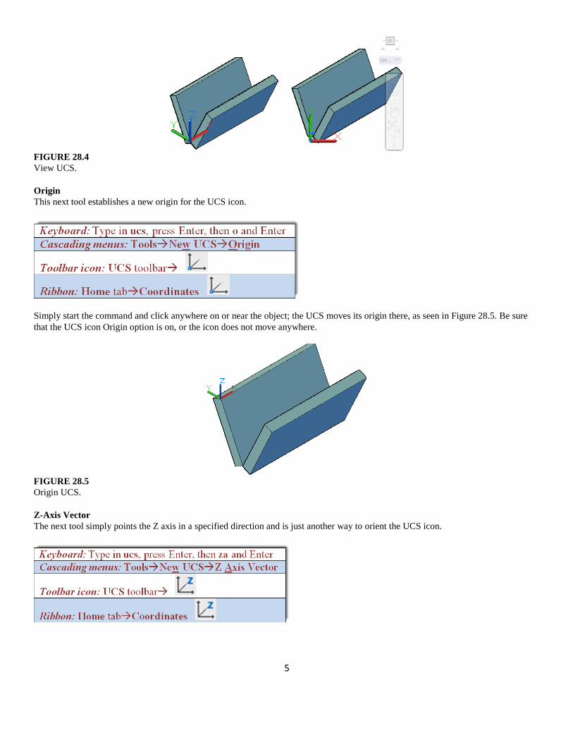
This is equivalent to going to the Top View while still in 3D, as seen in the before and after screen shots of Figure 28.4. This technique probably will not be used too often but is the only way to accomplish this if needed.
5
FIGURE 28.4 View UCS. Origin This next tool establishes a new origin for the UCS icon.
Simply start the command and click anywhere on or near the object; the UCS moves its origin there, as seen in Figure 28.5. Be sure that the UCS icon Origin option is on, or the icon does not move anywhere.
FIGURE 28.5 Origin UCS. Z-Axis Vector The next tool simply points the Z axis in a specified direction and is just another way to orient the UCS icon.

6
3 Point This tool is the other extremely useful orientation tool (along with Face UCS). It works on the concept of three points being used to indicate a plane. We present a full demonstration of its use. This demonstration also is relevant to the Face UCS method, as it also orients the UCS to a plane, although in a different way.
Step 1. Start the command via any of the preceding methods.
• AutoCAD says: Specify origin of UCS or [Face/NAmed/OBject/Previous/View/World/X/Y/Z/ZAxis] <World>: _3 Specify new origin point <0,0,0>:
Step 2. Select the three points in consecutive order to define a plane, as seen in Figure 28.6. • With each click, AutoCAD says:
Specify point on positive portion of X-axis <1.00,0.00,0.00>: Specify point on positive-Y portion of the UCS XY plane 0.00,1.00,0.00>
FIGURE 28.6 Refining 3-Point UCS.
When done, the crosshairs and the UCS icon align themselves with the face defined by the three clicks, as seen in Figure 28.7.
FIGURE 28.7 3-Point UCS.

7
You can now easily draw something based on that surface, as seen in Figure 28.8. Performing the same 3-Point alignment and extrusion on the front surface, we have what is shown in Figure 28.9.
FIGURE 28.8 3-Point UCS, extrusion 1.
FIGURE 28.9 3-Point UCS, extrusion 2.
Note that, as mentioned before, Face UCS works the same way, except that you are just selecting the entire face, not defining it as with 3 Point. But, once you establish the new UCS orientation, proceed in the same manner to create new geometry. X, Y, and Z These tools are simply icons for the familiar UCS rotation you learned about in the first few chapters of Level 3. Simply press the icons instead of typing in the UCS planes, then enter the angle for the rotation. That is all you need to do, and the UCS rotates accordingly.
Taking a look next at the UCS II toolbar, we examine two icons, the Named UCS and the drop-down window next to it. The first icon (UCS) is the same as the one on the previous main UCS toolbar, and we do not go over it again.

8
Named UCS If you are going to spend some time with a UCS configured in a certain useful way, you may want to save it in case you need it again. AutoCAD allows you to save as many custom UCS presets as you want. To save a view, do the following:
Step 1. Type in UCS and press Enter.
• AutoCAD says: Specify origin of UCS or [Face/NAmed/OBject/Previous/View/World/X/Y/Z/ZAxis]<World>:
Step 2. Type in save and press Enter. The Save option does not appear in the preceding menu, but it works. • AutoCAD says: Enter name to save current UCS or [?]
Step 3. Enter a name for your view, which in this case is just a generic MyView, and press Enter.
The new view is now in AutoCAD’s memory, saved for future use. It can be found in the UCS dialog box, which is described next.
The dialog box (Figure 28.10) can be called up via any of the preceding methods. Notice the presence of the highlighted My_View UCS setting. You can go to other settings and always go back to it later.
FIGURE 28.10 Named UCS.
The UCS setting also appears in the toolbar drop-down menu, as seen in Figure 28.11. This drop-down menu is a convenient way to quickly access not only your custom UCS settings but also the preset ones, including World and Previous.
FIGURE 28.11 Named UCS toolbar drop-down menu.

9
28.3 VIEWS AND VIEW MANAGER In a closely related topic to saving preset UCS views, you can also save general views of your design. This is a very convenient tool if you find a good view with which to work and may want to come back to later. The views are saved and managed through the View Manager dialog box. Access the command through any of the following methods:
You then see the dialog box in Figure 28.12. Press the New… button and the New View/Shot Properties dialog box appears, as seen in Figure 28.13. We are not concerned with the Shot Properties tab for now, so just focus on the View Properties tab. Enter a descriptive view name in the first field and press OK. The name then appears in the View Manager. To retrieve the view, just bring up the View Manager again and double-click on the view you want retrieved.
FIGURE 28.12 View Manager. 28.4 TEXT AND DIMENSIONS IN 3D Creating text and dimensions in 3D is not necessarily any different than in 2D; you just use the standard text, mtext, or ddim commands. However, placing them correctly takes some practice because, in 3D, what is up or down is not always clear. You have to pay very close attention to what plane you are on and which way is “up”; otherwise, the dimensions and text appear in the wrong place or the text is inverted. Let us run through a few examples. In each of these cases, pay close attention to everything shown, such as the position of the UCS icon (and the associated crosshairs), as well as the positioning of the dimension and text.
The easiest case is to use the standard World UCS view (SW Isometric) that you are accustomed to in this course. If the Z axis is pointed up, then the dimensions and text come out as shown in Figure 28.14.

10
FIGURE 28.13 New View/Shot Properties.
FIGURE 28.14 3D dimensions and text, Example 1.
Now, what would happen if we reversed the orientation of the Z axis and it faced down instead? As Figure 28.15 shows, if we attempt to then add dimensions and text (horizontal or vertical), we are faced with a complete reversal and mirror imaging of the text and dims, which is not the desired outcome.
FIGURE 28.15 3D dimensions and text, Example 2.

11
As this example shows, you have to be very careful about flipping the UCS icon around when dimensioning, as the results may be unpredictable (or at least seem that way). What happens in this example is that you are writing on the other side of the face. So, how do we add dimensions along the Z axis? The next example addresses this.
Let us bring the Z axis back to World view and rotate the UCS icon 90° along the X axis, as seen in Figure 28.16. Notice the effect this has on horizontal and vertical dimensions.
FIGURE 28.16 3D dimensions and text, Example 3.
With these two UCS settings you should be able to dimension just about anything, as the dimensioned cube in Figure 28.17 indicates, although do not be surprised to run into some difficulties if you are dealing with complex rotated surfaces.
FIGURE 28.17 3D dimensioned cube. SUMMARY You should understand and know how to use the following concepts and commands before moving on to Chapter 29: • Advanced UCS • UCS • World • UCS previous • Face UCS • Object • View • Origin • Z-axis vector • 3 point • X, Y, Z • Apply • Named UCS • View • Text and dimensioning in 3D

12
REVIEW QUESTIONS Answer the following based on what you learned in this chapter: 1. List all 13 advanced UCS functions and what they do. 2. What are views useful for? EXERCISE 1. Create the following fictional 3D suspension and tire model. A breakdown of the parts is shown for clarity, along with hints, but
you still need to know the details of creating each part. Some sizing is given, but the focus is on the commands. Use layers. (Difficulty level: Advanced; Time to completion: 1–2 hours.)
Step 1. Create the tire and rim via plines using the basic sizing as shown. Revolve both around the given centerline 360° for the final
shapes shown.
Step 2. The strut is two sets of extruded circles. The coil spring is a helix and was demonstrated in previous chapters. You can choose which method you want to use. The axle is a 50" long, 3" diameter extruded cylinder.

13
Step 3. The control arms are sweep or path extrusions, your choice. The cylinders are extrusions. For the axle boot, you need to use revolve. The back panel is a 28"×13"×2" extrusion.
Step 4. The disk brake requires extrusion, subtraction, 3Darray, and other commands. It has a 10" diameter. Size the rest from that. The panel is about 12"×8"×1".
14
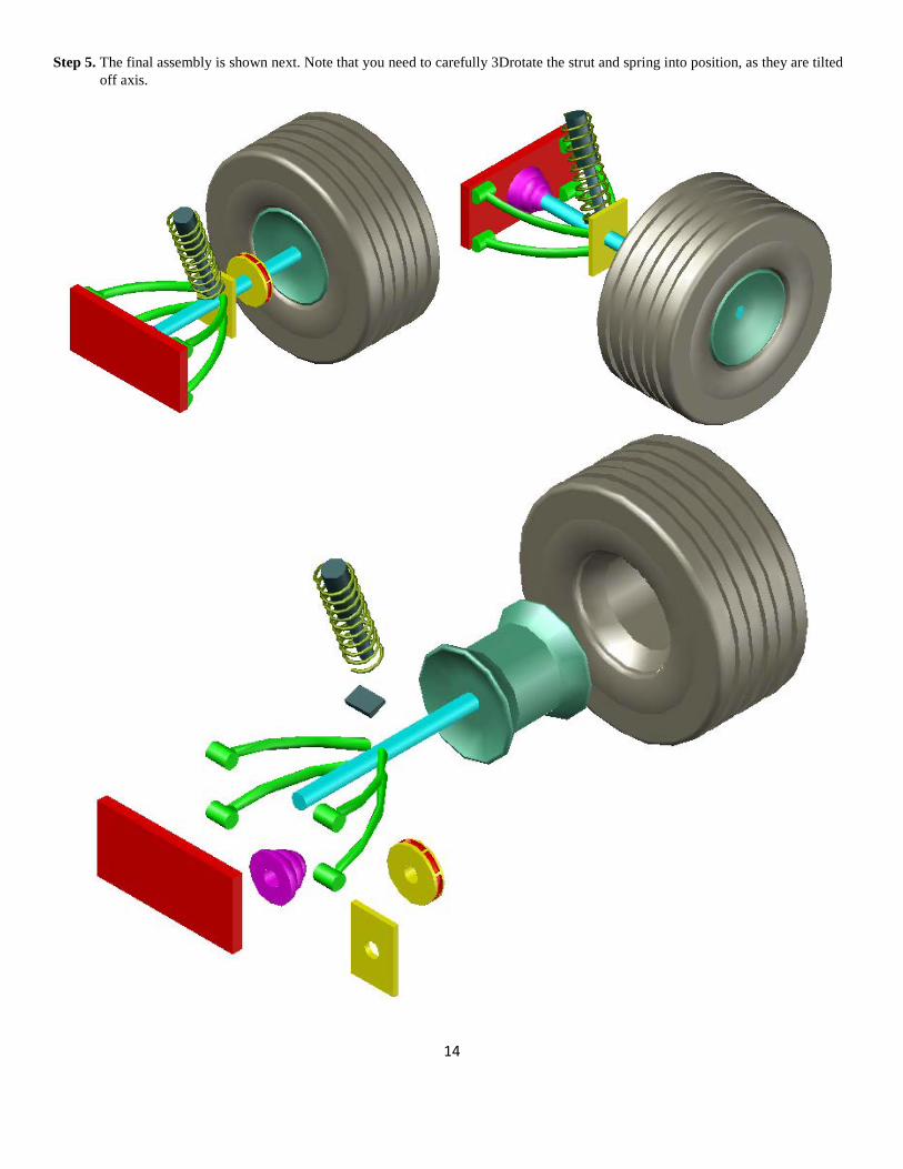
Step 5. The final assembly is shown next. Note that you need to carefully 3Drotate the strut and spring into position, as they are tilted off axis.


![Zggh]hPH>new.groteck.ru/images/catalog/40429/9deec18637ee6ecbb5a6ae0a1… · UCS 6200 Series Fabric Interconnect UCS Manager UCS C240 M3/M4 Series Rack Server UCS Integrated Infrastructure](https://img.dokumen.tips/doc/110x75/5fcc7e22130a463bbb0b3c57/zgghhphnew-ucs-6200-series-fabric-interconnect-ucs-manager-ucs-c240-m3m4.jpg)