Embed Size (px)
Citation preview

Chapter 25 Wave Optics – Lecture 20
25.1 Coherence and Conditions for Interference
25.2 The Michelson Interferometer
25.3 Thin-Film Interference
25.4 Light through a Single-Slit: Qualitative Behavior
25.5 Double-Slit Interference: Young’s Experiment
25.6 Single-Slit Diffraction: Interference of Light from a Single
Slit
25.7 Diffraction Gratings
25.8 Optical Resolution and Rayleigh Criterion

Young’s Double-Slit Experiment
• Light is incident onto two narrow
slits and after passing through
them strikes a screen
• When the two slits are both very
narrow, each slit acts as a
simple point source of outgoing
new spherical waves
Section 25.5
• The light intensity on the screen shows an interference
pattern showing conclusively that light is a wave
• Experiment was first carried out by Thomas Young
around 1800

Young’s Experiment, final
• Assume the slits are very narrow
• According the Huygen’s principle,
each slit acts as a simple source
with circular wave fronts as
viewed from above
• The light intensity on the screen
alternates between bright and
dark as you move along the
screen
• These areas correspond to
regions of constructive
interference and destructive
interference Section 25.5

Double Slit Analysis
• Need to determine the
path length between
each slit and the screen
• Assume W is very large
• If the slits are separated
by a distance d, then
the difference in length
between the paths of
the two rays is
ΔL = d sin θ
Section 25.5

Double Slit Analysis, cont.
• If ΔL is equal to an integral number of complete
wavelengths, then the waves will be in phase when
they strike the screen
• The interference will be constructive
• The light intensity will be large (bright fringes)
d sin θ = m λ m = 0, ±1, ±2, …
• If ΔL is equal to a half number of complete
wavelengths, then the waves will not be in phase
when they strike the screen
• The interference will be destructive
• The light intensity will be zero (dark fringes)
d sin θ = (m + ½) λ m = 0, ±1, ±2, …
Section 25.5
ΔL = d sin θ

Double-Slit Intensity Pattern
• The angle θ varies as
you move along the
screen
• Each bright fringe
corresponds to a
different value of m
• Negative values of m
indicate that the path to
those points on the
screen from the lower
slit is shorter than the
path from the upper slit
Section 25.5

Spacing Between Slits
• Notation:
• d is the distance between the slits
• W is the distance between the slits and the screen
• h is the distance between the adjacent bright fringes
• For m = 1,
• Since the angle is very small,
• sin θ ~ θ and θ ~ λ/d
• Between m = 0 and m = 1,
h = W tan θ
• For small angles, tan θ ~ θ and sin θ ~ θ
• Using the approximations, h = W θ = W λ / d
Section 25.5
sind

Interference with Monochromatic Light
• The conditions for interference state that the
interfering waves must have the same frequency
• This means they must have the same wavelength
• Light with a single frequency is called
monochromatic (one color)
• Light sources with a variety of wavelengths are
generally not useful for double-slit interference
experiments
• The bright and dark fringes may overlap or the total
pattern may be a “washed out” sum of bright and dark
regions
• No bright or dark fringes will be visible
Section 25.5

Single-Slit Interference
• Slits may be narrow
enough to exhibit
diffraction but not so
narrow that they can be
treated as a single point
source of waves
• Assume the single slit
has a width, w
• Light is diffracted as it
passes through the slit
and then propagates to
the screen
Section 25.6

Single-Slit Analysis
• The key to the calculation of
where the fringes occur is
Huygen’s principle
• All points across the slit act
as wave sources
• These different waves
interfere at the screen
• For analysis, divide the slit
into two parts
• Detailed analysis is given
in the supplemental slides
Section 25.6

Single-Slit Fringe Locations
• Destructive interference
will produce a dark fringe
• Detailed analysis is
given in the
supplemental slides
Section 25.6
• Conditions for destructive interference are
w sin θ = ±m λ m = 1, 2, 3, …
• The negative sign will correspond to a fringe below the
center of the screen

Single-Slit – Central Maximum
• The full angular width of the central bright fringe is
θ = 2 λ / w (from w sin θ = ±m λ m = 1, 2, 3, … )
• If the slit is much wider than the wavelength, the light
beam essentially passes straight through the slit with
almost no effect from diffraction
Section 25.6
• Conditions for destructive
interference are
w sin θ = ±m λ
m = 1, 2, 3, …
• Detailed analysis is
given in the
supplemental slides

Double-Slit Interference with Wide Slits
• When the slits of a
double-slit experiment
are not extremely
narrow, the single-slit
diffraction pattern
produced by each sit is
combined with the
sinusoidal double-slit
interference pattern
• A full calculation of the
intensity pattern is very
complicated (see the
attached supplemental
ppt slides)
Section 25.6
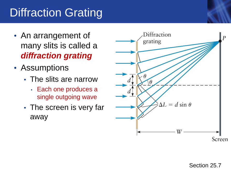
Diffraction Grating
• An arrangement of
many slits is called a
diffraction grating
• Assumptions
• The slits are narrow
• Each one produces a
single outgoing wave
• The screen is very far
away
Section 25.7
Diffraction Grating, cont.
• Since the screen is far away, the rays striking the
screen are approximately parallel
• All make an angle θ with the horizontal axis
• If the slit-to-slit spacing is d, then the path length
difference for the rays from two adjacent slits is
ΔL = d sin θ
• If ΔL is equal to an integral number of wavelengths,
constructive interference occurs
• For a bright fringe, d sin θ = m m = 0, ±1, ±2,
…
Section 25.7
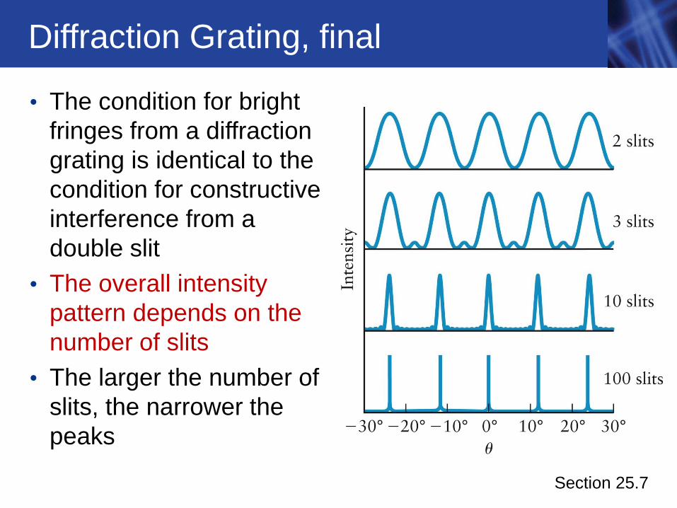
Diffraction Grating, final
• The condition for bright
fringes from a diffraction
grating is identical to the
condition for constructive
interference from a
double slit
• The overall intensity
pattern depends on the
number of slits
• The larger the number of
slits, the narrower the
peaks
Section 25.7

Grating and Color Separation
• A diffraction grating will produce an intensity pattern on the screen for each color
• The different colors will have different angles and different places on the screen
• Diffraction gratings are widely used to analyze the colors in a beam of light
Section 25.7

Diffraction and CDs
• Light reflected from the
arcs in a CD acts as
sources of Huygens
waves
• The reflected waves
exhibit constructive
interference at certain
angles
• Light reflected from a
CD has the colors
“separated”
Section 25.7

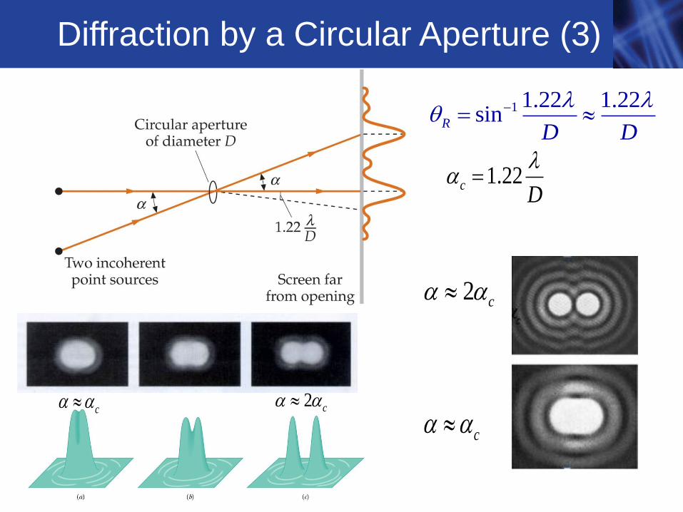
Optical Resolution
• For a circular opening of
diameter D, the angle
between the central
bright maximum and the
first minimum is
• The circular geometry
leads to the additional
numerical factor of 1.22
Section 25.8
1.22
D

Telescope Example
Section 25.8
• If the two sources are sufficiently far apart, they can
be seen as two separate diffraction spots (A)
• Two objects will be resolved when viewed through an
opening of diameter D if the light rays from the two
objects are separated by an angle at least as large
as θmin
min
1.22'Rayleigh s Criterion
D
Diffraction by a Circular Aperture (1)
telescope example

Diffraction by a Circular Aperture (2)
• The diffraction pattern consists of a bright circular
region and concentric rings of bright anddark fringes.
• The first minimum for the
diffraction pattern of a circular
aperture of diameter D is located by sin 1.22D
geometric factor
1 1.22 1.22sinR
D D
sinsin
2 2
ax
a
For a single slit
diffraction, the first
dark fringe occurs at
Rayleigh’s criterion
Diffraction by a Circular Aperture (3)
2 c
1.22cD
1 1.22 1.22sinR
D D
c 2 c
c

Example: Hubble Space Telescope (1)

Example: Hubble Space Telescope (2) • The diameter of the Hubble Space
Telescope is 2.4 m
Question: What is the minimum angular
resolution of the Hubble Space
Telescope?
Answer:
Using Rayleigh’s Criterion with green light of wavelength 550 nm we get
which corresponds to the angle subtended by a dime located 64 km away
91 71.22 550 10 m
sin 1.22 2.8 102.4 m
Rd

Demo - Diffraction Gratings
• Because diffraction gratings produce widely spaced narrow maxima, they can be used to determine the wavelength of monochromatic light by rearranging
• Monochromatic light incident on a diffraction grating will produce lines on a screen at widely separated angles
sin 0, 1, 2,...d
mm
sin , ( 0, 1, )d m m
Demo
1sin 0, 1, 2,...m
md
Supplemental Slides

Single Slit Diffraction: First Dark Fringe (1)
• We start with light emitted from the top edge of the slit and from the center of the slit as shown
• To analyze the path difference we show an expanded version of our figure to the right
• Here we assume that the point P on the screen is far enough away that the rays r1 and r2 are parallel and make an angle with the central axis
C

Single Slit Diffraction: First Dark Fringe (2)
• We assume that the point P on the screen is far
enough away that the rays r1 and r2 are parallel and
make an angle with thecentral axis
• Therefore the path length difference
for these two rays is
• The criterion for the first dark fringe is
• Although we chose one ray originating from the top edge of the
slit and one from the middle of the slit to locate the first dark
fringe, we could have used any two rays that originated a/2
apart inside the slit
sinsin or
/ 2 2
x ax
a
sinsin
2 2
ax or a
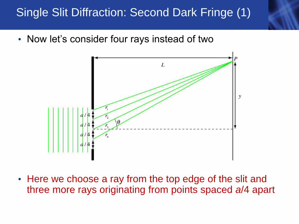
Single Slit Diffraction: Second Dark Fringe (1)
• Now let’s consider four rays instead of two
• Here we choose a ray from the top edge of the slit and three more rays originating from points spaced a/4 apart

Single Slit Diffraction: Second Dark Fringe (2)
• The path length difference between the pairs of
rays (r1,r2), (r2,r3), (r3,r4) is given by
• The dark fringe is given by
sinsin or
/ 4 4
x ax
a
sin or sin 2
4 2
ax a
This equation describes the second dark fringe
At this point we could take six pairs and eight pairs and describe the third and fourth dark fringes, etc.
The final result is
sin or sin 2
4 2
aa
sin 1,2,3,...a m m

Single Slit Intensity
• If the screen is placed a sufficiently large distance from the slits, the angle will be small and we can make the approximation
• We can express the position of the dark fringes as
• The intensity of light passing through a single slit can be calculated but we will not present the derivation here
• The intensity I relative to Imax that we would get if there were no slit is
• We can see that this expression for the intensity will be zero for sin() = 0, which means = m for m = 1, 2, 3, … consistent with
sin or 1,2,3,...ay m L
a m m y mL a
2
max
sin where sin
aI I
sin tan /y L
sin 1,2,3,...a m m

Single Slit Intensity: Dark Fringes
• We can write
which gives the same result for the diffraction minima as our
Huygens’ construction
• If the screen is placed a sufficiently large distance from the slits,
we can make the small angle approximation
and write
sin sin or sin ( 1,2,3,...)a a
m a m m
ay
L
2
max
sinI I
,L
y ma
or 1,2,3,...
ay m Lm y m
L a

Example - Single Slit Intensity Distribution
• If we take L = 2.0 m, a = 5.010-6 m = 5.0x 10³ nm, and = 550
nm, we get the following intensity distribution
• Note that a >
1,2,3,...m L
y ma
2
max
sin sin
aI I
ay
L
,L
y ma
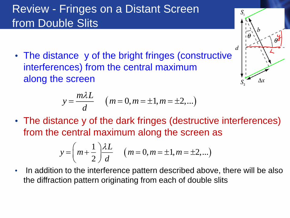
Review - Fringes on a Distant Screen from Double Slits
• The distance y of the bright fringes (constructive
interferences) from the central maximum
along the screen
• The distance y of the dark fringes (destructive interferences)
from the central maximum along the screen as
• In addition to the interference pattern described above, there will be also
the diffraction pattern originating from each of double slits
0, 1, 2,...m L
y m m md
1
0, 1, 2,...2
Ly m m m m
d

Double Slits - Interference + Diffraction (1)
Double Slit (slit width a<< Single Slit (slit width a~
Double Slit (slit width a~
Interference Difraction
0, 1, 2,...m L
y m m md
1
0, 1, 2,...2
Ly m m m m
d
2
max4 cosdy
I IL
d is the distance between two slits

Pattern for single slit diffraction, a ~ or a >
Pattern for double slit interference, a <<
Double Slits - Interference + Diffraction (2)
Intensity pattern for a double slit including interference and diffraction assuming L = 2.0 m, a = 5.010-6m = 5.0x10³ nm, d = 1.010-5 m, and = 550 nm d is two slits spacing

Double Slits - Interference + Diffraction (3) (a ~
• With diffraction effects the intensity of the interference pattern
from double slits is given by
• If the screen is placed a sufficiently large distance from the slits
then we can write
2
2
max
sincos sin sin
a dI I
and ay dy
L L
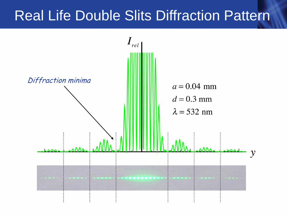
Real Life Double Slits Diffraction Pattern
Diffraction minima


