Embed Size (px)
Citation preview
Giancoli Physics: Principles with Applications, 6th Edition
© 2005 Pearson Education, Inc., Upper Saddle River, NJ. All rights reserved. This material is protected under all copyright laws as they currently exist. No portion of this material may be reproduced, in any form or by any means, without permission in writing from the publisher.
200
CHAPTER 24: The Wave Nature of Light Answers to Questions 1. Huygens’ principle applies both to sound waves and water waves. Huygens’ principle applies to all
waves that form a wave crest. Both sounds and water waves can be represented in this way. 2. A piece of evidence that light is energy is that you can focus the light from the Sun with a magnifying
glass on to a sheet of paper and burn a hole in it. You have added so much energy to the paper that its temperature rises to the point where it ignites.
3. There are certain situations where describing light as rays works well (for example, lenses) and there are
other situations where describing light as waves works well (for example, diffraction). Actually, the ray model doesn’t work at all when describing diffraction. Thus, there are always limitations to the “models” we use to describe nature and we need to realize what these are.
4. The main reason that we can hear sounds around corners, but not see around corners, is diffraction.
Sound waves have very long wavelengths when compared to light waves, which makes diffraction effects much more obvious. Diffraction effects are very noticeable once the size of the object that the wave is diffracting around is about the same size as the wavelength of the wave. The wavelength of sound is on the order of 1 m, while the wavelength of light is on the order of 0.1 µm. A secondary reason is reflection. Sounds waves reflect off of walls very well in a specular manner, and so can bounce around corners, but light reflects off of the walls in a very diffuse manner.
5. The wavelength of light in a medium such as water is decreased when compared to the wavelength in air.
Thus, sind mθ λ= says that θ is decreased for a particular m and d. This means that the bright spots on the screen are more closely packed together in water than in air.
6. As red light is switched to blue light, the wavelength of the light is decreased. Thus, sind mθ λ= says
that θ is decreased for a particular m and d. This means that the bright spots on the screen are more closely packed together with blue light than with red light.
7. Destructive interference occurs when the path lengths of two rays of light from the same source differ by
odd half-integers of the wavelength ( ( )122 , 3 2 , 5 2 , mλ λ λ λ+ , etc.). Under these conditions, the
wave crests from one ray match up with the wave troughs from the other ray and cancellation occurs (destructive interference).
8. One reason was that the double-slit experiment allowed scientists to measure an actual wavelength,
which was something that could not be done at the time with diffraction observations. Another reason was that using a particle model, you could explain diffraction in a qualitative way by talking about the particles bouncing off the edges of the diffracting object or the two edges of a single slit. When a second slit is added, the particle model had a much more difficult time explaining why there are now dark spots where the particles used to be able to strike with only one slit open.
9. Similarities between doing a double-slit experiment with sound and light: the sources must be coherent
for the interference pattern to be observed; they both produce a pattern of high and low intensity at some distance away from the double slit (bright and dark for the light and loud and quiet for the sound); they both work best with a single-frequency source. Differences between doing a double-slit experiment with

Giancoli Physics: Principles with Applications, 6th Edition
© 2005 Pearson Education, Inc., Upper Saddle River, NJ. All rights reserved. This material is protected under all copyright laws as they currently exist. No portion of this material may be reproduced, in any form or by any means, without permission in writing from the publisher.
201
sound and light: The slits for light must be extremely close together when compared to sound; you don’t actually need slits for sound (just use two speakers).
10. The reason you do not get an interference pattern from the two headlights of a distant car is that they are
not coherent light sources (they have random phases). Thus, you cannot produce zones of destructive and constructive interference where the crests and troughs match up or the crests and crests match up. Also, the headlights are far enough apart that even if they were coherent, the interference pattern would be so tightly packed that it would not be observable with the unaided eye.
11. Basically there would be two overlapping single-slit diffraction patterns, with one being blue and the
other being red. Wherever the two different patterns overlapped, there would be a purplish (red + blue) bright spot. There would not be a central bright spot, due to the different wavelengths of the two colors.
12. The two faces of the pane of glass are parallel to each other, so the white light rays that were separated
into colors as they entered the front face all come out of the second face at the same angle as each other. When these rays reach your eyes, they all combine back together into white light. The separated colors in the prism reach the other face of the prism at all different angles (since the second face of the prism is not parallel to the first face), which means that all of these different colors leave the prism at all different angles. These light rays are still separated into colors when they reach your eyes, which allows you to see a rainbow of colors at different angles.
13. Since red light is bent less than violet light in glass (the index of refraction for red light in glass is less
than the index of refraction for violet light in glass), the focal length of both a converging lens and a diverging lens is longer for red light and shorter for violet light.
14. By looking at the direction and the relative amount that the light rays bend at each interface, we can infer
the relative sizes of the indices of refraction in the different materials (bends toward normal = faster material to slower material or smaller n material to larger n material; bends away from normal = slower material to faster material or larger n material to smaller n material). From the first material to the second material the ray bends toward the normal, thus it slows down and n1 < n2. From the second material to the third material the ray bends away from the normal, thus it speeds up and n2 > n3. Careful inspection shows that the ray in the third material does not bend back away from the normal as far as the ray was in the first material, thus the speed in the first material is the faster than in the third material and n1 < n3. Thus, the overall ranking of indices of refraction is: n1 < n3 < n2.
15. As you squeeze your fingers together, you start to see vertical bright and dark bands that are aligned
parallel to your fingers. The dark bands get wider as you continue to bring your fingers closer together, until at one point, when your fingers are still not actually touching, the dark bands seem to quickly jump in and darken the entire gap.
16. (a) When you immerse a single-slit diffraction apparatus in water, the wavelength of light gets
smaller, due to the increase in the index of refraction, and the diffraction pattern gets more closely
spaced. The equation sinDλ
θ = for the half-width of the central maximum says that θ is
decreased for a particular D when the wavelength decreases. And the equation for the locations of
the minima, sinmDλ
θ = , also indicates that θ is decreased for a particular m and D when the
wavelength decreases. This means that the bright spots on the screen are more closely spaced in water than in air.
Chapter 24 The Wave Nature of Light
© 2005 Pearson Education, Inc., Upper Saddle River, NJ. All rights reserved. This material is protected under all copyright laws as they currently exist. No portion of this material may be reproduced, in any form or by any means, without permission in writing from the publisher.
202
(b) When you perform a single-slit diffraction experiment in vacuum, the wavelength of light gets slightly larger, due to the decrease in the index of refraction, and the diffraction pattern spreads
farther apart. The equation sinDλ
θ = for the half-width of the central maximum says that θ is
increased for a particular D when the wavelength increases. And the equation for the locations of
the minima, sinmDλ
θ = , also indicates that θ is increased for a particular m and D when the
wavelength increases. This means that the bright spots on the screen are spread farther apart in vacuum than in air.
17. (a) When you increase the slit width in a single-slit diffraction experiment, the spacing of the
fringes decreases. The equation for the location of the minima, sinmDλ
θ = , indicates that θ is
decreased for a particular m and λ when the width D increases. This means that the bright spots on the screen are more closely packed together for a wider slit.
(b) When you increase the wavelength of light used in a single-slit diffraction experiment, the
spacing of the fringes increases. The equation for the location of the minima, sinmDλ
θ = , indicates
that θ is increased for a particular m and D when the wavelength increases. This means that the bright spots on the screen are spread further apart for a longer wavelength.
18. The interference pattern created by the diffraction grating with 104 lines/cm has bright maxima that are
more sharply defined and narrower than the interference pattern created by the two slits 10-4 cm apart. 19. (a) The advantage of having many slits in a diffraction grating is that this makes the bright maxima
in the interference pattern more sharply defined, brighter, and narrower. (b) The advantage of having closely spaced slits in a diffraction grating is that this spreads out the
bright maxima in the interference pattern and makes them easier to measure. 20. (a) The color at the top of the rainbow for the diffraction grating is violet. The equation
sind mθ λ= says that θ is smallest (thus, the deviation from horizontal is smallest) for the shortest wavelength, for a given d and m. The wavelength of violet light (450 nm) is shorter than that of red light (700 nm).
(b) The color at the top of a rainbow for the prism is red. The index of refraction for transparent materials (like the glass that makes up the prism) is smaller for long (red) wavelengths and larger for short (violet) wavelengths. Since the red light encounters a smaller index of refraction as it goes through the prism, it doesn’t slow as much as the violet light, which also means that it doesn’t bend as much as the violet. If the red light is bent away from the horizontal direction least, it will appear at the top of the rainbow.
21. For the red and violet colors from different orders to overlap, the angles in the equation
sind mθ λ= would need to be equal. Mathematically, this means: ( )( ) ( )m 1 400 nm m 700 nm
d d+
< .
In other words, the mth order 700 nm line overlaps the (m+1)th order 400 nm line. Reducing this equation, we get m > 4/3. So, starting with the 2nd order 700 nm line and the 3rd order 400 nm line, the observed spectra will always overlap at this and higher orders. This answer does not depend on d. As you can see from the above equation, the slit spacing cancels out.

Giancoli Physics: Principles with Applications, 6th Edition
© 2005 Pearson Education, Inc., Upper Saddle River, NJ. All rights reserved. This material is protected under all copyright laws as they currently exist. No portion of this material may be reproduced, in any form or by any means, without permission in writing from the publisher.
203
22. Once the thickness of the film becomes more than a few wavelengths thick, several interference patterns become mixed together, and it is hard to see any individual effects. When the thickness of the film is only about 1 λ thick, then the reflections from the top and bottom surfaces of the film for each color have path differences of just one constructive interference (path difference = λ/2) and one destructive interference (path difference = λ) patterns. It is easy for our eyes to pick out these widely spaced bright colors that are separated by dark areas on the film. Once the film gets very thick, though, there are many constructive (λ/2, 3λ/2, 5λ/2, etc.) and many destructive (λ, 2λ, 3λ, etc.) path differences allowed. The resulting interference patterns are all closely spaced and overlapping, making it difficult for our eyes to distinguish between the bright and dark areas. As the film gets even thicker, the larger amount of overlap causes all the colors to run together, making it impossible to see the individual interference patterns.
23. There are many, many circular tracks on a CD and each track is made up of a series of pits and high
spots. Light reflects very well off of the high spots and not the low spots. Thus, when you shine white light on a CD, each track is a slightly different distance from you, and as the light reflects off of each track to you, they each have a different path length. Thus, you’ll basically see a colorful diffraction grating pattern. If a monochromatic light is used, you will see a single-color interference pattern. In other words, instead of seeing the full rainbow of colors spreading out from the center of the CD (as shown in Figure 24-56), there would just be several “spokes” of the same color as your source spreading out from the center of the CD. The spacings of these “spokes” can be used just like a diffraction grating to determine that the track spacing on the CD is approximately 1600 nm.
24. As you move farther away from the center of the curved piece of glass on top, the path differences
change more rapidly due to the curvature. Thus, you get higher order interference patterns more closely spaced together. An air wedge has equally spaced interference patterns because as you move farther from the contact point of the flat piece of glass on top, the path differences change linearly.
25. If yellow/green light is getting reflected back to us, then the coating must be designed to transmit violet,
blue, orange, and red light completely. 26. At the edge of the oil drop, the film is so thin that the path difference between the light reflecting off of
the top surface and the light going through the oil and reflecting off of the bottom surface is so small that we can consider it to be zero. Thus, the two different rays of light must be in phase when they reach our eyes. We know that the phase of the light being reflected off of the top surface of the oil must have been flipped 180°, since the index of refraction of oil is greater than that of air. Thus, the reflection off of the bottom surface of the film (where it touches the water), must also have flipped the phase of the light 180°. This tells us that the index of refraction of the water is higher than that of the oil. Thus, we know that the index of refraction of the oil is greater than that of air and less than that of water: 1.00 < n < 1.33.
27. Polarization tells us that light is a transverse wave. Longitudinal waves cannot be polarized. 28. Polarized sunglasses completely (100%) block horizontally polarized glare and block all other
polarizations of light 50%. Regular sunglasses just block 50-75% of all light coming in. The advantage of polarized sunglasses is the total elimination of glare. Even if regular sunglasses block a glare at 75%, the glare is so intense that it still makes it difficult for our eyes.
29. To determine if a pair of sunglasses is polarizing or not, first find the glare (strong reflection) from a
light source on a horizontal non-metallic surface (water, tiled floor, polished tabletop, top of car). Then look at the reflection through the sunglasses and rotate them. If they are polarizing sunglasses, then there

Chapter 24 The Wave Nature of Light
© 2005 Pearson Education, Inc., Upper Saddle River, NJ. All rights reserved. This material is protected under all copyright laws as they currently exist. No portion of this material may be reproduced, in any form or by any means, without permission in writing from the publisher.
204
should be orientations of the glasses that almost completely block out the glare and other orientations that let 50% of the glare through. If they are not polarizing sunglasses, the glare will be slightly diminished by the same amount at all orientations of the glasses, but it will never completely go away.
30. The first sheet of polarizer will diminish the intensity of the incoming non-polarized light by 50%:
11 02I I= . The next polarizer will diminish the light again, but this time only by a factor of 2cos θ :
2 o 3 31 1 1 04 8cos 30I I I I= = = . The next polarizer will diminish the light by the same factor:
2 o 3 93 2 2 04 32cos 30I I I I= = = . The last polarizer will again diminish the light by the same factor:
2 o 3 274 3 3 0 04 128cos 30 0.211I I I I I= = = = . Thus, about 21% of the light gets through these four polarizers
when each one is rotated by 30°. 31. If Earth had no atmosphere, the “color” of the sky would be black (and dotted with stars and planets) at
all times. This is the condition of the sky that the astronauts found on the Moon, which has no atmosphere. The reason the sky is blue for Earth, is that the air molecules scatter light from the Sun in all directions, and preferentially scatter blue light down to the surface. If there were no air molecules to scatter the light from the Sun, the only light we would see would be from the stars/planets and directly from the Sun and the rest would be black.
32. If the atmosphere were 50% more dense, sunlight would be much redder than it is now. As the
atmosphere increased in density, more and more of the blue light would be scattered away in all directions, making the light that reaches the ground very red. Think of the color of a deep red sunset, but this would be the color even at noon.
Solutions to Problems 1. For constructive interference, the path difference is a multiple of the wavelength: sin , 0, 1, 2, 3, ...d m mθ λ= = . For the fifth order, we have ( ) ( )51.6 10 m sin8.8 5 ,λ−× ° = which gives 74.9 10 m.λ −= ×
2. For constructive interference, the path difference is a multiple of the wavelength: sin , 0, 1, 2, 3,...d m mθ λ= = . For the third order, we have ( )( )9sin18 3 610 10 m ,d −° = × which gives 65.9 10 m 5.9 m.d µ−= × =
3. For constructive interference, the path difference is a multiple of the wavelength: sin , 0, 1, 2, 3, ...d m mθ λ= = . We find the location on the screen from tan .y L θ= For small angles, we have sin tan ,θ θ≈ which gives
.m mLy Ld dλ λ⎛ ⎞= =⎜ ⎟
⎝ ⎠

Giancoli Physics: Principles with Applications, 6th Edition
© 2005 Pearson Education, Inc., Upper Saddle River, NJ. All rights reserved. This material is protected under all copyright laws as they currently exist. No portion of this material may be reproduced, in any form or by any means, without permission in writing from the publisher.
205
For adjacent fringes, 1,m∆ = so we have
;L mydλ ∆
∆ =
( ) ( )( )3
5.00m 10.065m ,
0.048 10 mλ−
=×
which gives 76.2 10 m.λ −= ×
The frequency is
( )( )
8
7
3.00 10 m s
6.24 10 mcfλ −
×= = =
×144.8 10 Hz.×
4. For constructive interference, the path difference is a multiple of the wavelength: sin , 0, 1, 2, 3, ...d m mθ λ= = . We find the location on the screen from tan .y L θ= For small angles, we have sin tan ,θ θ≈ which gives
.m mLy Ld dλ λ⎛ ⎞= =⎜ ⎟
⎝ ⎠
For adjacent fringes, 1,m∆ = so we have
;L mydλ ∆
∆ =
( )( )( )
( )9
23
3.6m 656 10 m 13.9 10 m
0.060 10 m
−−
−
×= = × =
×3.9 cm.
5. For constructive interference, the path difference is a multiple of the wavelength: sin , 0, 1, 2, 3, ...d m mθ λ= = . We find the location on the screen from tan .y L θ= For small angles, we have sin tan ,θ θ≈ which gives
.m mLy Ld dλ λ⎛ ⎞= =⎜ ⎟
⎝ ⎠
For the fourth order we have
( )( )( )9
31.5m 680 10 m 4
48 10 m ,d
−−
×× = which gives 58.5 10 md −= × = 0.085 mm.
6. For constructive interference, the path difference is a multiple of the wavelength: sin , 0, 1, 2, 3, ...d m mθ λ= = . We find the location on the screen from tan .y L θ= For small angles, we have sin tan ,θ θ≈ which gives

Chapter 24 The Wave Nature of Light
© 2005 Pearson Education, Inc., Upper Saddle River, NJ. All rights reserved. This material is protected under all copyright laws as they currently exist. No portion of this material may be reproduced, in any form or by any means, without permission in writing from the publisher.
206
.m mLy Ld dλ λ⎛ ⎞= =⎜ ⎟
⎝ ⎠
For the second order of the two wavelengths, we have
( )( )( )
( )9
33
1.6m 480 10 m 22.84 10 m 2.84mm;
0.54 10 ma
aL my
dλ
−−
−
×= = = × =
×
( )( )( )
( )9
33
1.6m 620 10 m 23.67 10 m 3.67 mm.
0.54 10 mb
bL my
dλ
−−
−
×= = = × =
×
Thus the two fringes are separated by 3.67 mm 2.84mm− = 0.8 mm. 7. For constructive interference of the second order for the blue light, we have ( )( )sin 2 460nm 920nm.bd mθ λ= = = For destructive interference of the other light, we have ( )1
2sin , 0, 1, 2, 3, ...d m mθ λ= ′ + ′ = . When the two angles are equal, we get ( )1
2920nm , 0, 1, 2, 3, ...m mλ= ′ + ′ = . For the first three values of ,m′ we get ( )1
2920nm 0 ,λ= + which gives 31.84 10 nm;λ = ×
( )12920nm 1 ,λ= + which gives 613nm;λ =
( )12920nm 2 ,λ= + which gives 368nm.λ =
The only one of these that is visible light is 613 nm. 8. For destructive interference, the path difference is ( )1
2sin , 0, 1, 2, 3, ... ;d m mθ λ= + = or
( )( )
( ) ( )( )12 1
2
2.5cmsin 0.50 , 0, 1, 2, 3, ...
5.0cmm
m mθ+
= = + = .
The angles for the first three regions of complete destructive interference are
( ) ( )( )
12 1
0 02sin 0 0.50 0.25, 15 ;m
dλ
θ θ+
= = + = = °
( ) ( )( )
12 1
1 12sin 1 0.50 0.75, 49 ;m
dλ
θ θ+
= = + = = °
( ) ( )( )
12 1
2 2sin 2 0.50 1.25,m
dλ
θ+
= = + = therefore, no third region.
We find the locations at the end of the tank from tan ;y L θ= ( )0 2.0m tan15 0.52m;y = ° = ( )1 2.0m tan 49 2.3m.y = ° = Thus you could stand
0.52 m, or 2.3 m away from the line perpendicular to the board midway between the openings.

Giancoli Physics: Principles with Applications, 6th Edition
© 2005 Pearson Education, Inc., Upper Saddle River, NJ. All rights reserved. This material is protected under all copyright laws as they currently exist. No portion of this material may be reproduced, in any form or by any means, without permission in writing from the publisher.
207
9. The 180° phase shift produced by the glass is equivalent to a path length of 12 .λ For constructive
interference on the screen, the total path difference is a multiple of the wavelength: 1
max2 sin , 0, 1, 2, 3, ... ;d m mλ θ λ+ = = ± ± ± or ( )12sin , 0, 1, 2, 3, ...d m mθ λ= − = ± ± ± .
For destructive interference on the screen, the total path difference is ( )1 1
max2 2sin , 0, 1, 2, 3, ... ;d m mλ θ λ+ = + = ± ± ± or sin , 0, 1, 2, 3, ...d m mθ λ= = ± ± ± . Thus the pattern is just the reverse of the usual double-slit pattern. 10. For constructive interference, the path difference is a multiple of the wavelength: sin , 0, 1, 2, 3, ...d m mθ λ= = . We find the location on the screen from tan .y L θ= For small angles, we have sin tan ,θ θ≈ which gives
.m mLy Ld dλ λ⎛ ⎞= =⎜ ⎟
⎝ ⎠
For the third order we have
( )( )( )9
33 1.6m 500 10 m
12 10 m ,d
−−
×× = which gives 42.0 10 m.d −= ×
With the new wavelength, then, the second-order maximum is located a distance of
mLydλ
=
( )( )( )9
4
2 1.6m 650 10 m0.010m
2.0 10 m
−
−
×= =
×
10mm= from the central maximum. 11. For constructive interference, the path difference is a multiple of the wavelength: sin , 0, 1, 2, 3, ...d m mθ λ= = . We find the location on the screen from tan .y L θ= For small angles, we have sin tan ,θ θ≈ which gives
.m mLy Ld dλ λ⎛ ⎞= =⎜ ⎟
⎝ ⎠
For adjacent fringes, 1,m∆ = so we have
L mydλ ∆
∆ =
( )( )( )9
33
5.0m 544 10 m 12.7 10 m 2.7 mm.
1.0 10 m
−−
−
×= = × =
×
12. The presence of the water changes the wavelength: waterwater
480nm 361nm.1.33n
λλ = = =
For constructive interference, the path difference is a multiple of the wavelength in the water: watersin , 0,1,2,3,... .d m mθ λ= =

Chapter 24 The Wave Nature of Light
© 2005 Pearson Education, Inc., Upper Saddle River, NJ. All rights reserved. This material is protected under all copyright laws as they currently exist. No portion of this material may be reproduced, in any form or by any means, without permission in writing from the publisher.
208
We find the location on the screen from tan .y L θ= For small angles, we have sin tan ,θ θ≈ which gives
water water .m mLy Ld dλ λ⎛ ⎞= =⎜ ⎟
⎝ ⎠
For adjacent fringes, 1,m∆ = so we have
waterL myd
λ ∆∆ =
( )( )( )
( )9
35
0.400m 361 10 m 12.41 10 m 2.41mm.
6.00 10 m
−−
−
×= = × =
×
13. To change the center point from constructive interference to destructive interference, the phase shift
produced by the introduction of the plastic must be an odd multiple of half a wavelength, corresponding to the change in the number of wavelengths in the distance equal to the thickness of the plastic. The minimum thickness will be for a shift of a half wavelength:
( )plastic 1plastic 2
plastic
1 ;tnt t t tN n
λ λ λ λ λ⎛ ⎞ ⎛ ⎞⎛ ⎞ ⎛ ⎞ ⎛ ⎞= − = − = − =⎜ ⎟ ⎜ ⎟⎜ ⎟ ⎜ ⎟ ⎜ ⎟⎜ ⎟ ⎝ ⎠ ⎝ ⎠ ⎝ ⎠⎝ ⎠⎝ ⎠
( ) ( ) 1
21.60 1 ,640nm
t⎡ ⎤− =⎢ ⎥
⎢ ⎥⎣ ⎦ which gives 533nm.t =
14. We find the speed of light from the index of refraction, .cvn
= For the change, we have
( ) red violetred violet
violet
violet
c cn nv v
v cn
⎡ ⎤⎛ ⎞ ⎛ ⎞−⎢ ⎥⎜ ⎟ ⎜ ⎟
− ⎝ ⎠ ⎝ ⎠⎣ ⎦=⎛ ⎞⎜ ⎟⎝ ⎠
( ) ( )( )
violet red
red
1.665 1.6170.030 3.0%.
1.617n n
n− −
= = = =
15. We find the angles of refraction in the glass from 1 1 2 2sin sin ;n nθ θ= ( ) ( ) 2,4501.00 sin 60.00 1.4820 sin ,θ° = which gives 2,450 35.76 ;θ = ° ( ) ( ) 2,7001.00 sin 60.00 1.4742 sin ,θ° = which gives 2,700 35.98 .θ = ° Thus the angle between the refracted beams is 2,700 2,450 35.98 35.76 0.22 .θ θ− = ° − ° = °

Giancoli Physics: Principles with Applications, 6th Edition
© 2005 Pearson Education, Inc., Upper Saddle River, NJ. All rights reserved. This material is protected under all copyright laws as they currently exist. No portion of this material may be reproduced, in any form or by any means, without permission in writing from the publisher.
209
16. For the refraction at the first surface, we have air sin sin ;a bn nθ θ= ( ) ( ) 11.00 sin 45 1.642 sin ,bθ° = which gives 1 25.51 ;bθ = ° ( ) ( ) 21.00 sin 45 1.619 sin ,bθ° = which gives 2 25.90 .bθ = ° We find the angle of incidence at the second surface from ( ) ( )90 90 180 ,b c Aθ θ° − + ° − + = ° which gives 1 1 60.00 25.51 34.49 ;c bAθ θ= − = ° − ° = ° 2 2 60.00 25.90 34.10 .c bAθ θ= − = ° − ° = ° For the refraction at the second surface, we have airsin sin ;c dn nθ θ= ( ) ( ) 11.642 sin 34.49 1.00 sin ,dθ° = which gives 1 68.4 from the normal;dθ = °
( ) ( ) 21.619 sin34.10 1.00 sin ,dθ° = which gives 2 65.2 from the normal.dθ = °
17. We find the angle to the first minimum from
( )( )( )
9
1min 1min3
1 580 10 msin 0.0132, so 0.755 .
0.0440 10 mmDλθ θ
−
−
×= = = = °
×
Thus the angular width of the central diffraction peak is ( )1 1min2 2 0.755 1.51 .θ θ∆ = = ° = ° 18. The angle from the central maximum to the first minimum is 17.5 .° We find the wavelength from 1minsin ;D mθ λ= ( ) ( ) ( )62.60 10 m sin 17.5 1 ,λ−× ° = which gives 77.82 10 m 782nm.λ −= × =
19. For constructive interference from the single slit, the path difference is ( )1
2sin , 1, 2, 3, ...D m mθ λ= + = . For the first fringe away from the central maximum, we have ( ) ( )( )6 93
1 23.20 10 m sin 520 10 m ,θ− −× = × which gives 1 14.1 .θ = °
We find the distance on the screen from ( )1 1tan 10.0m tan14.1 2.51m.y L θ= = ° = 20. We find the angle to the first minimum from
( )( )9
1min 3
1 450 10 msin 0.00045.
1.0 10 mmDλθ
−
−
×= = =
×
We find the distance on the screen from tan .y L θ= For small angles, we have sin tan ,θ θ≈ which gives ( )( )sin 5.0m 0.00045 0.00225m.y L θ= = =

Chapter 24 The Wave Nature of Light
© 2005 Pearson Education, Inc., Upper Saddle River, NJ. All rights reserved. This material is protected under all copyright laws as they currently exist. No portion of this material may be reproduced, in any form or by any means, without permission in writing from the publisher.
210
Thus the width of the central maximum is 2 0.0045m 0.45cm.y = = 21. The angle from the central maximum to the first bright fringe is 16 .° For constructive interference from the single slit, the path difference is ( )1
2sin , 1, 2, 3, ...D m mθ λ= + = . For the first fringe away from the central maximum, we have ( ) ( )( )93
2sin 16 653 10 m ,D −° = × which gives 63.6 10 m 3.6 m.D µ−= × =
22. We find the angle to the first minimum from
( )( )( )
9
1min 1min3
1 589 10 msin 0.0169, so 0.970 .
0.0348 10 mmDλθ θ
−
−
×= = = = °
×
We find the distance on the screen from ( ) 2
1 1tan 2.30m tan 0.970 3.89 10 m 3.89cm.y L θ −= = ° = × = Thus the width of the peak is ( )1 12 2 3.89cm 7.79cm.y y∆ = = = 23. We find the angular half-width θ of the central maximum from
sin ;Dλθ =
955.0 440 10 msin ,
2 D
−° ×⎛ ⎞ =⎜ ⎟⎝ ⎠
which gives 79.53 10 m.D −= ×
24. We find the angle to the first minimum from the distances:
( )( )
11min 1min2
9.20cmtan 0.0180 sin ,
255cmθ θ= = = because the angle is small.
We find the slit width from 1minsin ;D mθ λ= ( ) ( )( )90.0180 1 415 10 m ,D −= × which gives 52.30 10 m 0.0230mm.D −= × =
25. Because the angles are small, we have
( )111min 1min2tan sin .
yL
θ θ∆
= =
The condition for the first minimum is
111min 2sin .yD D
Lθ λ∆
= =
If we form the ratio of the expressions for the two wavelengths, we get
1
1
;b b
a a
yy
λλ
∆=
∆
( )
( )( )
1 420nm,
4.0cm 650nmby∆
= which gives 1 2.6cm.by∆ =

Giancoli Physics: Principles with Applications, 6th Edition
© 2005 Pearson Education, Inc., Upper Saddle River, NJ. All rights reserved. This material is protected under all copyright laws as they currently exist. No portion of this material may be reproduced, in any form or by any means, without permission in writing from the publisher.
211
26. There will be no diffraction minima if the angle for the first minimum is greater than 90 .° Thus the limiting condition is 1minsin ;D mθ λ= ( )max maxsin 90 1 , or .D Dλ λ° = =
27. We find the angle for the second order from sin ;d mθ λ= ( ) ( )( )5 91.45 10 m sin 2 560 10 m ,θ− −× = × which gives sin 0.0772,θ = so 4.43 .θ = °
28. We find the wavelength from sin ;d mθ λ=
( ) ( )21 10 m cm sin 28.0 3 ,3500lines cm
λ−⎡ ⎤° =⎢ ⎥
⎢ ⎥⎣ ⎦ which gives 74.47 10 m 447 nm.λ −= × =
29. We find the slit separation from sin ;d mθ λ= ( )( )9sin18.0 3 630 10 m ,d −° = × which gives 6 46.12 10 m 6.12 10 cm.d − −= × = ×
The number of lines/cm is
( )
34
1 1 1.64 10 lines cm.6.12 10 cmd −
= = ××
30. Because the angle increases with wavelength, to have a complete order we use the largest wavelength. The maximum angle is 90°, so we have sin ;d mθ λ=
( ) ( ) ( )2 91 10 m cm sin 90 700 10 m ,8300lines cm
m− −⎡ ⎤° = ×⎢ ⎥
⎢ ⎥⎣ ⎦ which gives 1.70.m =
Thus only one full order can be seen on each side of the central white line. 31. We find the slit separation from sin ;d mθ λ= ( )( )9sin15.5 1 589 10 m ,d −° = × which gives 62.20 10 m 2.20 m.d µ−= × = We find the angle for the fourth order from sin ;d mθ λ= ( ) ( )( )6 9
42.20 10 m sin 4 589 10 m ,θ− −× = × which gives 4sin 1.069,θ = so there is no fourth order.
32. We find the angles for the second order from sind mθ λ= with 2.m =
( )715
1 sin 2 7.0 10 m6.0 10 lines m
θ −= ××
gives 1sin 0.84,θ = so 1 57.1 .θ = °
( )725
1 sin 2 4.5 10 m6.0 10 lines m
θ −= ××
gives 2sin 0.54,θ = so 2 32.7 .θ = °
Therefore, 57.1 32.7 24 .θ∆ = ° − ° = °

Chapter 24 The Wave Nature of Light
© 2005 Pearson Education, Inc., Upper Saddle River, NJ. All rights reserved. This material is protected under all copyright laws as they currently exist. No portion of this material may be reproduced, in any form or by any means, without permission in writing from the publisher.
212
33. We find the wavelengths from sin ;d mθ λ=
( ) ( ) ( )2
11 10 m cm sin31.2 1 ,
9700lines cmλ−⎡ ⎤
° =⎢ ⎥⎢ ⎥⎣ ⎦
which gives 71 5.34 10 m 534nm;λ −= × =
( ) ( ) ( )2
21 10 m cm sin 36.4 1 ,
9700lines cmλ−⎡ ⎤
° =⎢ ⎥⎢ ⎥⎣ ⎦
which gives 72 6.12 10 m 612nm;λ −= × =
( ) ( ) ( )2
31 10 m cm sin 47.5 1 ,
9700lines cmλ−⎡ ⎤
° =⎢ ⎥⎢ ⎥⎣ ⎦
which gives 73 7.60 10 m 760nm.λ −= × =
34. The maximum angle is 90°, so we have sin ;d mθ λ=
( ) ( ) ( )2 91 10 m cm sin 90 633 10 m ,6000lines cm
m− −⎡ ⎤° = ×⎢ ⎥
⎢ ⎥⎣ ⎦ which gives 2.63.m =
Thus two orders can be seen on each side of the central white line. 35. Because the angle increases with wavelength, to have a full order we use the largest wavelength. The maximum angle is 90°, so we find the minimum separation from sin ;d mθ λ= ( )( )9
min sin 90 2 750 10 m ,d −° = × which gives 6 4min 1.50 10 m 1.50 10 cm.d − −= × = ×
The maximum number of lines/cm is
( )
34
min
1 1 6.67 10 lines cm.1.50 10 cmd −
= = ××
36. We find the angles for the first order from sin ;d mθ λ λ= =
( ) ( ) ( )2 9
4101 10 m cm sin 410 10 m ,
8500lines cmθ− −⎡ ⎤
= ×⎢ ⎥⎢ ⎥⎣ ⎦
which gives
410 410sin 0.3485, so 20.4 ;θ θ= = °
( ) ( ) ( )2 9
7501 10 m cm sin 750 10 m ,
8500lines cmθ− −⎡ ⎤
= ×⎢ ⎥⎢ ⎥⎣ ⎦
which gives
750 750sin 0.6375, so 39.6 .θ θ= = ° The distances from the central white line on the screen are ( )410 410tan 2.30m tan 20.4 0.855m;y L θ= = ° = ( )750 750tan 2.30m tan39.6 1.90m.y L θ= = ° = Thus the width of the spectrum is 750 410 1.90m 0.855m 1.05m.y y− = − = 37. We find the angle for the first order from sin ;d mθ λ λ= = 7sin 21.5 6.328 10 m,d −° = × which gives 61.73 10 m.d −= ×

Giancoli Physics: Principles with Applications, 6th Edition
© 2005 Pearson Education, Inc., Upper Saddle River, NJ. All rights reserved. This material is protected under all copyright laws as they currently exist. No portion of this material may be reproduced, in any form or by any means, without permission in writing from the publisher.
213
The number of lines per meter is
56
1 1 5.79 10 lines m.1.73 10 md −= = ×
×
38. Because the angles on each side of the central line are not the same, the incident light is not normal to the
grating. We use the average angles:
( )1
26 38 26 4826 43 26.72 ;
2θ
° ′ + ° ′= = ° ′ = °
( )2
41 08 41 1941 14 41.23 .
2θ
° ′ + ° ′= = ° ′ = °
We find the wavelengths from sin ;d mθ λ=
( ) ( ) ( )2
11 10 m cm sin 26.72 1 ,
9500lines cmλ−⎡ ⎤
° =⎢ ⎥⎢ ⎥⎣ ⎦
which gives 71 4.73 10 m 473nm;λ −= × =
( ) ( ) ( )2
21 10 m cm sin 41.23 1 ,
9500lines cmλ−⎡ ⎤
° =⎢ ⎥⎢ ⎥⎣ ⎦
which gives 72 6.94 10 m 694nm.λ −= × =
Note that the second wavelength is not visible. 39. We equate a path difference of one wavelength with a phase difference of 2 .π With respect to the incident wave, the wave that reflects at the top surface from the higher index of the soap bubble has a phase change of 1 .φ π= With respect to the incident wave, the wave that reflects from the air at the bottom surface of the bubble has a phase change due to the additional path-length but no phase change on reflection:
2film
2 2 0.tφ πλ
⎛ ⎞= +⎜ ⎟⎝ ⎠
For constructive interference, the net phase change is
( )1 1film2 2
film
2 2 2 , 0, 1, 2, ..., or , 0, 1, 2, ...t m m t m mφ π π π λλ
⎛ ⎞= − = = = + =⎜ ⎟⎝ ⎠
.
The wavelengths in air that produce strong reflection are given by
( )
( )( )( )
( )( )film 1
2
4 1.34 120nm 643nm2 .2 1 2 1
ntnm m m
λ λ= = = =+ + +
Thus we see that, for the light to be in the visible spectrum, the only value of m is 0:
( )( )643nm
643nm,0 1
λ = =+
which is an orange-red.
40. Between the 25 dark lines there are 24 intervals. When we add the half-interval at the wire end, we have
24.5 intervals, so the separation is
26.5cm 1.08cm.24.5intervals
=
Chapter 24 The Wave Nature of Light
© 2005 Pearson Education, Inc., Upper Saddle River, NJ. All rights reserved. This material is protected under all copyright laws as they currently exist. No portion of this material may be reproduced, in any form or by any means, without permission in writing from the publisher.
214
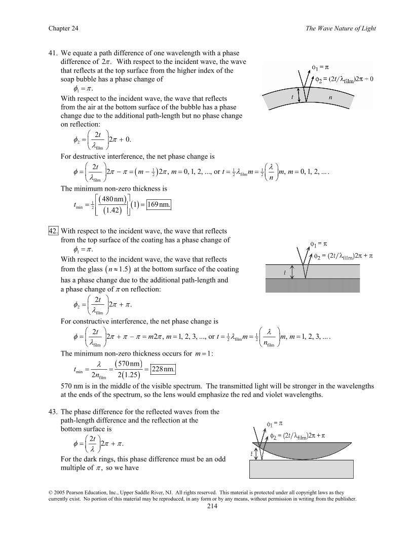
41. We equate a path difference of one wavelength with a phase difference of 2 .π With respect to the incident wave, the wave that reflects at the top surface from the higher index of the soap bubble has a phase change of 1 .φ π= With respect to the incident wave, the wave that reflects from the air at the bottom surface of the bubble has a phase change due to the additional path-length but no phase change on reflection:
2film
2 2 0.tφ πλ
⎛ ⎞= +⎜ ⎟⎝ ⎠
For destructive interference, the net phase change is
( )1 1 1film2 2 2
film
2 2 2 , 0, 1, 2, ..., or , 0, 1, 2, ...t m m t m m mnλφ π π π λ
λ⎛ ⎞ ⎛ ⎞= − = − = = = =⎜ ⎟ ⎜ ⎟
⎝ ⎠⎝ ⎠.
The minimum non-zero thickness is
( )( ) ( )1
min 2
480nm1 169nm.
1.42t
⎡ ⎤= =⎢ ⎥
⎢ ⎥⎣ ⎦
42. With respect to the incident wave, the wave that reflects from the top surface of the coating has a phase change of 1 .φ π= With respect to the incident wave, the wave that reflects from the glass ( )1.5n ≈ at the bottom surface of the coating has a phase change due to the additional path-length and a phase change of π on reflection:
2film
2 2 .tφ π πλ
⎛ ⎞= +⎜ ⎟⎝ ⎠
For constructive interference, the net phase change is
1 1film2 2
film film
2 2 2 , 1, 2, 3, ..., or , 1, 2, 3, ...t m m t m m mnλφ π π π π λ
λ⎛ ⎞ ⎛ ⎞
= + − = = = = =⎜ ⎟ ⎜ ⎟⎝ ⎠ ⎝ ⎠
.
The minimum non-zero thickness occurs for 1:m =
( )( )min
film
570nm228nm.
2 2 1.25t
nλ
= = =
570 nm is in the middle of the visible spectrum. The transmitted light will be stronger in the wavelengths at the ends of the spectrum, so the lens would emphasize the red and violet wavelengths.
43. The phase difference for the reflected waves from the path-length difference and the reflection at the bottom surface is
2 2 .tφ π πλ
⎛ ⎞= +⎜ ⎟⎝ ⎠
For the dark rings, this phase difference must be an odd multiple of ,π so we have
Giancoli Physics: Principles with Applications, 6th Edition
© 2005 Pearson Education, Inc., Upper Saddle River, NJ. All rights reserved. This material is protected under all copyright laws as they currently exist. No portion of this material may be reproduced, in any form or by any means, without permission in writing from the publisher.
215
( )2 2 2 1 , 0, 1, 2, ...,t m mφ π π πλ
⎛ ⎞= + = + =⎜ ⎟⎝ ⎠
or
12 , 0, 1, 2, ...t m mλ= = .
Because 0m = corresponds to the dark center, m represents the number of the ring. Thus the thickness of the lens is the thickness of the air at the edge of the lens: ( )( ) 31
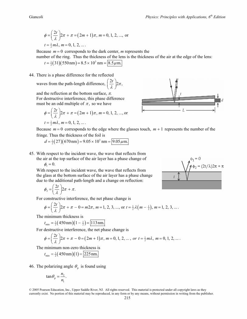
2 31 550nm 8.5 10 nm 8.5 m.t µ= = × = 44. There is a phase difference for the reflected
waves from the path-length difference, 2 2 ,t πλ
⎛ ⎞⎜ ⎟⎝ ⎠
and the reflection at the bottom surface, π. For destructive interference, this phase difference must be an odd multiple of ,π so we have
( )2 2 2 1 , 0, 1, 2, ...,t m mφ π π πλ
⎛ ⎞= + = + =⎜ ⎟⎝ ⎠
or
12 , 0, 1, 2, ...t m mλ= = .
Because 0m = corresponds to the edge where the glasses touch, 1m + represents the number of the fringe. Thus the thickness of the foil is
( )( ) 312 27 670nm 9.05 10 nm 9.05 m.d µ= = × =
45. With respect to the incident wave, the wave that reflects from the air at the top surface of the air layer has a phase change of 1 0.φ = With respect to the incident wave, the wave that reflects from the glass at the bottom surface of the air layer has a phase change due to the additional path-length and a change on reflection:
22 2 .tφ π πλ
⎛ ⎞= +⎜ ⎟⎝ ⎠
For constructive interference, the net phase change is
( )1 12 2
2 2 0 2 , 1, 2, 3, ..., or , 1, 2, 3, ...t m m t m mφ π π π λλ
⎛ ⎞= + − = = = − =⎜ ⎟⎝ ⎠
.
The minimum thickness is ( )( )1 1
min 2 2450nm 1 113nm.t = − = For destructive interference, the net phase change is
( ) 12
2 2 0 2 1 , 0, 1, 2, ... , , 0, 1, 2, ...t m m or t m mφ π π π λλ
⎛ ⎞= + − = + = = =⎜ ⎟⎝ ⎠
.
The minimum non-zero thickness is ( )( )1
min 2 450nm 1 225nm.t = = 46. The polarizing angle pθ is found using
2p
1
tan .nn
θ =

Chapter 24 The Wave Nature of Light
© 2005 Pearson Education, Inc., Upper Saddle River, NJ. All rights reserved. This material is protected under all copyright laws as they currently exist. No portion of this material may be reproduced, in any form or by any means, without permission in writing from the publisher.
216
For an oil–diamond interface, p2.42tan ,1.43
θ = which gives p 59.4 .θ = °
The material does appear to be diamond. 47. With respect to the incident wave, the wave that reflects from the top surface of the alcohol has a phase change of 1 .φ π= With respect to the incident wave, the wave that reflects from the glass at the bottom surface of the alcohol has a phase change due to the additional path-length and a phase change of π on reflection:
2film
2 2 .tφ π πλ
⎛ ⎞= +⎜ ⎟⎝ ⎠
For constructive interference, the net phase change is
( ) ( )11 11 1 1film 1 1 12 2
1film film
2 2 2 , 1, 2, 3, ..., or , 1, 2, 3, ...t m m t m m mnλφ π π π π λ
λ⎛ ⎞ ⎛ ⎞
= + − = = = = =⎜ ⎟ ⎜ ⎟⎜ ⎟ ⎝ ⎠⎝ ⎠.
For destructive interference, the net phase change is
( ) ( )212 2 2 24
2film film
2 2 2 1 , 0, 1, 2, ..., or 2 1 , 0, 1, 2, ...t m m t m mnλφ π π π π
λ⎛ ⎞ ⎛ ⎞
= + − = + = = + =⎜ ⎟ ⎜ ⎟⎝ ⎠ ⎝ ⎠
.
When we combine the two equations, we get
( ) ( ) ( ) ( )( )
21 2 11 11 22 4
film film 1 2
2 1 640nm 52 1 , or 1.25 .2 512nm 4
mm m
n n mλ λ λ
λ+⎛ ⎞ ⎛ ⎞
= + = = = =⎜ ⎟ ⎜ ⎟⎝ ⎠ ⎝ ⎠
Thus we see that 1 2 2,m m= = and the thickness of the film is
( ) ( )( ) ( )11 1
12 2film
640nm2 471nm.
1.36t m
nλ ⎡ ⎤⎛ ⎞
= = =⎢ ⎥⎜ ⎟⎢ ⎥⎝ ⎠ ⎣ ⎦
48. At a distance r from the center of the lens, the thickness of the air space is y, and the phase difference for the reflected waves from the path-length difference and the reflection at the bottom surface is
2 2 .yφ π πλ
⎛ ⎞= +⎜ ⎟⎝ ⎠
For the dark rings, we have
( )2 2 2 1 , 0, 1, 2, ...,y m mφ π π πλ
⎛ ⎞= + = + =⎜ ⎟⎝ ⎠
or
12 , 0, 1, 2, ...y m mλ= = .
Because 0m = corresponds to the dark center, m represents the number of the ring. From the triangle in the diagram, we have ( )22 2 ,r R y R+ − = or 2 22 2 ,r yR y yR= − ≈ when « ,y R which becomes ( )2 1
22 , 0, 1, 2, ...r m R m R mλ λ= = = . When the apparatus is immersed in the liquid, the same analysis holds, if we use the wavelength in the
liquid. If we form the ratio for the two conditions, we get

Giancoli Physics: Principles with Applications, 6th Edition
© 2005 Pearson Education, Inc., Upper Saddle River, NJ. All rights reserved. This material is protected under all copyright laws as they currently exist. No portion of this material may be reproduced, in any form or by any means, without permission in writing from the publisher.
217
2
1 1
2 2
,r nr
λλ
⎛ ⎞= =⎜ ⎟
⎝ ⎠ so
2
2.92cm 1.39.2.48cm
n⎛ ⎞
= =⎜ ⎟⎝ ⎠
49. One fringe shift corresponds to a change in path length of .λ The number of fringe shifts produced by a
mirror movement of L∆ is
2 ;LNλ∆
=
( )32 0.225 10 m
644 ,λ
−×= which gives 76.99 10 m 699nm.λ −= × =
50. One fringe shift corresponds to a change in path length of .λ The number of fringe shifts produced by a
mirror movement of L∆ is
2 ;LNλ∆
=
( )
272 2 ,589nm
L∆= which gives 48.01 10 nm 80.1 m.L µ∆ = × =
51. One fringe shift corresponds to a change in path length of .λ The number of fringe shifts produced by a
mirror movement of L∆ is
2 ;LNλ∆
=
( )9
850 2 ,589 10 m
L−
∆=
× which gives 42.50 10 m 0.250mm.L −∆ = × =
52. One fringe shift corresponds to an effective change in path length of .λ The actual distance has not
changed, but the number of wavelengths in the depth of the cavity has. If the cavity has a depth d, the
number of wavelengths in vacuum is ,dλ
and the number with the gas present is gas
gas
.n dd
λ λ= Because
the light passes through the cavity twice, the number of fringe shifts is
( )gasgas2 2 1 ;
n d d dN nλ λ λ
⎡ ⎤⎛ ⎞ ⎛ ⎞ ⎛ ⎞= − = −⎢ ⎥⎜ ⎟ ⎜ ⎟ ⎜ ⎟⎝ ⎠ ⎝ ⎠⎝ ⎠⎣ ⎦
( )( ) ( )
2
gas9
1.30 10 m236 2 1 ,
610 10 mn
−
−
⎡ ⎤×⎢ ⎥= −
×⎢ ⎥⎣ ⎦ which gives gas 1.00554.n =
53. If the initial intensity is 0 ,I through the two sheets we have 1
1 02 ,I I= 2 21
2 1 02cos cos ,I I Iθ θ= = which gives
2 22 1 12 2
0
cos cos 65 0.089.II
θ= = ° =

Chapter 24 The Wave Nature of Light
© 2005 Pearson Education, Inc., Upper Saddle River, NJ. All rights reserved. This material is protected under all copyright laws as they currently exist. No portion of this material may be reproduced, in any form or by any means, without permission in writing from the publisher.
218
54. Because the light is coming from air to glass, we find the angle from the vertical from p glasstan 1.52,nθ = = which gives p 56.7 .θ = °
55. Because the light is coming from water to diamond, we find the angle from the vertical from
diamondp
water
2.42tan 1.82,1.33
nn
θ = = = which gives p 61.2 .θ = °
56. If 0I is the intensity passed by the first Polaroid, the intensity passed by the second will be 0I when the
two axes are parallel. To reduce the intensity by half, we have 2 1
0 02cos ,I I Iθ= = which gives 45 .θ = ° 57. If the initial intensity is 0 ,I through the two sheets we have 1
1 02 ,I I= 2
2 1 cos ;I I θ= which means
22 12
0
cos .II
θ=
(a) For 2 13
0
,II=
21 13 2 cos θ= gives 35.3 .θ = °
(b) For 2 110
0
,II=
21 110 2 cos θ= gives 63.4 .θ = °
58. If the initial intensity is 0 ,I through the two sheets we have 2
1 0 1cos ;I I θ= 2 2 2
2 1 2 0 1 2cos cos cos ;I I Iθ θ θ= = 2 2
0 0 10.15 cos cos 40 ,I I θ= ° which gives 1 60 .θ = ° 59. Through the successive sheets we have 2
1 0 1cos ,I I θ= 2
2 1 2cos ,I I θ= which gives ( )( )2 2 2 2
2 0 1 2 0 0cos cos cos 19.0 cos 38.0 0.555 .I I I Iθ θ= = ° ° =
Thus the reduction is 44.5%. 60. If the light is coming from water to air, we find Brewster’s angle from
airp
water
1.00tan 0.752,1.33
nn
θ = = = which gives p 36.9 .θ = °
For the refraction at the critical angle from water to air, we have air 1 water 2sin sin ;n nθ θ= ( ) ( ) c1.00 sin 90 1.33 sin ,θ° = which gives c 48.8 .θ = °

Giancoli Physics: Principles with Applications, 6th Edition
© 2005 Pearson Education, Inc., Upper Saddle River, NJ. All rights reserved. This material is protected under all copyright laws as they currently exist. No portion of this material may be reproduced, in any form or by any means, without permission in writing from the publisher.
219
If the light is coming from air to water, we find Brewster’s angle from
waterp
air
1.33tan 1.33,1.00
nn
θ ′ = = = which gives p 53.1 .θ ′ = °
Thus p p 90.0 .θ θ+ ′ = ° 61. When plane-polarized light hits a sheet oriented at an angle ,θ 2
2 1 cos .I I θ= For 45 ,θ = °
22 12
1
cos 45 .II= ° =
So sheets two through five will each reduce the intensity by 12 .
Since the first sheet will reduce the intensity of the unpolarized incident light by 12 as well, the intensity
of the transmitted beam will be ( )51
0 02 0.031 .I I I= =
62. (a) For constructive interference, the path difference is a multiple of the wavelength: sin , 0, 1, 2, 3, ...d m mθ λ= = . We find the location on the screen from tan .y L θ= For small angles, we have sin tan ,θ θ≈ which gives
.m mLy Ld dλ λ⎛ ⎞= =⎜ ⎟
⎝ ⎠
For adjacent bands, 1,m∆ = so we have
;L mydλ∆
∆ =
( )( )( )7
24.0m 5.0 10 m 1
2.0 10 m ,d
−−
×× = which gives 41.0 10 m 0.10mm.d −= × =
(b) For destructive interference, the path difference is given by ( )1
2sin , 0, 1, 2, 3, ...d m mθ λ= + = . Again we find the location on the screen from tan ,y L θ= and again we use sin tan ,θ θ≈ this time to obtain
( )1
2 .m L
yd
λ+=
We are told that
( ) ( )1 1
2 12 25 4;
L Ld d
λ λ+ +=
( ) ( )( )71 122 25 4 5.0 10 m ,λ −+ = + ×
which gives 72 4.1 10 m.λ −= ×

Chapter 24 The Wave Nature of Light
© 2005 Pearson Education, Inc., Upper Saddle River, NJ. All rights reserved. This material is protected under all copyright laws as they currently exist. No portion of this material may be reproduced, in any form or by any means, without permission in writing from the publisher.
220
63. The wavelength of the signal is
( )( )
8
6
3.00 10 m s4.00m.
75 10 Hzvf
λ×
= = =×
(a) There is a phase difference between the direct and
reflected signals from the path difference, 2 ,h πλ
⎛ ⎞⎜ ⎟⎝ ⎠
and the reflection, π. The total phase difference is
( )( ) ( )118m
2 2 30 2 .4.00m
hφ π π π π πλ
⎡ ⎤⎛ ⎞= + = + =⎢ ⎥⎜ ⎟⎝ ⎠ ⎢ ⎥⎣ ⎦
Thus the interference is constructive. (b) When the plane is 22 m closer to the receiver, the phase difference is
( ) 2h y
φ π πλ
⎡ − ⎤= +⎢ ⎥⎣ ⎦
( )( ) ( )118m 22m
2 24 2 .4.00m
π π π π⎡ ⎤−
= + = +⎢ ⎥⎢ ⎥⎣ ⎦
Thus the interference is destructive. 64. We find the angles for the first order from sin ;d mθ λ λ= =
7h5
1 sin 6.56 10 m,3.00 10 lines m
θ −= ××
which gives hsin 0.197,θ = so h 11.3 ;θ = °
7n5
1 sin 6.50 10 m,3.00 10 lines m
θ −= ××
which gives nsin 0.195,θ = so n 11.2 ;θ = °
7a5
1 sin 6.97 10 m,3.00 10 lines m
θ −= ××
which gives asin 0.209,θ = so a 12.1 .θ = °
65. For constructive interference, the path difference is a multiple of the wavelength: sin , 0, 1, 2, 3, ...d m mθ λ= = . We find the location on the screen from tan .y L θ= For small angles, we have sin tan ,θ θ≈ which gives
.m mLy Ld dλ λ⎛ ⎞= =⎜ ⎟
⎝ ⎠
For the second-order fringes we have
11
2 ;Lydλ
=
22
2 .Lydλ
=

Giancoli Physics: Principles with Applications, 6th Edition
© 2005 Pearson Education, Inc., Upper Saddle River, NJ. All rights reserved. This material is protected under all copyright laws as they currently exist. No portion of this material may be reproduced, in any form or by any means, without permission in writing from the publisher.
221
When we subtract the two equations, we get
( )1 2 1 22 ;Ly y yd
λ λ⎛ ⎞∆ = − = −⎜ ⎟⎝ ⎠
( )( ) ( )3
23
2 1.70m1.33 10 m 590nm ,
0.60 10 mλ−
−
⎡ ⎤⎢ ⎥× = −
×⎢ ⎥⎣ ⎦ which gives 2 355nm.λ =
66. The wavelength of the signal is
( )( )
8
6
3.00 10 m s2.94m.
102.1 10 Hzvf
λ×
= = =×
Because measurements are made far from the antennae, we can use the analysis for the double slit. For constructive interference, the path difference is a multiple of the wavelength: sin , 0, 1, 2, 3, ... ;d m mθ λ= = ( ) ( )( )1max8.0m sin 1 2.94m ,θ = which gives 1max 22 ;θ = ° ( ) ( )( )2max8.0m sin 2 2.94m ,θ = which gives 2max 47 ;θ = ° ( ) ( )( )3max8.0m sin 3 2.94m ,θ = which gives 3maxsin 1,θ > so there is no third maximum. Because the interference pattern will be symmetrical above and below the midline and on either side of
the antennae, the angles for maxima are 22°, 47°, 133°, 158° above and below the midline. For destructive interference, the path difference is an odd multiple of half a wavelength: ( )1
2sin , 1, 2, 3, ... ;d m mθ λ= − = or
( ) ( )( )11min 28.0m sin 1 2.94m ,θ = − which gives 1min 11 ;θ = °
( ) ( )( )12min 28.0m sin 2 2.94m ,θ = − which gives 2min 33 ;θ = °
( ) ( )( )13min 28.0m sin 3 2.94m ,θ = − which gives 3min 67 ;θ = °
( ) ( )( )14min 28.0m sin 4 2.94m ,θ = − which gives 4minsin 1,θ > so there is no fourth minimum.
Because the interference pattern will be symmetrical above and below the midline and on either side of the antennae, the angles for minima are 11°, 33°, 67°, 113°, 147°, 169° above and below the midline.
67. The wavelength of the sound is
( )( )343m s
0.457 m.750Hz
vf
λ = = =
We find the angles of the minima from sin , 1, 2, 3, ... ;D m mθ λ= = ( ) ( )( )10.88m sin 1 0.457m ,θ = which gives 1sin 0.520,θ = so 1 31 ;θ = ° ( ) ( )( )20.88m sin 2 0.457 m ,θ = which gives 2sin 1.04,θ = so there is no 2.θ Thus the whistle would not be heard clearly at angles of 31° on either side of the normal.

Chapter 24 The Wave Nature of Light
© 2005 Pearson Education, Inc., Upper Saddle River, NJ. All rights reserved. This material is protected under all copyright laws as they currently exist. No portion of this material may be reproduced, in any form or by any means, without permission in writing from the publisher.
222
68. The path difference between the top and bottom of the slit for the incident wave is isin .D θ The path difference between the top and bottom of the slit for the diffracted wave is sin .D θ When i ,θ θ= the net path difference is zero, and there will be constructive interference. There is a central maximum at 30 .θ = ° When the net path difference is a multiple of a wavelength, there will be minima given by ( ) ( )isin sin , 1, 2, ...,D D m mθ θ λ− = = ± ± or
sin sin 30 ,mDλθ ⎛ ⎞= ° − ⎜ ⎟
⎝ ⎠ where 1, 2, ...m = ± ± .
69. The lines act like a grating. Assuming the first order, we find the separation of the lines from sin ;d mθ λ= ( )( )9sin51 1 460 10 m ,d −° = × which gives 75.9 10 m 590nm.d −= × =
70. Because the angle increases with wavelength, to miss a complete order we use the smallest wavelength.
The maximum angle is 90°. We find the slit separation from sin ;d mθ λ= ( )( )9sin90 2 400 10 m ,d −° = × which gives 7 58.00 10 m 8.00 10 cm.d − −= × = ×
The number of lines/cm is
( )5
1 1 12,500 lines cm.8.00 10 cmd −
= =×
71. Because the angle increases with wavelength, we compare the maximum angle for the second order with
the minimum angle for the third order:
sin ,d mθ λ= or sin ;dλθ =
( )( )2max
2 750nmsin ;
dθ =
( )( )3min
3 400nmsin .
dθ =
When we divide the two equations, we get
( )( )
3min
2max
1200nmsin 0.8.sin 1500nm
θθ
= =
Because the value of the sine increases with angle, this means 3min 2max ,θ θ< so the orders overlap. To determine the overlap, we find the second-order wavelength that coincides with 3min :θ ( ) ( )( )22 3 400nm ,λ = which gives 2 600nm.λ = We find the third-order wavelength that coincides with 2maxθ from ( )( ) ( ) 32 750nm 3 ,λ= which gives 3 500nm.λ = Thus 600 nm to 750 nm of the second order overlaps with 400 nm to 500 nm of the third order.

Giancoli Physics: Principles with Applications, 6th Edition
© 2005 Pearson Education, Inc., Upper Saddle River, NJ. All rights reserved. This material is protected under all copyright laws as they currently exist. No portion of this material may be reproduced, in any form or by any means, without permission in writing from the publisher.
223
72. We find the angles for the first order from the distances:
( )( )
11 1
3.32cmtan 0.0553, so 3.17 ;
60.0cmyL
θ θ= = = = °
( )( )
22 2
3.71cmtan 0.0618, so 3.54 .
60.0cmyL
θ θ= = = = °
We find the separation of lines from 1 1sin ;d mθ λ= ( )( )9sin3.17 1 589 10 m ,d −° = × which gives 5 31.066 10 m 1.066 10 cm.d − −= × = ×
For the second wavelength we have 2 2sin ;d mθ λ= ( ) ( )5
21.06 10 m sin 3.54 1 ,λ−× ° = which gives 72 6.58 10 m 658nm.λ −= × =
The number of lines/cm is
( )3
1 1 938 lines cm.1.066 10 cmd −
= =×
73. We find the angles for the first order from sin ;d mθ λ λ= =
( ) ( )2 7
11 10 m cm sin 4.6 10 m,
8600 lines cmθ− −⎡ ⎤
= ×⎢ ⎥⎢ ⎥⎣ ⎦
which gives 1sin 0.396,θ = so 1 23.3 ;θ = °
( ) ( )2 7
21 10 m cm sin 6.8 10 m,
8600 lines cmθ− −⎡ ⎤
= ×⎢ ⎥⎢ ⎥⎣ ⎦
which gives 2sin 0.585,θ = so 2 35.8 .θ = °
The distances from the central white line on the screen are ( )1 1tan 2.5m tan 23.3 1.1m;y L θ= = ° = ( )2 2tan 2.5m tan 35.8 1.8m.y L θ= = ° = Thus the separation of the lines is 2 1 1.8m 1.1m 0.7 m.y y− = − = 74. We equate a path difference of one wavelength with a phase difference of 2 .π With respect to the incident wave, the wave that reflects at the top surface of the film has a phase change of 1 .φ π= If we assume that the film has an index less than glass, the wave that reflects from the glass has a phase change due to the additional path-length and a phase change on reflection:
2film
2 2 .tφ π πλ
⎛ ⎞= +⎜ ⎟⎝ ⎠
For destructive interference, the net phase change is
( ) ( ) ( )1 1 1 1 1film2 2 2 2 2
film
2 2 2 , 1, 2, ..., or , 1, 2, ...t m m t m m mnλφ π π π π λ
λ⎛ ⎞ ⎛ ⎞= + − = − = = − = − =⎜ ⎟ ⎜ ⎟
⎝ ⎠⎝ ⎠.
Chapter 24 The Wave Nature of Light
© 2005 Pearson Education, Inc., Upper Saddle River, NJ. All rights reserved. This material is protected under all copyright laws as they currently exist. No portion of this material may be reproduced, in any form or by any means, without permission in writing from the publisher.
224
For the minimum thickness, 1,m = we have
( )( ) ( )1 1
2 2
600nm150nm 1 ,
n⎡ ⎤
= −⎢ ⎥⎢ ⎥⎣ ⎦
which gives 1,n = so no film with glassn n< is possible.
If we assume that the film has an index greater than glass, the wave that reflects from the glass has a phase change due to the additional path-length and no phase change on reflection:
2film
2 2 0.tφ πλ
⎛ ⎞= +⎜ ⎟⎝ ⎠
For destructive interference, the net phase change is
( )1 1 1film2 2 2
film
2 2 2 , 1, 2, ... , or , 1, 2, ...t mm m t m mnλφ π π π λ
λ⎛ ⎞ ⎛ ⎞= − = − = = = =⎜ ⎟ ⎜ ⎟
⎝ ⎠⎝ ⎠.
For the minimum thickness, m = 1, we have
( )( )12
1 600nm150nm ,
n⎛ ⎞
= ⎜ ⎟⎝ ⎠
which gives 2.00.n =
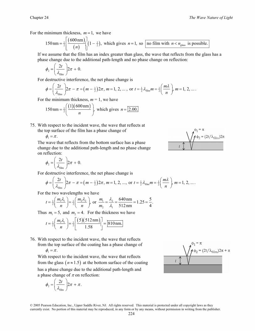
75. With respect to the incident wave, the wave that reflects at the top surface of the film has a phase change of 1 .φ π= The wave that reflects from the bottom surface has a phase change due to the additional path-length and no phase change on reflection:
2film
2 2 0.tφ πλ
⎛ ⎞= +⎜ ⎟⎝ ⎠
For destructive interference, the net phase change is
( )1 1 1film2 2 2
film
2 2 2 , 1, 2, ..., or , 1, 2, ...t mm m t m mnλφ π π π λ
λ⎛ ⎞ ⎛ ⎞= − = − = = = =⎜ ⎟ ⎜ ⎟
⎝ ⎠⎝ ⎠.
For the two wavelengths we have
1 1 2 2 1 21 12 2
2 1
640nm 5, or 1.25 .512nm 4
m m mtn n mλ λ λ
λ⎛ ⎞ ⎛ ⎞= = = = = =⎜ ⎟ ⎜ ⎟⎝ ⎠ ⎝ ⎠
Thus 1 5,m = and 2 4.m = For the thickness we have
( )( )1 11 12 2
5 512nm810nm.
1.58mt
nλ ⎡ ⎤⎛ ⎞= = =⎢ ⎥⎜ ⎟
⎝ ⎠ ⎣ ⎦
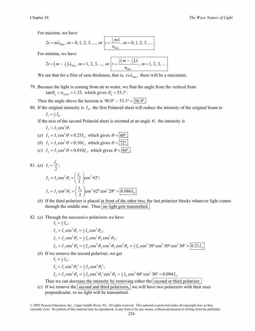
76. With respect to the incident wave, the wave that reflects from the top surface of the coating has a phase change of 1 .φ π= With respect to the incident wave, the wave that reflects from the glass ( )1.5n ≈ at the bottom surface of the coating has a phase change due to the additional path-length and a phase change of π on reflection:
2film
2 2 .tφ π πλ
⎛ ⎞= +⎜ ⎟⎝ ⎠
Giancoli Physics: Principles with Applications, 6th Edition
© 2005 Pearson Education, Inc., Upper Saddle River, NJ. All rights reserved. This material is protected under all copyright laws as they currently exist. No portion of this material may be reproduced, in any form or by any means, without permission in writing from the publisher.
225
For destructive interference, this phase difference must be an odd multiple of ,π so we have
( ) ( )1film4
film
2 2 2 1 , 0, 1, 2, ..., or 2 1 , 0, 1, 2, ...t m m t m mφ π π π π λλ
⎛ ⎞= + − = + = = + =⎜ ⎟⎝ ⎠
.
Thus the minimum thickness is
1min 4 .t
nλ
=
(a) For the blue light we get
( )( )
1min 4
450nm81.5nm.
1.38t = =
(b) For the red light we get
( )( )
1min 4
700nm127nm.
1.38t = =
77. As explained in Example 24-8, the 12 - cycle phase change at the lower surface means that maximum
destructive interference will occur when the thickness t is such that 2 , 0, 1, 2, ...t m mλ= = . We set 1m = to find the smallest nonzero value of t:
640nm 320nm.2 2
t λ= = =
As also explained in Example 24-8, maximum constructive interference will occur when ( )1
22 , 0, 1, 2, ...t m mλ= + = . We set 0m = to find the smallest value of t:
640nm 160nm.4 4
t λ= = =
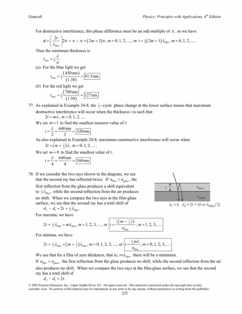
78. If we consider the two rays shown in the diagram, we see that the second ray has reflected twice. If film glass ,n n< the first reflection from the glass produces a shift equivalent to 1
film2 ,λ while the second reflection from the air produces no shift. When we compare the two rays at the film-glass surface, we see that the second ray has a total shift of 1
2 1 film22 .d d t λ− = + For maxima, we have
( )1 1
2 21film film2
film
2 , 1, 2, 3, ..., or , 1, 2, 3, ... .m
t m m t mn
λλ λ
−+ = = = =
For minima, we have
( )121 1
film film2 2film
2 , 0, 1, 2, 3, ..., or , 0, 1, 2, 3, ... .m
t m m t mn
λλ λ+ = + = = =
We see that for a film of zero thickness, that is, film« ,t λ there will be a minimum. If film glass ,n n> the first reflection from the glass produces no shift, while the second reflection from the air
also produces no shift. When we compare the two rays at the film-glass surface, we see that the second ray has a total shift of
2 1 2 .d d t− =
Chapter 24 The Wave Nature of Light
© 2005 Pearson Education, Inc., Upper Saddle River, NJ. All rights reserved. This material is protected under all copyright laws as they currently exist. No portion of this material may be reproduced, in any form or by any means, without permission in writing from the publisher.
226
For maxima, we have
12
filmfilm
2 , 0, 1, 2, 3, ..., or , 0, 1, 2, 3, ... .m
t m m t mn
λλ= = = =
For minima, we have
( ) ( )1 12 21
film2film
2 , 1, 2, 3, ..., or , 1, 2, 3, ... .m
t m m t mn
λλ
−= − = = =
We see that for a film of zero thickness, that is, film« ,t λ there will be a maximum. 79. Because the light is coming from air to water, we find the angle from the vertical from p watertan 1.33,nθ = = which gives p 53.1 .θ = °
Thus the angle above the horizon is 90.0 53.1 36.9 .° − ° = ° 80. If the original intensity is 0 ,I the first Polaroid sheet will reduce the intensity of the original beam to 1
1 02 .I I= If the axis of the second Polaroid sheet is oriented at an angle ,θ the intensity is 2
2 1 cos .I I θ= (a) 2
2 1 1cos 0.25 ,I I Iθ= = which gives 60 .θ = ° (b) 2
2 1 1cos 0.10 ,I I Iθ= = which gives 72 .θ = ° (c) 2
2 1 1cos 0.010 ,I I Iθ= = which gives 84 .θ = °
81. (a) 01 ;
2II =
2 202 1 1cos cos 62 ;
2II I θ ⎛ ⎞= = °⎜ ⎟
⎝ ⎠
2 2 203 2 2 0cos cos 62 cos 28 0.086 .
2II I Ιθ ⎛ ⎞= = ° ° =⎜ ⎟
⎝ ⎠
(b) If the third polarizer is placed in front of the other two, the last polarizer blocks whatever light comes through the middle one. Thus no light gets transmitted. 82. (a) Through the successive polarizers we have 1
1 02 ;I I= 2 21
2 1 2 0 22cos cos ;I I Iθ θ= = 2 2 21
3 2 3 0 2 32cos cos cos ;I I Iθ θ θ= =
2 2 2 2 2 2 21 14 3 4 0 2 3 4 0 02 2cos cos cos cos cos 30 cos 30 cos 30 0.21 .I I I I Iθ θ θ θ= = = ° ° ° =
(b) If we remove the second polarizer, we get 1
1 02 ;I I= 2 21
3 1 3 0 32cos cos ;I I Iθ θ= ′ = ′ 2 2 2 2 21 1
4 3 4 0 3 4 0 02 2cos cos cos cos 60 cos 30 0.094 .I I I I Iθ θ θ= = ′ = ° ° = Thus we can decrease the intensity by removing either the second or third polarizer. (c) If we remove the second and third polarizers, we will have two polarizers with their axes perpendicular, so no light will be transmitted.
Giancoli Physics: Principles with Applications, 6th Edition
© 2005 Pearson Education, Inc., Upper Saddle River, NJ. All rights reserved. This material is protected under all copyright laws as they currently exist. No portion of this material may be reproduced, in any form or by any means, without permission in writing from the publisher.
227
83. We will find the width of the central maximum by first finding the angular half-width ,θ using
9
5630 10 msin 6.30 10 .0.010mD
λθ−
−×= = = ×
We find the distance on the Moon’s surface from tan .y L θ= For small angles, we have sin tan ,θ θ≈ which gives 8 5 4sin (3.80 10 m)(6.30 10 )2.394 10 m.y L θ −= = × × × Thus the width of the central maximum is 42 4.788 10 m 47.9km.y = × =
84. If the original intensity is 0 ,I the first polarizers will reduce the intensity to 1
1 02 .I I= Each subsequent polarizer oriented at an angle θ to the preceding one will reduce the intensity as given by the equation 2
i 1 iI I cos .θ+ = So for n polarizers (including the first one), ( )( )n 121
f 02I I cos .θ−
=
We seek n such that ( )( ) 121 1
0 04 2 cos 10 ;n
I I−
= °
( )2 212 cos10 ;n−= °
( ) ( )ln 2 2 1 ln cos10 ,n− = − ° which gives 23.6.n = So 24 polarizers are needed for the intensity to drop below 1
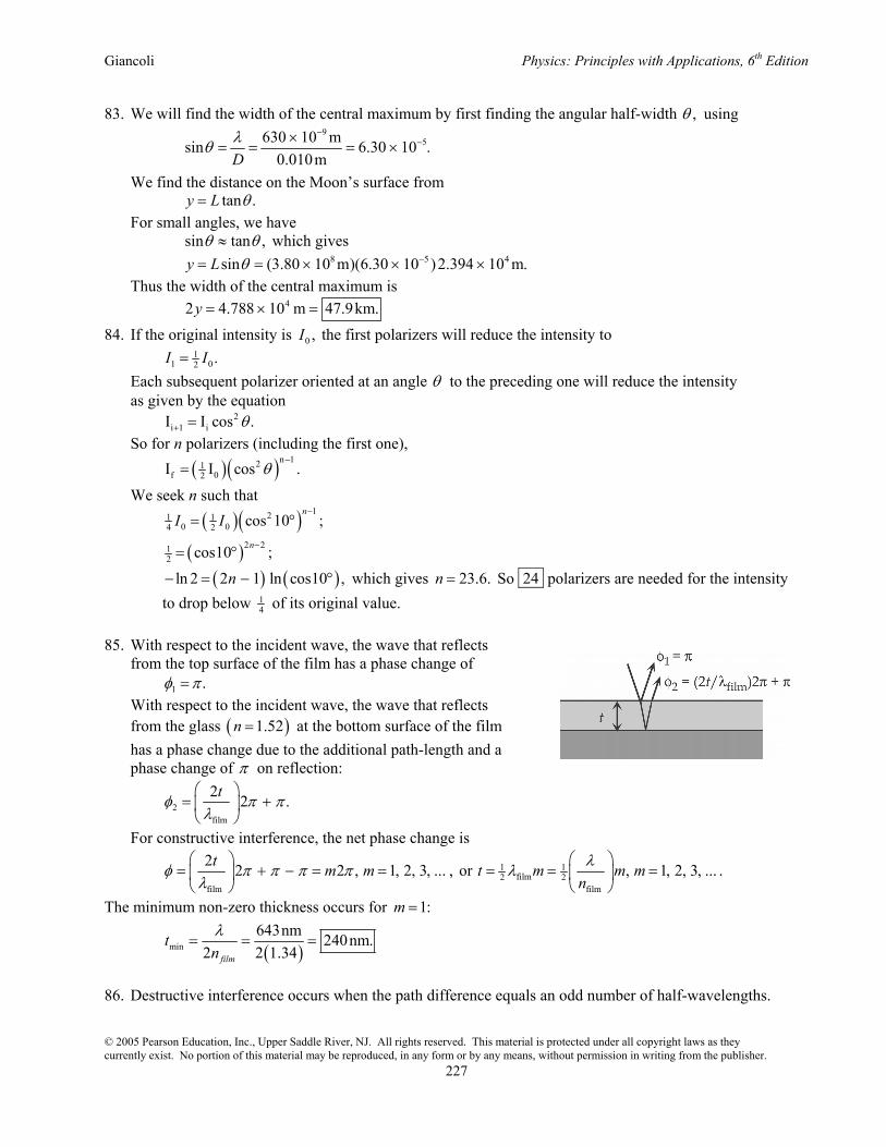
4 of its original value. 85. With respect to the incident wave, the wave that reflects from the top surface of the film has a phase change of 1 .φ π= With respect to the incident wave, the wave that reflects from the glass ( )1.52n = at the bottom surface of the film has a phase change due to the additional path-length and a phase change of π on reflection:
2film
2 2 .tφ π πλ
⎛ ⎞= +⎜ ⎟⎝ ⎠
For constructive interference, the net phase change is
1 1film2 2
film film
2 2 2 , 1, 2, 3, ... , or , 1, 2, 3, ...t m m t m m mnλφ π π π π λ
λ⎛ ⎞ ⎛ ⎞
= + − = = = = =⎜ ⎟ ⎜ ⎟⎝ ⎠ ⎝ ⎠
.
The minimum non-zero thickness occurs for 1:m =
( )min
643nm 240nm.2 2 1.34film
tnλ
= = =
86. Destructive interference occurs when the path difference equals an odd number of half-wavelengths.

Chapter 24 The Wave Nature of Light
© 2005 Pearson Education, Inc., Upper Saddle River, NJ. All rights reserved. This material is protected under all copyright laws as they currently exist. No portion of this material may be reproduced, in any form or by any means, without permission in writing from the publisher.
228
We write the equation
( ) ( )22 12175m , 0, 1, 2, 3, ...y y m mλ+ − = + = .
The wavelength λ is
8
6
3.00 10 m s 50m.6.0 10 Hz
cf
λ ×= = =
×
Solving:
( ) ( )( )22 12175m 50m ;y y m+ = + +
( ) ( )( ) ( )( ) 222 2 1 12 2175m 2 50m 50m ;y y m y m⎡ ⎤+ = + + + +⎣ ⎦
( ) ( )( )
( )( )
22 12
12
175m 50m2 50m
my
m⎡ ⎤− +⎣ ⎦=+
For 0, 1, 2, and 3,m = y equals 600 m, 167 m, 60 m, and 0, respectively. The first three points on the y axis at which there is destructive interference are at y 0,60m, and 167m.= 87. (a) For the refraction at the first surface, we have air sin sin ;a bn nθ θ= ( ) ( ) 11.00 sin 45 1.652 sin ,bθ° = which gives 1 25.34 ;bθ = ° ( ) ( ) 21.00 sin 45 1.619 sin ,bθ° = which gives 2 25.90 .bθ = ° We find the angle of incidence at the second surface from ( ) ( )90 90 180 ,b c Aθ θ° − + ° − + = ° which gives 1 1 60.00 25.34 34.66 ;c bAθ θ= − = ° − ° = ° 2 2 60.00 25.90 34.10c bAθ θ= − = ° − ° = ° For the refraction at the second surface, we have airsin sin ;c dn nθ θ= ( ) ( ) 11.652 sin 34.66 1.00 sin ,dθ° = which gives 1 69.96 ;dθ = ° ( ) ( ) 21.619 sin34.10 1.00 sin ,dθ° = which gives 2 65.20 .dθ = °
The angle between the emerging beams is 69.96 65.20 4.8 .° − ° = ° (b) We find the angles for the first order from sin ;d mθ λ λ= =
( )2 91
1 10 m cm sin 420 10 m,6200lines cm
θ− −= × which gives 1 1sin 0.2604, so 15.09 .θ θ= = °
( )2 92
1 10 m cm sin 650 10 m,6200lines cm
θ− −= × which gives 2 2sin 0.4030, so 23.77 .θ θ= = °
The angle between the first-order maxima is 23.77 15.09 8.7 .° − ° = ° 88. We use the lensmaker’s equation to find the two focal lengths:
( )1 2
1 1 11 .nf R R
⎛ ⎞= − +⎜ ⎟
⎝ ⎠

Giancoli Physics: Principles with Applications, 6th Edition
© 2005 Pearson Education, Inc., Upper Saddle River, NJ. All rights reserved. This material is protected under all copyright laws as they currently exist. No portion of this material may be reproduced, in any form or by any means, without permission in writing from the publisher.
229
With 1R = ∞ and 2 18.4cm,R = this gives
18.4cm ;1
fn
=−
red18.4cm 36.04cm;
1.5106 1f = =
−
yellow18.4cm 35.21cm.
1.5226 1f = =
−
Now we find the two image distances.
o i
1 1 1 ;d d f
+ =
i-red
1 1 1 ,66.0cm 36.04cmd
+ = which gives i-red 79.4cm.d =
i-yellow
1 1 1 ,66.0cm 35.21cmd
+ = which gives i-yellow 75.5cm.d =