Embed Size (px)
Citation preview
Chapter 21Fundamentals of Machining
Introduction to Cutting - Common Introduction to Cutting - Common Machining OperationsMachining Operations
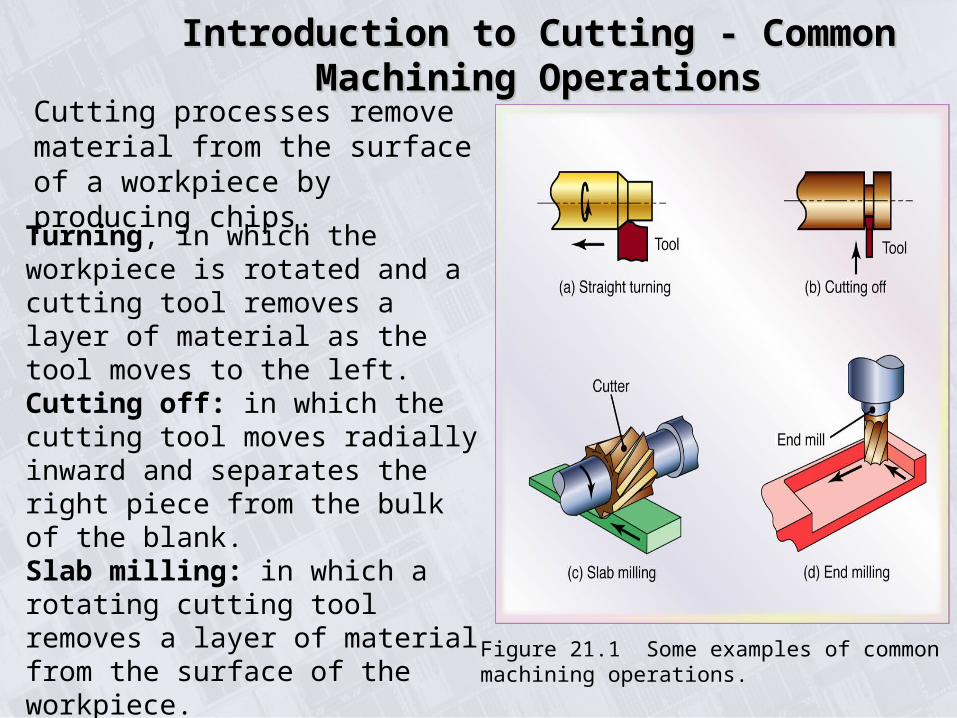
Figure 21.1 Some examples of common machining operations.
Cutting processes remove material from the surface of a workpiece by producing chips.
Turning, in which the workpiece is rotated and a cutting tool removes a layer of material as the tool moves to the left.Cutting off: in which the cutting tool moves radially inward and separates the right piece from the bulk of the blank.Slab milling: in which a rotating cutting tool removes a layer of material from the surface of the workpiece.End milling: in which a rotating cutter travels along a certain depth in the work-piece and produces a cavity.
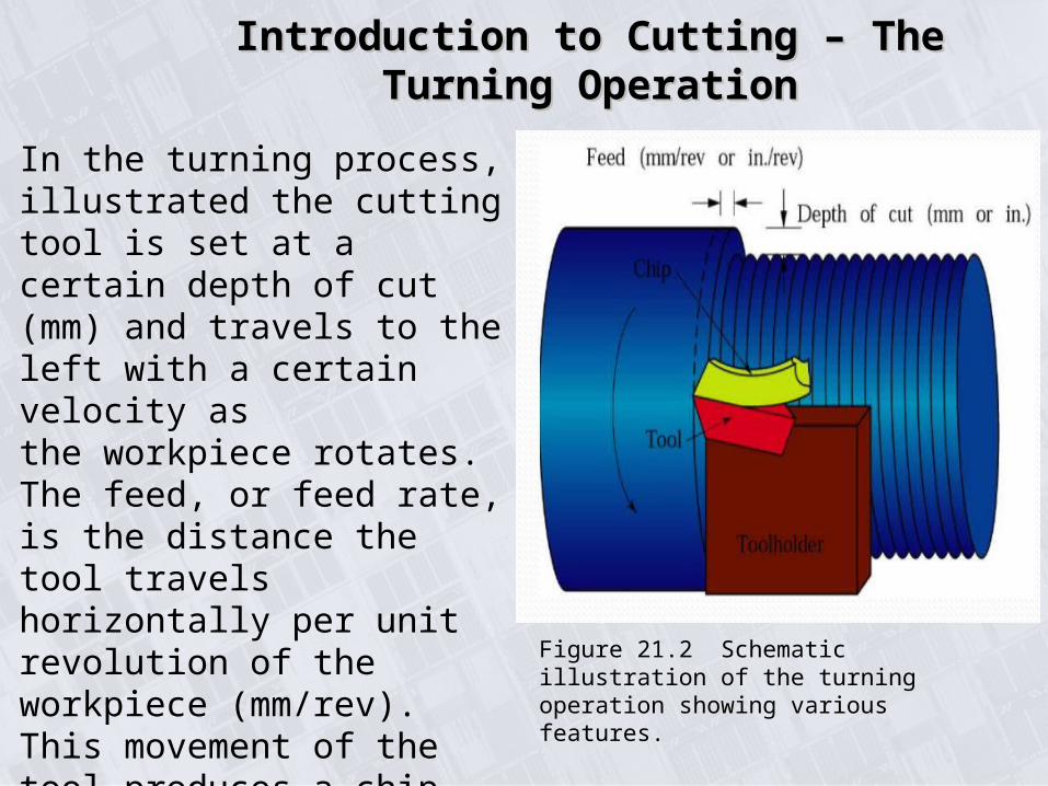
Figure 21.2 Schematic illustration of the turning operation showing various features.
In the turning process, illustrated the cutting tool is set at a certain depth of cut (mm) and travels to the left with a certain velocity asthe workpiece rotates. The feed, or feed rate, is the distance the tool travels horizontally per unit revolution of the workpiece (mm/rev). This movement of thetool produces a chip, which moves up the face of the tool.
Introduction to Cutting – The Turning Introduction to Cutting – The Turning OperationOperation
Two-Dimensional Two-Dimensional Cutting ProcessCutting Process
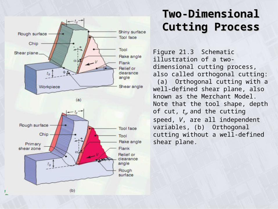
Figure 21.3 Schematic illustration of a two-dimensional cutting process, also called orthogonal cutting: (a) Orthogonal cutting with a well-defined shear plane, also known as the Merchant Model. Note that the tool shape, depth of cut, to, and the cutting speed, V, are all independent variables, (b) Orthogonal cutting without a well-defined shear plane.
Introduction to cuttingIntroduction to cutting
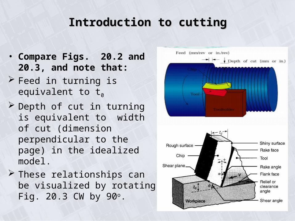
• Compare Figs. 20.2 and 20.3, and note that:
Feed in turning is equivalent to t0
Depth of cut in turning is equivalent to width of cut (dimension perpendicular to the page) in the idealized model.
These relationships can be visualized by rotating Fig. 20.3 CW by 90o.

Factors Influencing Machining OperationsFactors Influencing Machining Operations
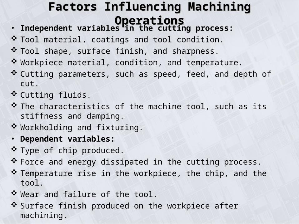
• Independent variables in the cutting process: Tool material, coatings and tool condition. Tool shape, surface finish, and sharpness. Workpiece material, condition, and temperature. Cutting parameters, such as speed, feed, and depth of cut. Cutting fluids. The characteristics of the machine tool, such as its stiffness and
damping. Workholding and fixturing.
• Dependent variables: Type of chip produced. Force and energy dissipated in the cutting process. Temperature rise in the workpiece, the chip, and the tool. Wear and failure of the tool. Surface finish produced on the workpiece after machining.
Factors Influencing Machining OperationsFactors Influencing Machining Operations
Orthogonal cuttingOrthogonal cuttingChip Formation by ShearingChip Formation by Shearing
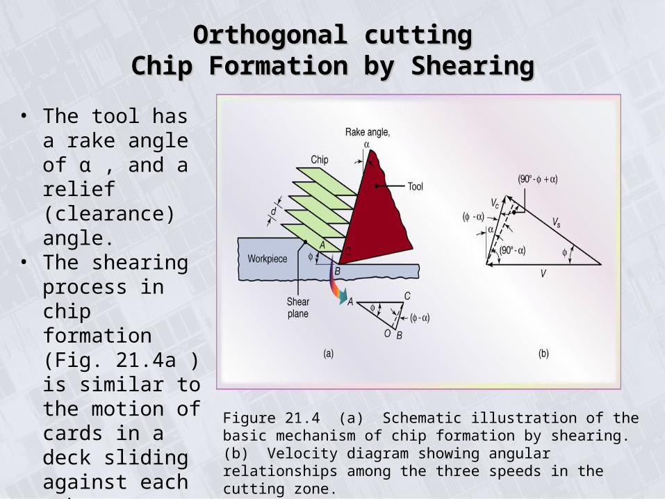
Figure 21.4 (a) Schematic illustration of the basic mechanism of chip formation by shearing. (b) Velocity diagram showing angular relationships among the three speeds in the cutting zone.
• The tool has a rake angle of α , and a relief (clearance) angle.
• The shearing process in chip formation (Fig. 21.4a ) is similar to the motion of cards in a deck sliding against each other.
THE MECHANICS OF CHIP FORMATION- THE MECHANICS OF CHIP FORMATION- ORTHOGONAL CUTTINGORTHOGONAL CUTTING
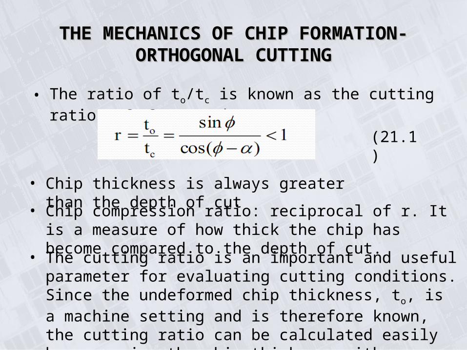
• The ratio of to/tc is known as the cutting ratio, r, expressed as:
• Chip thickness is always greater than the depth of cut
• Chip compression ratio: reciprocal of r. It is a measure of how thick the chip has become compared to the depth of cut.
(21.1)
• The cutting ratio is an important and useful parameter for evaluating cutting conditions. Since the undeformed chip thickness, to, is a machine setting and is therefore known, the cutting ratio can be calculated easily by measuring the chip thickness with a micrometer.
THE MECHANICS OF CHIP FORMATION- THE MECHANICS OF CHIP FORMATION- ORTHOGONAL CUTTINGORTHOGONAL CUTTING
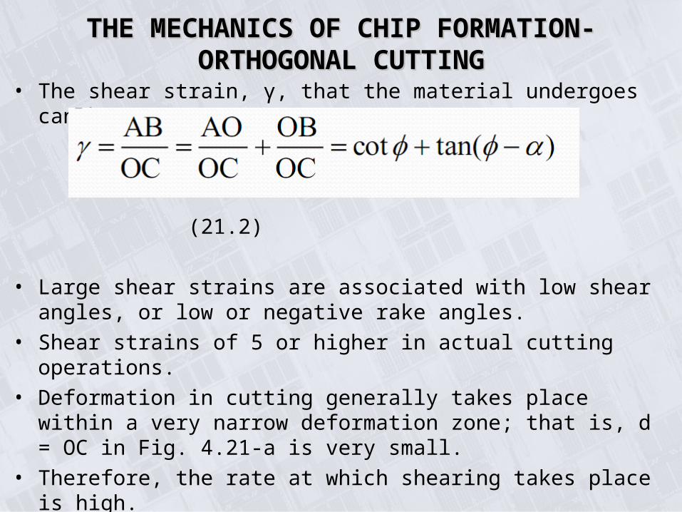
• The shear strain, γ, that the material undergoes can be express as:
(21.2)
• Large shear strains are associated with low shear angles, or low or negative rake angles.
• Shear strains of 5 or higher in actual cutting operations.
• Deformation in cutting generally takes place within a very narrow deformation zone; that is, d = OC in Fig. 4.21-a is very small.
• Therefore, the rate at which shearing takes place is high.
• Shear angle influences force and power requirements, chip thickness, and temperature.
• Consequently, much attention has been focused on determining the relationships between the shear angle and workpiece material properties and cutting process variables.

THE MECHANICS OF CHIP FORMATION- THE MECHANICS OF CHIP FORMATION- ORTHOGONAL CUTTINGORTHOGONAL CUTTING
• Assuming that the shear angle adjusts itself to minimize the cutting force, or that the shear plane is a plane of maximum shear stress.
(21.3)
β is the friction angle and is related to the coefficient of friction, μ, at the tool – chip interface (rake face):
o From Eq (21.3), as the rake angle decreases and / or the friction at the tool – chip interface increases, the shear angle decreases and the chip becomes thicker,
o Thicker chips mean more energy dissipation because the shear strain is higher (Eq. (21.2))
o Because work done during cutting is converted into heat, temperature rise is also higher.
THE MECHANICS OF CHIP FORMATION- THE MECHANICS OF CHIP FORMATION- ORTHOGONAL CUTTINGORTHOGONAL CUTTING
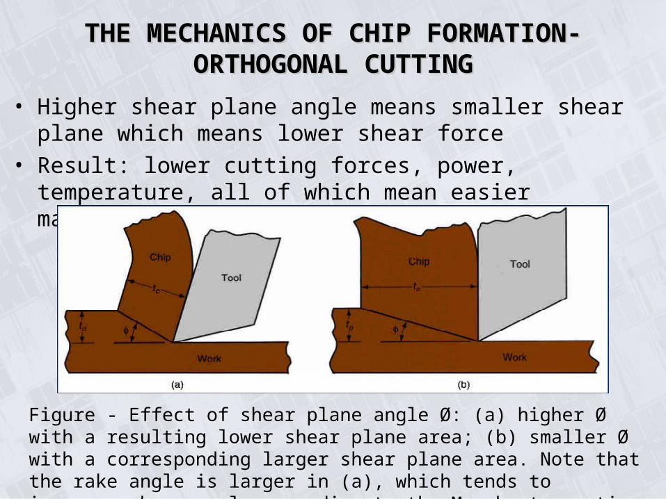
• Higher shear plane angle means smaller shear plane which means lower shear force
• Result: lower cutting forces, power, temperature, all of which mean easier machining
Figure - Effect of shear plane angle Ø: (a) higher Ø with a resulting lower shear plane area; (b) smaller Ø with a corresponding larger shear plane area. Note that the rake angle is larger in (a), which tends to increase shear angle according to the Merchant equation

THE MECHANICS OF CHIP FORMATION- THE MECHANICS OF CHIP FORMATION- ORTHOGONAL CUTTINGORTHOGONAL CUTTING
• From Fig. 20.3, since chip thickness is greater than the depth of cut, the velocity of the chip, Vc, has to be lower than the cutting speed, V.
• Conservation of mass:
(21.5)
(21.6)
• Vs is the velocity at which shearing
takes place in the shear plane.
• From the velocity diagram (Fig. 20.4b), we obtain the
TYPES OF CHIPS PRODUCED IN METAL-TYPES OF CHIPS PRODUCED IN METAL-CUTTINGCUTTING
1. Continuous2. Built-up Edge3. Serrated or Segmented4. Discontinuous
A chip has two surfaces:1.One that is in contact with the tool face (rake face). This surface is shiny, or burnished.2.The other from the original surface of the workpiece. This surface does not come into contact with any solid body. This surface has a jagged, rough appearance (Fig. 20.3), which is caused by the shearing mechanism shown in fig. 20.4a.
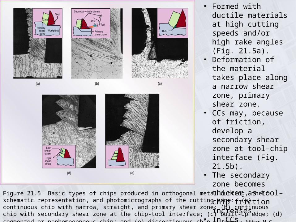
Figure 21.5 Basic types of chips produced in orthogonal metal cutting, their schematic representation, and photomicrographs of the cutting zone: (a) continuous chip with narrow, straight, and primary shear zone; (b) continuous chip with secondary shear zone at the chip-tool interface; (c) built-up edge; (d) segmented or nonhomogeneous chip; and (e) discontinuous chip. Source: After M.C. Shaw, P.K. Wright, and S. Kalpakjian.
• Formed with ductile materials at high cutting speeds and/or high rake angles (Fig. 21.5a).
• Deformation of the material takes place along a narrow shear zone, primary shear zone.
• CCs may, because of friction, develop a secondary shear zone at tool–chip interface (Fig. 21.5b).
• The secondary zone becomes thicker as tool–chip friction increases.
• In CCs, deformation may also take place along a wide primary shear zone with curved boundaries (Fig. 21.3b).
TYPES OF CHIPS PRODUCED IN METAL -TYPES OF CHIPS PRODUCED IN METAL -CUTTING: CONTINUOUS CHIPS (CC)CUTTING: CONTINUOUS CHIPS (CC)
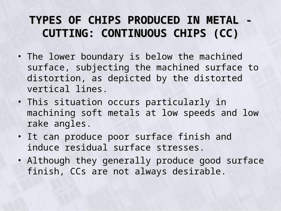
• The lower boundary is below the machined surface, subjecting the machined surface to distortion, as depicted by the distorted vertical lines.
• This situation occurs particularly in machining soft metals at low speeds and low rake angles.
• It can produce poor surface finish and induce residual surface stresses.
• Although they generally produce good surface finish, CCs are not always desirable.
TYPES OF CHIPS PRODUCED IN METAL-TYPES OF CHIPS PRODUCED IN METAL-CUTTING: Built-up-Edge Chips (BUE)CUTTING: Built-up-Edge Chips (BUE)
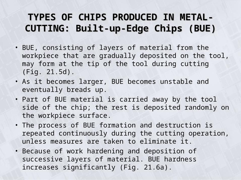
• BUE, consisting of layers of material from the workpiece that are gradually deposited on the tool, may form at the tip of the tool during cutting (Fig. 21.5d).
• As it becomes larger, BUE becomes unstable and eventually breads up.
• Part of BUE material is carried away by the tool side of the chip; the rest is deposited randomly on the workpiece surface.
• The process of BUE formation and destruction is repeated continuously during the cutting operation, unless measures are taken to eliminate it.
• Because of work hardening and deposition of successive layers of material. BUE hardness increases significantly (Fig. 21.6a).
TYPES OF CHIPS PRODUCED IN METAL-TYPES OF CHIPS PRODUCED IN METAL-CUTTING: Built-up-Edge Chips (BUE)CUTTING: Built-up-Edge Chips (BUE)
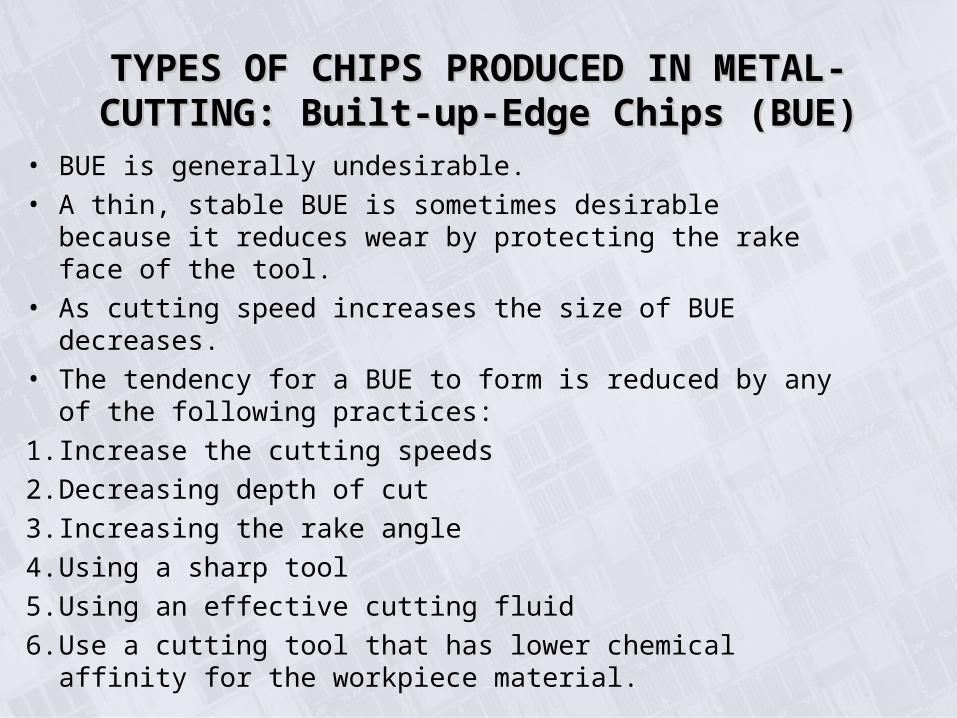
• BUE is generally undesirable.
• A thin, stable BUE is sometimes desirable because it reduces wear by protecting the rake face of the tool.
• As cutting speed increases the size of BUE decreases.
• The tendency for a BUE to form is reduced by any of the following practices:
1. Increase the cutting speeds
2. Decreasing depth of cut
3. Increasing the rake angle
4. Using a sharp tool
5. Using an effective cutting fluid
6. Use a cutting tool that has lower chemical affinity for the workpiece material.
Built-up EdgeBuilt-up Edge
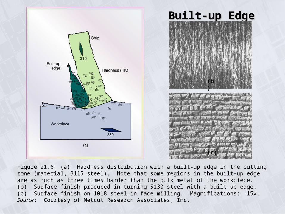
Figure 21.6 (a) Hardness distribution with a built-up edge in the cutting zone (material, 3115 steel). Note that some regions in the built-up edge are as much as three times harder than the bulk metal of the workpiece. (b) Surface finish produced in turning 5130 steel with a built-up edge. (c) Surface finish on 1018 steel in face milling. Magnifications: 15x. Source: Courtesy of Metcut Research Associates, Inc.
(b)
(c)
TYPES OF CHIPS PRODUCED IN METAL-TYPES OF CHIPS PRODUCED IN METAL-CUTTING: Serrated ChipsCUTTING: Serrated Chips
• Serrated chips: semi-continuous chips with zones of low and high shear strain (Fig. 21.5e).
• Metals with low thermal conductivity and strength that decreases sharply with temperature, such as titanium, exhibit this behavior.
• The chips have a saw-tooth-like appearance.
TYPES OF CHIPS PRODUCED IN METAL-TYPES OF CHIPS PRODUCED IN METAL-CUTTING: Discontinuous Chips (DCs)CUTTING: Discontinuous Chips (DCs)
• DCs consist of segments that may be firmly or loosely attached to each other (Fig. 21.5f ).
• DCs usually form under the following conditions:
1. Brittle workpiece materials
2. Workpiece materials that contain hard inclusions and impurities, or have structures such as the graphite flakes in gray cast iron.
3. Very low or very high cutting speeds.
4. Large depths of cut.
5. Low rake angles.
6. Lack of an effective cutting fluid.
7. Low stiffness of the machine tool.
• Because of the discontinuous nature of chip formation, forces continually vary during cutting.
• Hence, the stiffness or rigidity of the cutting-tool holder, the Workholding devices, and the machine tool are important in cutting with both DC and serrated-chip formation
TYPES OF CHIPS PRODUCED IN METAL-TYPES OF CHIPS PRODUCED IN METAL-CUTTING: Discontinuous Chips (DCs)CUTTING: Discontinuous Chips (DCs)
Chip BreakerChip Breaker
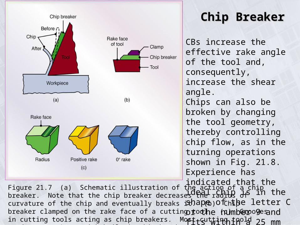
Figure 21.7 (a) Schematic illustration of the action of a chip breaker. Note that the chip breaker decreases the radius of curvature of the chip and eventually breaks it. (b) Chip breaker clamped on the rake face of a cutting tool. (c) Grooves in cutting tools acting as chip breakers. Most cutting toold used now are inserts with built-in chip breaker features.
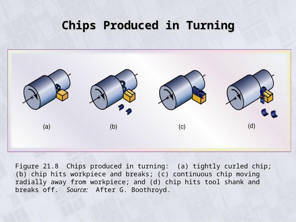
CBs increase the effective rake angle of the tool and, consequently, increase the shear angle.Chips can also be broken by changing the tool geometry, thereby controlling chip flow, as in the turning operations shown in Fig. 21.8.Experience has indicated that the ideal chip is in the shape of the letter C or the number 9 and fits within a 25 mm square block.
Chips Produced in TurningChips Produced in Turning
Figure 21.8 Chips produced in turning: (a) tightly curled chip; (b) chip hits workpiece and breaks; (c) continuous chip moving radially away from workpiece; and (d) chip hits tool shank and breaks off. Source: After G. Boothroyd.

TYPES OF CHIPS PRODUCED IN METAL-TYPES OF CHIPS PRODUCED IN METAL-CUTTING: Chips Breakers (CBs)CUTTING: Chips Breakers (CBs)
• With soft workpiece materials such as pure aluminum or copper, chip breaking by such means is generally not effective.
• Common techniques used with such materials, include machining at small increments and then pausing (so that a chip is not generated) or reversing the feed by small increments.
• In interrupted cutting operations, such as milling, chip breakers are generally not necessary, since the chips already have finite lengths because of the intermittent nature of the operation.

THE MECHANICS OF OBLIQUE CUTTINGTHE MECHANICS OF OBLIQUE CUTTING
• Chip in Fig. 21.9a f lows up the rake face of the tool at angle αc (chip flow angle), which is measured in the plane of the tool face.
• Angle αn , the normal rake angle, is a basic geometric property of the tool. This is the angle between the normal oz to the workpiece surface and the line oa on the tool face.
• The workpiece material approaches the tool at a velocity V and leaves the surface (as a chip) with a velocity V
Figure 21.9 (a) Schematic illustration of cutting with an oblique tool. Note the direction of chip movement. (b) Top view, showing the inclination angle, i,. (c) Types of chips produced with tools at increasing inclination angles.
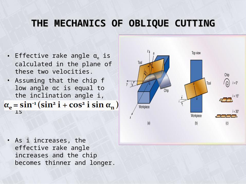
• Effective rake angle αe is calculated in the plane of these two velocities.
• Assuming that the chip f low angle αc is equal to the inclination angle i, the effective rake angle αe is
• As i increases, the effective rake angle increases and the chip becomes thinner and longer.
THE MECHANICS OF OBLIQUE CUTTINGTHE MECHANICS OF OBLIQUE CUTTING
Right-hand Cutting Tool and InsertRight-hand Cutting Tool and Insert
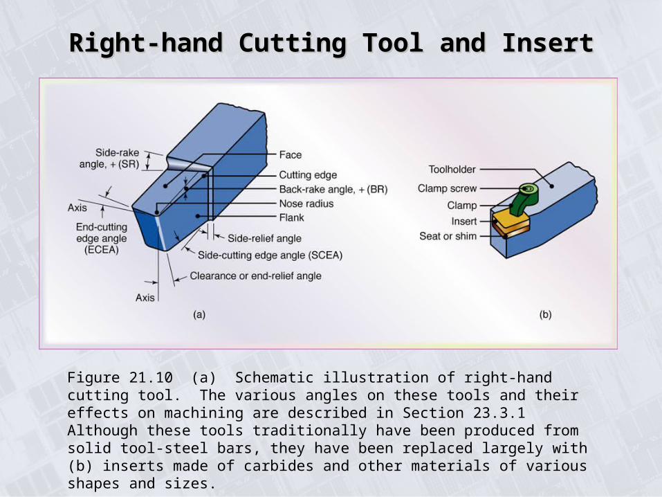
Figure 21.10 (a) Schematic illustration of right-hand cutting tool. The various angles on these tools and their effects on machining are described in Section 23.3.1 Although these tools traditionally have been produced from solid tool-steel bars, they have been replaced largely with (b) inserts made of carbides and other materials of various shapes and sizes.
• Knowledge of the cutting forces and power involved in machining operations is important for the following reasons:
a. Machine tools can be properly designed to minimize distortion of the machine components, maintain the desired dimensional accuracy of the machined part, and help select appropriate tool holders and work-holding devices.
b. The workpiece is capable of withstanding these forces without excessive distortion.
c. Power requirements must be known in order to enable the selection of a machine tool with adequate electric power.
CUTTING FORCES AND POWERCUTTING FORCES AND POWER
CUTTING FORCES AND POWERCUTTING FORCES AND POWER
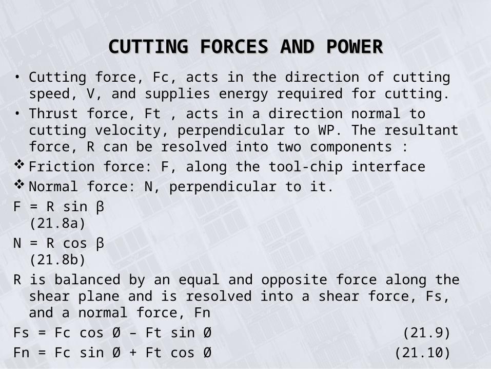
• Cutting force, Fc, acts in the direction of cutting speed, V, and supplies energy required for cutting.
• Thrust force, Ft , acts in a direction normal to cutting velocity, perpendicular to WP. The resultant force, R can be resolved into two components :
Friction force: F, along the tool-chip interface Normal force: N, perpendicular to it.
F = R sin β (21.8a)
N = R cos β (21.8b)
R is balanced by an equal and opposite force along the shear plane and is resolved into a shear force, Fs, and a normal force, Fn
Fs = Fc cos Ø – Ft sin Ø (21.9)
Fn = Fc sin Ø + Ft cos Ø (21.10)
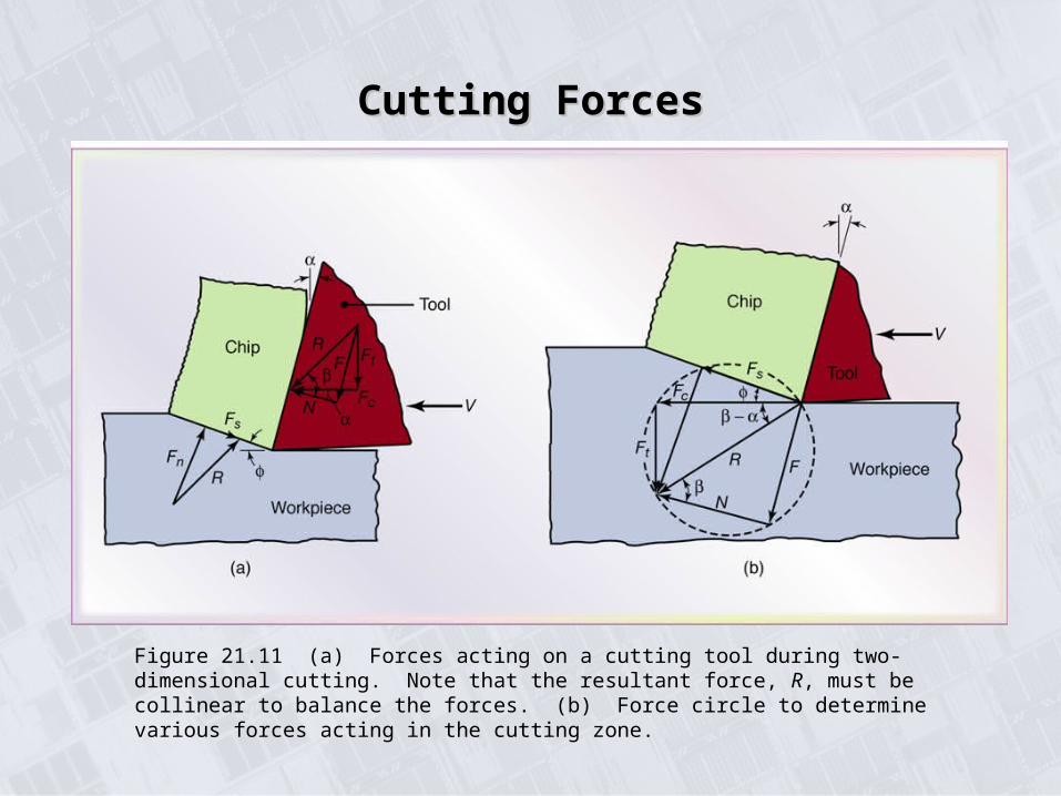
Cutting ForcesCutting Forces
Figure 21.11 (a) Forces acting on a cutting tool during two-dimensional cutting. Note that the resultant force, R, must be collinear to balance the forces. (b) Force circle to determine various forces acting in the cutting zone.
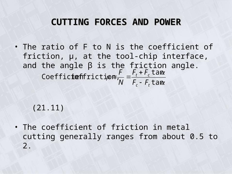
• The ratio of F to N is the coefficient of friction, μ, at the tool-chip interface, and the angle β is the friction angle.
(21.11)
• The coefficient of friction in metal cutting generally ranges from about 0.5 to 2.
tan
tan friction, oft Coefficien
tc
ct
FF
FF
N
F
CUTTING FORCES AND POWERCUTTING FORCES AND POWER
CUTTING FORCES AND POWERCUTTING FORCES AND POWERThrust ForceThrust Force
• If the thrust force is too high or if the machine tool is not sufficiently stiff, the tool will be pushed away from the surface being machined.
• This movement will, in turn, reduce the depth of cut, resulting in lack of dimensional accuracy in the machined part, As the rake angle increases and/or friction at the rake face decreases, this force can act upward.
• This situation can be visualized by noting that when μ = 0 (that is, β = 0), the resultant force, R, coincides with the normal force, N.
• In this case, R will have a thrust-force component that is upward.

CUTTING FORCES AND POWER - CUTTING FORCES AND POWER - PowerPower
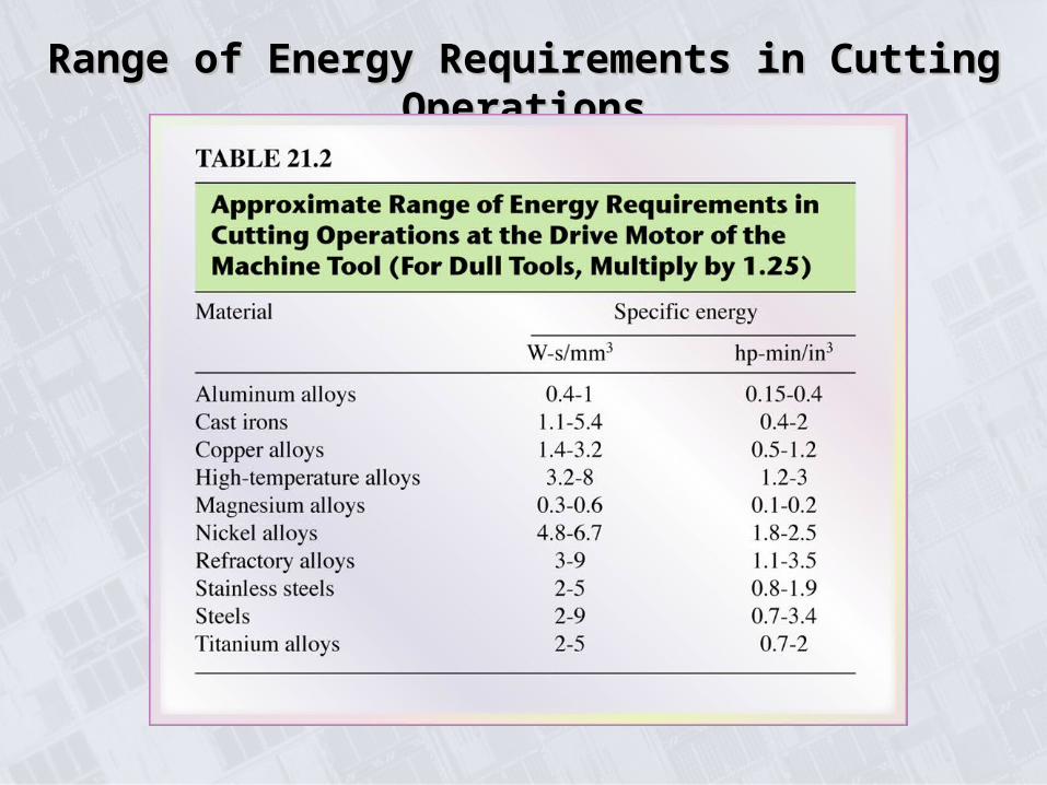
Range of Energy Requirements in Cutting OperationsRange of Energy Requirements in Cutting Operations

• EXAMPLE 21.l Relative Energies in Cutting
In an orthogonal cutting operation, to = 0.13 mm, V = 120 m/min, α = 10° and the width of cut = 6 mm. It is observed that tc = 0.23 mm, Fc = 500 N and Ft = 200 N. Calculate the percentage of the total energy that goes into overcoming friction at the tool-chip interface.
Solution The percentage of the energy can be expressed as:
CUTTING FORCES AND POWER CUTTING FORCES AND POWER
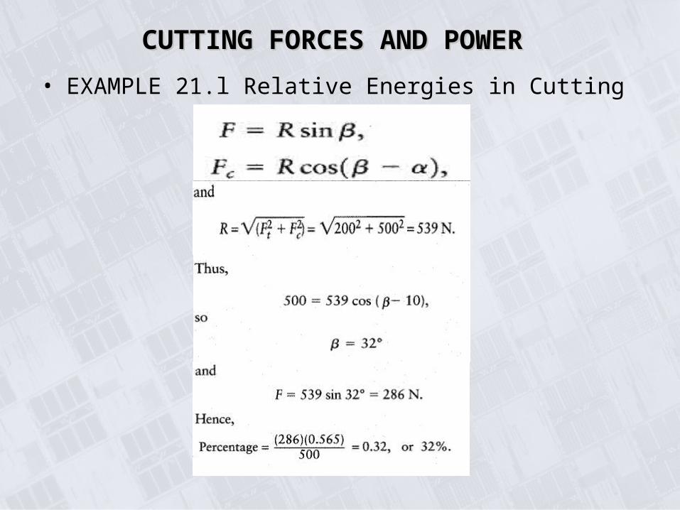
• EXAMPLE 21.l Relative Energies in Cutting
CUTTING FORCES AND POWER CUTTING FORCES AND POWER
TEMPERATURE IN CUTTINGTEMPERATURE IN CUTTING
• The main sources of heat generation are the primary shear zone and the tool-chip interface.
• If the tool is dull or worn, heat is also generated when the tool tip rubs against the machined surface.
• Cutting temperatures increase with:
1. strength of the workpiece material
2. cutting speed
3. depth of cut
• Cutting temperatures decrease with increasing specific heat and thermal conductivity of workpiece material.
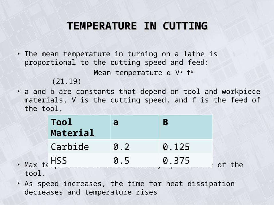
• The mean temperature in turning on a lathe is proportional to the cutting speed and feed:
Mean temperature α Va fb (21.19)
• a and b are constants that depend on tool and workpiece materials, V is the cutting speed, and f is the feed of the tool.
• Max temperature is about halfway up the face of the tool.
• As speed increases, the time for heat dissipation decreases and temperature rises
Tool Material a B
Carbide 0.2 0.125
HSS 0.5 0.375
TEMPERATURE IN CUTTINGTEMPERATURE IN CUTTING
Temperatures in Cutting ZoneTemperatures in Cutting Zone
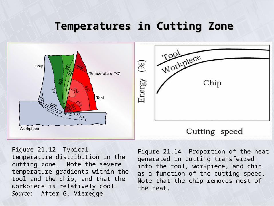
Figure 21.12 Typical temperature distribution in the cutting zone. Note the severe temperature gradients within the tool and the chip, and that the workpiece is relatively cool. Source: After G. Vieregge.
Figure 21.14 Proportion of the heat generated in cutting transferred into the tool, workpiece, and chip as a function of the cutting speed. Note that the chip removes most of the heat.
Temperatures Developed in Turning 52100 SteelTemperatures Developed in Turning 52100 Steel
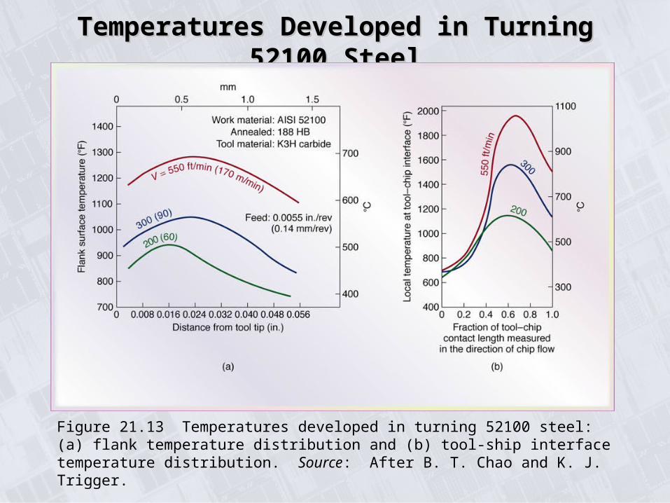
Figure 21.13 Temperatures developed in turning 52100 steel: (a) flank temperature distribution and (b) tool-ship interface temperature distribution. Source: After B. T. Chao and K. J. Trigger.
TOOL LIFE: WEAR AND FAILURETOOL LIFE: WEAR AND FAILURE
• Conditions that would cause tool wear:
1. High localized stresses
2. High temp
3. Sliding of chip along the rack face
4. Sliding of the tool along the machined surface
• The rate of wear depends on:
1. Tool and workpiece materials
2. Tool shape
3. Cutting fluids
4. Process parameters
5. Machine tool char
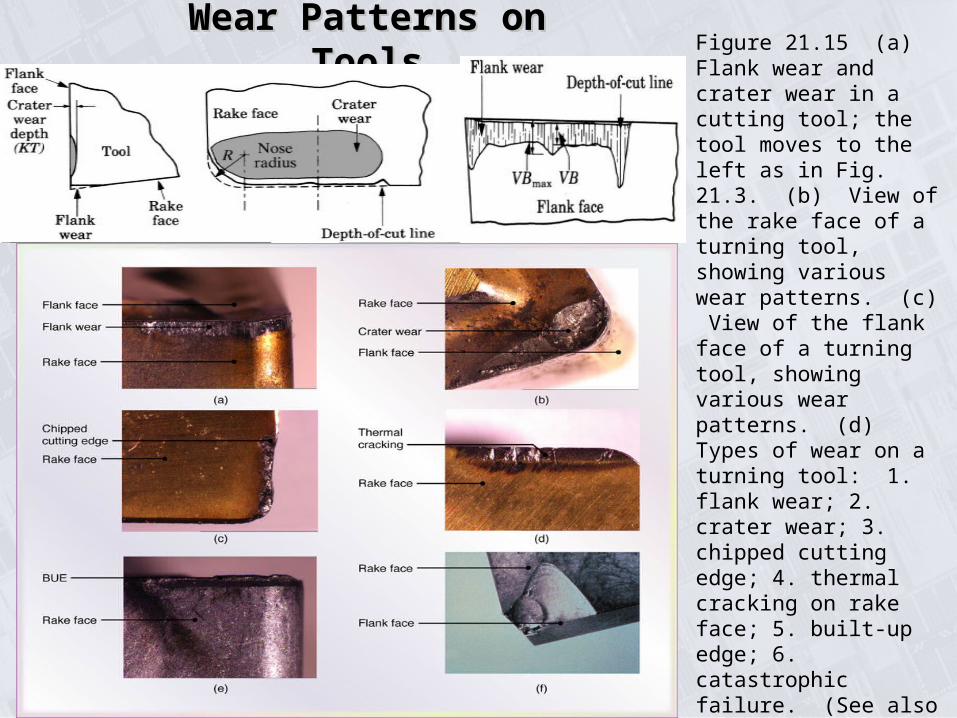
Wear Patterns on ToolsWear Patterns on Tools Figure 21.15 (a) Flank wear and crater wear in a cutting tool; the tool moves to the left as in Fig. 21.3. (b) View of the rake face of a turning tool, showing various wear patterns. (c) View of the flank face of a turning tool, showing various wear patterns. (d) Types of wear on a turning tool: 1. flank wear; 2. crater wear; 3. chipped cutting edge; 4. thermal cracking on rake face; 5. built-up edge; 6. catastrophic failure. (See also Fig. 21.18.) Source: Courtesy of Kennametal, Inc.
TOOL LIFE: WEAR AND FAILURETOOL LIFE: WEAR AND FAILURE
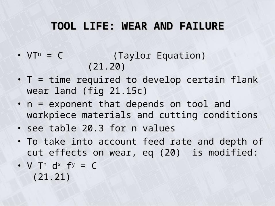
• VTn = C (Taylor Equation) (21.20)
• T = time required to develop certain flank wear land (fig 21.15c)
• n = exponent that depends on tool and workpiece materials and cutting conditions
• see table 20.3 for n values
• To take into account feed rate and depth of cut effects on wear, eq (20) is modified:
• V Tn dx fy = C (21.21)
Taylor Tool Life EquationTaylor Tool Life Equation
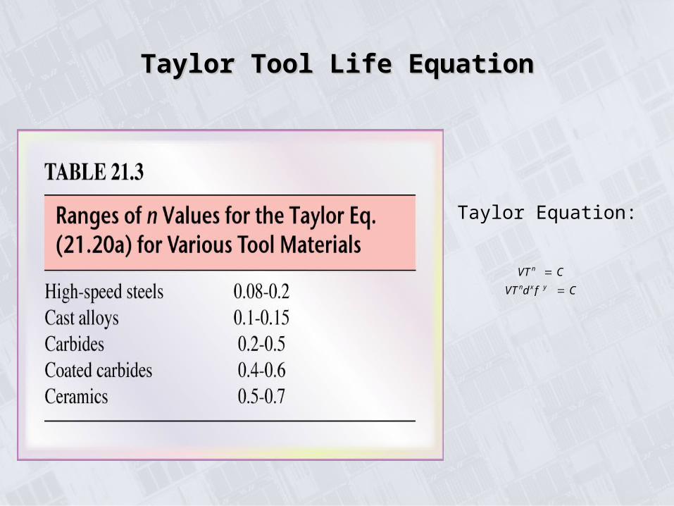
VTn C
VTndxf y C
Taylor Equation:
Manufacturing, Engineering & Technology, Fifth Edition, by Serope Kalpakjian and Steven R. Schmid.ISBN 0-13-148965-8. © 2006 Pearson Education, Inc., Upper Saddle River, NJ. All rights reserved.
Effect of Workpiece Hardness and Microstructure Effect of Workpiece Hardness and Microstructure on Tool Lifeon Tool Life
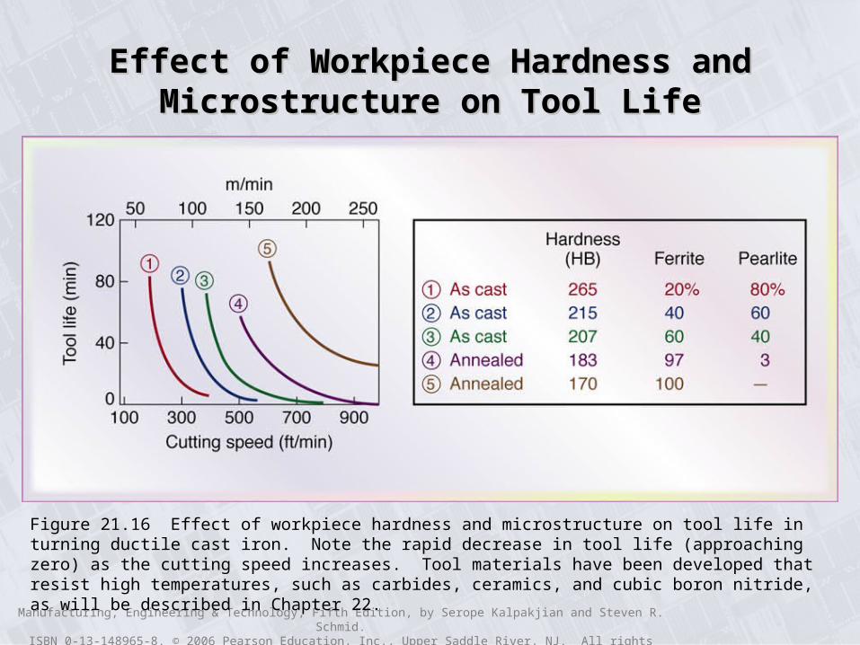
Figure 21.16 Effect of workpiece hardness and microstructure on tool life in turning ductile cast iron. Note the rapid decrease in tool life (approaching zero) as the cutting speed increases. Tool materials have been developed that resist high temperatures, such as carbides, ceramics, and cubic boron nitride, as will be described in Chapter 22.
Manufacturing, Engineering & Technology, Fifth Edition, by Serope Kalpakjian and Steven R. Schmid.ISBN 0-13-148965-8. © 2006 Pearson Education, Inc., Upper Saddle River, NJ. All rights reserved.
Tool-life CurvesTool-life Curves
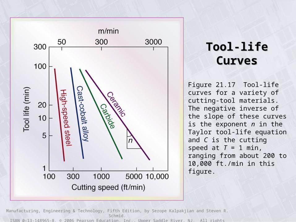
Figure 21.17 Tool-life curves for a variety of cutting-tool materials. The negative inverse of the slope of these curves is the exponent n in the Taylor tool-life equation and C is the cutting speed at T = 1 min, ranging from about 200 to 10,000 ft./min in this figure.
TOOL LIFE: WEAR AND FAILURETOOL LIFE: WEAR AND FAILUREAllowable Wear LandAllowable Wear Land
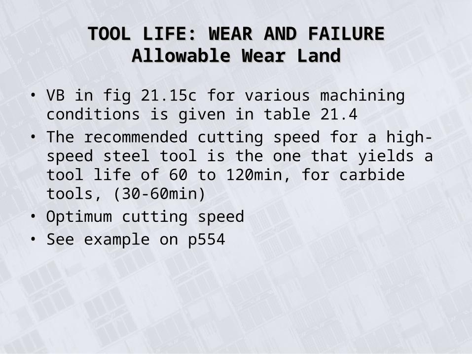
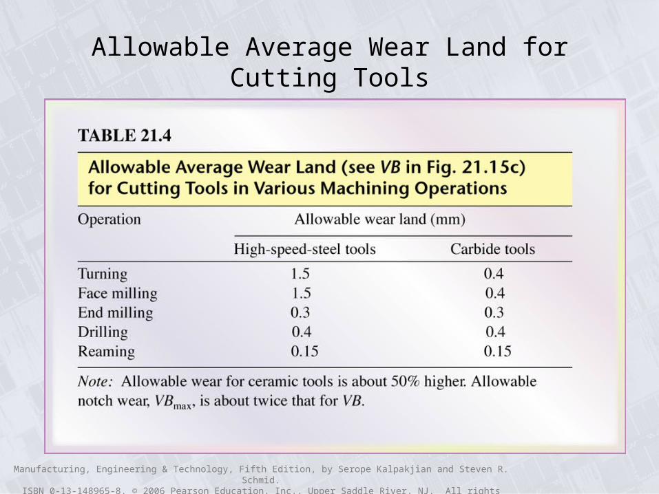
• VB in fig 21.15c for various machining conditions is given in table 21.4
• The recommended cutting speed for a high-speed steel tool is the one that yields a tool life of 60 to 120min, for carbide tools, (30-60min)
• Optimum cutting speed
• See example on p554
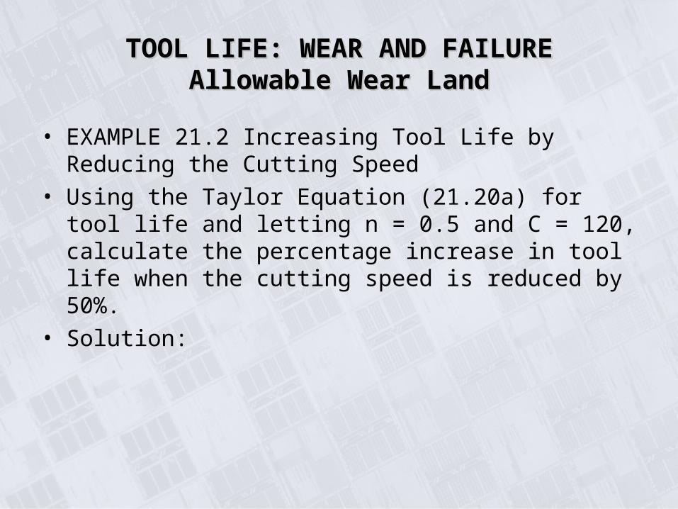
• EXAMPLE 21.2 Increasing Tool Life by Reducing the Cutting Speed
• Using the Taylor Equation (21.20a) for tool life and letting n = 0.5 and C = 120, calculate the percentage increase in tool life when the cutting speed is reduced by 50%.
• Solution:
TOOL LIFE: WEAR AND FAILURETOOL LIFE: WEAR AND FAILUREAllowable Wear LandAllowable Wear Land
Manufacturing, Engineering & Technology, Fifth Edition, by Serope Kalpakjian and Steven R. Schmid.ISBN 0-13-148965-8. © 2006 Pearson Education, Inc., Upper Saddle River, NJ. All rights reserved.
Allowable Average Wear Land for Cutting Tools
Manufacturing, Engineering & Technology, Fifth Edition, by Serope Kalpakjian and Steven R. Schmid.ISBN 0-13-148965-8. © 2006 Pearson Education, Inc., Upper Saddle River, NJ. All rights reserved.
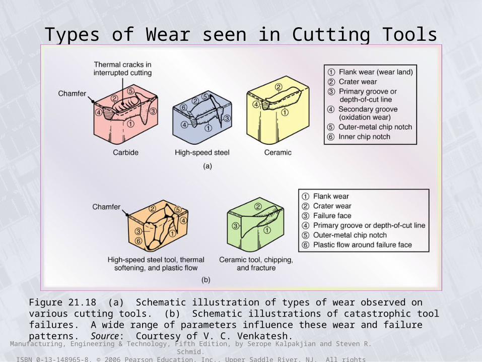
Types of Wear seen in Cutting Tools
Figure 21.18 (a) Schematic illustration of types of wear observed on various cutting tools. (b) Schematic illustrations of catastrophic tool failures. A wide range of parameters influence these wear and failure patterns. Source: Courtesy of V. C. Venkatesh.

Manufacturing, Engineering & Technology, Fifth Edition, by Serope Kalpakjian and Steven R. Schmid.ISBN 0-13-148965-8. © 2006 Pearson Education, Inc., Upper Saddle River, NJ. All rights reserved.
Relationship between Crater-Wear Rate and Average Tool-Chip Interface Temperature
Figure 21.19 Relationship between crater-wear rate and average tool-chip interface temperature: 1) High-speed steel, 2) C-1 carbide, and 3) C-5 carbide (see Table 22.4). Note how rapidly crater-wear rate increases with an incremental increase in temperature. Source: After B. T Chao and K. J Trigger.
Manufacturing, Engineering & Technology, Fifth Edition, by Serope Kalpakjian and Steven R. Schmid.ISBN 0-13-148965-8. © 2006 Pearson Education, Inc., Upper Saddle River, NJ. All rights reserved.
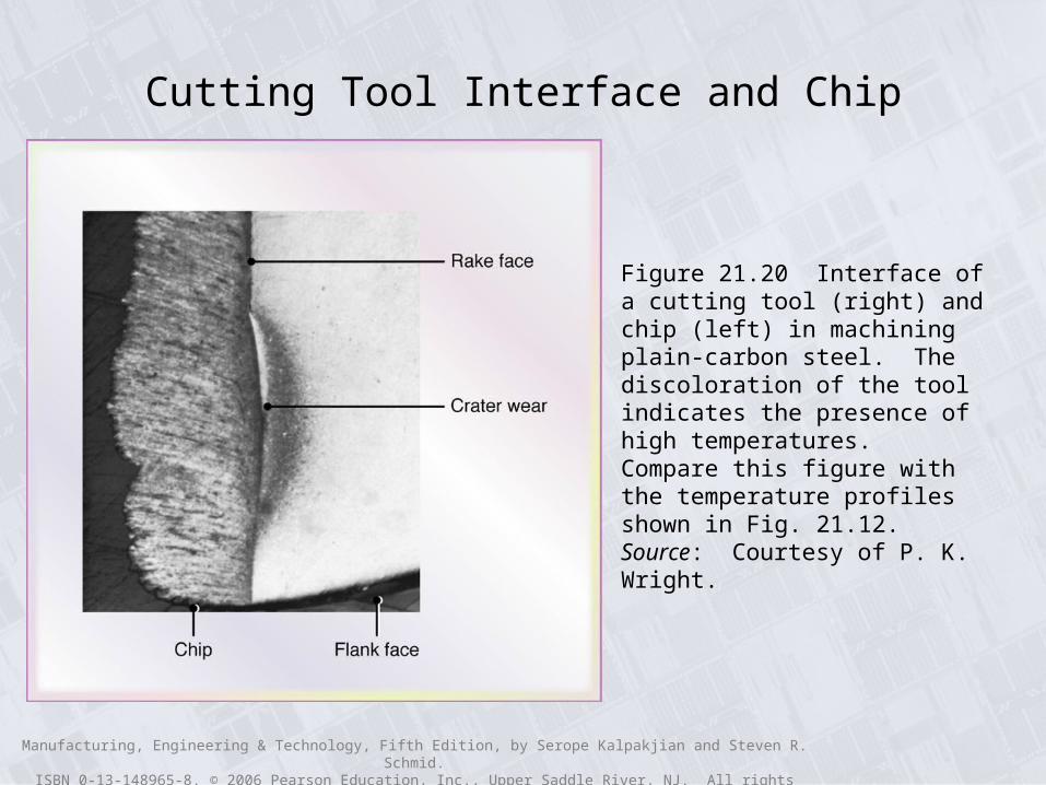
Cutting Tool Interface and Chip
Figure 21.20 Interface of a cutting tool (right) and chip (left) in machining plain-carbon steel. The discoloration of the tool indicates the presence of high temperatures. Compare this figure with the temperature profiles shown in Fig. 21.12. Source: Courtesy of P. K. Wright.
Manufacturing, Engineering & Technology, Fifth Edition, by Serope Kalpakjian and Steven R. Schmid.ISBN 0-13-148965-8. © 2006 Pearson Education, Inc., Upper Saddle River, NJ. All rights reserved.
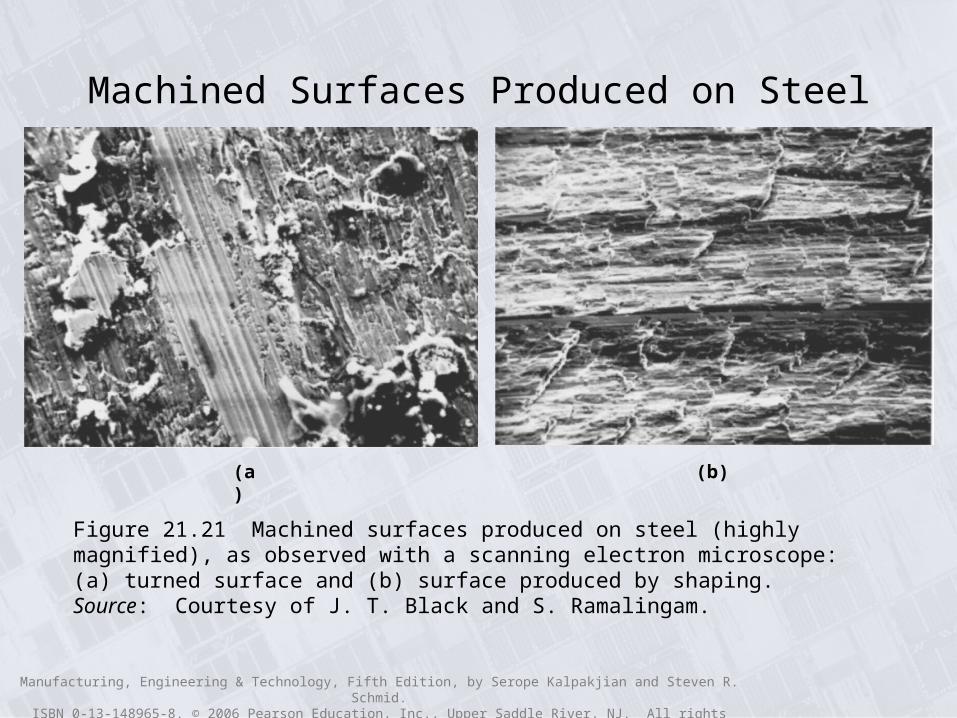
Machined Surfaces Produced on Steel
(a) (b)
Figure 21.21 Machined surfaces produced on steel (highly magnified), as observed with a scanning electron microscope: (a) turned surface and (b) surface produced by shaping. Source: Courtesy of J. T. Black and S. Ramalingam.
Manufacturing, Engineering & Technology, Fifth Edition, by Serope Kalpakjian and Steven R. Schmid.ISBN 0-13-148965-8. © 2006 Pearson Education, Inc., Upper Saddle River, NJ. All rights reserved.
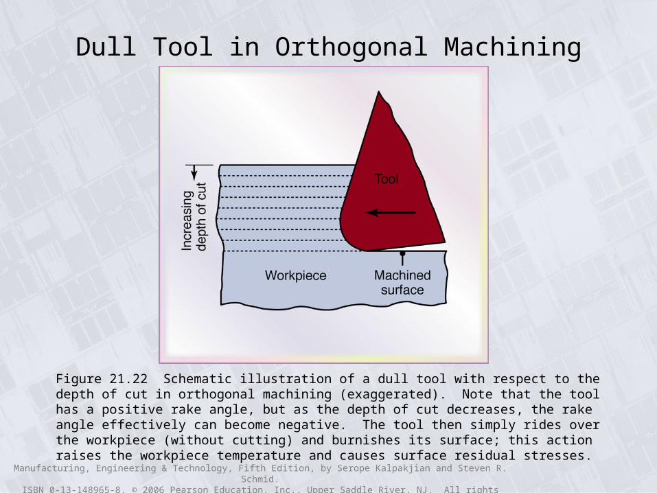
Dull Tool in Orthogonal Machining
Figure 21.22 Schematic illustration of a dull tool with respect to the depth of cut in orthogonal machining (exaggerated). Note that the tool has a positive rake angle, but as the depth of cut decreases, the rake angle effectively can become negative. The tool then simply rides over the workpiece (without cutting) and burnishes its surface; this action raises the workpiece temperature and causes surface residual stresses.
Manufacturing, Engineering & Technology, Fifth Edition, by Serope Kalpakjian and Steven R. Schmid.ISBN 0-13-148965-8. © 2006 Pearson Education, Inc., Upper Saddle River, NJ. All rights reserved.
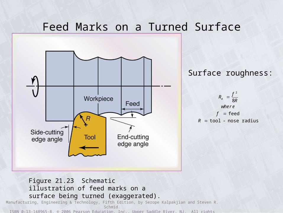
Feed Marks on a Turned Surface
Figure 21.23 Schematic illustration of feed marks on a surface being turned (exaggerated).
Ra f 2
8Rwhere
f feed
R tool - nose radius
Surface roughness: