Embed Size (px)
Citation preview
Computer Systems Design and Architecture 2nd Edition © 2004 Prentice Hall, Mark Franklin S06
Chapter 2 Topics2.1 Classification of Computers & Instructions2.2 Classes of Instruction Sets2.3 Informal Description of Simple RISC Computer, SRC
See Appendix C for Assembly language information.
2.4 Formal SRC Description: Use Register Transfer Notation (RTN)
2.5 RTN Description of Addressing Modes2.6 Register Transfers & Logic Circuits:
Behavior Hardware
Computer Systems Design and Architecture 2nd Edition © 2004 Prentice Hall, Mark Franklin S06
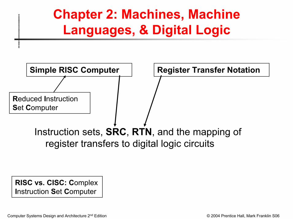
Chapter 2: Machines, Machine Languages, & Digital Logic
Instruction sets, SRC, RTN, and the mapping of register transfers to digital logic circuits
Simple RISC Computer
Reduced InstructionSet Computer
Register Transfer Notation
RISC vs. CISC: ComplexInstruction Set Computer
Computer Systems Design and Architecture 2nd Edition © 2004 Prentice Hall, Mark Franklin S06
What are the components of an ISA?Sometimes known as The Programmers Model of the machineStorage cells
General and special purpose registers in the CPUMany general purpose cells of same size in memoryStorage associated with I/O devices
The Machine Instruction SetThe instruction set is the entire repertoire of machine operationsMakes use of storage cells, formats, and results of the fetch/execute cycle
The Instruction FormatSize and meaning of fields within the instruction
The nature of the Fetch/Execute cycleThings that are done before the operation code, OPCODE, is known

Computer Systems Design and Architecture 2nd Edition © 2004 Prentice Hall, Mark Franklin S06
What Must an Instruction Specify?
Which operation to perform: add r0, r1, r3Ans: Op code: add, load, branch, etc.
Where to find the operand or operands add r0, r1, r3 In CPU registers, memory cells, I/O locations, or part of instruction
Where to store result add r0, r1, r3In CPU register or memory cell
Next instruction location add r0, r1, r3 br endloop
The default is the memory address pointed to by program counter—PC:(i.e., the next instruction in sequence).
Sometimes there is no operand, or no result, or no next instruction. Examples?
Computer Systems Design and Architecture 2nd Edition © 2004 Prentice Hall, Mark Franklin S06
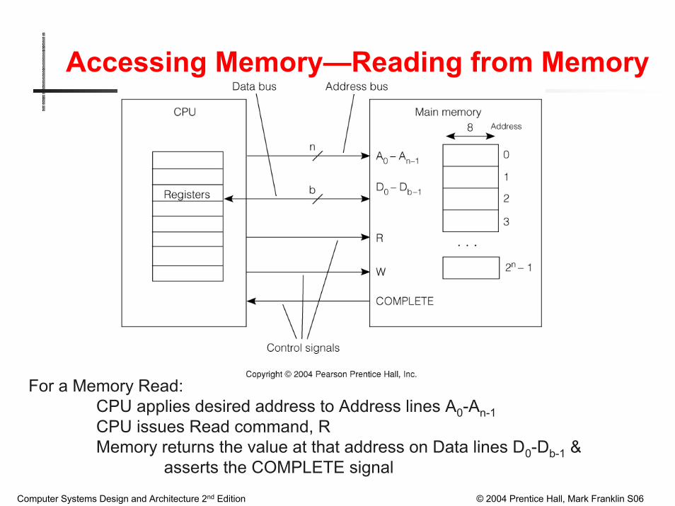
Accessing Memory—Reading from Memory
For a Memory Read:CPU applies desired address to Address lines A0-An-1CPU issues Read command, RMemory returns the value at that address on Data lines D0-Db-1 &
asserts the COMPLETE signal
Computer Systems Design and Architecture 2nd Edition © 2004 Prentice Hall, Mark Franklin S06
Classes of Instructions
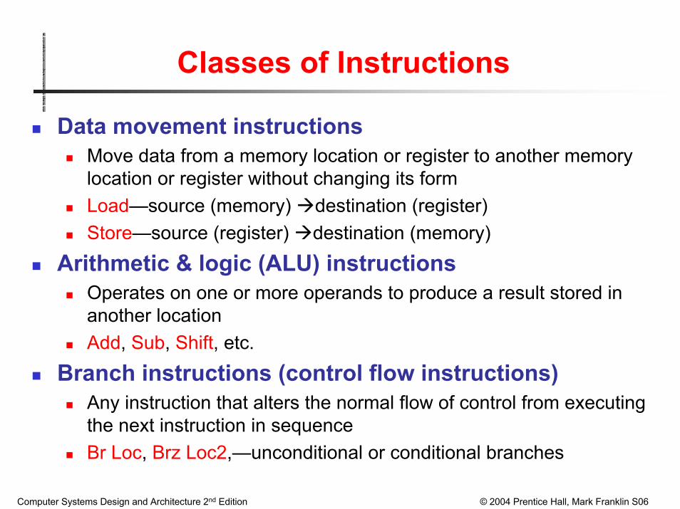
Data movement instructionsMove data from a memory location or register to another memory location or register without changing its formLoad—source (memory) destination (register)Store—source (register) destination (memory)
Arithmetic & logic (ALU) instructionsOperates on one or more operands to produce a result stored in another locationAdd, Sub, Shift, etc.
Branch instructions (control flow instructions)Any instruction that alters the normal flow of control from executing the next instruction in sequenceBr Loc, Brz Loc2,—unconditional or conditional branches
Computer Systems Design and Architecture 2nd Edition © 2004 Prentice Hall, Mark Franklin S06
Examples: Data Movement Instructions
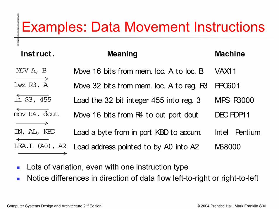
MOV A, B Move 16 bits from mem. loc. A to loc. B VAX11
Inst ruct . Meaning Machine
lwz R3, A Move 32 bits from mem. loc. A to reg. R3 PPC601
li $3, 455 Load the 32 bit integer 455 into reg. 3 MIPS R3000
mov R4, dout Move 16 bits from R4 to out port dout DEC PDP11
IN, AL, KBD Load a byte from in port KBD to accum. Intel Pentium
LEA.L (A0), A2 Load address pointed to by A0 into A2 M68000
Lots of variation, even with one instruction typeNotice differences in direction of data flow left-to-right or right-to-left
Computer Systems Design and Architecture 2nd Edition © 2004 Prentice Hall, Mark Franklin S06
Examples: ALU(Arithmetic, Logic) Instructions
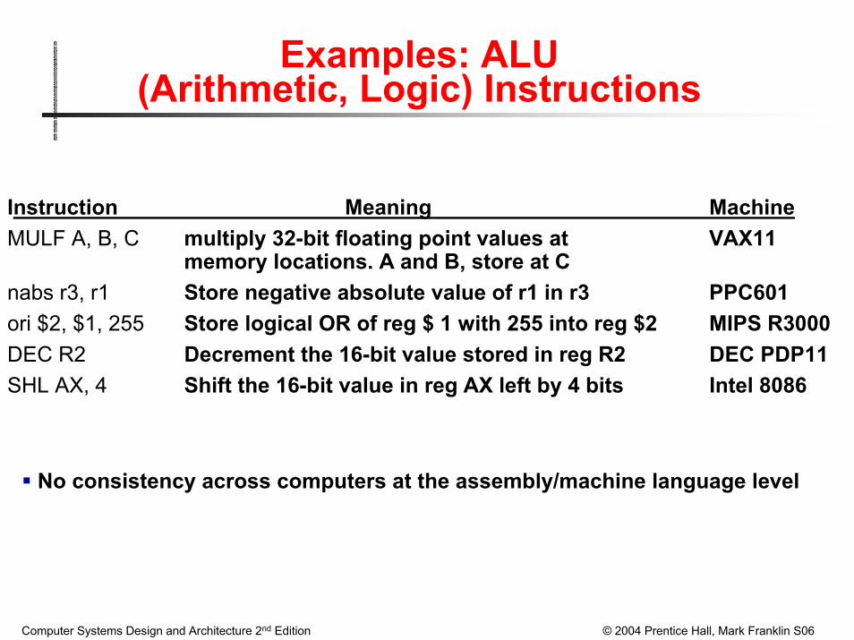
Instruction Meaning MachineMULF A, B, C multiply 32-bit floating point values at VAX11
memory locations. A and B, store at Cnabs r3, r1 Store negative absolute value of r1 in r3 PPC601ori $2, $1, 255 Store logical OR of reg $ 1 with 255 into reg $2 MIPS R3000DEC R2 Decrement the 16-bit value stored in reg R2 DEC PDP11SHL AX, 4 Shift the 16-bit value in reg AX left by 4 bits Intel 8086
No consistency across computers at the assembly/machine language level

Computer Systems Design and Architecture 2nd Edition © 2004 Prentice Hall, Mark Franklin S06
Branch Instruction Examples
Instruction Meaning MachineBLSS A, Tgt Branch to address Tgt if the least significant VAX11
bit of memory location A is set (i.e., = 1)bun r2 Branch to location in R2 if result of previous PPC601
floating point computation was Not a Number (NAN)beq $2, $1, 32 Branch to location (PC + 4 + 32) if contents MIPS R3000
of $1 and $2 are equalSOB R4, Loop Decrement R4 and branch to Loop if R4 ≠ 0 DEC PDP11JCXZ Addr Jump to Addr if contents of register CX = 0. Intel 8086
Computer Systems Design and Architecture 2nd Edition © 2004 Prentice Hall, Mark Franklin S06
CPU Registers Associated with Flow of Control—Branch Instructions
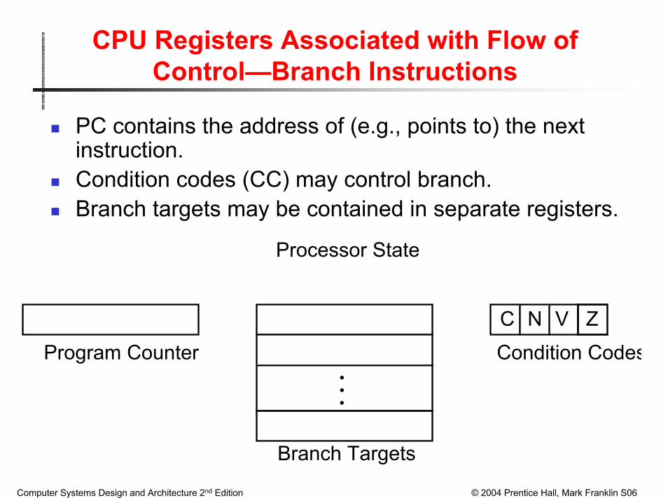
PC contains the address of (e.g., points to) the next instruction.Condition codes (CC) may control branch.Branch targets may be contained in separate registers.
Processor State
C N V Z
Program Counter
Branch Targets
Condition Codes•••
Computer Systems Design and Architecture 2nd Edition © 2004 Prentice Hall, Mark Franklin S06
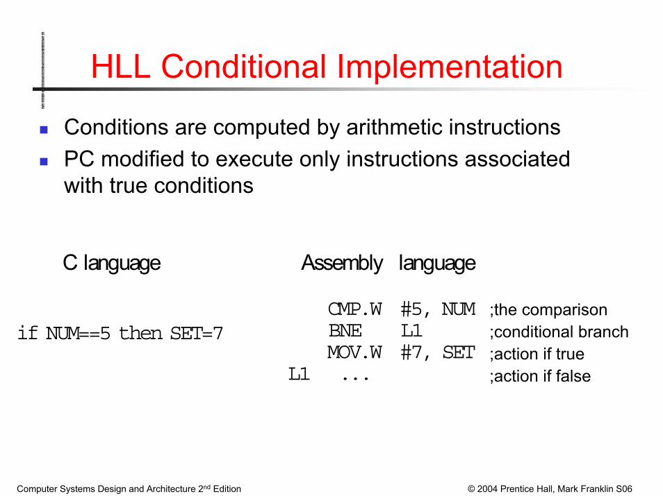
HLL Conditional Implementation
Conditions are computed by arithmetic instructionsPC modified to execute only instructions associated with true conditions
C language Assembly language
if NUM==5 then SET=7 CMP.W #5, NUM BNE L1 MOV.W #7, SETL1 ...
;the comparison;conditional branch;action if true;action if false

Computer Systems Design and Architecture 2nd Edition © 2004 Prentice Hall, Mark Franklin S06
Most General Instruction
• Operation or Operations to be performed
• Number of operands
• Location of operands
• Number of results
• Location of results
• Next instruction location
• Next instruction location dependent on condition(s)

Computer Systems Design and Architecture 2nd Edition © 2004 Prentice Hall, Mark Franklin S06
CPU Registers may have a “personality”
Architecture classes are often based on where the operands & results are located & how they are specified by the instruction.They can be in CPU registers or main memory
TopSecond
Stack ArithmeticRegisters
AddressRegisters
General PurposeRegisters
Push Pop
•••
•••
••••
••
Stack Machine Accumulator Machine General RegisterMachine

Computer Systems Design and Architecture 2nd Edition © 2004 Prentice Hall, Mark Franklin S06
MOST GENERAL INSTRUCTION
What is a possible format for the most general instruction type?
Computer Systems Design and Architecture 2nd Edition © 2004 Prentice Hall, Mark Franklin S06
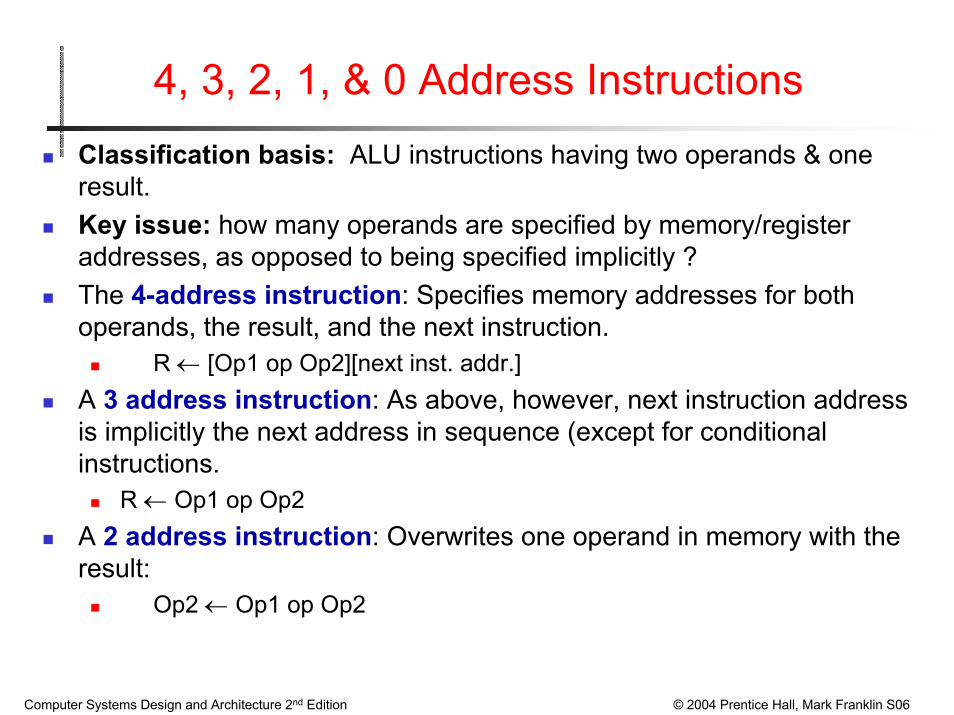
4, 3, 2, 1, & 0 Address InstructionsClassification basis: ALU instructions having two operands & one result. Key issue: how many operands are specified by memory/register addresses, as opposed to being specified implicitly ?The 4-address instruction: Specifies memory addresses for both operands, the result, and the next instruction.
R ← [Op1 op Op2][next inst. addr.]A 3 address instruction: As above, however, next instruction address is implicitly the next address in sequence (except for conditional instructions.
R ← Op1 op Op2A 2 address instruction: Overwrites one operand in memory with the result:
Op2 ← Op1 op Op2

Computer Systems Design and Architecture 2nd Edition © 2004 Prentice Hall, Mark Franklin S06
4, 3, 2, 1, & 0 Address InstructionsA 1 address instruction: A register, the accumulator (Acc), holds one operand & receives the result (no address needed):
Acc ← Acc op Op1
A 0 address, Stack Machine, uses a register stack to hold both operands & the result. TOS =Top Of Stack, SOS = Second On Stack :
TOS ← TOS op SOS
TOS
SOSStack

Computer Systems Design and Architecture 2nd Edition © 2004 Prentice Hall, Mark Franklin S06
The 4 Address Instruction
Explicit addresses for operands, result & next instructionExample assumes 24-bit addresses & 8-bit opcode(Instruction size = ?)

Computer Systems Design and Architecture 2nd Edition © 2004 Prentice Hall, Mark Franklin S06
The 3 Address Instruction
Address of next instruction kept in a processor state register—the PC (Except for explicit Branches/Jumps)Rest of addresses in instruction
Computer Systems Design and Architecture 2nd Edition © 2004 Prentice Hall, Mark Franklin S06
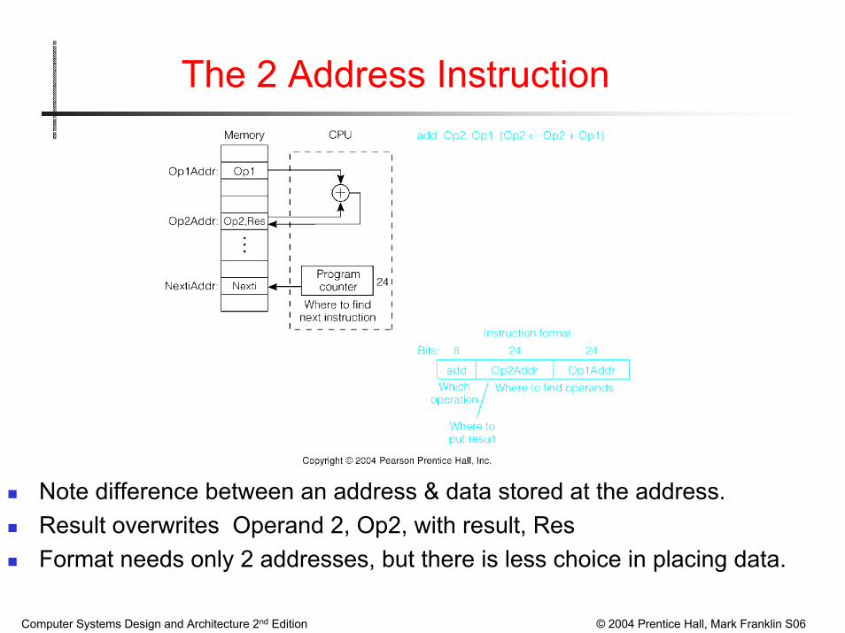
The 2 Address Instruction
Note difference between an address & data stored at the address.Result overwrites Operand 2, Op2, with result, ResFormat needs only 2 addresses, but there is less choice in placing data.

Computer Systems Design and Architecture 2nd Edition © 2004 Prentice Hall, Mark Franklin S06
Single Address Instructions
We now need instructions to load and store operands:LDA OpAddrSTA OpAddr
Special register, the accumulator, supplies 1 operand & stores resultOne memory address used for other operand

Computer Systems Design and Architecture 2nd Edition © 2004 Prentice Hall, Mark Franklin S06
The 0 Address Instruction
Uses a push down stack.Arithmetic uses stack for both operands. The result replaces them on the TOS.Must have a 1 address instructions to push & pop operands to & from the stack.
Computer Systems Design and Architecture 2nd Edition © 2004 Prentice Hall, Mark Franklin S06
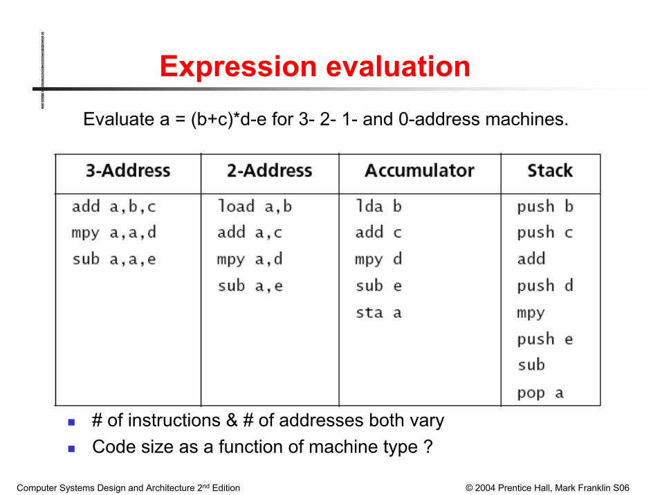
Expression evaluationEvaluate a = (b+c)*d-e for 3- 2- 1- and 0-address machines.
# of instructions & # of addresses both varyCode size as a function of machine type ?

Computer Systems Design and Architecture 2nd Edition © 2004 Prentice Hall, Mark Franklin S06
General Register Machines
The most common choice in today’s computersWhich register is specified by small “address” (3 to 6 bits for 8 to 64 registers)Load/store inst. have one long & one short (register) addr.: 1 1/2 addresses2-Operand arithmetic instruction has 3 short (register) addresses

Computer Systems Design and Architecture 2nd Edition © 2004 Prentice Hall, Mark Franklin S06
OPCODES: Variable vs Fixed Length
Fixed Length Opcodes: Say that we have a processor that has 8 opcodes. A fixed length encoding requires 3 bits. Average number of bits/opcode is 3.
ADD 000 BRE 100
LOAD 001 SUB 101
STORE 010 AND 110
BRA 011 OR 111

Computer Systems Design and Architecture 2nd Edition © 2004 Prentice Hall, Mark Franklin S06
OPCODES: Variable vs Fixed LengthVariable Length Opcodes: Say that the probability of using each of the opcodes is as follows:
ADD 1/4 BRE 1/16
LOAD 1/4 SUB 1/16
STORE 1/8 AND 1/16
BRA 1/8 OR 1/16
Consider the following encoding: ADD 00 BRE 1100
LOAD 01 SUB 1101
STORE 100 AND 1110
BRA 101 OR 1111
The average number of bits required for the opcode set is:
Avg. # Bits = (1/4)2 + (1/4)2 + (1/8)3 + (1/8)3 + (1/16)(4)4 = 2.75
NOTE: Reading opcode encoding (left to right) no opcode is a prefix of another opcode (“irreducible” property). Can use Huffman encoding.
Computer Systems Design and Architecture 2nd Edition © 2004 Prentice Hall, Mark Franklin S06
Real Machines are Not So Simple
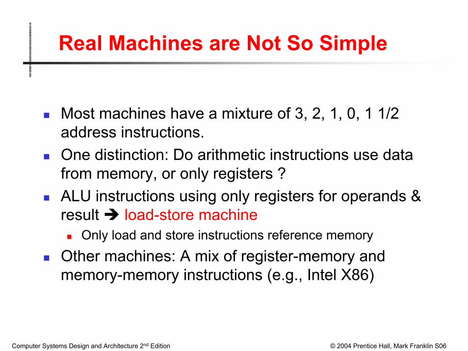
Most machines have a mixture of 3, 2, 1, 0, 1 1/2 address instructions.One distinction: Do arithmetic instructions use data from memory, or only registers ?ALU instructions using only registers for operands & result load-store machine
Only load and store instructions reference memory
Other machines: A mix of register-memory and memory-memory instructions (e.g., Intel X86)
Computer Systems Design and Architecture 2nd Edition © 2004 Prentice Hall, Mark Franklin S06
Addressing Modes
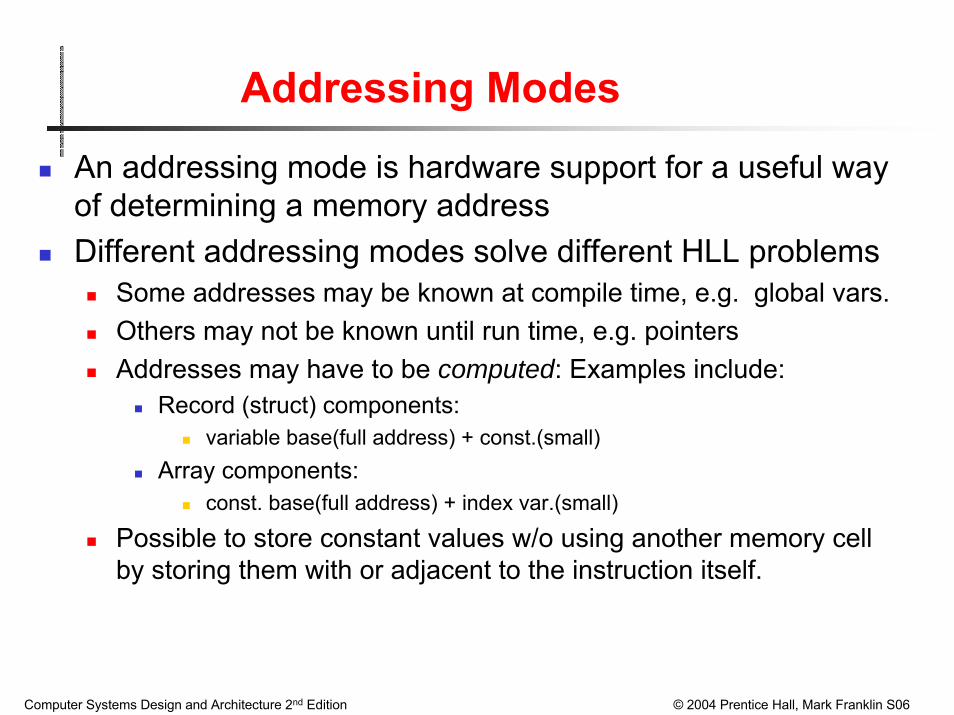
An addressing mode is hardware support for a useful way of determining a memory addressDifferent addressing modes solve different HLL problems
Some addresses may be known at compile time, e.g. global vars.Others may not be known until run time, e.g. pointersAddresses may have to be computed: Examples include:
Record (struct) components:variable base(full address) + const.(small)
Array components:const. base(full address) + index var.(small)
Possible to store constant values w/o using another memory cell by storing them with or adjacent to the instruction itself.
Computer Systems Design and Architecture 2nd Edition © 2004 Prentice Hall, Mark Franklin S06
HLL Examples of Structured Addresses
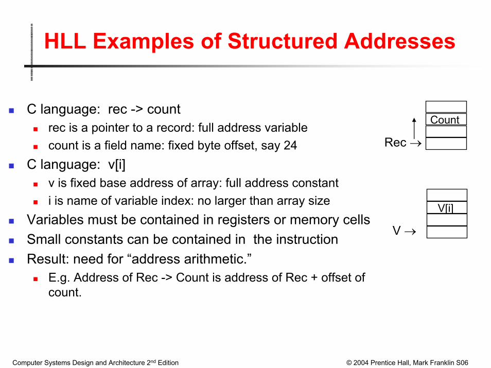
C language: rec -> countrec is a pointer to a record: full address variablecount is a field name: fixed byte offset, say 24
C language: v[i]v is fixed base address of array: full address constanti is name of variable index: no larger than array size
Variables must be contained in registers or memory cellsSmall constants can be contained in the instructionResult: need for “address arithmetic.”
E.g. Address of Rec -> Count is address of Rec + offset of count.
Rec →
Count
V →
V[i]
Computer Systems Design and Architecture 2nd Edition © 2004 Prentice Hall, Mark Franklin S06
Processor Organization
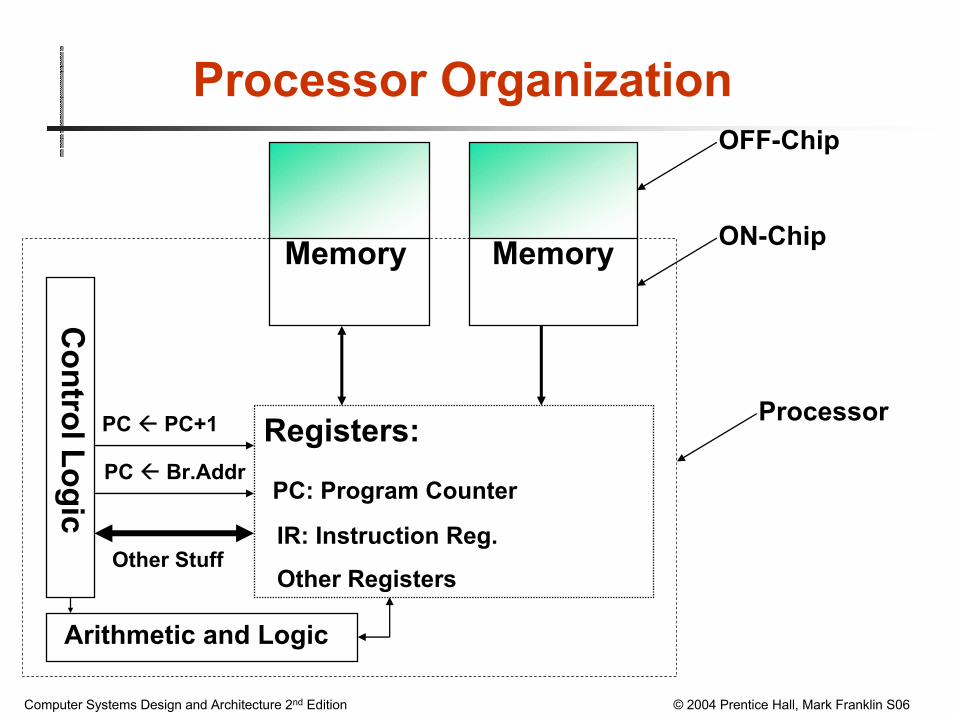
Instruction Memory
Registers:
PC: Program Counter
IR: Instruction Reg.
Other Registers
PC PC+1
Control Logic
PC Br.Addr
Other Stuff
Data Memory
OFF-Chip
ON-Chip
Arithmetic and Logic
Processor

Computer Systems Design and Architecture 2nd Edition © 2004 Prentice Hall, Mark Franklin S06
Addressing Modes
Why do we need different addressing modes ?Why isn’t a direct addressing mode sufficient ?
Memory
Load R1, 1024
1024237R1 237
Computer Systems Design and Architecture 2nd Edition © 2004 Prentice Hall, Mark Franklin S06
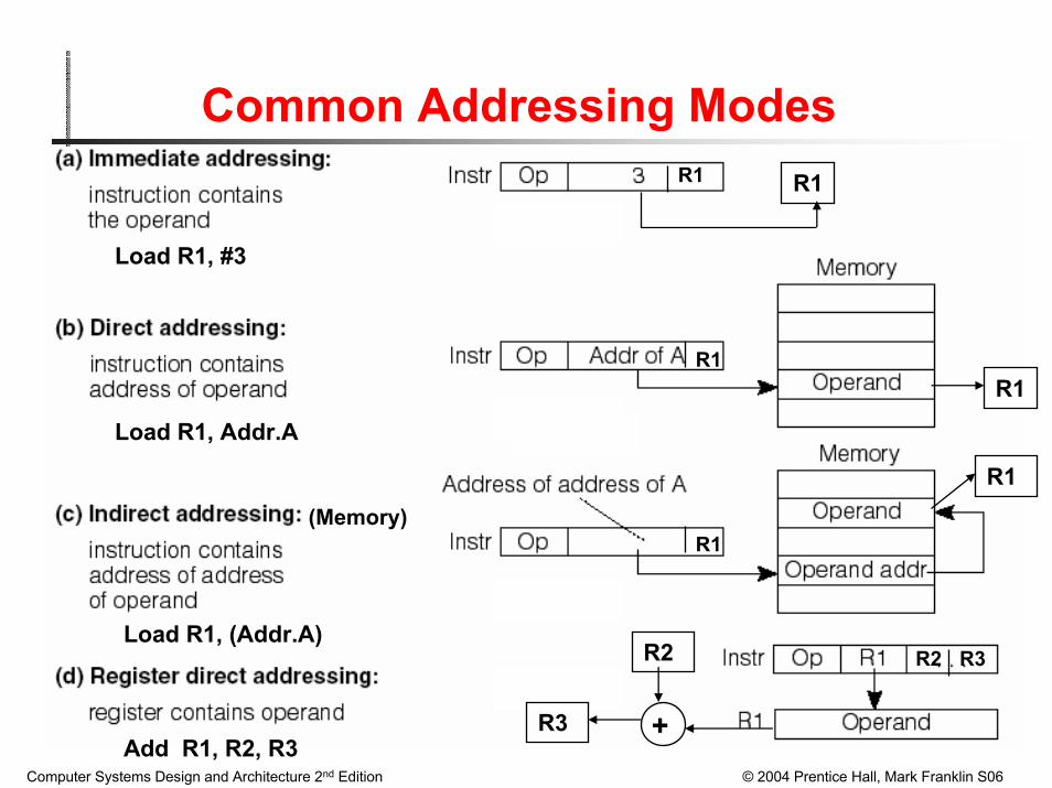
Common Addressing Modes
Load R1, #3
Load R1, Addr.A
Load R1, (Addr.A)
Add R1, R2, R3
R1
R1R1
R1
R2
+R3
R1
R1
R2 R3
(Memory)

Computer Systems Design and Architecture 2nd Edition © 2004 Prentice Hall, Mark Franklin S06
Common Addressing Modes
Load R1, (R2)
Load R1, 4[R2]
LoadRel R1, 4[PC]
R1
R1
R1
R1
R1
R1

Computer Systems Design and Architecture 2nd Edition © 2004 Prentice Hall, Mark Franklin S06
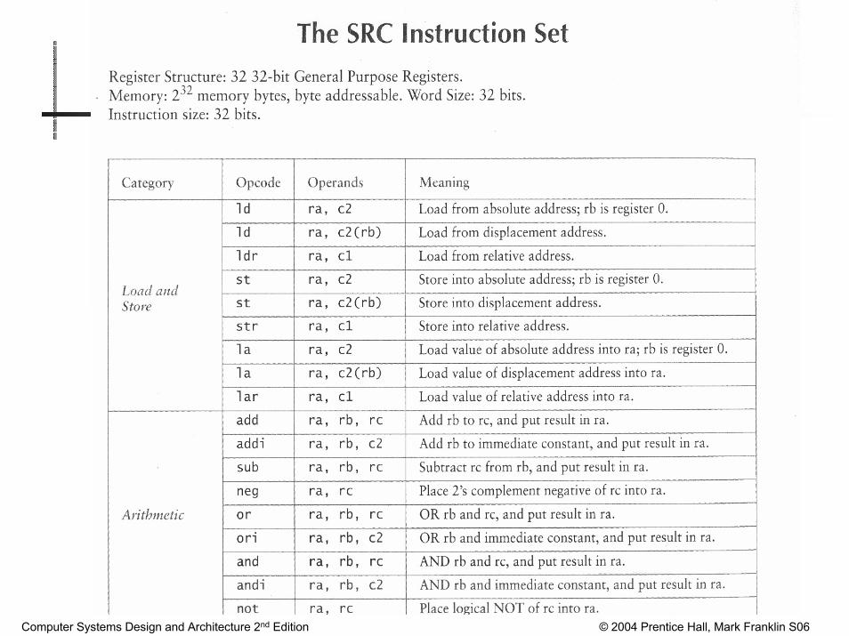
SRC: Simple RISC Computer
32 general purpose registers of 32 bits32 bit program counter, PC and instruction reg., IR232 bytes of memory address space

Computer Systems Design and Architecture 2nd Edition © 2004 Prentice Hall, Mark Franklin S06
SRC Characteristics
(=) Similar to commercial RISC machines(–) Less powerful than commercial RISC machines.
(=) Load-store design: Memory access is through load & store instructions(–) Operation on 32-bit words only, no byte or half-word operations.(=) Only a few addressing modes are supported(=) ALU Instructions are 3-register type(–) Branch instructions can branch unconditionally or conditionally on whether the value in a specified register is = 0, <> 0, >= 0, or < 0.(–) Branch-and-link instructions are similar, but leave the value of current PC in any register, useful for procedure/subroutine return.(–) Can only branch to an address in a register, no direct addressing.(=) All instructions are 32-bits (1-word) long (going to 64-bits)
Computer Systems Design and Architecture 2nd Edition © 2004 Prentice Hall, Mark Franklin S06
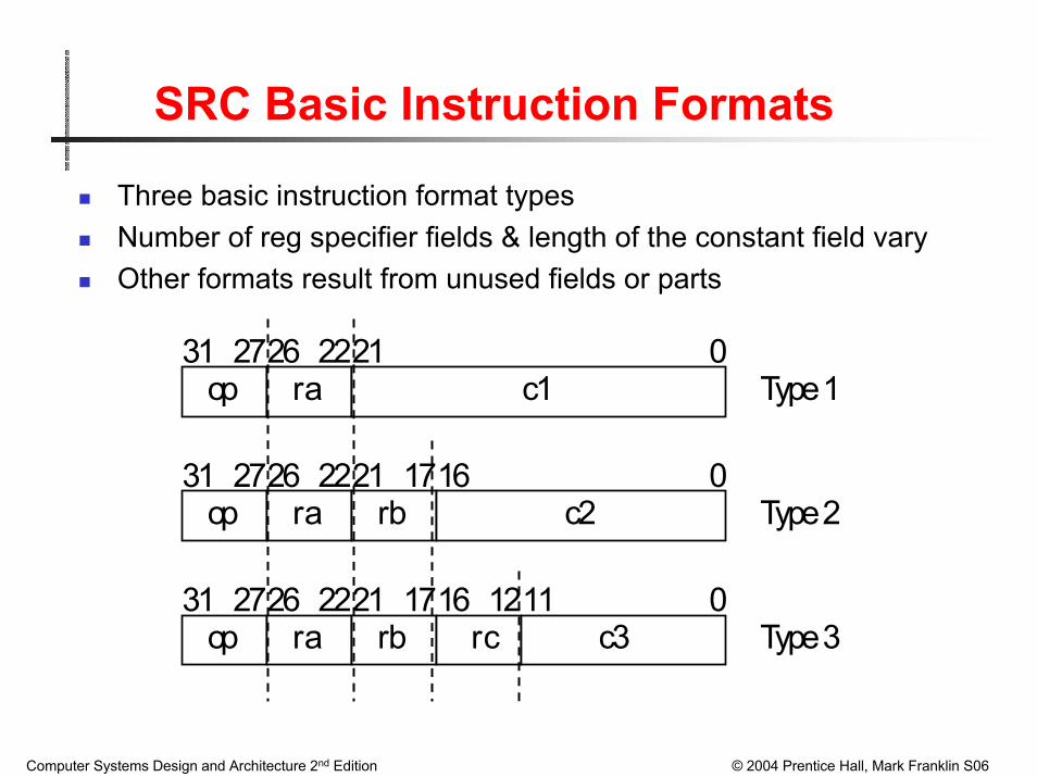
SRC Basic Instruction Formats
Three basic instruction format typesNumber of reg specifier fields & length of the constant field varyOther formats result from unused fields or parts
31 2726 2221 0
31 27
27
26
26
22
22
21
2131
1716
1716 1211
0
0
op ra
rb
rcrb
ra
ra
op
op
c1
c2
c3
Type 1
Type 2
Type 3
Computer Systems Design and Architecture 2nd Edition © 2004 Prentice Hall, Mark Franklin S06
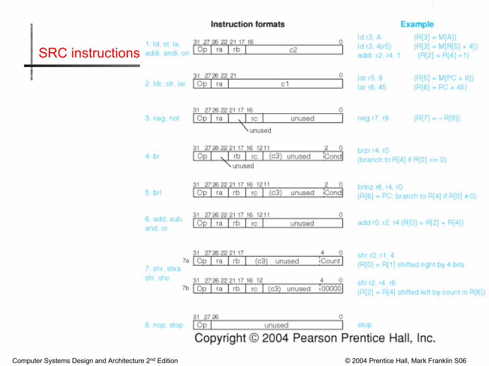
SRC instructions
Computer Systems Design and Architecture 2nd Edition © 2004 Prentice Hall, Mark Franklin S06
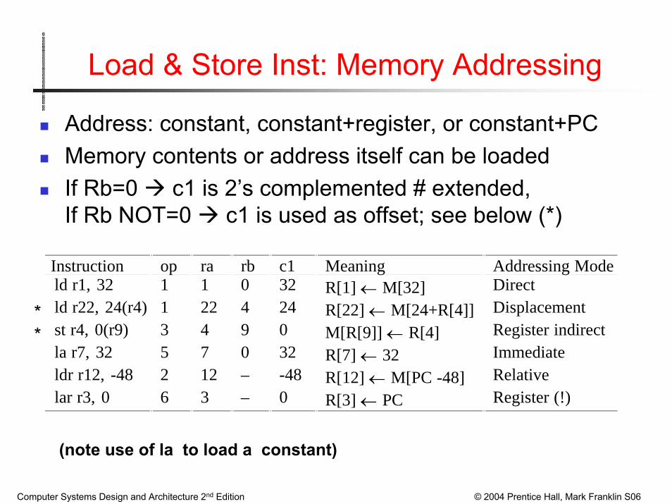
Load & Store Inst: Memory Addressing
Address: constant, constant+register, or constant+PCMemory contents or address itself can be loadedIf Rb=0 c1 is 2’s complemented # extended, If Rb NOT=0 c1 is used as offset; see below (*)
Instruction op ra rb c1 Meaning Addressing Modeld r1, 32 1 1 0 32 R[1] ← M[32] Directld r22, 24(r4) 1 22 4 24 R[22] ← M[24+R[4]] Displacementst r4, 0(r9) 3 4 9 0 M[R[9]] ← R[4] Register indirectla r7, 32 5 7 0 32 R[7] ← 32 Immediateldr r12, -48 2 12 – -48 R[12] ← M[PC -48] Relativelar r3, 0 6 3 – 0 R[3] ← PC Register (!)
**
(note use of la to load a constant)

Computer Systems Design and Architecture 2nd Edition © 2004 Prentice Hall, Mark Franklin S06
Binary Encoding of Instructions
Example: ld r22, 24(24)
op=1 ra=22 rb=4 c1=24 00001 10110 00100 00000000000011000

Computer Systems Design and Architecture 2nd Edition © 2004 Prentice Hall, Mark Franklin S06
Assembly Language for Arithmetic & Logic Instr
Format Example Meaningneg ra, rc neg r1, r2 ;Negate (r1 = -r2) not ra, rc not r2, r3 ;Not (r2 = r3´ )add ra, rb, rc add r2, r3, r4 ;2’s complement additionsub ra, rb, rc ;2’s complement subtractionand ra, rb, rc ;Logical andor ra, rb, rc ;Logical oraddi ra, rb, c2 addi r1, r3, 1 ;Immediate 2’s complement addandi ra, rb, c2 ;Immediate logical andori ra, rb, c2 ;Immediate logical or
NOTE: Immediate subtract not needed since constant in addi may be negative
Computer Systems Design and Architecture 2nd Edition © 2004 Prentice Hall, Mark Franklin S06
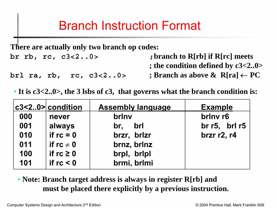
Branch Instruction FormatThere are actually only two branch op codes:br rb, rc, c3<2..0> ;branch to R[rb] if R[rc] meets
; the condition defined by c3<2..0>brl ra, rb, rc, c3<2..0> ; Branch as above & R[ra] ← PC
• It is c3<2..0>, the 3 lsbs of c3, that governs what the branch condition is:
c3<2..0> condition Assembly language Example000 never brlnv brlnv r6001 always br, brl br r5, brl r5010 if rc = 0 brzr, brlzr brzr r2, r4011 if rc ≠ 0 brnz, brlnz100 if rc ≥ 0 brpl, brlpl101 if rc < 0 brmi, brlmi
• Note: Branch target address is always in register R[rb] and must be placed there explicitly by a previous instruction.
Computer Systems Design and Architecture 2nd Edition © 2004 Prentice Hall, Mark Franklin S06
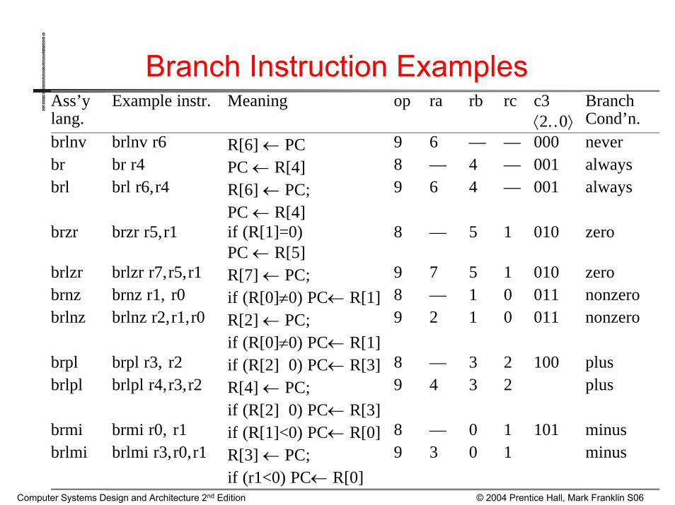
Branch Instruction ExamplesAss’ylang.
Example instr. Meaning op ra rb rc c3⟨2..0⟩
BranchCond’n.
brlnv brlnv r6 R[6] ← PC 9 6 — — 000 neverbr br r4 PC ← R[4] 8 — 4 — 001 alwaysbrl brl r6,r4 R[6] ← PC;
PC ← R[4]9 6 4 — 001 always
brzr brzr r5,r1 if (R[1]=0)PC ← R[5]
8 — 5 1 010 zero
brlzr brlzr r7,r5,r1 R[7] ← PC; 9 7 5 1 010 zerobrnz brnz r1, r0 if (R[0]≠0) PC← R[1] 8 — 1 0 011 nonzerobrlnz brlnz r2,r1,r0 R[2] ← PC;
if (R[0]≠0) PC← R[1]9 2 1 0 011 nonzero
brpl brpl r3, r2 if (R[2]� 0) PC← R[3] 8 — 3 2 100 plusbrlpl brlpl r4,r3,r2 R[4] ← PC;
if (R[2]� 0) PC← R[3]9 4 3 2 plus
brmi brmi r0, r1 if (R[1]<0) PC← R[0] 8 — 0 1 101 minusbrlmi brlmi r3,r0,r1 R[3] ← PC;
if (r1<0) PC← R[0]9 3 0 1 minus
Computer Systems Design and Architecture 2nd Edition © 2004 Prentice Hall, Mark Franklin S06
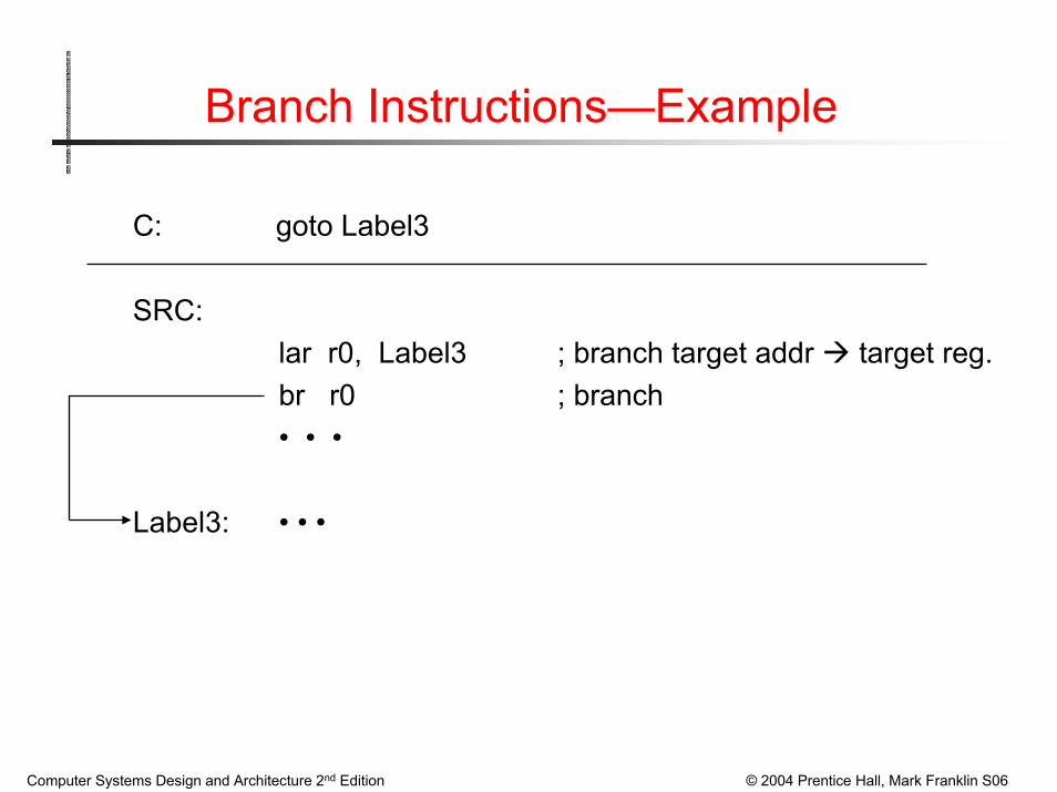
Branch Instructions—Example
C: goto Label3
SRC:lar r0, Label3 ; branch target addr target reg. br r0 ; branch• • •
Label3: • • •

Computer Systems Design and Architecture 2nd Edition © 2004 Prentice Hall, Mark Franklin S06
Example of conditional branch
in C: #define Cost =125if (X<0) then X = -X;
-------------------------------------------------------------------------------------------in SRC:Cost .equ 125 ;define symbolic constant
.org 1000 ;next word will be loaded at address 100010
X: .dw 1 ;reserve 1 word for variable X.org 5000 ;program will be loaded at location 500010
lar r31, Over ;load address of “false” jump locationld r1, X ;load value of X into r1brpl r31, r1 ;branch to Else if r1≥0neg r1, r1 ;negate value
Over: • • • ;continue
Assembler Directives
Computer Systems Design and Architecture 2nd Edition © 2004 Prentice Hall, Mark Franklin S06

Computer Systems Design and Architecture 2nd Edition © 2004 Prentice Hall, Mark Franklin S06

Computer Systems Design and Architecture 2nd Edition © 2004 Prentice Hall, Mark Franklin S06

Computer Systems Design and Architecture 2nd Edition © 2004 Prentice Hall, Mark Franklin S06
Assembling & SRC Machine Simulation
Go to ftp site: ftp://schof.colorado.edu/pub/CSDAClick on “Simulators and Models”.Download file: SRCToolsv.3.0.8.jar
Right click mouse, select “Save link target as ..”Download file: README
Right click mouse, select “Save link target as ..”Create shortcut to running assembler & simulator (windows processors)
In your file, right click on “SRCToolsv.3.0.8.jar”, Click on “Create shortcut”
To run assembler & simulator click on shortcut you have createdNOTE: Along the way if you don’t already have a JAVA interpreter on your processor, that will have to be installed.