Embed Size (px)
Citation preview
Chapter 2
Pipelining
1
Database Systems and Modern CPU Architecture© 2009 • Prof. Dr. Torsten Grust
Pipelining in CPUs
• Pipelining is an CPU implementation technique
whereby multiple instructions are overlapped in
execution.
• Think of a factory assembly line — each step in the
pipeline completes a part of an instruction.
• Pipelining thus takes advantage of parallelism that
exists among the actions to execute an instruction
(instruction-level parallelism, ILP).
2
2

Database Systems and Modern CPU Architecture© 2009 • Prof. Dr. Torsten Grust
Pipelining in CPUs
• Pipeline stages are hooked together. Each stage must
be ready to proceed at the same time.
• Processor cycle: time required between moving an
instruction one step down the pipeline.
Usually: 1 processor cycle = 1 CPU clock cycle
- The slowest pipeline stage thus determines the
length of the processor cycle.
3
3
Database Systems and Modern CPU Architecture© 2009 • Prof. Dr. Torsten Grust
Throughput
• Throughput of the instruction pipeline: How often
does an instruction exit the pipeline?
• Pipelining aims to reduce the average execution time
per instruction (CPI). Ideally:
CPIpipeline = CPI / # of pipeline stages
- But: pipelining involves some overhead and the
available ILP may be lower than ideal.
4
4

Database Systems and Modern CPU Architecture© 2009 • Prof. Dr. Torsten Grust
Implementing a
RISC Instruction Set
• To understand how a RISC instruction set can be
implemented in a pipelined fashion, first consider its
implementation without pipelining.
- Focus on load-store, branch, and integer ALU
operations.
• In the non-pipelined implementation, each instruction
takes (at most) 5 processor cycles.
5
5
Database Systems and Modern CPU Architecture© 2009 • Prof. Dr. Torsten Grust
Five CPU Clock Cycles
1. Instruction Fetch Cycle (IF):
Send PC to memory, fetch current instruction.
PC ← PC + 4.
2. Instruction Decode/Register Fetch Cycle (ID):
Decode instruction and read source registers from
register file. Do equality test on registers (for branch).
Compute branch target address A by adding to PC.
Branch can be completed now (PC ← A).
6
6

Database Systems and Modern CPU Architecture© 2009 • Prof. Dr. Torsten Grust
Five CPU Clock Cycles
3. Execution/Effective Address Cycle (EX):
ALU operates on operands prepared in cycle ID to
perform one of the following:
3.(a) Memory reference: add base register and offset to
form effective address (no memory access yet).
3.(b) Register-register ALU operation: perform arith/logical
operation on values read from register file.
3.(c) Register-immediate ALU operation: perform arith/
logical operation on value read from register file and
the immediate.
7
7
Database Systems and Modern CPU Architecture© 2009 • Prof. Dr. Torsten Grust
Five CPU Clock Cycles
4. Memory Access Cycle (MEM):
4.(a) Instruction is a load: memory performs read at
effective address computed in cycle EX.
4.(b) Instruction is a store: memory performs a write at
effective address computed in cycle EX.
5. Write-back Cycle (WB):
Register-register ALU or load instruction: write result
back into register file.
8
8

Database Systems and Modern CPU Architecture© 2009 • Prof. Dr. Torsten Grust
Implementing a
RISC Instruction Set• In this non-pipelined implementation,
- branch instructions require 2 cycles,
- store instructions require 4 cycles,
- all other instructions require 5 cycles.
• Assume branch frequency of 12%, store frequency of
10%:
CPI = 4.54
9
9
Database Systems and Modern CPU Architecture© 2009 • Prof. Dr. Torsten Grust
Five-Stage Pipeline for RISC
• Pipeline the execution just described by simply
starting a new instruction on each clock cycle.
• Each cycle becomes a pipeline stage:
10
Clock nummber
Instruction 1 2 3 4 5 6 7 8 9i IF ID EX MEM WB
i+1 IF ID EX MEM WBi+2 IF ID EX MEM WBi+3 IF ID EX MEM WBi+4 IF ID EX MEM WB
10

Database Systems and Modern CPU Architecture© 2009 • Prof. Dr. Torsten Grust
Five-Stage Pipeline for RISC
• Pipelining needs to make sure that the same CPU
resource is not asked to perform different operations in
the same clock cycle.
- For example, ALU cannot be asked to compute an
effective address and perform a subtract at the same
time.
• Fortunately, the simplicity of RISC makes such conflict
evaluation relatively easy.
11
11
© 2009 • Prof. Dr. Torsten Grust Database Systems and Modern CPU Architecture
RISC Data Paths
12
12

Database Systems and Modern CPU Architecture© 2009 • Prof. Dr. Torsten Grust
RISC Data Paths
13
• Register file (Reg) is used in two stages, ID and WB.
- Read Reg in first half of clock cycle, write Reg in
second half.
• Not shown: incrementing PC (in IF stage); adder to
compute branch target address.
• Problem: new PC after branch only known after ID
stage. “Too late” for instruction immediately following
the branch.
13
Database Systems and Modern CPU Architecture© 2009 • Prof. Dr. Torsten Grust
Pipeline Registers
• At the end of a clock cycle, each pipe stage stores its
intermediate result in a pipeline register:
1. Connect pipeline stages,
2. avoid interference of adjacent pipeline stages, and
3. transport intermediate results between non-
adjacent stages
(e.g., execution of SD: read Reg in stage ID, write to
DM in stage MEM).
14
14

© 2009 • Prof. Dr. Torsten Grust Database Systems and Modern CPU Architecture
Pipeline Registers
15
15
Database Systems and Modern CPU Architecture© 2009 • Prof. Dr. Torsten Grust
Pipeline Hazards
16
• Hazards prevent the next instruction in the instruction
stream from executing in its designated clock cycle.
1. Structural hazards: resource conflict (e.g., ALU);
hardware cannot support all possible combinations
of overlapped instructions.
2. Data hazards: instruction depends on the result of a
previous instruction.
3. Control hazards: arise from pipelining of instructions
that change the PC (branches).
16
Database Systems and Modern CPU Architecture© 2009 • Prof. Dr. Torsten Grust
Pipeline Stalls
• Occurrence of hazards lead to need for pipeline stalls:
- Delay hazardous instruction i (and instructions
i+1, i+2, ...) until hazard condition clears —
instructions i-1, i-2, ... proceed normally.
- No new instructions are fetched/allowed to enter
the pipeline during the stall.
• Such stalls increase the CPI from the ideal value of 1.
17
17
Database Systems and Modern CPU Architecture© 2009 • Prof. Dr. Torsten Grust
Structural Hazards
• Overlapped instruction execution requires duplication
of functional units to allow all possible combinations
of instructions in the pipeline.
• Structural hazards occur if
- some functional unit is not fully pipelined, or
- some resource has not been duplicated enough (e.g.,
the CPU memory write port).
18
18

© 2009 • Prof. Dr. Torsten Grust Database Systems and Modern CPU Architecture
Structural Hazard
(here: IF vs. MEM)
19
19
Database Systems and Modern CPU Architecture© 2009 • Prof. Dr. Torsten Grust
Resolving Structural Hazards
20
• To resolve this hazard, either
- provide the CPU with separate instruction and data
memory ports (leads to double memory bandwidth
requirements), or
- stall the pipeline for 1 clock cycle.
The stall floats through the pipeline like a “bubble”,
taking space but carrying no useful work.
20

© 2009 • Prof. Dr. Torsten Grust Database Systems and Modern CPU Architecture
Inserting a Pipeline Stall
21
Clocck nummberInstruction 1 2 3 4 5 6 7 8 9 10
i IF ID EX MEM WBi+1 IF ID EX MEM WBi+2 IF ID EX MEM WBi+3 stall IF ID EX MEM WBi+4 IF ID EX MEM WBi+5 IF ID EX MEMi+6 IF ID EX
• No instruction is initiated at clock cycle 4.
• No instruction completes at clock cycle 8.
• Instruction i+3 does not start execution until
clock cycle 5.
21
Database Systems and Modern CPU Architecture© 2009 • Prof. Dr. Torsten Grust
Data Hazards
22
• Pipelining changes the relative timing of instructions
by overlapping their execution.
• This can introduce data hazards:
The order of read/write accesses to operands in the
pipeline can differ from strict sequential execution
order. Consider:
DADD R1,R2,R3
DSUB R4,R1,R5
AND R6,R1,R7
OR R8,R1,R9
XOR R10,R1,R11
22

© 2009 • Prof. Dr. Torsten Grust Database Systems and Modern CPU Architecture
Data Hazards
23
23
Database Systems and Modern CPU Architecture© 2009 • Prof. Dr. Torsten Grust
Data Hazards
24
• The DADD does not write R1 before its WB stage:
1. DSUB may non-deterministically see the R1 value
before or after the DADD (interrupt).
2. AND is affected in a similar fashion.
3. XOR and OR will operate properly.
• The unpredictable behavior of 1. clearly is
inacceptable.
24

Database Systems and Modern CPU Architecture© 2009 • Prof. Dr. Torsten Grust
Minimizing Stalls
by Forwarding• A simple hardware technique — forwarding — can
clear the DSUB and AND data hazard conditions.
• Key insight:
- DSUB does not really need the result until after the
DADD actually produces it.
- Forward from pipeline registers to the ALU:
EX/MEM ALU MEM/WB ALU
25
25
© 2009 • Prof. Dr. Torsten Grust Database Systems and Modern CPU Architecture
Forwarding
26
26

Database Systems and Modern CPU Architecture© 2009 • Prof. Dr. Torsten Grust
Forwarding
27
• Special forwarding hardware detects that a previous
ALU operation has written a register that corresponds
to a source for the current ALU operation:
- Control logic then selects forwarded results (rather
than the value read from the register file).
- Forwarding may span more than one instruction.
- Forwarding can go to either (or both) ALU inputs.
Example: replace AND R6,R1,R7 by AND R6,R1,R4.
27
© 2009 • Prof. Dr. Torsten Grust Database Systems and Modern CPU Architecture
Generalized Forwarding
28
DADD R1,R2,R3
LD R4,0(R1)
SD R4,12(R1)
MEM/WB DM
28

Database Systems and Modern CPU Architecture© 2009 • Prof. Dr. Torsten Grust
Data Hazards and
Unavoidable Stalls
29
• Unfortunately, not all potential data hazards can be
handled by forwarding. Consider:
- Note: The first instruction in the sequence now is LD
(was: DADD).
LD R1,0(R2)
DSUB R4,R1,R5
AND R6,R1,R7
OR R8,R1,R9
29
© 2009 • Prof. Dr. Torsten Grust Database Systems and Modern CPU Architecture
No Forwarding “Back in Time”
30
30

Database Systems and Modern CPU Architecture© 2009 • Prof. Dr. Torsten Grust
Pipeline Interlocks
31
• The value loaded from memory is not available until
LD’s 4th clock cycle (MEM).
• The load instruction has a delay (latency) that cannot
be eliminated by forwarding hardware.
• Instead, recent CPUs introduce a pipeline interlock to
stall the pipeline until the hazard has cleared.
The CPI for the stalled instruction increases by the
length of the stall (here: 1).
31
© 2009 • Prof. Dr. Torsten Grust Database Systems and Modern CPU Architecture
Pipeline Interlock Stalls
32
Cloocck nummber
Instruction 1 2 3 4 5 6 7 8 9
LD R1,0(R2) IF ID EX MEMM WB
DSUB R4,R1,R5 IF ID EX MEMM WB
AND R6,R1,R7 IF ID EX MEMM WB
OR R8,R1,R9 IF ID EX MEM WB
LD R1,0(R2) IF ID EX MEM WB
DSUB R4,R1,R5 IF ID stall EX MEM WB
AND R6,R1,R7 IF stall ID EX MEM WB
OR R8,R1,R9 stall IF ID EX MEM WB
32

Database Systems and Modern CPU Architecture© 2009 • Prof. Dr. Torsten Grust
Control Hazards
33
• Control (or branch) hazards are even more severe than
data hazards.
• An untaken branch does not affect the PC
(other than the regular PC ← PC + 4 in stage IF).
• A taken branch affects the PC, but does not do so until
the end of the branch’s 2nd clock cycle (ID).
33
Database Systems and Modern CPU Architecture© 2009 • Prof. Dr. Torsten Grust
Redo Instruction Fetch
• A simple way to deal with such control hazards is to
redo instruction fetch once the CPU knows whether
the branch is taken:
34
Clocck nummber
Instruction 1 2 3 4 5 6 7
Branch instruction IF ID EX MEM WB
Branch successor IF IF ID EX MEM WB
Branch successor + 1 IF ID EX MEM
• Note: If the branch is untaken, the IF is redundant.
The IF essentially is a stall.
34

Database Systems and Modern CPU Architecture© 2009 • Prof. Dr. Torsten Grust
Reducing Pipeline
Branch Penalties
• One wasted cycle per branch will yield a performance
loss of 10%–20% (depending on branch frequency).
• Better pipeline schemes try to predict whether a branch
will be taken or untaken.
• Simple variant: CPU predicts every branch as untaken—
high-level PL compiler can then arrange code to match
the CPU’s simple prediction scheme.
35
35
© 2009 • Prof. Dr. Torsten Grust Database Systems and Modern CPU Architecture
Predicted-Untaken Scheme
36
Clocck nummber
Instruction 1 2 3 4 5 6 7 8
Untaken branch i IF ID EX MEM WB
Instruction i+1 IF ID EX MEM WB
Instruction i+2 IF ID EX MEM WB
Instruction i+3 IF ID EX MEM WB
Taken branch i IF ID EX MEM WB
Instruction i+1 IF idle idle idle idle
Branch target IF ID EX MEM WB
Branch target + 1 IF ID EX MEM WB
36

Database Systems and Modern CPU Architecture© 2009 • Prof. Dr. Torsten Grust
Delayed Branches
37
• Consider the following instruction sequence:
BEQZ R2,label
DADD R1,R2,R3
label: SD R1,0(R4)
• A CPU with delayed branches will execute the
DADD R1,R2,R3 even if the branch to label is taken!
• The instruction immediately behind the branch is in the
branch delay slot.
37
© 2009 • Prof. Dr. Torsten Grust Database Systems and Modern CPU Architecture
Delayed Branches
38
Clock nummber
Instruction 1 2 3 4 5 6 7 8
Untaken branch i IF ID EX MEM WB
Branch delay instruction i+1 IF ID EX MEM WB
Instruction i+2 IF ID EX MEM WB
Instruction i+3 IF ID EX MEMM WB
Taken branch i IF ID EX MEM WB
Branch delay instruction i+1 IF ID EX MEM WB
Branch target IF ID EX MEM WB
Branch target + 1 IF ID EX MEM WB
38

Database Systems and Modern CPU Architecture© 2009 • Prof. Dr. Torsten Grust
Scheduling the
Branch Delay Slot
39
• It is the job of the compiler to fill the branch delay slot
with a valid and useful instruction.
- Valid? What should happen if the branch delay slot is
filled with a taken branch?
- Useful? Depending on the instruction context,
different scheduling strategies are possible.
(Normally this is forbidden.)
39
Database Systems and Modern CPU Architecture© 2009 • Prof. Dr. Torsten Grust
Scheduling the
Branch Delay Slot
• The best possible solution: Schedule an independent
instruction from before the branch:
40
DADD R1,R2,R3
BEQZ R2,label
label:
BEQZ R2,label
DADD R1,R2,R3
label:
40

Database Systems and Modern CPU Architecture© 2009 • Prof. Dr. Torsten Grust
Scheduling the
Branch Delay Slot• Schedule (copy) an instruction from the branch target
(note: the dependent DADD cannot be scheduled):
41
label: DSUB R4,R5,R6
DADD R1,R2,R3
BEQZ R1,label
DSUB R4,R5,R6
label:
DADD R1,R2,R3
BEQZ R1,label
DSUB R4,R5,R6
• Profitable if branch is likely to be taken — if untaken,
executing DSUB must not affect program correctness.
41
Database Systems and Modern CPU Architecture© 2009 • Prof. Dr. Torsten Grust
Nullifying Branches
• CPUs support branch delay slot scheduling via
nullifying (or cancelling) branches.
• MIPS: BcccL (branch on condition ccc likely).
42
DSUB R4,R5,R6
label:
DADD R1,R2,R3
BEQL R1,R0,label
DSUB R4,R5,R6
SD R4,...
Instruction in delay
slot cancelled if
branch not taken
42

Database Systems and Modern CPU Architecture© 2009 • Prof. Dr. Torsten Grust
Pipelining and
Multi-Cycle Operations
• If we also consider floating-point (FP) operations, we
need to handle multi-cycle stages in CPU pipelines.
- Insisting on FP operation completion in one cycle
would mean to accept a slow clock.
• Try to model (the latency of ) the FP units on the CPU
and fit them into the IF–ID–EX–MEM–WB pipeline
scheme.
43
43
Database Systems and Modern CPU Architecture© 2009 • Prof. Dr. Torsten Grust
Latencies and Initiation
Intervals for Functional Units• Latency: number of intervening cycles between
producing and consuming instruction.
• Initiation interval: number of cycles that must elapse between issuing two operations of the same type.
44
Functional Unit Latency Initiation Interval
Integer ALU 0 1
FP add 3 1
FP/integer multiply 6 1
FP/integer divide 24 25
44

© 2009 • Prof. Dr. Torsten Grust Database Systems and Modern CPU Architecture
Pipeline with
FP Functional Units
45
45
Database Systems and Modern CPU Architecture© 2009 • Prof. Dr. Torsten Grust
Pipeline with
FP Functional Units
46
• Note: Multiplier and adder stages (M1, M2, ...., A1, A2, ...)
are named separately to indicate independence (need
pipeline registers Mi/M(i+1), etc.).
• The FP divide unit DIV is not pipelined: only a single
divide operation may be active at a time.
• CPU design dilemma:
Higher clock rate
less logic in each pipe stage
longer latency for operations.
46

© 2009 • Prof. Dr. Torsten Grust Database Systems and Modern CPU Architecture
Pipeline Timing for
Independent FP Operations
47
Clocck nummber
Instruction 1 2 3 4 5 6 7 8 9 10 11
MUL.D IF ID M1 M2 M3 M4 M5 M6 M7 MMEM WB
ADD.D IF ID A1 A2 A3 A4 MMEM WB
L.D IF ID EX MEM WB
ADD IF ID EX MMEM WB
• The .D operation suffix indicates a 64-bit (double
precision) FP operation.
• Stage: stage where data is needed for operation
Stage: stage where result is available
47
Database Systems and Modern CPU Architecture© 2009 • Prof. Dr. Torsten Grust
Hazards in
Longer Latency Pipelines
48
1. Unit DIV is not fully pipelined: structural hazards
(detect, stall issuing instruction).
2. Instructions have varying running times: multiple
instructions may be in WB (register file write) stage.
3. Instructions can complete in different order than they
were issued.
48
Database Systems and Modern CPU Architecture© 2009 • Prof. Dr. Torsten Grust
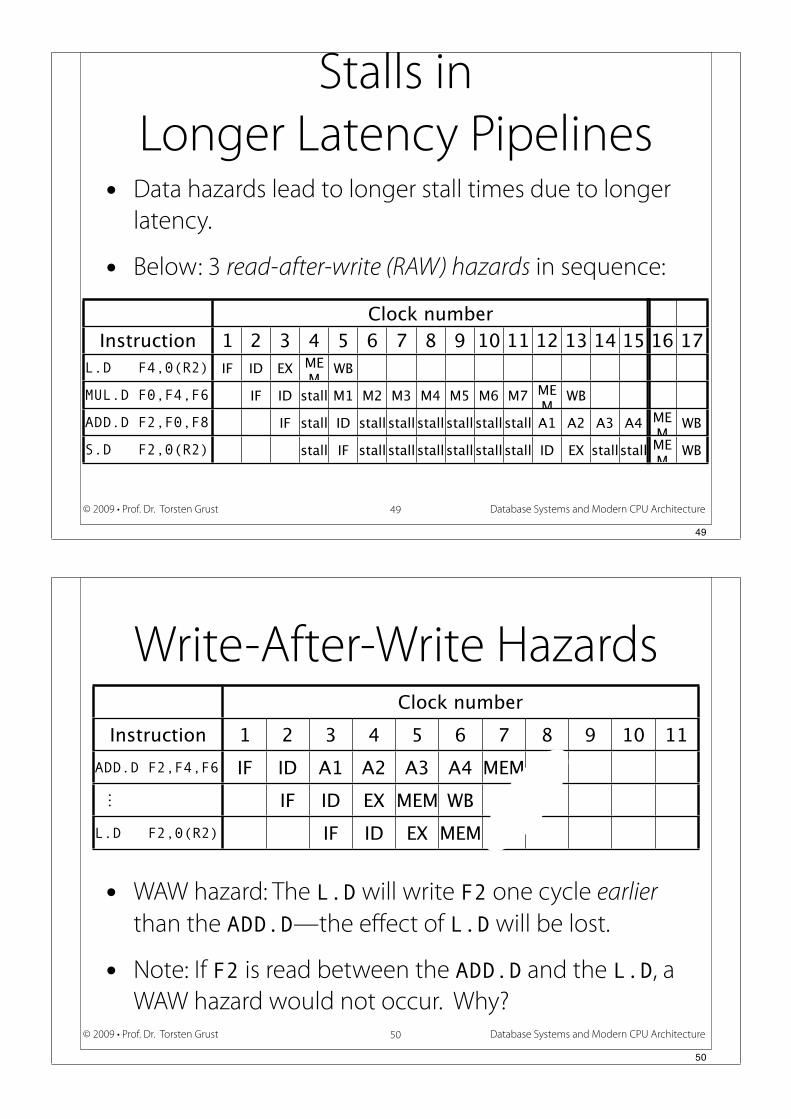
Stalls in
Longer Latency Pipelines
49
Clockk numbber
Instruction 1 2 3 4 5 6 7 8 9 10 11 12 13 14 15
L.D F4,0(R2) IF ID EX MEM
WB
MUL.D F0,F4,F6 IF ID stall M1 M2 M3 M4 M5 M6 M7 MEM
WB
ADD.D F2,F0,F8 IF stall ID stall stall stall stall stall stall A1 A2 A3 A4
S.D F2,0(R2) stall IF stall stall stall stall stall stall ID EX stallstall
16 17
MEM
WB
MEM
WB
• Data hazards lead to longer stall times due to longer
latency.
• Below: 3 read-after-write (RAW) hazards in sequence:
49
Database Systems and Modern CPU Architecture© 2009 • Prof. Dr. Torsten Grust
Write-After-Write Hazards
• WAW hazard: The L.D will write F2 one cycle earlier
than the ADD.D—the effect of L.D will be lost.
• Note: If F2 is read between the ADD.D and the L.D, a
WAW hazard would not occur. Why?
50
Clockk nummber
Instruction 1 2 3 4 5 6 7 8 9 10 11
ADD.D F2,F4,F6 IF ID A1 A2 A3 A4 MEM WB
IF ID EX MEM WB
L.D F2,0(R2) IF ID EX MEM WB
50

Database Systems and Modern CPU Architecture© 2009 • Prof. Dr. Torsten Grust
Do WAW Hazards Occur?
• Will a compiler ever schedule two writes to the same
destination register without any intervening read?
- Yes, if the instruction sequence does not match the
compiler’s expectation. Consider:
51
BNEZ R1,exit
DIV.D F0,F2,F4
exit: LD.D F0,0(R2)
51
Database Systems and Modern CPU Architecture© 2009 • Prof. Dr. Torsten Grust
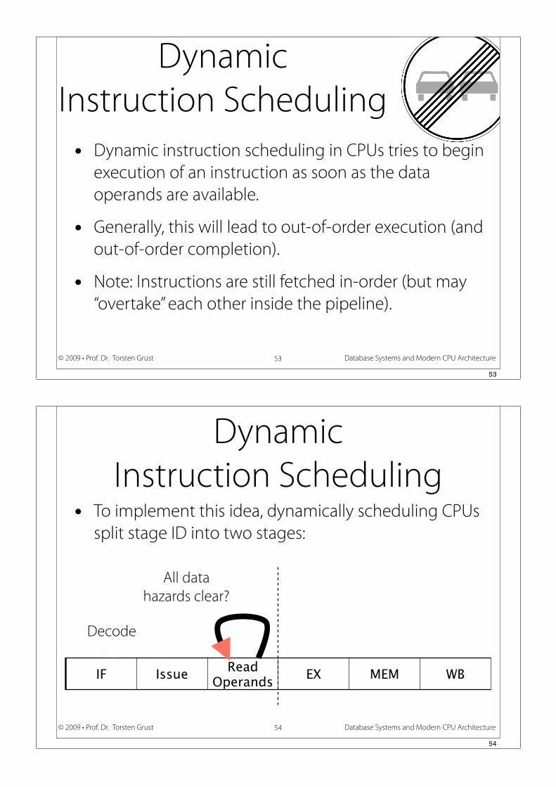
Dynamic
Instruction Scheduling• Up to here,
1. the compiler statically scheduled instructions to
avoid hazards that cannot be hidden by hardware
(e.g., via forwarding), and
2. CPUs issued instruction in order: if an instruction is
stalled in the pipeline, no later instruction can
proceed.
• Independent instructions later in the pipeline suffer.
52
52
Database Systems and Modern CPU Architecture© 2009 • Prof. Dr. Torsten Grust
Dynamic
Instruction Scheduling
• Dynamic instruction scheduling in CPUs tries to begin
execution of an instruction as soon as the data
operands are available.
• Generally, this will lead to out-of-order execution (and
out-of-order completion).
• Note: Instructions are still fetched in-order (but may
“overtake” each other inside the pipeline).
53
53
Database Systems and Modern CPU Architecture© 2009 • Prof. Dr. Torsten Grust
Dynamic
Instruction Scheduling• To implement this idea, dynamically scheduling CPUs
split stage ID into two stages:
54
IF IssueRead
OperandsEX MEM WB
All data
hazards clear?
Decode
54
Database Systems and Modern CPU Architecture© 2009 • Prof. Dr. Torsten Grust
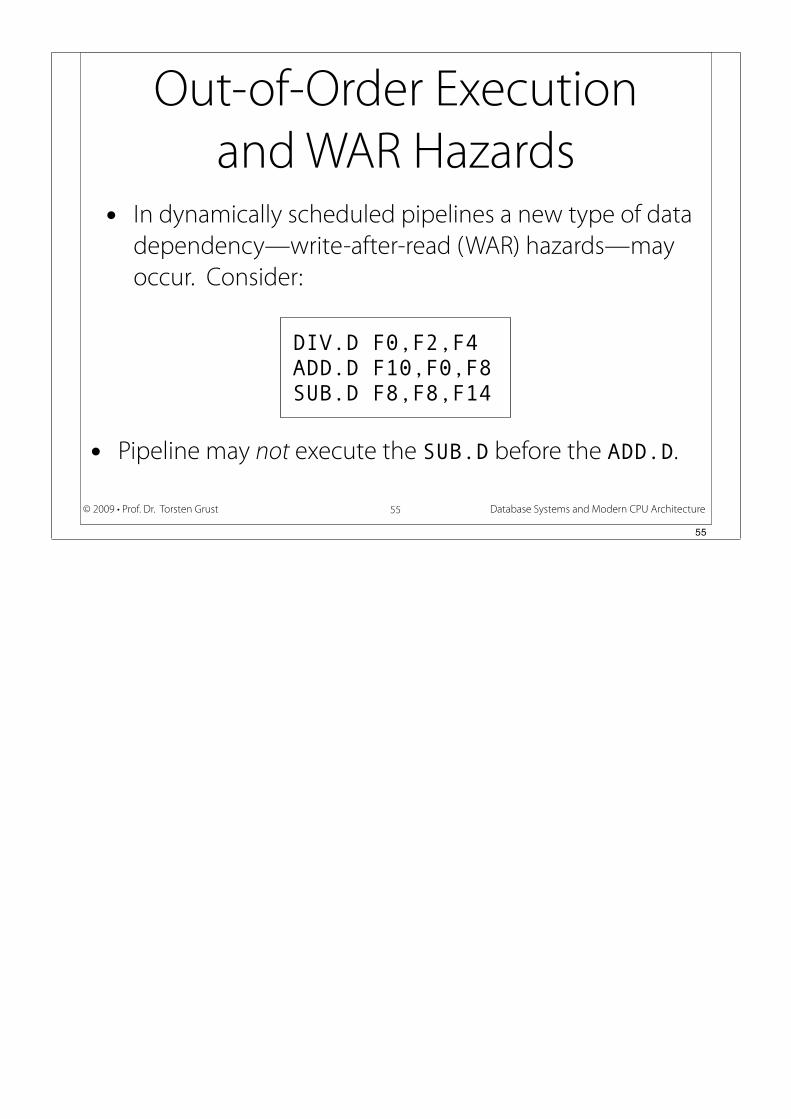
Out-of-Order Execution
and WAR Hazards
• In dynamically scheduled pipelines a new type of data
dependency—write-after-read (WAR) hazards—may
occur. Consider:
55
DIV.D F0,F2,F4
ADD.D F10,F0,F8
SUB.D F8,F8,F14
• Pipeline may not execute the SUB.D before the ADD.D.
55