Embed Size (px)
Citation preview

1
CHAPTER 2
LENS AND MIRROR CALCULATIONS
2.1 Introduction
The equation that relates object distance p, image distance q and focal length f is
.111
fqp=+ 2.1.1
Or is it? Should that not be a minus sign on the left hand side? Or should it be a plus
sign for mirrors and minus for lenses? (“More for a Mirror; Less for a Lens.”?)
As all who have ever tried lens and mirror calculations know, the biggest difficulty we
have to face is that of the dreaded sign conventions. It seems that no two professors or
teachers or books use the same convention. No sooner have we mastered one than we
encounter a professor who insists upon another. Each professor thinks that his is far
superior to anyone else’s, or is even seemingly unaware that there could be any
convention other than his own. We rapidly become discouraged. Indeed, when we try to
use equation 2.1.1 there is just one chance in eight that we choose the correct sign for all
three symbols. In fact the situation is even worse than that. You might choose the signs
correctly for all the symbols and get the right answer, −15 cm, according to your own
convention, yet your professor, who uses a different convention, marks it wrong. You
might be perfectly clear in your own mind that, since the image is a virtual image, the
answer must be minus fifteen. But your professor may interpret the minus sign as
meaning that the image is to the left of the lens, or on the opposite side of the lens from
the object, or is inverted, and he consequently marks it wrong.
Truly, of course, an answer “−15 cm” means nothing unless we are all certain as to
exactly what it meant by the minus sign. I therefore suggest that you do not leave the
“answer” is this ambiguous form. If you are asked where the image is and what is its
magnification, be very explicit and make it clear, in words (not just by plus or minus
signs) whether the image
1. is on the same side of the lens as the object is, or on the opposite side;
2. is real or virtual;
3. is erect or inverted;
4. is magnified or diminished.
In this chapter I shall, needless to say, introduce my own sign convention, and needless to
say my own convention is vastly superior to anyone else’s and quite different from any
that you may already be used to or that your own teacher uses, or that you have ever seen
in any book.. Worse, I am not going to make use of equation 2.1.1 at all. Instead, I am
going to use a technique referred to as the convergence method. At first, you are not

2
going to like it at all, and you may give up impatiently after just a few minutes. I hope,
however, that you will persist. Let us look, for example, at the following problem:
The three lenses all have different refractive indices, all radii of curvature are different,
the whole thing is immersed in water, the last surface is a mirror, and the object is a
virtual object. Perhaps you are asked to find the image. Or you may be told where the
image is and asked to find one of the radii of curvature, or one of the refractive indices.
At present, this looks like a hopelessly difficult problem to be avoided before all others in
an examination. There is scarcely any chance of getting the right answer.
However, I now assert that, if you take a few minutes to understand the convergence
method, you will be limited in your ability to solve problems like these, correctly, solely
by the speed at which you can write. As soon as you see the problem you will
immediately and confidently know how to do it. You just have to make sure that you
know where to find the 1/x button on your calculator.
2.2 Limitations
Before describing the convergence method, I would say a few words about image
formation – words that are equally valid whether you choose to use the convergence
method or to stick to conventional equations such as equation 2.1.1.
We are assuming that a lens or mirror will form a point image of a point object, and that a
parallel beam entering a lens will come to a point focus. You are probably aware – even
if unfamiliar with all the fine details – that this is not exactly so, and you will be aware
that if the diameter of a lens or mirror is comparable to its focal length or to the object or
image distance, light will not come to a focus at a point, but the image will suffer from
spherical aberration. Also, if the angular size of the object or image is large, so that light
enters or leaves a lens or mirror at a large angle, additional aberrations such as coma and
astigmatism appear. (It is not always realised that both spherical aberration and
FIGURE II.1

3
astigmatism also occur with refraction at a plane interface; neither are phenomena
associated solely with curved refractive interfaces or curved reflective surfaces.)
Although angles in this chapter are assumed to be small, I shall rarely draw them as
small, because to do so would make for very cramped drawings.
In this chapter, I am going to ignore lens and mirror aberrations. I may possibly prepare
a separate chapter on lens and mirror aberrations sometime, but that is not the topic of the
present chapter. Thus, in this chapter, I am going to assume that all angles are small.
How small depends on how large an aberration we are prepared to tolerate. Generally it
means that I shall be satisfied with the approximation sin x = tan x = x. This
approximation is known as the paraxial approximation. It means that none of the light
rays make very large angles with the axis of the optical system.
You will also be aware that the refractive index varies with wavelength, and as a result
lenses are affected by chromatic aberration. This, too, I shall ignore, except for a brief
foray in section 2.9, and if I say that the refractive index of a lens (or rather of the glass of
which it is made) is 1.5, I am referring to a particular wavelength or colour.
Initially, I shall also make the approximation that lenses are thin. That is to say, I assume
that I can neglect the thickness of the lens compared with its focal length or with the
object or image distance. However, in section 2.11, I shall relax this restriction, and I
shall deal with “thick” lenses.
2.3 Real and Virtual
Most people have no trouble understanding what a real object is or the distinction
between a real image and a virtual image. A virtual object, however, may take one by
surprise – so let’s look at all of them here.
Figure II.2 shows a lens forming a real image of a real object, and I think it requires little
explanation. Light diverges from a real object and it converges to a real image. Real
photons of light depart from a real object, and real photons of light arrive at a real image.
* * O I
FIGURE II.2

4
Figure II.3 shows a lens forming a virtual image of a real object. As before, light
diverges from the real object, but no light converges to a real image. After refraction
through the lens, the light is diverging from a point where the photons have never visited.
The light is diverging from a virtual image.
Whereas you can project a real image on to a piece of card or a photographic film, you
cannot do this with a virtual image. The reason that you can see a real image with your
eye is that the additional optics of your eye bends the diverging light from the virtual
image and makes it converge on to a real image on your retina.
FIGURE 11.3
* * O I
FIGURE II.4
O *
I *

5
Figure II.4 illustrates what is meant by a virtual object. Light is coming from the left –
perhaps from a big lens beyond the left hand edge of the paper (or your computer screen).
It is converging to the point O, and, if the concave lens had not got in the way, it would
have formed a real image at O. However, as far as the concave lens of figure II.3 is
concerned, the point O to which the light was converging before it reached the lens is a
virtual object. No photons reach that point. The lens bends the light, which eventually
comes to a focus at a real image, I.
You will see that light converges to a real image or to a virtual object, and light diverges
from a real object or from a virtual image.
This is not a sign “convention”; it is just a statement of fact, or an explanation of what
are meant by “real object”, virtual object”, “real image” or “virtual image”.
2.4 Convergence
1.00 1.50 1.33
20 cm 40 cm
O I
FIGURE II.5
6
Figure II.5 shows a lens made of glass of refractive index 1.50. To the left of the lens is
air (refractive index 1.00). To the right of the lens is water (refractive index 1.33). A
converging beam of light is incident upon the lens directed toward a virtual object O that
is 60 cm from the lens. After refraction through the lens, the light converges to a real
image I that is 20 cm from the lens. I am not at this stage going to ask you to calculate
the radii of curvature of the lens. (You can’t – you need one more item of information.)
I just want to use this diagram to define what I mean by convergence.
The convergence of the light at the moment when it is incident upon the lens is called the
initial convergence C1, and it is defined as follows:
Initial convergence .distance Object
index Refractive = 2.4.1
The convergence of the light at the moment when it leaves the lens is called the final
convergence C2, and it is defined as follows:
Final convergence .distance ageIm
index Refractive = 2.4.2
Sign convention: Converging light has positive convergence;
Diverging light has negative convergence.
In our example: Initial convergence = + .cm01667.060
00.1 1−+=
Final convergence = + .cm06650.020
33.1 1−+=
Notice that, before the light enters the lens, it is in a medium of refractive index 1.00.
Thus the relevant refractive index is 1.00, even though the virtual object is in the water.
2.5 Power
It will be evident that the function of a lens is to change the convergence of a beam of
light. Indeed the difference between the initial and final convergence is called the power
P of the lens, or of a refracting interface, or of a reflecting mirror. Thus, here is the only
equation you need to know in geometric optics. (Well, maybe not quite true.)
Final convergence = initial convergence plus power,
or C2 = C1 + P. 2.5.1

7
In order to solve a question in geometric optics, then, it is necessary to know the power of
the optical system.
There are three basic optical elements for which we need to know the power, namely a
lens, a refracting interface, and a reflecting surface.
I am now going to tell you, without proof, what the powers of these elements are. I shall
supply proofs later. For the moment, I want us to become used to using the formulas,
accurately and at speed.
1. The power of a lens of focal length f is
.1
fP = 2.5.2
Note that by the focal length of a lens I mean the focal length of the lens when it is in a
vacuum, or, what amounts to almost the same thing, when it is in air.
Sign convention: The focal length of a converging lens is positive;
The focal length of a diverging lens is negative.
2. The power of a refracting interface, of radius of curvature r, separating media
of refractive indices n1 and n2, is
.12
r
nnP
−= 2.5.3
Sign convention:
The radius of curvature of a convex surface or interface is positive;
The radius of curvature of a concave surface or interface is negative.
3. The power of a reflecting spherical surface of radius of curvature r immersed
in a medium of refractive index n is
.2
r
nP −= 2.5.4
Power can be expressed in cm−1
or in m−1
. In this connection a m−1
is sometimes
called a diopter. Thus a lens of focal length 5 cm has a power of 20 diopters.

8
2.6 Magnification
Magnification is, of course, defined as
Magnification .heightObject
heightageIm= 2.6.1
Strictly speaking, this is the linear transverse (or lateral) magnification. There are other
“sorts” of magnification, such as angular magnification and longitudinal magnification,
but we shan’t deal with these just yet, and the term “magnification” will be assumed to
mean the lateral linear magnification.
I now assert without proof, (but I shall prove later) that the magnification can be
calculated from
Magnification .
2
1
C
C
econvergencFinal
econvergencInitial== 2.6.2
Sign convention:
If the magnification is positive, the image is erect;
If the magnification is negative, the image is inverted.
2.7 Examples
1. A real object is 15 cm from a converging lens of focal length 25 cm. Where is
the image? Describe it.
Light diverges from a real object, so the initial convergence is negative. C1 = −1/15
cm−1
. The power of the converging lens is P = + 1/25 cm−1
. The final convergence is
.cm75
2
25
1
15
1 1
2
−−=+−=C
The image is 37.5 cm from the lens. Light is diverging after it leaves the lens. The
image is on the same side of the lens as the object is. It is a virtual image. The
magnification is C1/C2 = +2.5. The image is erect and magnified in size.
2. The faces of a biconvex lens have radii of curvature 20 cm and 30 cm, and the
refractive index of the glass is 1.5. What is the focal length of the lens?
Refer to figure II.6.

9
The initial convergence is zero. The final convergence will be 1/f. The power of the first
surface is 20
0.15.1
+
−cm
−1. The power of the second surface is
30
5.10.1
−
−cm
−1. Note
that the radius of curvature of the second surface, when encountered by the light, is
negative.
Therefore: .30
5.10.1
20
0.15.11
−
−+
+
−=
f
â f = 24 cm.
The lens is a converging lens.
3. What is the focal length of this lens, in which I have marked the radii of
curvature in cm and the refractive indices?
The power, which is the reciprocal of the focal length, is the sum of the powers of the
three interfaces:
.cm400.040
6.10.1
18
5.16.1
20
0.15.11 1−+=−
+−
−+
−= &
f â f = +225.0 cm.
? 1.5
20 30
1.0 1.0
FIGURE II.6
18
40
1.5
1.6
20
10
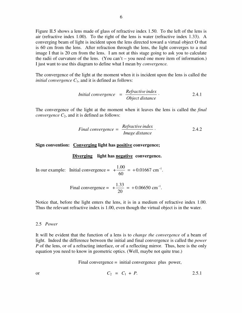
4. Let’s now go straight to the impossibly difficult problem of section 2.1
I have marked in the several refractive indices, and, in italics, the radii of curvature and
the distance of the virtual object, in cm. Remember that, notwithstanding the drawing,
we are assuming that all lenses are thin – that is to say that their thicknesses are
negligible compared with other distances.
The system is immersed in water, so the initial convergence is +1.33/50. We are going to
find the final convergence. To the initial convergence we are going to add, successively,
the powers of the first three refracting interfaces, then the reflecting surface, and then the
three refracting surfaces again on the way out. Watch for the refractive indices and the
signs of the radii of curvature in each term. The calculation goes like this – as fast as you
can write:
Final convergence =
.cm35
50.133.1
38
00.150.1
28
60.100.1
26
60.12
28
00.160.1
38
50.100.1
35
33.150.1
50
33.1
1−
−
−+
+
−+
+
−+
+
×−+
−
−+
−
−+
−++
You can almost double the speed when you realize that the power of a refracting interface
is the same whichever way you go (from left to right or from right to left).
We obtain: Final convergence = −0.103304 cm−1
.
Final convergence is refractive index divided by image distance, so the distance of the
image from the lens (remember that it’s a thin lens, so don’t ask which part of the lens) is
1.33 ÷ 0.103304, or 12.9 cm.
1.00
1.50
35 38 26
50
1.33 1.60
28
FIGURE II.7
11
The light is diverging after it leaves the lens. It is on the same side of the lens as the
virtual object is. It is a virtual image. The magnification is initial convergence ÷ final
convergence and is therefore −0.257. The image is inverted and diminished in size.
This example perhaps shows the greatest power (pun not intended) of the convergence
method – i.e. in dealing with many optical elements one after the other. The is no need
for convoluted arguments such as “the real image formed by the first element acts as a
virtual object for the second element, and then...”.
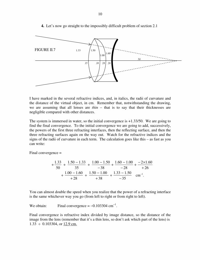
5. Three observations are performed on a lens in order to determine the radii of
curvature of its two surfaces and the refractive index of its glass.
i.) A real object is placed 40 cm to the left of the lens, and a real image is
formed 300 cm to the right.
The question doesn’t tell us what sort of a lens it is. Let’s suppose that it is
biconvex; we’ll soon find out if it isn’t.
The first experiment tells us:
.11
40
1
300
1
21 r
n
r
n
−
−+
−+−=
+
That is:
.cm3028.011
)1( 1
21
−=
+− &
rrn 2.7.1
ii.) The lens is floated on the surface of mercury, r1-side up. A real object is
placed 60 cm above it, and a real image is formed 50 cm above it.
n
r1 r2
* * I
O
40 300
FIGURE II.8

12
The second experiment tells us:
.121
60
1
50
1
121 r
n
r
n
r
n
−
−+
−
−+
−+−=+
That is: .3018.01
21
&=+−
r
n
r
n 2.7.2
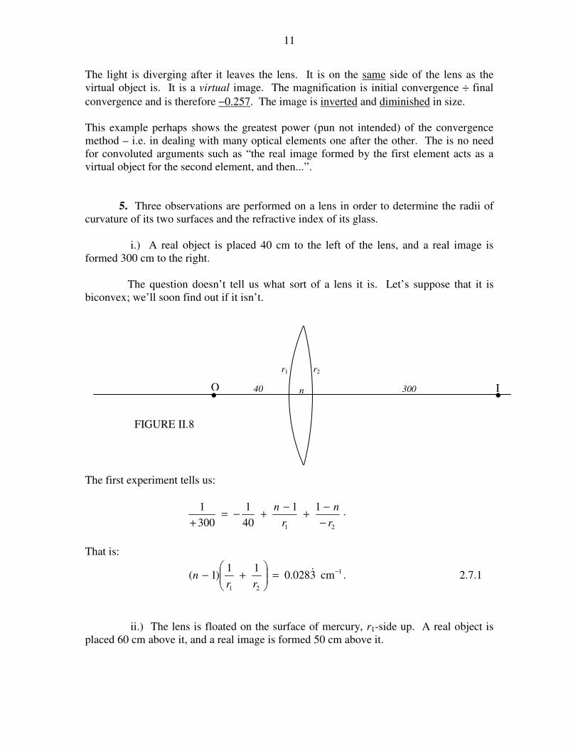
iii.) The lens is floated on the surface of mercury, r2-side up. A real
object is placed 60 cm above it, and a real image is formed 6 cm above it. (Figure II.10.)
It is necessary to remind ourselves that, the drawing notwithstanding, the lens is thin and
all angles are small.
The third experiment tells us:
.121
60
1
6
1
212 r
n
r
n
r
n
−
−+
−
−+
−+−=+
That is: .6091.01
12
&=+−
r
n
r
n 2.7.3
Thus we have three nonlinear equations to solve for the three unknowns. Three nonlinear
equations have been known to make grown men tremble in their shoes, but fortunately
these three are trivial to solve. It might help to let s = 1/r1 and t = r2, when the equations
become
*
*
r2
r1
50
10
O
I
n
FIGURE II.9

13
.3028.0))(1( &=+− tsn 2.7.4
.3018.0)1( &=+− ntsn 2.7.5
.6091.0)1( &=+− nstn 2.7.6
One soon arrives at: n = 1.53, r1 = 15.8 cm, r2 = −100.0 cm.
Our assumption that the lens is biconvex was wrong. The second surface is the other way
round, and the lens is a meniscus converging lens.
Exercise. A converging lens forms a real image of a real object. Show that the least
distance between real object and real image is 4f, and that the magnification is then −1.
Remember this when you are trying to show slides in your living room, and you can’t
seem to focus the projector on the screen.
Exercise. A screen is at a fixed distance from a real object. A converging lens is placed
between object and screen so as to throw a magnified inverted real image on the screen.
The lens is then moved towards the screen, and, after it has moved a distance d, it is seen
*
*
54
O
I
n
r1
r2 6
FIGURE II.10
14
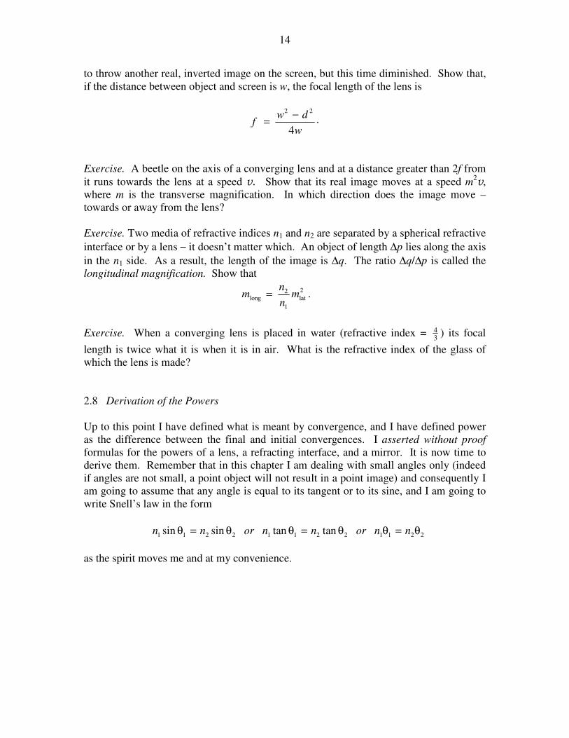
to throw another real, inverted image on the screen, but this time diminished. Show that,
if the distance between object and screen is w, the focal length of the lens is
.4
22
w
dwf
−=
Exercise. A beetle on the axis of a converging lens and at a distance greater than 2f from
it runs towards the lens at a speed v. Show that its real image moves at a speed m2v,
where m is the transverse magnification. In which direction does the image move –
towards or away from the lens?
Exercise. Two media of refractive indices n1 and n2 are separated by a spherical refractive
interface or by a lens – it doesn’t matter which. An object of length ∆p lies along the axis
in the n1 side. As a result, the length of the image is ∆q. The ratio ∆q/∆p is called the
longitudinal magnification. Show that
.2
lat
1
2long m
n
nm =
Exercise. When a converging lens is placed in water (refractive index = 34 ) its focal
length is twice what it is when it is in air. What is the refractive index of the glass of
which the lens is made?
2.8 Derivation of the Powers
Up to this point I have defined what is meant by convergence, and I have defined power
as the difference between the final and initial convergences. I asserted without proof
formulas for the powers of a lens, a refracting interface, and a mirror. It is now time to
derive them. Remember that in this chapter I am dealing with small angles only (indeed
if angles are not small, a point object will not result in a point image) and consequently I
am going to assume that any angle is equal to its tangent or to its sine, and I am going to
write Snell’s law in the form
221122112211 tantansinsin θ=θθ=θθ=θ nnornnornn
as the spirit moves me and at my convenience.

15
2.8.1 Power of a Lens
I have drawn two rays emanating from the tip of the object. One is parallel to the axis;
after refraction it passes through the focus. The other goes through the centre (“pole”) of
the lens; since the lens is “thin”, this ray is neither deviated not displaced. The two rays
cross at the tip of the image. From two obvious pair of similar triangles, we see that
.'
f
fq
p
q
h
h −== 2.8.1
From this we immediately obtain
.111
fpq+−= 2.8.2
Since the initial and final convergences are −1/p and 1/q, it follows that the power is 1/f.
You might want to draw the cases where the real object is at a distance less than 2f from
the lens (and hence forms a virtual image) or for a virtual object, or the corresponding
situations for a diverging lens. You will reach the same conclusion in each case.
2.8.2 Power of a Refracting Interface
h
h' O
I
p q − f f * F
FIGURE II.11
α γ
C p q − r r
h
O I
n1 n2
β
θ1
θ2
FIGURE II.12

16
Figure II.12 shows a refracting interface of radius of curvature r separating media of
indices n1 and n2. I show a real object at O, a real image at I and the centre of curvature
at C. Remember that angles are small and the “lens” is thin. We see that
.rqph γ=β=α= By Euclid, ,and 21 β−γ=θγ+α=θ and by Snell,
.2211 θ=θ nn From these, we obtain
.1212
r
nn
p
n
q
n −+−= 2.8.3
Thus the power is .12
r
nn − The reader should try this for other situations (virtual
object, virtual image, concave interface, and so on) to see that you always get the same
result.
2.8.3 Power of a Mirror
In figure II.13 shows a reflecting surface of radius of curvature r submerged in a medium
of index n. I show a real object at O, a virtual image at I and the centre of curvature at C.
We see that .rqph γ=β=α= By Euclid, .2and β+α=θγ+α=θ Remember
again that all angles are supposed to be small (even β!), in spite of the drawing. From
these we obtain
.211
rpq+= 2.8.4
On multiplying this by −n, we find that the power is −2n/r. Again the reader should try
this for other situations, such a concave mirror, or a real image, and so on. The same
result will always be obtained.
O
α
C p q r − q q
h
p
h '=
β
γ
I
θ
θ
FIGURE 11.13
h
17
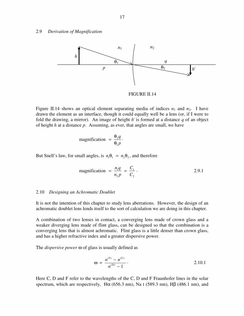
2.9 Derivation of Magnification
Figure II.14 shows an optical element separating media of indices n1 and n2. I have
drawn the element as an interface, though it could equally well be a lens (or, if I were to
fold the drawing, a mirror). An image of height h' is formed at a distance q of an object
of height h at a distance p. Assuming, as ever, that angles are small, we have
magnification .
1
2
p
q
θ
θ=
But Snell’s law, for small angles, is 2211 θ=θ nn , and therefore
magnification .
2
1
2
1
C
C
pn
qn== 2.9.1
2.10 Designing an Achromatic Doublet
It is not the intention of this chapter to study lens aberrations. However, the design of an
achromatic doublet lens lends itself to the sort of calculation we are doing in this chapter.
A combination of two lenses in contact, a converging lens made of crown glass and a
weaker diverging lens made of flint glass, can be designed so that the combination is a
converging lens that is almost achromatic. Flint glass is a little denser than crown glass,
and has a higher refractive index and a greater dispersive power.
The dispersive power ω of glass is usually defined as
.1)D(
)C()F(
−
−=ω
n
nn 2.10.1
Here C, D and F refer to the wavelengths of the C, D and F Fraunhofer lines in the solar
spectrum, which are respectively, Hα (656.3 nm), Na I (589.3 nm), Hβ (486.1 nm), and
n1 n2
p
q
h'
h
θ1
θ2
FIGURE II.14

18
which may be loosely referred to as “red”, “yellow” and “blue”. A typical value for a
crown glass would be about 0.016, and a typical value for a flint glass would be about
0.028.
An achromatic doublet is typically made of a positive crown glass lens whose power is
positive but which decreases with increasing wavelength (i.e. toward the red), cemented
to a weaker flint glass lens whose power is negative and also decreases (in magnitude)
with increasing wavelength. The sum of the two powers is positive, and varies little with
wavelength, going through a shallow minimum. Typically, in designing an achromatic
doublet, there will be two requirements to be satisfied: 1. The power or focal length in
yellow will be specified, and 2. You would like the power in red to be the same as the
power in blue, and to vary little in between.
Consider the doublet illustrated in figure II.15, constructed of a biconvex crown lens and
a biconcave flint lens.
I have indicated the indices and the radii of curvature. The power (reciprocal of the focal
length) of the first lens by itself is
,11
)1( 11
+−=
banP 2.10.2
and the power of the second lens is
.11
)1( 22
+−−=
cbnP 2.10.3
I shall write these for short, in obvious notation, as
.)1(,)1( 222111 −−=−= nkPnkP 2.10.4a,b
But we need equations like these for each of the three wavelengths, thus:
,)1(,)1( )C(
22
)C(
2
)C(
11
)C(
1 −−=−= nkPnkP 2.10.5a,b
,)1(,)1( )D(
22
)D(
2
)D(
11
)D(
1 −−=−= nkPnkP 2.10.6a,b
n1
n2
a b c
FIGURE II.15

19
.)1(,)1( )F(
22
)F(
2
)F(
11
)F(
1 −−=−= nkPnkP 2.10.7a,b
Now we want to satisfy two conditions. One is that the total power be specified:
. )D()D(
2
)D(
1 PPP =+ 2.10.8
The other is that the total power in the red is to equal the total power in the blue, and I
now make use of equations 2.10.5 and 2.10.7:
.)1()1()1()1( )F(
22
)F(
11
)C(
22
)C(
11 −−−=−−− nknknknk 2.10.9
On rearrangement, this becomes
.)()( )C(
2
)F(
22
)C(
1
)F(
11 nnknnk −=− 2.10.10
Now, making use of equations 2.10.1 and 2.10.6, we obtain the condition that the powers
will be the same in red and blue:
.02211 =ω+ω PP 2.10.11
Equations 2.10.8 and 2.10.11 together satisfy our two conditions and tell us what the
powers of the two lenses must be to satisfy both of them.
For example, suppose that we want the focal length in yellow to be 16 cm
)cm0625.0( 1)D( −=P and that the dispersive powers are 0.016 and 0.028. Equations
2.10.8 and 2.10.11 then tell us that we must have 1)D(
2
1)D(
1 cm308.0andcm31458.0 −− −== && PP . (f1 = 6.86 cm and f2 = −12.0 cm.)
If we want to make the first lens equibiconvex, so that a = b, and if n1 = 1.5, equation
2.10.2 tells us that a = 6.86 cm. If n2 = 1.6, equation 2.10.3 then tells us that c = −144 cm.
That c is negative tells us that our assumption that the flint lens was concave to the right
was wrong; it is convex to the right.
Exercise. Suppose that, instead of making the crown lens equibiconvex, you elect to
make the last surface flat – i.e. c = ∞. What, then, must a and b be?
Answers. a = 6.55 cm, b = 7.20 cm.
20
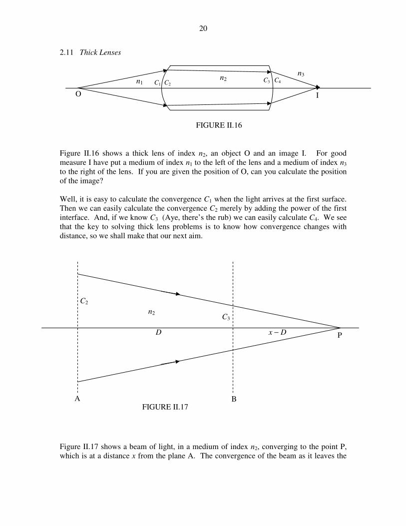
2.11 Thick Lenses
Figure II.16 shows a thick lens of index n2, an object O and an image I. For good
measure I have put a medium of index n1 to the left of the lens and a medium of index n3
to the right of the lens. If you are given the position of O, can you calculate the position
of the image?
Well, it is easy to calculate the convergence C1 when the light arrives at the first surface.
Then we can easily calculate the convergence C2 merely by adding the power of the first
interface. And, if we know C3 (Aye, there’s the rub) we can easily calculate C4. We see
that the key to solving thick lens problems is to know how convergence changes with
distance, so we shall make that our next aim.
Figure II.17 shows a beam of light, in a medium of index n2, converging to the point P,
which is at a distance x from the plane A. The convergence of the beam as it leaves the
n1 n2
O I
C1 C2 C3 C4
n3
FIGURE II.16
FIGURE II.17
C2
C3
n2
D
A B
P x − D

21
plane A is ./22 xnC = When it arrives at the plane B, which is at a distance D from the
plane A, its convergence is .)/(23 DxnC −= When we eliminate x, we obtain
22
223
DCn
CnC
−= 2.11.1
for the formula that tells us how convergence changes with distance.
Let us now return to the problem of figure II.16. Let’s suppose that the radii of curvature
of the first and second faces are 15 and 25 cm respectively, and the distance between the
faces is 50 cm. The refractive index of the glass is n2 = 1.60. We’ll suppose that there is
water (n1 = 1.33) to the left of the lens, and, to the right of the lens there is some liquid
with refractive index 1.42. The object is 30 cm to the left of the first face. Where is the
image?
The calculation goes as follows:
.cm333044.030
33.1 1
1
−−=−=C
.cm333026.015
33.160.1 1
12
−−=+
−+= CC
.cm446014.05060.1
60.1 1
2
23
−−=×−
×=
C
CC
Notice that the light is diverging by the time that it reaches the second face.
.cm246007.025
60.142.1 1
34
−−=−
−+= CC
The light is still diverging, so the image is virtual. The distance of the image from the
second face is 1.42 ÷ 0.007 246 = 196 cm, and it is to the left of the second face.
The magnification of a thick lens is easily found. The magnification produced by the first
face is, as usual, C1/C2, and then there is a further magnification of C3/C4 produced by the
second face. Thus the overall magnification is ,
42
31
CC
CC which is this case is +3.356. The
image is magnified in size and it is erect.
This method for thick lenses can also be used for separated lenses and mirrors. Here’s
one: Figure II.18 shows a thin lens separated from a mirror, and an object 14 cm from
the lens. Where is the image?

22
.cm420071.014/1 1
1
−−=−=C
.cm031429.025/1 1
12
−−=+= CC
.cm924013.0401
1
2
23
−−=×−
=C
CC
.cm743052.030
2 1
44
−+=−
−+= CC
The image is real. It is 18.96 cm to the left of the mirror. The magnification is −0.60.
The image is inverted and diminished.
Of course those who set examinations can think of all sorts of unpleasant questions. For
example, we might have a thick lens and an object, but, instead of being asked to find the
image, we may be told the image distance and asked to find the refractive index, or the
thickness, or one of the radii. Or, even worse, we might not be told the image distance,
but we might be told its magnification and whether it is real or virtual, or erect or
inverted, and asked to find something else. There are endless possibilities! Here’s one.
* O
14 cm
r = 30 cm
40 cm
f = 25 cm
FIGURE II.18
16 30
5
n?

23
The lens shown has radii of curvature 16 and 30 cm, and is 5 cm thick. An object is 36
cm to the left of the 16 cm face. Its image is 50 cm to the right of the 30 cm surface.
Show that the refractive index is the positive solution of
.052024171845 2 =−− nn
Here’s another one:
The lens shown is 4 cm thick and the refractive index is 1.6. The radius of curvature of
the first face is 15 cm. An object is 32 cm to the left of the 15 cm face. Its image is real,
inverted and magnified by 22. Determine the radius of curvature of the second face.
Hints. The image is real. Which side of the lens is it? You can easily calculate C1 , C2
and C3, so you should be able to get C4 from the magnification. The answer, by the way,
is 80.1 cm – but is it convex to the right, as shown, or is it concave to the right?
One more:
The two lenses are made of a very light solid whose refractive index is only 1.3. (I’m not
sure if there is such a stuff!) and they are immersed in a liquid of index 1.4. That means
that the convex lens is diverging. The second surface of the second lens is a reflecting
mirror. I have indicated the radii of curvature, and the lenses are 40 cm apart. Parallel
light comes from the left. Where does it come to a focus?
15 r?
4
1.6 FIGURE II.19
15 20 25 30
40
1.4 1.4 1.4
1.3
1.3
FIGURE II.20

24
The initial convergence C1 = 0. I’ll calculate the convergence after the light arrives at or
leaves each surface or interface. I hope the notation will be clear. All convergences are
in cm−1
.
.600.015
4.13.102
&−=+
−+=C
.6011.020
3.14.1600.03
&& −=−
−+−=C
.00875.0404.1
4.1
3
34 −=
−=
CC
.00475.025
4.13.100875.05 −=
−
−+−=C
.609141.030
3.1200475.06
&−=×−
+−=C
.608741.025
3.14.1609141.07
&& −=+
−+−=C
.65192993024.0404.1
4.1
7
78 −=
−=
C
CC
.65192993029.020
4.13.189 −=
−
−+= CC
.31859659036.015
3.14.1910 −=
−
−+= CC
Finally, x
C4.1
10 = , so x = −38.188 908 15
−=
577
22035 cm.
That is, the focus is 38.2 cm to the right of the convex lens, or 1.8 cm to the left of the
concave lens.
Another one: Compose a problem in which a student is given the focal length of two
lenses, and the positions of object and image, and the student is asked to calculate the
distance between the lenses.

25
2.12 Principal Planes
Consider a thick lens, or a system of two separated lenses. In figure II.21, F1 is the
first focal point and H1 is the first principal plane. In figure II.22, F2 is the second focal
point and H2 is the second principal plane.
H1
F1
F1
H1
FIGURE II.21

26
I refer now to the second part of figure II.22, and I suppose that the focal lengths of the
two lenses are f1 and f2, and the distance between them is D. I now invite the reader to
calculate the distances x2 and y2. The distance x2 can be calculated by consideration of
some similar triangles (which the reader will have to add to the drawing), and the
distance y2 can be calculated by calculating the convergences 4321 ,,, CCCC in the manner
which is by now familiar. You should get
Dff
Dfx
−+=
21
22 2.12.1
F2
H2
H2
F2
FIGURE II.22
x2
f1 f2
D
y2

27
and .)(
21
122
Dff
Dffy
−+
−= 2.12.2
I further invite the reader to imagine that the two lenses are to be replaced by a single
lens situated in the plane H2 so as to bring the light to the same focus F2 as was obtained
by the two original lenses. The question is: what must be the focal length f of this single
lens? The answer is obviously 22 yx + , which comes to
.21
21
Dff
fff
−+= 2.12.3
The eyepiece of an optical instrument such as a telescope or a microscope is generally a
combination of two (or more) lenses, called the field lens and the eye lens. They are
generally arranged so that the distance between the two is equal to half the sum of the
focal lengths of the two lenses. We shall now see that this arrangement, with two lenses
made of the same glass, is relatively free from chromatic aberration.
Let us remind ourselves that the power of a lens in air is given by
+−==
21
11)1(
1
rrn
fP 2.12.4
Here r1 and r2 are the radii of curvature of the two surfaces, and n is the refractive index
of the glass. For short, I am going to write equation 2.12.4 as
Sf
P µ==1
, 2.12.5
where 1−=µ n and .11
21
+=
rrS That being so, equation 2.12.3 can be written
212
21 )( SDSSSP µ−+µ= 2.12.6
This equation shows how the position of the focus F2 varies with colour. In particular,
2121 2 SDSSSd
dPµ−+=
µ, 2.12.7
which shows that the position of F2 doesn’t vary with colour provided that the distance
between the lenses is

28
21
21
2 SS
SSD
µ
+= . 2.12.8
On going back to equation 2.12.5, we see that this translates to
).( 2121 ffD += 2.12.9
2.13 The Lazy Way
The convergence and power method has great advantages when you have a complex
systems of many lenses, mirrors and interfaces in succession. You just add the powers
one after the other. But I expect there are some readers who don’t want to be bothered
with all of that, and just want to do simple single-lens calculations with a simple formula
that they are accustomed to, in particular the well-known ,111
fqp=+ which is
appropriate for the “real is positive” sign convention – and they want to get the
calculation over with as soon as possible and with as little effort as possible. This section
is for them! I have drawn a simple diagram in figure II.23. It is not extremely accurate –
it is the best I can do with this infernal machine that I am sitting in front of. All you need
in order to draw a really good version of it is a sheet of graph paper. There are three
axes, labelled p, q and f. For any particular problem, to solve the above equation, all you
do is to lay the edge of a ruler across the figure. For example: p = 40 cm, f = 26 cm.
What is q? The dashed line gives the answer: q = 75 cm. Another example: p = 33 cm,
q = −60 cm. What is f? The dotted line gives the answer: f = 73 cm.
This diagram can also be used for resistors in parallel, capacitors in series, synodic and
sidereal periods of planets...

29
100
100 100
80
80 80
60
60 60
40
40 40
20
20 20
−100 −100
−100
−80 −80
−80
−60 −60
−60
−40 −40
−40
−20 −20
−20
f q
FIGURE II.23
p

30
2.14 Exercises
1. An object is placed 90 cm to the left of a thin lens in air. The image is real and is
99 cm to the right of the lens.
However, if the medium to the right of the lens is water (refractive index 1.33), the image
is virtual and is 76 cm to the left of the lens.
And if the medium to the left of the lens is water (and to the right is air) the image is real
and 47 cm to the right of the lens.
Calculate the two radii of curvature and the refractive index of the glass.
2. An object is placed 100 cm to the left of the first surface (A) of a thick lens
(thickness = 10 cm) in air. The image is real and is 25 cm to the right of the second
surface (B).
However, if the medium to the right of the second surface (B) is water (refractive index
1.33), the image is real and 41 cm to the right of surface B.
And if the medium to the left of surface A is water (and to the right of B is air) the image
is real and 92 cm to the right of the lens.
Calculate the two radii of curvature and the refractive index of the glass.
Neither of these two problems is likely to turn up in a practical situation – but they are
very good practice for difficult lens problems!
Solutions on the next page – but no peeking until you have tried them!

31
Solutions.
1.
First:
.11
90
1
99
1
21 r
n
r
n −+
−+−= 2.14.1
Second:
.33.11
90
1
76
33.1
21 r
n
r
n −+
−+−=− 2.14.2
(You might be tempted to think that the left hand side of this equation should be .76
1−
Make sure that you understand why this is wrong.)
Third:
.133.1
90
33.1
47
1
21 r
n
r
n −+
−+−= 2.14.3
• O
90 • I
99
n
r1 r2
1 1
• O
90 • I
76
n
r1 r2
1 1.33
• O
90 • I
47
n
r1 r2
1 1.33

32
The physics is now finished. All that has to be done is to solve the three equations for the
three unknowns. I would start by letting .,, 21 nzryrx === The equations then
become:
,021212121.0)( =+−− yxyxz 2.14.4
006388889.033.1)( −=+−− yxyxz 2.14.5
and .036054374.033.1)( =+−− yxyxz 2.14.6
These are easy to solve:
.54864.1,083639.0,044977.0 +=−=−= zyx
Thus
.5549.1,cm96.11,cm23.22 21 =−=−= nrr
The lens is a positive meniscus lens (i.e. thicker in the middle), both surfaces being
convex to the right. It looks like this:

33
2. First:
100
11 −=C 2.14.7
1
1
1
2100
1001001
100
1
r
rn
r
nC
−−=
−+−= 2.14.8
1000100010100
100100
10 11
1
2
2
23
+−+
−−=
−=
nrnr
nrnn
Cn
nCC 2.14.9
25
11
1000100010100
100100
211
1
2
4 =−
++−+
−−=
r
n
nrnr
nrnnC 2.14.10
Second:
100
11 −=C 2.14.11
1
1
1
2100
1001001
100
1
r
rn
r
nC
−−=
−+−= 2.14.12
1000100010100
100100
10 11
1
2
2
23
+−+
−−=
−=
nrnr
nrnn
Cn
nCC 2.14.13
41
33.133.1
1000100010100
100100
211
1
2
4 =−
++−+
−−=
r
n
nrnr
nrnnC 2.14.14
• O
100
1 1 n
10
• I
25 r2 r1
• O
100
n
10
• I
41 r2 r1
1.33 1

34
So far, we have obtained two complicated-looking equations (2.14.10 and 2.14.14) in the
three unknowns r1, r2 and n, and we are just about to embark on obtaining a third
equation from the third experiment, after which we shall have to face the unpleasant task
of solving the three equations. But look! – before we press on, we may discover that we
can already solve for r2 from equations 2.14.10 and 2.14.14. I make it
cm29161645.432 −=r 2.14.15
so that the second surface is concave to the left – i.e. it bulges towards the right. This
was an unexpected piece of good fortune! We can now move on to the third experiment.
Third:
100
33.11 −=C 2.14.16
1
1
1
2100
33.113310033.1
100
33.1
r
rn
r
nC
−−=
−+−= 2.14.17
133010003.13100
33.1133100
10 11
1
2
2
23
+−+
−−=
−=
nrnr
nrnn
Cn
nCC 2.14.18
92
11
133010003.13100
33.1133100
211
1
2
4 =−
++−+
−−=
r
n
nrnr
nrnnC 2.14.19
We can now solve equations 2.14.10 and 2.14.19, or 2.14.14 and 2.14.19 for r1 and n.
The very conscientious will want to solve them using 2.14.10 and 2.14.19 and then repeat
the solution using 2.14.14 and 2.14.19, and verify that they give the same answer, and
will then further verify that the correct solutions have been obtained by substitution in
each of the three equations in turn. Being slightly less conscientious, I am going to use
equations 2.14.10 and 2.14.19, and I shall then verify that the solutions obtained satisfy
equation 2.14.14.
I find it easier to solve equations in x and y rather than in r1 and n, so I am going to let
1rx = and y = n. Then, bearing in mind that we have already found that
,29161645.432 −=r equations 2.14.10 and 2.14.19 become, respectively, after a little
algebra and arithmetic,
• O
100
n
10
• I
92 r2 r1
1 1.33

35
cbyyxxy
xyyy+=
+−+
−−
1000100010100
100100 2
2.14.20
and ,1000100010100
100100 2
dbyayaxxy
axyayy+=
+−+
−− 2.14.21
where
52612781033.0
30046912062.0
30047912022.0
33.1
+=
+=
−=
+=
d
c
b
a
After a little more slightly tedious but routine algebra and arithmetic, these become
01111
22 =+++++ FyExDxyCByAxy 2.14.22
and ,02222
22 =+++++ FyExDxyCByAxy 2.14.23
where
.65544929.44
57364745.68
447295449.0
023431403.4
30047912.62
40905175.14
0473120629.0
257084062.7
70952087.77
730204291.2
2
2
2
2
1
1
1
1
−=
−=
−=
−=
−=
−=
−=
−=
=
=
F
E
D
C
F
E
D
C
B
A
Then we have to solve these two equations! These can be solved, for example, by the
method described in Section 1.9 of Chapter 1 of the notes on Celestial Mechanics. Since
I already have a computer program that does that, I used it and got x = 15.386908 and
.518865.1=y Thus the solution for the lens is
519.1cm65.43cm39.15 21 =−=+= nrr

36
The first surface is convex to the left, and the second surface is convex to the right. I.e.
the lens is “fat”, bulging in the middle.
As a check that our arithmetic is all right, we can verify that this solution also satisfies
equation 2.14.14. (It does!)
As a further check, the reader might now like to start with these numbers, and an object
distance of 100 cm, and see if it results in the three image distances given in the original
problem. (It does!)
Another way to solve equations 2.14.22 and 2.14.23 is to subtract the former from the
latter to obtain
,0=+++ dcybxaxy 2.14.24
.98260265.17
56945917.54
179825026.0
658653234.2
where
=
−=
=
=
d
c
b
a
You can then express x and a function of y and substitute into equation 2.14.22 (or into
2.14.23, or both as a check). You then have a single cubic equation in y, rather than two
simultaneous equations in x and y, as follows:
.0)()()( 111111
2
11
3 =−+−−++−−++− cDbFydCcDbEaFyAdcCBbaEyAcBa 2.14.25
Numerically, this is
.010294.614660950.774024164.4509799377.329 523 =×−−− −yyy 2.14.26
The only positive real root of this is y (= n) = 1.518864, which is the same as we
obtained before. The value of x (= r1) is then readily found, from equation 2.14.24, to be
15.3869 cm, as before.

37
More problems:
3. A converging lens has a focal length of 40 cm in air. What is its focal length when it
is immersed in water, of refractive index 1.333?
After a moment’s thought you will demand that you be told the refractive index of the
glass. After further thought, you will conclude that not only do you need to know the
refractive index of the glass, but you also need to know the shape (radii of curvature of
the surfaces) of the lens.
So, here’s the question properly set.
A biconvex lens is made of glass of refractive index 1.5. The radii of curvature of its
surfaces are 25 cm and 100 cm. What is its focal length in air? What would be its focal
length if immersed in water of refractive index 4/3? What would be its focal length if
immersed in carbon bisulphide of refractive index 5/3?
4. A lens has a focal length in air of 30 cm.
A block of glass with the same refractive index as the above lens has an air bubble
inside it of exactly the same size and shape of the above lens. What is the focal length of
this lens-shaped bubble?
You may be asking yourself if you need to know the shape of the lens, or the
refractive index of the glass. I’ll let you ponder.
5. A thin cemented doublet is made of two thin lenses cemented together, as shown in
the drawing below. The radii of curvature in cm are indicated in the drawing. The
refractive index of the left hand lens is n1, and that of the right hand lens is n2. The
combination results in an overall diverging doublet lens of focal length 127 cm.
50 40 22
n2
n1

38
As a result of a manufacturing error, the two types of glass are inadvertently exchanged,
and a doublet lens as shown below is made:
This combination results in an overall converging doublet lens of focal lens 72 cm.
Calculate the refractive indices of the two types of glass.
Here are my solutions to problems 3 to 5
3. The focal length in air is given by
,100
5.10.1
25
0.15.10
1
−
−+
−+=
f whence cm40=f
The focal length in water is given by
,10025
0 23
34
34
23
34
−
−+
−+=
f whence cm160=f
The focal length in CS2 is given by
,10025
0 23
35
35
23
35
−
−+
−+=
f whence cm200−=f
50 40 22
n1
n2

39
4.
Regardless of the shape of the lens, the focal length of the glass lens in air is given by
,11
)1(1
21lens
−−=
rrn
f
whereas the focal length of the bubble in glass is given by
.11
)1(21bubble
−−=
rrn
f
n
Thus cm30lensbubble nfnf −=×−=
5.
The focal lengths of the two doublets are related to the refractive indices by
50
1
2240
1
127
1 2121 nnnn −+
−
−+
−=−
and 50
1
2240
1
72
1 1212 nnnn −+
−
−+
−=
These equations can be rewritten
08031828819685 21 =+− nn
and 037413951296 21 =+− nn ,
with solutions 682.1521.1 21 == nn