Embed Size (px)
Citation preview

12
CHAPTER 2
INTRODUCTION TO GYRO-DEVICES
In the past few decades, there has been considerable effort to provide coherent, high-power
sources in the electromagnetic spectrum. Among many of these devices, gyrotrons have
proven to be efficient sources for r.f. generation at high power levels and up to very high
frequencies. The applications for gyrotrons range from microwave sources for industry,
medicine, high power radar, plasma diagnostics, material sintering, to r.f. driver for high
average power accelerators. The main motivation for the development of high frequency and
high power gyrotrons is that some applications such as magnetic heating require frequency
range above 100 GHz and with power in excess of several hundred kilowatts.
The advantage of high average power capability of gyrotrons is particularly evident in the
millimeter wave region. Conventional devices such as magnetrons and slow wave devices
such as klystrons, traveling wave tubes (TWTs) require structures smaller than the
wavelength, and are prone to overheating or breakdown at high frequencies. Thus in this part
of the electromagnetic spectrum they are severely limited in both power and efficiency.
Fast wave Gyro Devices are relatively new comers to the Microwave Family [36-48]. Also
known as “electron cyclotron masers”, “cyclotron resonance masers” or simply “gyrotrons”,
gyro devices take advantage of cyclotron resonance condition to transfer energy from an
electron beam to electromagnetic wave. The microwave frequency of the device and dc
magnetic field are related by the celebrated synchronism condition
zz
e
zze vkm
neBvkn
Where e is the electron cyclotron frequency, n is the harmonic number, e is the electronic
charge, B is the applied magnetic field strength, em is the electron rest mass, γ is the
relativistic factor. zk is the axial wave number and zv is the axial speed of the electron beam.
In most gyro-devices, Doppler–shift term zzvk is quite small, so the operating frequency is
equal to an integral multiple of cyclotron frequency.

13
2.1 Types of Gyro Devices
Among all gyro-devices, the most popular and most explored member is the Gyrotron which
finds potential applications in fusion reactors and material processing industries. The next
most popular member is Gyro-TWT which is most commonly used for millimeter wave Radar
application. Gyro-klystron is also a potential contender of Gyro-TWT. There are other
devices, such as Gyro-BWO, Gyro-Twystron, Cyclotron Auto resonance Maser which are still
in their initial stage of development [4, 5, 57].
Each of these types offers unique properties and advantages for particular applications. They
differ principally in the interaction structure and each has a counterpart in the classical
microwave tubes, as implied by the terminology. Russian scientists at IAP Nizhny Novgorod,
R.A.S., operated the first gyrotron in September 1964. The name gyrotron was originally used
by the Russians for a single-cavity oscillator, now often referred to as a gyro-monotron. The
name now refers to a class of devices including both oscillators and amplifiers. Since then,
gyrotrons have dominated the millimeter-wave region at a megawatt power level and
successfully entered the sub millimeter-wavelength region. As shown in Figure 2.1; there is
one-to-one correspondence between linear beam (O-type) tubes and gyro-devices [6]
Figure 2. 1: Linear-beam devices and corresponding gyro-devices Source: [6]

14
2.1.1. Gyro-Monotron (Gyrotron)
Gyrotrons fill an important gap in the spectrum of electromagnetic waves. The components of
gyrotron oscillator are shown in Figure 2.2[7, 60-65, 69, 76-78].
Figure 2. 2 : Gyrotron oscillator Source: [7]
In a gyrotron oscillator, an annular electron beam is generated by the electron beam source
normally known as MIG (Magnetron Injection Gun). The external magnetic field produced by
a superconducting magnet located at the center of the cavity causes the electrons to gyrate.
The gyrating electron beam is transported to the interaction region where, due to beam-wave
interaction, a fraction of electron beam power is converted into r.f. power. The magnetic field
in the interaction region is tuned in such a way that the cyclotron frequency or one of its
harmonics is close to the frequency of r.f. field. In this case, the electron beam interacts with
r.f. field and transfers its energy to the r.f. wave. In case of axial output coupling, the spent
beam is collected on the uniform output waveguide section. The other type of gyrotron built
today is gyrotron with the radial output, where r.f. window is perpendicular to the gyrotron
axis for r.f. output.

15
Figure 2. 3 : Schematic diagram of a Gyrotron with axial output, Source: [8]
Electron Beam Generation and Propagation
Typically, a high power gyrotron uses MIG. The electron beam is generated by MIG at the
cathode and is accelerated towards the anode to form an electron beam of suitable parameters
and passes through the region for interaction with the r.f. wave. For designing an electron gun,
the beam parameters such as beam diameter, beam density, beam speeds etc. are taken into
account. In MIG, the electron beam generation is based on the principle of thermionic
emission. The most common thermionic emitters are tungsten cathode, oxide cathode,
dispenser cathode, thorium-based cathode. These days, dispenser type of cathode is usually
preferred due to its better emission density, life and reliability. Figure 2.4 [8] shows the
schematic view of MIG of a typical gyrotron.

16
Figure 2. 4 : The schematic view of magnetron injection gun of a typical Gyrotron, Source: [8]
The cathode of MIG emits the electron beam which propagates through the interaction
structure. At the interaction region, the electron beam transfers its transverse energy to the r.f.
wave. This transverse energy is very small in the gun region. Thus a strong magnetic field is
required to convert the axial beam speed acquired from the accelerating potential into the
transverse speed of the beam.
The magnetic field causes the electron beam to begin to gyrate as the Lorentz force involves
the cross product of electric and magnetic fields. Due to rapidly increasing magnetic field, the
electron beam is also compressed. Adiabatic theory requires that the electron magnetic
moment should be conserved [8, 69]. Thus, we can write
zo
otot
B
Bvv
Here, tv is the transverse speed of electron, tov is the transverse speed of electron in the
interaction circuit, oB is the magnetic field at cathode. In practice, the adiabatic theory does
not give accurate results for the transverse velocity due to space charge effect and rapidly
changing electric and magnetic field near the electron gun. For this reason, we are considering
a single particle theory neglecting space charge effects. The electron beam is gyrating with the
angular frequency given by
eoe meB
where is the relativistic factor, e is the electronic charge and em is the rest mass of the
17
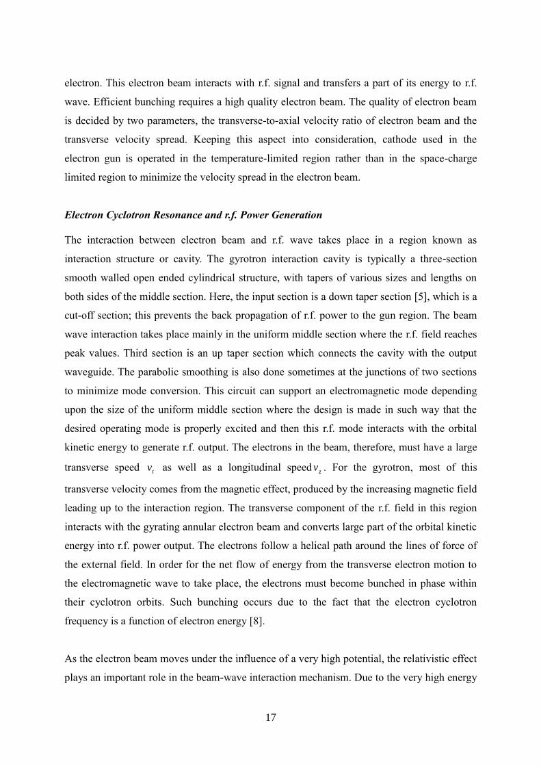
electron. This electron beam interacts with r.f. signal and transfers a part of its energy to r.f.
wave. Efficient bunching requires a high quality electron beam. The quality of electron beam
is decided by two parameters, the transverse-to-axial velocity ratio of electron beam and the
transverse velocity spread. Keeping this aspect into consideration, cathode used in the
electron gun is operated in the temperature-limited region rather than in the space-charge
limited region to minimize the velocity spread in the electron beam.
Electron Cyclotron Resonance and r.f. Power Generation
The interaction between electron beam and r.f. wave takes place in a region known as
interaction structure or cavity. The gyrotron interaction cavity is typically a three-section
smooth walled open ended cylindrical structure, with tapers of various sizes and lengths on
both sides of the middle section. Here, the input section is a down taper section [5], which is a
cut-off section; this prevents the back propagation of r.f. power to the gun region. The beam
wave interaction takes place mainly in the uniform middle section where the r.f. field reaches
peak values. Third section is an up taper section which connects the cavity with the output
waveguide. The parabolic smoothing is also done sometimes at the junctions of two sections
to minimize mode conversion. This circuit can support an electromagnetic mode depending
upon the size of the uniform middle section where the design is made in such way that the
desired operating mode is properly excited and then this r.f. mode interacts with the orbital
kinetic energy to generate r.f. output. The electrons in the beam, therefore, must have a large
transverse speed tv as well as a longitudinal speed zv . For the gyrotron, most of this
transverse velocity comes from the magnetic effect, produced by the increasing magnetic field
leading up to the interaction region. The transverse component of the r.f. field in this region
interacts with the gyrating annular electron beam and converts large part of the orbital kinetic
energy into r.f. power output. The electrons follow a helical path around the lines of force of
the external field. In order for the net flow of energy from the transverse electron motion to
the electromagnetic wave to take place, the electrons must become bunched in phase within
their cyclotron orbits. Such bunching occurs due to the fact that the electron cyclotron
frequency is a function of electron energy [8].
As the electron beam moves under the influence of a very high potential, the relativistic effect
plays an important role in the beam-wave interaction mechanism. Due to the very high energy
18
of electron beams (and thus very high electron speed), a kind of frequency shift occurs in the
r.f. due to the relativistic Doppler Effect.
In an ECRM (Electron Cyclotron Resonance Maser), electromagnetic energy is radiated by
relativistic electrons gyrating in an external longitudinal magnetic field. The cyclotron
frequency is proportional to the magnetic field Bo and thus cyclotron frequency does not
directly depend on size of resonators or r.f. structure. Because of this aspect, r.f. circuit in a
gyro-device is replaced by a simple structure like a smooth waveguide. Their dimensions are
not limited and, thus, the power handling ability increases manifold as compared to the
conventional slow-wave microwave tubes. The size of the r.f. structure depends on the
operating mode. Higher the mode, larger the size of the waveguide and higher is the power
handling capability. The helical beam produced by the MIG interacts with the electromagnetic
field (in TEmn mode) of the same frequency as the cyclotron frequency when the electron
beam passes through the interaction region. This causes bunching of the electron beam.
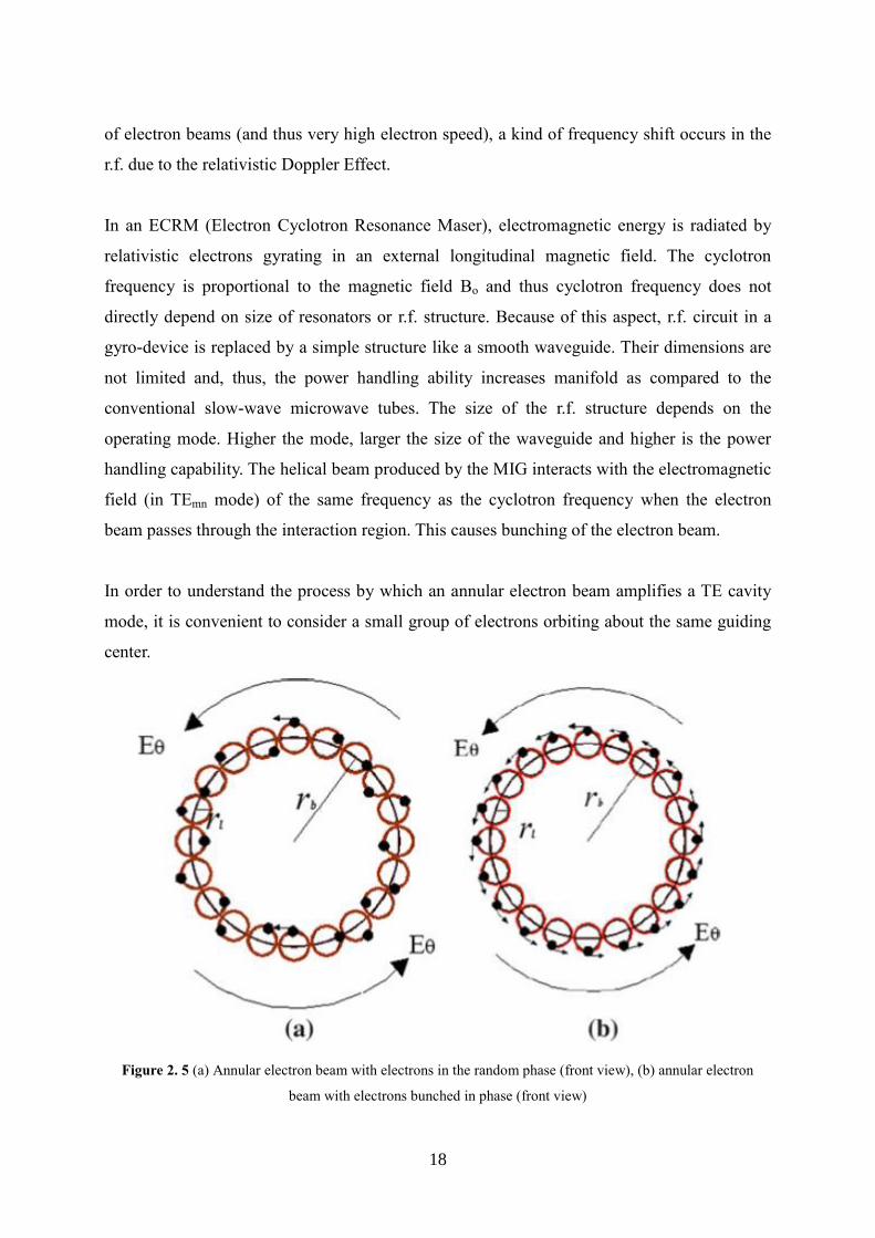
In order to understand the process by which an annular electron beam amplifies a TE cavity
mode, it is convenient to consider a small group of electrons orbiting about the same guiding
center.
Figure 2. 5 (a) Annular electron beam with electrons in the random phase (front view), (b) annular electron
beam with electrons bunched in phase (front view)

19
Figure 2.5 (a) and Figure 2.6 (a) show a cross-section of the electron beam and side view of
the electron beam at the beginning of the interaction region respectively. Here, in Figure. 2.5,
r is the electron beam radius, rl is the larmor radius of electron beam and Eθ is the azimuthal
component of electric field. In the absence of any electric field, the electrons in this beamlet
will orbit around the guiding center with an angular frequency given by Ωe. In the presence of
transverse electric field (E), the electrons experience an additional force eE which cause some
electrons to accelerate and others to decelerate depending on the relative phase of the electric
field.
Figure 2. 6 (a) Annular electron beam with electrons in random phase (side view), (b) Annular electron beam
with electrons bunched in phase (side view)
Due to this mechanism, the electrons ultimately form a bunch as shown in Figure. 2.5(b)
(cross-sectional view) and Figure. 2.6(b) (side view). To understand the phase bunching, it is
convenient to consider a single orbit case.
Figure 2. 7 : Front view of one orbit before electron bunching
20
In Figure. 2.7, electrons 2, 3, and 4 are decelerated, while electrons 6, 7, and 8 are accelerated,
and electrons 1 and 5 are undisturbed. Since the cyclotron frequency is inversely proportional
to relativistic mass factor, the frequency will decrease for accelerated electrons and increase
for decelerated electrons. After few cycles, the electrons that gained energy lag in phase and
the electrons that loose energy advance in phase, resulting in phase bunching. If the electric-
field frequency is exactly equal to the electron cyclotron frequency, this bunching process will
continue until the entire beamlet is bunched at a zero field phase point. In order to extract
power, the bunch must be formed at a field maximum. This is accomplished by a slight
detuning of the axial magnetic field so that the cyclotron frequency is slightly lower than the
r.f. frequency. When this condition is achieved, then the bunches will orbit in phase with the
electric field and give up rotational energy to the TE mode of r.f. field[5,9].
Spent Electron Beam Collection
The collector assembly of gyrotron acts primarily as a dump for the spent electrons. In the
conventional gyrotron, that is, gyrotron with axial r.f. collection (Figure 2.3), the collector
also works as a waveguide for r.f. output. The collector is usually insulated from the gyrotron
main body. This makes it possible to measure the collector current and body current
separately. A reduction in the power density at the collector surface is possible by adding coils
around the collector. This either decreases the derivative of the magnetic induction or makes
the induction along the length of the collector more uniform. Usually, oxygen-free high
conductivity (OFHC) copper is chosen for the gyrotron collector because of its good thermal
conductivity.
Output Power Extraction
The last gyrotron subassembly is r.f. window which acts as an outlet for the r.f. output power
and also functions as a vacuum seal for the tube. It must be fabricated from a low loss
material especially the mode competition problems are dependent on the reflections from the
window. Because of the high power, the thermal management of the output window becomes
an important aspect. The design as well as the choice of the working temperature of the
window has to be carefully done.

21
2.1.2. Gyrotron: State of the art
Today a vast number of research institutes and industries are pursuing activities in the field of
Gyro-devices worldwide and are achieving newer heights in terms of output power and
operating frequency. Some of the state of art development in the field of Gyrotron and Gyro-
TWT are presented below:
Large orbit Gyrotron
For a large orbit Gyrotron, guiding center radius of the electron beam is equal to the Larmor
radius of the gyrating electron. Hence all the electrons have waveguide axis encircling orbits.
Large orbit Gyrotron has got the distinct advantage of the ability to operate at a very high
Cyclotron harmonic number (s>15) reducing the required background magnetic field by many
factors. Large orbit Gyrotron has been reported to deliver peak power of 600 MW at twentieth
Cyclotron harmonic.
Multi Frequency Gyrotron
An oscillator generating r.f. power simultaneously at two frequencies (multimode) is usually
considered as an undesired phenomenon as this makes the oscillator unstable. But in case of
Multi Frequency Gyrotron, this is a desired phenomenon, where the Gyrotron offers stable
oscillation and stable r.f. power simultaneously at a number of frequencies (which are not
harmonically related). This kind of Gyrotron is very useful for controlling the instability of
plasma in thermonuclear reaction. At FZK, Germany, a Gyrotron has been developed which
offered multimegawatt power at 9 different frequencies.
Coaxial Gyrotron
In coaxial Gyrotron, a coaxial cavity is used as the interaction structure. This kind of Gyrotron
has got many advantages over conventional cavity Gyrotron. Central conductor reduces the
voltage depression and corresponding degradation of electronic efficiency. Also, by properly
tapering the outer and/or inner conductor radius, the diffractive quality factor of the desired
mode can be enhanced. And since the start oscillation current is inversely proportional to the
diffractive quality factor, this selective increase in quality factor helps in reducing the chance
of oscillation to be set-in in an undesired mode.

22
2.1.3. Comparison of Gyrotron and Conventional Microwave Tubes
1. In conventional tubes, the r.f. fields with which the electrons must interact are most
intense near the circuit surrounding the beam, so the beam must travel as close to the
circuit as possible. This leads to beam interception and heating of the circuit.
2. In conventional tubes, circuit heating limits power capability.
3. In conventional tubes, circuit dimensions are on the order of the wavelength of the
operating frequency and scale with wavelength so power is severely limited at high
frequencies.
4. In conventional tubes, the r.f. circuit must slow down the phase speed of the signal
approximately to the beam speed. These tubes are referred to as slow wave tubes.
5. In gyrotrons, the field with which the beam must interact is more intense some
distance from the cavity surface. Beam interception problems are far less severe than
in linear-beam tubes.
6. The large dimensions and absence of beam interception in gyrotrons make operation
possible at extremely high powers and frequencies.
2.1.4. Gyro-Amplifiers
These are Gyro-klystrons, gyro-twystron and gyro-TWT. Gyro-Amplifiers are being
developed for applications requiring phase coherence and wide bandwidth. A primary
application is radar where they are of considerable interest for future high –performance
applications. Gyro-amplifiers have large weight and volume than conventional amplifiers but
they can provide significantly higher powers[2].
2.1.5. Gyro-Klystrons
The operation of a Gyro-Klystron, which is again an amplifier, is similar to that of the
conventional Klystron except that electron bunching occurs in the azimuthal direction rather
than in the axial direction. In Gyro-Klystron, input r.f. signal is fed to the first cavity (catcher
cavity) where the cyclotron bunching process is initiated. Then, the beam is permitted to drift.
As the beam passes through a second cavity, the amplified signal may be collected or in case
of multi cavity Gyro-Klystron, the bunching process may be enhanced and the signal is

23
collected in a subsequent cavity. A cross sectional view of a two cavity Gyro-Klystron is
shown in Figure 2.8. The development of Gyro-Klystron has not been pursued vigorously,
apparently, because of the greater promise of Gyro-TWTs [4,10].
Figure 2. 8 : Gyro-klystron Source:[10]
2.1.6. Gyro-Twystrons
The gyro-twystron, like the conventional twystron, is a hybrid device with a modest
bandwidth capability. It is derived from the gyro-klystron by using the gyro –klystron
interaction in the cavities near the r.f. input and by replacing the output cavity with a slightly
tapered waveguide section as in the gyro-TWT to be discussed in the subsequent section. The
output section is excited by the electron beam, which has been bunched by the interaction in
the klystron section.
The configuration of the gyro-twystron can prevent the problem of breakdown at high-power
levels because the r.f. power density in the output waveguide can be much smaller than that in
the gyro-klystron output cavity [2].

24
2.1.7. Gyro–TWT
Gyro-TWT is a high power amplifier. In this device, instead of a cavity, a non-resonant
interaction structure such as waveguide is used. This device has the potential of amplifying r.f.
powers of one order of magnitude larger than what is possible in a conventional TWT and
also provides a high spectral quality. In this device, wideband coalescence is achieved by
adjusting the background magnetic field for grazing point interception i.e. the group speed of
the wave becomes equal to the axial beam speed. Broad-banding of the device is also done by
dispersion shaping of the waveguide by various means such as metallic vane loading, metallic
disc loading, helical corrugation, dielectric loading of the waveguide etc. Multi section Gyro-
TWT is also being developed by incorporating a sever section to suppress backward wave.
Techniques are also being used to increase the bandwidth by tapering the waveguide diameter
and the magnetic field. This technique however reduces the gain of the device as effective
interaction length at a specific frequency becomes smaller [4, 11-16, 56, 66-68, 70, 73-75,
80].
In these devices, a non resonant r.f. structure is used to produce traveling wave interaction. As
in other gyro-devices, a spiralling electron beam immersed in an axial magnetic field is used.
Traveling waves are launched into the interaction space by an input coupler. Axial phase
synchronism is required between the traveling wave and the rotating electrons as indicated in
Figure 2.9.
Figure 2. 9 : Interaction of beamlet with a traveling wave. Source: Advances in Electronics and Electron
Physics, Vol. 55, by R. S. Symons and H. R. Jory, copyright 1981 by Academic Press

25
As the electromagnetic wave and the spiralling electron beam move through the interaction
space, the kinetic energy of the electron beam is transferred into the electromagnetic fields,
creating r.f. amplification. For typical operation near the cutoff frequency of the interaction
waveguide, it is primarily the transverse component of electron motion that interacts with the
electromagnetic wave.
An important problem that must be dealt with in gyro-TWT design is maintaining stability
and preventing backward wave oscillations (BWO) in the interaction space. At the same time,
acceptable performance, including high overall gain, stability to local reflective oscillations,
and high average power capability must also be achieved.
To ensure stability, the majority of this interaction space should exhibit a moderate amount of
electromagnetic loss per unit length. This distributed loading approach has been shown to
have superior stability characteristic compared to the approach using localized lossy severs.
Finally, the downstream part of the interaction space is completed with a short, unloaded
cylindrical tunnel in which the final, highest powered portion of the amplification takes place
[2].