Embed Size (px)
Citation preview
Chapter 2
Input Devices and Mobile Computing
2.1. Introduction 21
2.1 Introduction
For many mobile computers, there is little difference between their text input and the methods for text
input on the typewriters of over a hundred years ago. The keyboards used by many notebook comput-
ers have more keys and functions than the original typewriters, but the layout and interaction methods
are essentially the same, despite a century of progress. On the other hand, many handheld computers,
like the PalmPilot, have forsaken the keyboard in favour of the much more portable stylus input, but this
introduces an entirely new set of limitations.
Unlike text input devices, pointers have varied widely in the past decade alone. In many mobile
systems mice have been replaced by trackballs, trackpads and other novel and more mobile pointers. All
of these new devices are small, but still large enough to impose limits on the size of the device.
New input devices need to be built which are more portable and can free the computer from their
constraints on its size and shape, allowing it to take a more comfortable and efficient form. In order to
design these new devices, we need to review existing and historical input devices focusing on their design
criteria, the extent of their portability, and their performance. By observing the factors which went in to
building these devices we intend to develop an encompassing set of design criteria that we can use to cre-
ate new devices in order to make them as ergonomic and efficient as possible. The portability of existing
devices is examined in order to determine what the limiting factors are. By finding these constraints we
hope to avoid such limitations in the new devices. Examining the performance of existing devices should
provide a basis for comparison by which we can judge the new devices.
2.2 An Overview of Text Input
2.2.1 Conventional and Alternative Keyboards
The keyboard is by far the most common text input for computers. The momentum built up from over
a century of use has guaranteed its dominance despite the problems with both the layout and the basic
keyboard shape. Over the years, several alternatives to the QWERTY keyboard have been developed
which claim to solve some its problems. The first alternative keyboards simply redesigned the key layout
for maximum touch-typing efficiency. More recent ones have reshaped the keyboard in an attempt to
make it more comfortable to use.
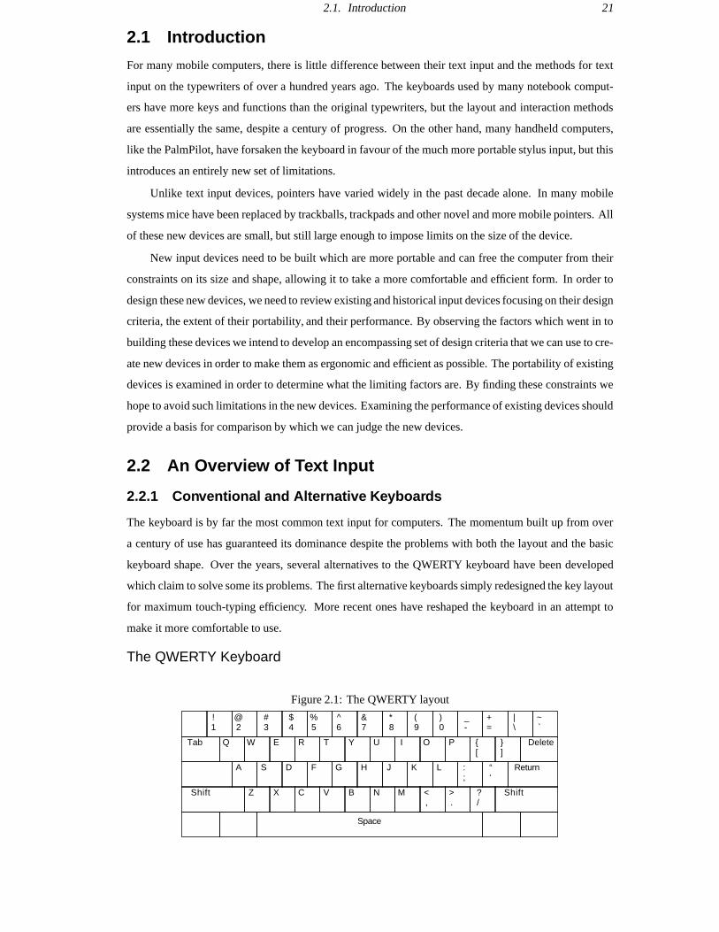
The QWERTY Keyboard
Figure 2.1: The QWERTY layout
!1
@2
#3
$4
%5
^6
&7
*8
(9
)0
_-
+=
Delete Tab Q W E R T Y U I O P {[
~`
|\
}]
A S D F G H J K L :;
“‘
Return
Shift Z X C V B N M <,
>.
?/
Space
Shift

2.2. An Overview of Text Input 22
The first typewriter keyboard was patented in 1868 by Sholes, Glidden, and Soule. Since there were
no data to choose one layout over another, they chose an alphabetic layout. It soon became evident that
because of frequent typebar jams, this layout was impractical. Ten years later Sholes patented the QW-
ERTY layout, which was developed to solve the jamming problem. The QWERTY physically separates
frequent letter pairs, or digrams. Since the keys are further apart, the chance of jamming is reduced, al-
lowing the user to type longer and faster without problems.
The common belief that the QWERTY layout was intended to slow down typists is not true. In fact,
modern studies comparing alphabetic and QWERTY keyboards show that typing on the QWERTY is as
fast or even faster than the alphabetic layout it replaced (Noyes, 1983). However, spacing digrams fur-
ther apart requires the fingers to travel longer distances, and consequently do more work. The seemingly
random placement of the keys on the QWERTY keyboard requires frequent, erratic motions of the fingers
over a small area. These motions are difficult to learn and require a long time for proficiency. Expert-level
typing takes even longer to achieve and quickly decays with disuse (Gopher & Raij, 1988).
The shape of the QWERTY keyboard is ergonomically unsound. The hands are held close together
with the wrists bent outward (ulnar deviation or adduction), and often upwards as well (extension). Ex-
cessive finger use with bent wrists has been linked with Repetitive Strain Injuries (RSI) like tenosynovitis
(Ilg, 1987). Back and shoulder muscle problems can arise from the slouching and hunched shoulders of-
ten caused by poor typing posture.
The Dvorak Simplified Keyboard
Figure 2.2: The Dvorak Simplified Keyboard layout
!1
@2
#3
$4
%5
^6
&7
*8
(9
)0
_-
+=
Delete Tab ?/
<,
>.
P Y F G C R L {[
~`
|\
}]
A O E U I D H T N S “‘
Return
Shift :;
Q J K X B M W V Z
Space
Shift
One of the first alternatives to the QWERTY was the Dvorak Simplified Keyboard. August Dvorak
developed the Simplified Keyboard in 1936 as a solution to the problems of the outdated QWERTY. Sev-
eral design principles were used to solve the problems he saw with the QWERTY keyboard. While these
principles were intended for a keyboard, they can easily be applied to many kinds of input devices.
One design principle was to minimise the distance travelled by the fingers. The QWERTY layout
requires fingers to move large distances because the digrams are placed far apart. The DSK places digrams
close together, reducing the distance fingers travel by as much as 90% (Potosnak, 1988). The QWERTY
was designed for use by two fingers, even though by 1936 touch-typing was standard practice. Dvorak
attacked this problem by distributing the work amongst the fingers, giving the strongest ones the most
work. Also, by noting that simple motions are easier to learn than complex ones, Dvorak was able to

2.2. An Overview of Text Input 23
exploit the frequent use of certain letter sequences, using simple motions to type them. He hoped that
these easier motions would be easier to learn and less tiring than the seemingly random finger motions of
the QWERTY.
There have been several experiments which compare the performances of the DSK and QWERTY.
In general, most of these show that the DSK is on the order of 2%-5% faster than the QWERTY (Potosnak,
1988), which is a minimal improvement. If there is any real advantage it is not that the user types faster,
but that the user does less work. Judging by comments made by users of the DSK, the reduction of finger
work does help reduce typing injuries.
Split Keyboards
Figure 2.3: A generalised split keyboard
Split keyboards are designed to tackle the problem of ulnar deviation when touch typing, in an at-
tempt to reduce typing-related injuries. On a standard keyboard, touch typing is performed by placing the
fingers on the home keys, which are fairly close together. In order to align the fingers on these keys, the
wrists must be bent, with the hands facing outward. A split keyboard straightens the wrists by splitting
the keyboard down the middle (usually along the line between the T-G-B and Y-H-N) and bending the
sides back to make a shape. Some split keyboards are jointed and allow the user to control the angle
between halves. However, most split keyboards have a fixed angle. It has been confirmed experimen-
tally that a split keyboard with a wrist rest can significantly reduce ulnar deviation and wrist extension
(Rempel et al., 1996).
With the rising media interest in RSI, split keyboards have become more common. The Microsoft
Natural Keyboard alone has sold over a million units worldwide (Microsoft Corporation, 1997). Experi-
ments were performed using people with hand and wrist pains on three different kinds of split keyboards
when used over a period of 3 months. The Apple Adjustable and Comfort HealthCare Keyboards showed
a decrease of 18% and 11% in the level of pain, while the Microsoft Natural Keyboard showed a 48% de-
crease in pain levels (Tittiranonda et al., 1996).
While the split keyboard solves some of the ergonomic problems of a standard keyboard, only trained
touch typists benefit from its use. Touch typing assigns each half of the keyboard exclusively to one hand.
A split keyboard physically separates these halves. Touch typists can easily adjust to this because of their

2.2. An Overview of Text Input 24
training. Non-trained typists often will have their own way of typing which does not split the keyboard
in the same manner. These people might find the split keyboard inconvenient to use, thus reducing their
productivity.
Tilt Keyboards
Figure 2.4: Top view of the K-Keyboard, with left and right sections bent downward at 45
Front
Hinges
Down
65
The K-keyboard was developed in 1972 in order to be able to type with the hands in the least stress-
ful position, minimising the strain on the wrists, fingers, and shoulders. In this position, the fingers are
slightly curled, the wrists are straight, and the palms face inward and are tilted at an angle of approxi-
mately to vertical (Kroemer, 1972).
The K-keyboard is split into two boards, one for each hand (Figure 2.4). The boards are tilted down-
ward at an adjustable angle between 0 and 90 , to minimise pronation. Most users preferred an angle
of 45 . Note that at 0 the device effectively becomes a split keyboard. The hinges are tilted forward
at a fixed angle of 25 to minimise wrist extension. Keys are offset to match the length of the fingers.
There is one large curved space bar for the thumb. This arrangement allows the user to hold their hands
in a more comfortable position: with wrists straight and no unnecessary pronation. This is opposed to the
QWERTY keyboard which has the wrists extended, adducted, and fully pronated.
Experiments done on the K-keyboard show some improvement over the QWERTY keyboard. While
there is no significant difference in typing speed, subjects made fewer errors (7.7% vs. 12.7% for QW-
ERTY). In the experiments, subjects were told to type until they were unable to do so. The subjects who
used the QWERTY keyboard tended to stop because of physical pain. Users of the K-keyboard tended
to stop because they could no longer concentrate.
Keyboard Summary
The research carried out on the above keyboards has generated a mass of data on the options for keyboard
design. Many of these have been adopted into national or international standards (International Organiza-
tion for Standardization, 1994). The rest are just good ideas to keep in mind when designing a keyboard.

2.2. An Overview of Text Input 25
In our analysis of keyboards we have uncovered nine important factors for efficient keyboard design.
1. Hand position The least stressful hand position for typing is with the thumbs facing up and inward
at around 45 –60 , palms facing together, and fingers slightly curled (Kroemer, 1972). Reducing
extension and adduction of the wrists has been shown to reduce pain levels up to 48% in people
who suffer from hand or wrist pain (Tittiranonda et al., 1996).
2. Keyboard layout According to ISO9995-3 (International Organization for Standardization, 1994),
the QWERTY is the international standard keyboard with the DSK being the standard alternative
layout. Changes in the layout have little effect on the speed of the device, but minimising finger
travel tends to reduce work and the number of errors (Potosnak, 1988).
3. Keyboard slope (Figure 2.5) Most users prefer a keyboard sloped towards them at an angle of at least
15 (Potosnak, 1988). The preferred slope is related to the user’s hand length and stature. While
the slope of the keyboard affects how much the user likes it, the slope does not affect the users
performance.
Figure 2.5: The preferred slope of a keyboard
15
Figure 2.6: Diagram of a key showing preferredsizes and spacing
19.1mm
12.7mm
Concave top>30mm radius of
curvature
4. Number of keys There is not enough data to know the upper and lower limits for the number of keys
on a keyboard. The only guidelines are the obvious. Too few keys slows typing by requiring mul-
tiple keystrokes to make some characters. Too many keys slows typing by making it harder to find
a specific key (Potosnak, 1988).
5. Key size and shape Keys should be rectangular so they fit well together without large gaps between
them. A square shape is the most preferred design. To guide the finger to the centre of the key, the
tops should be concave, with a radius of at least 30mm (Ilg, 1987). While there is no data for the
upper limit of key size, the lower reasonable limit is 12.7mm square for the key tops, with 19.1mm
between centres (Potosnak, 1988) (Figure 2.6) The typing speed is dependent on the key size. A
square key with a width of 20mm is between 50% and 100% faster than a key width of 5mm (Sears
et al., 1993).
6. Key force and travel Keys should require somewhere between 20cN (0.7oz) and 70cN (2.5oz) of
pressure to activate. The finger should have to travel 4mm to activate the key (Ilg, 1987).
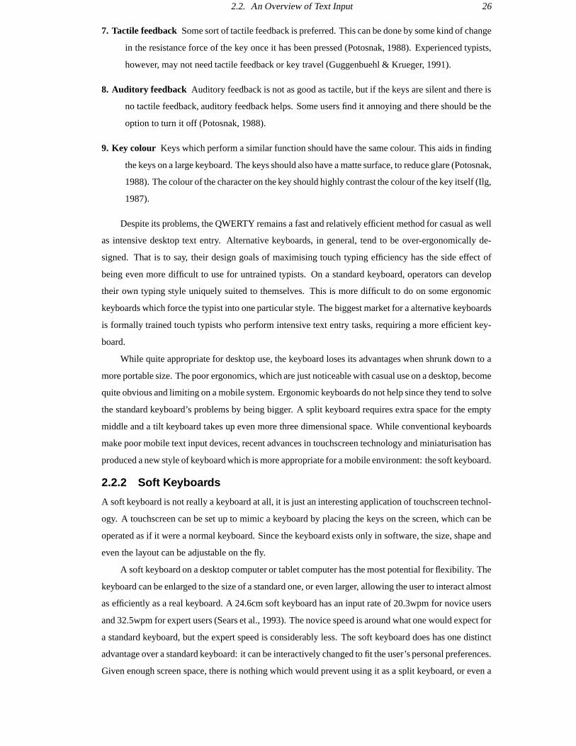
2.2. An Overview of Text Input 26
7. Tactile feedback Some sort of tactile feedback is preferred. This can be done by some kind of change
in the resistance force of the key once it has been pressed (Potosnak, 1988). Experienced typists,
however, may not need tactile feedback or key travel (Guggenbuehl & Krueger, 1991).
8. Auditory feedback Auditory feedback is not as good as tactile, but if the keys are silent and there is
no tactile feedback, auditory feedback helps. Some users find it annoying and there should be the
option to turn it off (Potosnak, 1988).
9. Key colour Keys which perform a similar function should have the same colour. This aids in finding
the keys on a large keyboard. The keys should also have a matte surface, to reduce glare (Potosnak,
1988). The colour of the character on the key should highly contrast the colour of the key itself (Ilg,
1987).
Despite its problems, the QWERTY remains a fast and relatively efficient method for casual as well
as intensive desktop text entry. Alternative keyboards, in general, tend to be over-ergonomically de-
signed. That is to say, their design goals of maximising touch typing efficiency has the side effect of
being even more difficult to use for untrained typists. On a standard keyboard, operators can develop
their own typing style uniquely suited to themselves. This is more difficult to do on some ergonomic
keyboards which force the typist into one particular style. The biggest market for a alternative keyboards
is formally trained touch typists who perform intensive text entry tasks, requiring a more efficient key-
board.
While quite appropriate for desktop use, the keyboard loses its advantages when shrunk down to a
more portable size. The poor ergonomics, which are just noticeable with casual use on a desktop, become
quite obvious and limiting on a mobile system. Ergonomic keyboards do not help since they tend to solve
the standard keyboard’s problems by being bigger. A split keyboard requires extra space for the empty
middle and a tilt keyboard takes up even more three dimensional space. While conventional keyboards
make poor mobile text input devices, recent advances in touchscreen technology and miniaturisation has
produced a new style of keyboard which is more appropriate for a mobile environment: the soft keyboard.
2.2.2 Soft Keyboards
A soft keyboard is not really a keyboard at all, it is just an interesting application of touchscreen technol-
ogy. A touchscreen can be set up to mimic a keyboard by placing the keys on the screen, which can be
operated as if it were a normal keyboard. Since the keyboard exists only in software, the size, shape and
even the layout can be adjustable on the fly.
A soft keyboard on a desktop computer or tablet computer has the most potential for flexibility. The
keyboard can be enlarged to the size of a standard one, or even larger, allowing the user to interact almost
as efficiently as a real keyboard. A 24.6cm soft keyboard has an input rate of 20.3wpm for novice users
and 32.5wpm for expert users (Sears et al., 1993). The novice speed is around what one would expect for
a standard keyboard, but the expert speed is considerably less. The soft keyboard does has one distinct
advantage over a standard keyboard: it can be interactively changed to fit the user’s personal preferences.
Given enough screen space, there is nothing which would prevent using it as a split keyboard, or even a
2.2. An Overview of Text Input 27
chord keyboard (see Section 2.2.3). This is a flexibility impossible on any “hard” keyboard.
The smaller displays of notepad-size computers prove to be quite limiting to the flexibility of the
soft keyboard. There is not enough space to resize it to a convenient size or shape. The best one could
hope for is to be able to get rid of the keyboard when not using it. Input speeds for a 6.8cm soft keyboard
are 9.9wpm for a novice and 21.1 for an expert (Sears et al., 1993), significantly less than the speed on
the large keyboard, but the room for improvement is much larger. On the smaller keyboard an expert will
type 113% faster, as compared to the large keyboard where the expert only types 60% faster. The wide
proliferation of mobile computers begs the question of what percentage of users can possibly be experts.
The benefits of expert use may not be applicable to the majority of users.
The limitations in typing speed due to the cramped space of a smaller keyboard can be offset by us-
ing a stylus to tap on the keys instead of typing with the fingers. A theoretical analysis of upper and lower
bounds to the input speed yields a range of 8.9wpm to 30.1wpm for any reasonably sized soft keyboard
(Soukoreff & MacKenzie, 1995). Experimental results show that a novice user should expect around
21.1wpm (MacKenzie et al., 1997). This means that, as a keyboard size decreases, typing becomes more
difficult, but tapping with a stylus remains just as effective. While this has no benefits for a desktop com-
puter, a small handheld computer would benefit greatly.
There are two major problems of a soft keyboard which have not been addressed so far. The first is
the lack of tactile feedback. The lack of feedback requires the user be constantly looking at the screen
to know if they hit the correct key. This can be compensated somewhat by audible feedback, which can
be performed by a beep from the computer whenever a key is hit. However some users find this rather
annoying and it should not be depended upon (Potosnak, 1988).
The other major problem is that a soft keyboard takes up valuable screen real-estate. This is espe-
cially a problem for miniaturised computers where the keyboard must take up most of the screen to be
usable, even with a stylus. As a result, the soft keyboard really cannot be used as a primary text input
device for a mobile computer. However, it can make a useful secondary, backup text input for when the
primary input (e.g. handwriting recognition) fails.
The soft keyboard solves the size problem by squeezing the keys into as small a space as possible.
This exacerbates the problems of the poor ergonomics of the standard keyboard to the point where normal
typing is impossible. Typing with a stylus does improve the interaction, but there is still the problem of the
keyboard taking up much of the screen space. This leaves us with a text input device which can be used
efficiently with a mobile computer, but may not be appropriate for significant amounts of text input. We
still need a primary text input device which is designed to be small, not shrunk down as an afterthought.
In the following sections we will discuss input devices which do not suffer the same size limitations of
keyboards.
2.2.3 Chord Keyboards
All the keyboard alternatives discussed above are just modified versions of the standard keyboard. A
character is made by pressing one key, or one key in combination with one (or more) shift keys. This
allows any number of characters, as long as there is room on the keyboard. A chord keyboard takes a

2.2. An Overview of Text Input 28
different approach. There is one key for each finger. Multiple keys are pressed simultaneously to create
characters, in the same way that a chord is made on a piano. Pressing combinations of keys in this way
is called chording.
Chord keyboards were first used by the US Post Office in the 1960’s for entering numbers for mail
sorting (Potosnak, 1988). Most early research on chord keyboards concentrated on limited applications,
such as entering numeric data. In the 1980’s chord keyboards were reevaluated and applied towards a
general text keyboard. The first thing which needed to be solved before this could happen was the limited
number of characters. A one handed chord keyboard has only five keys. This translates to 31 possible
combinations. This is enough for all the letters, with room for a few more characters, like Space
and Return . There are numerous ways to increase the number of characters beyond just 31. The
following are just some of them:
Two handed chording A ten key chord keyboard has 1023 possible characters. This more than enough
for general text input.
Thumb keys One or more extra keys can be added in reach of the thumb. Sixteen more characters are
added per thumb key. More combinations are possible if the thumb keys can be pressed simulta-
neously. This is the most common solution.
Sticky shift keys A sticky shift, when pressed once, acts on the next one chord. When double-pressed
(like double-clicking a mouse) it acts on all chords until the shift is hit again. For each shift, the
number of possible characters doubles.
Multiple state keys Instead of an on/off key like most keyboards, it is possible to have a three or more
state key. A three state keyboard uses keys which can be pushed up, down, or not at all. This gives
243 combinations for one hand.
Additional finger keys It is possible to have more than one key per finger, such as an extra row, above
or below the base row. This is effectively the same as using multiple state keys.
By using one or more of these combinations it is possible to create all the same characters that can
be made on a standard keyboard. With this problem removed, it is possible to use a chord keyboard as a
general text input device.
The biggest advantage of chord keyboards is that they can be made significantly smaller than a stan-
dard keyboard. Each finger presses only one key, so that key can be placed in the keyboard in the most
efficient position. In practice, most chord keyboards are around the size of the hand. The palm rests on
an empty base, while the fingers press keys located radially around it (Figure 2.7). This setup permits a
full range of text input, but at a fraction of the size, with no real loss of comfort.
The chord keyboard suffers from a similar problem to the split keyboard. Arranging each half of a
split keyboard for each hand leaves an empty gap in the middle (Figure 2.3). The size of a chord keyboard
is not limited by the size of the keys, since half a dozen or so small keys cannot take up much space. The
problem is space between the keys. In the chord keyboard shown in Figure 2.7, most of the device is

2.2. An Overview of Text Input 29
index
middle
ring
little
wrist rest
thumb
shift
Figure 2.7: A generalised chord keyboard
covered by the hand or the fingers, making the device unnecessarily big. One solution to this problem
is to put the keys on a small box which is held or strapped to the palm of the hand. This style of chord
keyboard takes up much less space, but it can also hinder the user’s interactions when performing real-
world tasks. Extra time must be spent putting the device down, or, if strapped in, it might get in the way
of the user’s actions.
Another disadvantage of chord keyboards is that the fastest typists will always type faster on a stan-
dard keyboard. The reason for this is key overlap. On a standard keyboard, one often presses more than
one key at a time. The key which is pressed first is entered first, but another key is in the process of be-
ing pressed. That means up to ten characters can simultaneously be in the process of being made. A one
handed chord keyboard can make only one character at a time. There is no overlap. For the novice typist,
this is not a problem. Novices can chord faster on a chord keyboard with less training. After twenty hours
of training a one-handed chord keyboard user averages around 29wpm, while a QWERTY user averages
around 20wpm. After 35 hours of use a chord keyboard levels off around 36wpm (Gopher & Raij, 1988).
A further disadvantage is that it is not possible to type without training on a chord keyboard, although
it is possible is on a standard one. On the other hand, learning to type on a chord keyboard is easier because
the chord shapes can have some physical correspondence to the letter being created. For example, holding
out only the thumb and little finger makes a Y shape. If the chord for Y is made with the thumb and little
finger, it becomes much easier to remember. The chords for an entire character set can usually be learned
within an hour (Gopher & Raij, 1988).
One advantage chord keyboards have over alternative layouts, like the DSK, is that learning to type

2.2. An Overview of Text Input 30
on a chord keyboard does not have any effect on the ability to type on a standard one. A person can switch
back and forth without any problem. Touch-typing on a standard keyboard is difficult because the large
number of keys and movements make it easy to miss a key. This problem is partly alleviated by most
alternative keyboards. With a chord keyboard each finger uses only one key, since almost no movement
is involved, it is impossible to miss a key. This is especially useful for blind, or otherwise disabled users.
The benefits of reduced motion are reflected in the smaller error rates for chord keyboards.
2.2.4 Handwriting Recognition
Handwriting recognition is a particularly attractive method for text input, given the extremely wide pro-
ficiency of writing in the population. In the ideal case a handwriting recognition system would be as easy
to use as writing on paper. Anyone who can write could pick up the device for the first time and bypass all
the time normally spent learning to use the interface. Input speeds are comparable to novice QWERTY
speeds, with printing speeds ranging from 12wpm to 23wpm. Speeds for cursive writing are higher rang-
ing from 16wpm to over 30wpm (Soukoreff & MacKenzie, 1995), but character recognition, even by a
human, is much more difficult.
C u r i o u s e r a n d
(a) Text input by writing sequentially on the screen
Curiouser and curiouser! cried Alice (she wa
(b) Text input by writing each character in a special block
Figure 2.8: Two methods for handwriting recognition
Most handwriting recognition systems use one of two methods for input. The first is writing on the
screen itself. In this method, input area is set up as a series of blanks, which are filled in sequentially, one
character per blank (Figure 2.8(a)), much like filling out a form on paper. This method requires the stylus
to be positioned over each character. While this may not take up much space, it may cause problems
since the hand might cover up parts of the screen. It also has the disadvantages of requiring constant
visual supervision. If the stylus is slightly offset from where the user thinks it is, a character could be
incorrectly recognised or printed in the wrong place. Finally, the sequential method of writing translates
poorly to a heads-up display, since it would require a full sized pad to write on, in addition to the display.
The second method for handwriting recognition is writing in place. This consists of writing on a
special block outside the main part of the screen (Figure 2.8(b)). Each character is written in the block,
one on top of the next. The character is inserted on the screen at the location of the cursor, just as it is
done with a keyboard. The cursor can be positioned by using the stylus as the graphic input device as well.
This simplifies the recognition by adding a constraint on the position . It also avoids the problem of hand
occluding the display while writing. There is the added benefit of causing less fatigue by minimising hand
motions (Goldberg & Richardson, 1993). As long as the stylus starts out in the correct position, visual

2.2. An Overview of Text Input 31
supervision is unnecessary. In fact, the handwriting recognition block need not even be on the screen at
all. Writing in place would translate well to a heads-up display, where characters could be written on very
small pad outside of the field of vision and displayed on a monitor in front of an eye.
In addition to the two methods for handwriting recognition, many systems also include a soft key-
board which can be displayed to allow an alternative to writing. This is especially useful when enter-
ing less frequently used punctuation or other hard-to-recognise characters. While a soft keyboard allows
faster text entry than handwriting, it is not sufficient for primary use because of the possibility of fatigue
with long-term use (MacKenzie et al., 1997).
At the time of writing, handwriting recognition is far from perfect. The general agreement is that
to be widely accepted, a handwriting recognition system would have to have 97% or higher accuracy
(MacKenzie & Zhang, 1997). For isolated printed characters, human recognition is 96.8%, just short of
what we would require from a computer. One advantage a handwriting recognition system has over a
human reader in that it has temporal information as well. For example, the computer would know the
difference between two very closely spaced v’s and a w because it would have seen the stylus lift from
the tablet in between characters. This could help a handwriting recognition system achieve the desired
levels of accuracy.
The current state of the art for handwriting recognition yields an accuracy between 87% and 93%
(MacKenzie & Chang, 1997). This falls short of the 97% needed to be widely accepted. In addition,
these figures were more effected by the user’s adaptations to the quirks of device, rather than the device’s
recognition techniques.
The underlying problem with handwriting recognition is that Roman characters are not well suited
for computer recognition. Next two sections will discuss two handwriting recognition systems which
bypass this problem by reshaping the alphabet to a much simpler form.
Unistrokes
Figure 2.9: The five basic strokes in the unistroke alphabet
Unistrokes were designed to provide a fast, easy to recognise alternative to the standard Roman char-
acter set (Goldberg & Richardson, 1993). The characters are generated from a basic set of 5 different
strokes, each one made by up to 3 simple motions (Figure 2.9). Each of the 5 strokes has 4 possible ori-
entations and can be drawn from 2 different directions. This yields 40 possible characters that are different
enough to be easily differentiated by a computer. The entire printable ASCII character set can be covered
by using shift keys, or some of the other methods mentioned in Section 2.2.3 for increasing the character
range for chord keyboards. Another key design factor is that unistrokes are designed specifically to use
the writing in place method for character entry. This further facilitates writing for the user and character

2.2. An Overview of Text Input 32
differentiation for the device.
Unistrokes can be entered quite quickly, with a novice input speed of 34wpm. It is expected that
entry rates can go as high as 41wpm for expert users. The novice rate is faster than normal printed text
(12–23wpm) and is around the same speed as the upper end of the cursive entry rate (30+wpm). The
unistroke character set can be learned within 10 minutes of use, but it takes a week of practice to achieve
the novice input rate of 34wpm. No error rates were mentioned in the literature.
Unistrokes were intended for “power” users who would use a stylus input enough to benefit from
the extra time spent learning the system. Since the handheld market was risky enough to begin with, the
manufacturers of these systems had little inclination to cater to a small section of an already specialised
market. While it was acknowledged that unistrokes were a good idea, there was little desire to try it.
Graffiti
Graffiti was introduced as an attempt to bring the unistroke idea of a simplified alphabet to a mass market.
Instead of simplifying all the letters to the extent where text more resembles Cuniform than English, the
letters of the alphabet are simplified just far enough to make them easily differentiated by a computer, but
remain recognisable to a human. All but five of Graffiti’s letters have a strong resemblance to the Roman
Character, and even the remaining five still retain an obvious relationship.
The benefit of Graffiti’s approach is that it is very easy to learn. The initial accuracy for the system
is 86%. After five minutes of practice the accuracy goes up to 97%, which meets the above-mentioned
requirements for an acceptable handwriting recognition system. With continued use recognition levels
may reach up to 99%. The accuracy after one week without using the system at all is 97%, implying that
the Graffiti alphabet is retained in long-term memory (MacKenzie & Zhang, 1997). Text entry rates are
claimed by the manufacturer to be around 30wpm (US Robotics, 1996).
Graffiti was developed by Palm Computing as a commercial text entry system for handheld com-
puters. While the Graffiti software is available for several different systems, it comes standard with Palm
Computing’s PalmPilot personal organiser. The PalmPilot currently enjoys 66% of the handheld market
(McCall, 1997) which shows that Graffiti has been rather successful at its intended job. However it is
generally thought that Graffiti must be a short term solution to allow handheld computers to get off the
ground while effective general handwriting recognition systems can be developed.
2.2.5 Glove-Based Text Entry
One of the more novel text input methods is text input via a glove-based device. These devices use one
or both hands to input text by either sensing the motion involved with gestures or by detecting contact
between the fingers and other fingers or a special pad. These devices tend to be quite portable because
the glove is worn instead of held and consequently is lightweight and takes up very little space.
Hand Gestures
Several systems have been developed to recognise sign language. The first such device was the Digi-
tal Data Entry Glove (Grimes, 1983), which was developed to recognise the letters in American Sign
Language to provide a more portable and comfortable text input device. This glove used three kinds of

2.2. An Overview of Text Input 33
sensors: flex sensors on the joints to measure finger flexion, inertial sensors to detect orientation, and
contact sensors to detect finger adduction and contact between parts of the hand. The basic theory was
sound, but it turned out to be impractical since the contact sensors required excessively precise finger po-
sitions in order to be recognised. In addition, the recognition was hard-coded into the device, preventing
any adaptation to the user. While a commercial device was never built, this glove did pave the way for
the DataGlove (Zimmerman & Lanier, 1987) which was partly influenced by this design.
A second system based on both Grimes (1983) and the DataGlove used sign language recognition
for computer mediated communication (Kramer et al., 1991). The primary intention was to use the com-
puter to help facilitate communication by deaf people by translating the hand motions of sign language
into characters, which could then be spoken by a synthesised voice. However, there is nothing to prevent
this system from being used purely for text input. The glove in this system, the CyberGlove, improved
upon the DataGlove’s optical fibre joint sensors by using strain gauges which give more accurate joint
angles over a wider range. Strain gauges on the joints of each finger and the wrist measure the flexion
angles. Additional strain gauges are positioned between the fingers, and on the thumb and wrist to mea-
sure adduction, abduction and opposition. This system uses an adaptive pattern recognition system to
recognise the sign language characters and has been released commercially as the GesturePlusTM. An
experienced user can reach input speeds of over 40wpm (Virtual Technologies Inc, 1997). Unfortunately,
this requires top-of-the-line equipment at a cost of over US$10,000 (Burdea & Coiffet, 1994). Despite
its high portability, the high cost of this system prevents its use as an everyday text input system.
The GloveTalk uses a DataGlove to convert the gestures of a specialised sign language into speech
(Fels & Hinton, 1993). The number of words is limited, with 66 root words and 5 possible suffixes (‘-s’,
‘-ly’, etc.), but these can be created in near-real time by one hand. Since each motion is a word which
must be recognised by the computer before it can be spoken, it is possible to do away with the vocal aspect
of the system and use it for text input only. The major problems with such a system is low vocabulary and
high cost, which limit its usability as a text input device. A later version of this device, the GloveTalkII,
uses two gloves and a foot-peddle to create individual formants which can be combined to speak at a third
to nearly half of the normal rate. While the speed is fast for text input, the learning time is over 100 hours,
which makes it unlikely to be a widely usable text input device (Fels & Hinton, 1995).
Contact Gestures
Contact gloves are a somewhat cheaper and computationally simpler alternative to gesture recognition.
These devices sense contact between fingers and either the hand, other fingers, or a special tablet. Touch-
ing contacts completes a circuit between the two sensors, which is detected by the computer. The gestures
which make these contacts can be converted into characters or act as function keys.
Hartwig (1978) describes a contact glove used to enter numbers. The glove has contacts on each fin-
ger. These are touched against a special tablet, which is divided into 3 sections. Each section can produce
one of five characters, depending on the finger which touches it. The first section contains the numbers
1–5, the second section contains the numbers 6–9 and 0, and the third section contains the symbols +
- and =. This style of contact glove is equivalent to a keyboard which produces a different charac-
2.2. An Overview of Text Input 34
ter depending on which finger is used to press the key. There is no research indicating the performance
of such devices. However, it is clear that hitting the tablet in the correct place requires visual supervi-
sion. This limits the position of the tablet to where it can be easily viewed and also prevents the use of a
heads-up display. As a consequence this system would be less mobile than a glove-only system.
Another contact glove, the Pinch glove makes gestures by touching fingers against each other
(Holands, 1996). This is more mobile than Hartwig’s glove, since it does not require a tablet. Unfor-
tunately, it can only be used for function input, since there are too few combinations to enter a decent
fraction of the 100 printable ASCII characters. Using two gloves, or increasing the number of contacts
on one might allow enough gestures to enter the alphabet, but it could suffer similar problems to the Dig-
ital Data Entry Glove, where the finger combinations were too complex to be easily made.
In summary, glove-based text entry is extremely well suited for use in a mobile environment. The
biggest drawback is the difficulty is recognising enough separate gestures to allow useful text input. Dif-
ferentiation between the large number of gestures necessary for text input on a contact glove requires
excessive precision, limiting their usefulness. Contact with a separate tablet allows easier gestures, but
at a loss of mobility. Gloves like the CyberGlove, which sense the full orientation of the hand, can be
used to recognise existing sign language for text input, but the prohibitive cost of these devices precludes
their everyday use.
2.2.6 Voice
In some ways voice is the ideal text input device. A microphone takes up practically no space, has neg-
ligible weight, and is completely hands-free. It can be used just as easily in almost any environment and
conditions. It is also much faster than most other text input devices, with an input speed on the order of
150wpm (Dragon Systems, 1998). However, the technology is based on pattern recognition, which limits
its usefulness.
Speech recognition systems perform a number of steps in converting an individual utterance into a
word (Scahill et al., 1996). First, the utterance is divided into individual sound units called phonemes.
The phonemes are then decorrelated to extract certain features. This simplified model of the utterance is
compared to a known vocabulary, from which the most appropriate match is selected.
The last step of this process shows the two main sources of trouble for speech recognition systems:
vocabulary and accuracy (Hunt, 1997). The vocabulary size needed to use a speech recognition system
as a general text input is between 5000 and 60,000 words. One existing commercial system, the Dragon
NaturallySpeakingTM Deluxe, can maintain a 30,000–50,000 word active vocabulary, and a total vocab-
ulary of 230,000 words (Dragon Systems, 1998). The need to change vocabularies and the potentially
high memory use are relatively minor problems brought about by the size of the active vocabulary. The
main problem is the difficulty of recognition: the more words there are to choose from, the more difficult
it is to differentiate between them.
A high accuracy is essential for a speech recognition system. Not only does the system need to cor-
rectly recognise the words, but it also needs to reject invalid input (coughs, “um”s, etc.). Consequently,
a system must have a rejection threshold. This is the point at which, if the match is not good enough, the

2.2. An Overview of Text Input 35
utterance is ignored. This leads to three different kinds of recognition errors. The first is a substitution
error, which is made when a valid utterance is incorrectly interpreted as a different word. A second error
is an insertion error, which is made when an invalid utterance is mistakenly identified as valid input. The
last error is a deletion error, which is made when the quality of a valid utterance is below the threshold,
and it is considered invalid (Johnston, 1996).
Setting the rejection threshold too low will cause more false acceptances (substitution and rejection
errors), allowing potentially harmful events to occur, e.g. confusing “(cough) read file” for “delete file”.
Alternatively, setting the threshold too high will cause more false rejections (deletion errors), annoying
the user either by ignoring their input or by constantly asking them to repeat themselves. Consequently,
for speech recognition systems, high accuracy is not enough. The systems must also have a good method
for safely handling errors.
Another problem with speech recognition system is the issue of privacy. Privacy is not much of an
issue in a working environment. In a work environment, a mobile computer would be mostly used for in-
put tasks such as inventory or damage control, or communication tasks, such as accessing an information
database to assist in performing some work. In either case, voice control is useful, and allows the user to
work hands free. Vocal text input is ideal for these situations.
The problem arises in personal computing. The nature of mobile computing means the computers
are just as likely to be used in a public environment as not. In general, one is unlikely to want to write
sensitive work-related or personal documents in public. Even if the speech recognition was performed
flawlessly, people would still want some private way of interacting with the computer. For a computer
which is likely to be used in public, the option of non-vocal input is necessary, even if it is only used as
a backup.
2.2.7 Summary of Text Input Devices
The QWERTY keyboard is extremely popular as a text input device due to the momentum built up from
over a hundred years of use. However, the QWERTY’s design is not ergonomically sound. The hands are
held close together with the wrists extended and bent outward. This has been linked to cases of RSI in full
sized keyboards. If the QWERTY is shrunk, the strained conditions are made even worse, giving more
potential for injury. The poor ergonomics of the QWERTY and the rising popularity of mobile computers
has caused a surge of alternative methods for text entry.
Ergonomically designed keyboards tend to solve the QWERTY’s problems by repositioning the keys
for maximum efficiency when touch typing. This is usually done by separating the keys in some manner,
which has the side effect of making the keyboard bigger. While this might be a great benefit for people
working in office conditions, it makes the problem of mobile computing even worse.
Part of the problem of the poor ergonomics of a shrunken QWERTY can be solved by using a soft
keyboard. These devices can be adjusted on the fly to fit the ergonomic needs of the user. However, this
is rarely done in practice, and instead the more popular solution is to use a stylus to tap the keys, one at a
time. This reduces the strain of touch typing in such a small area, but text entry speeds are significantly
reduced. These facts lead to the conclusion that conventional keyboards are undesirable for mobile com-
2.3. An Overview of Pointer Input 36
puter inputs. Soft keyboards, on the other hand, are adaptable enough to make them a useful backup text
input.
Chord keyboards have a comparatively small number of keys, allowing touch-typing in confined
areas without reduced comfort. A chord keyboard is not as fast as a desktop keyboard for an expert,
but it can achieve quite reasonable speeds for novice users, and with less training than a keyboard. The
36wpm expert speed on a chord keyboard is roughly the same as the higher end of expected speeds on
most handwriting systems. Chording does have the advantage of being potentially less fatiguing than
handwriting systems since there is minimal movement and no stylus needs to be held. The biggest hurdle
to overcome with chord keyboards is that the keymap must be learned before it can be used, even though
the alphabet can usually be learned within an hour. But, if we can learn anything from unistrokes it is that
the market is very hesitant to embrace such a technology.
Modern handwriting recognition systems are not flexible enough to analyse general handwriting.
Instead the most effective systems require the user to learn a simplified alphabet, like Graffiti. Writing in
place at the end of the workspace removes the need for moving the wrist and minimises the finger work.
While this is slower than a desktop keyboard, it is less fatiguing, and remains one of the best options for
a mobile interface.
Glove-based gesture systems are also highly portable, but they suffer from excessive cost or poor
accuracy. Contact gloves are affordable enough for everyday use, but they are might not be accurate
enough to recognise the large number of gestures needed for text entry. Gloves which can sense the full
orientation of the hand can learn to recognise enough gestures for text entry, but these are too expensive
for casual use.
Speech recognition systems provide an extremely portable, hands-free text input method. As of this
writing the widespread use is limited primarily by the vocabulary size and accuracy of these systems.
These are purely technological constraints which may be solved in the near future. However, even with
near-perfect accuracy, recognition errors are inevitable, thus necessitating a safe method for avoiding po-
tentially damaging misinterpretations. While speech recognition is a useful text input method, there are
situations in which vocal input is inconvenient or undesirable. Consequently, it is a good idea to back up
voice input with a silent text input alternative.
As it stands, a handwriting system using a simplified alphabet, speech recognition, a contact glove
with a tablet, or a chord keyboard, are the text inputs most suited for use with a mobile computer. The
handwriting system, speech interface, and chord keyboard are effective on a heads-up style system while
conventional handwriting and the contact glove are more effective on a notepad-style system. The next
step in designing a mobile input is to look at the options for graphic input devices and determine which
of them can work effectively in a mobile environment.
2.3 An Overview of Pointer InputNumerous pointer input devices have been developed over the last few decades as a result of the trend in
computers to a more graphically oriented interface. Most of the more recent developments with pointers
take advantage of the advancements in computing power and miniaturisation. But the most recent spurt

2.3. An Overview of Pointer Input 37
in novel pointers has grown from the need for a device which works effectively in a mobile environment.
Many of the design criteria for text input devices also apply to graphic input devices. For example,
the ideas of minimising work and using tactile or auditory feedback make as much sense for pointing as
the do for typing. Consequently, in this section, we will be concentrating more on the factors which limit
portability, and the performances of the devices.
With text input devices, performance was judged quantitatively, primarily by a device’s input speed.
It is necessary to use a similar quantitative method for comparing the performance of graphic input de-
vices. In the early 1950’s Fitts developed a method for measuring the performance of human motion.
While this was originally applied to ergonomics and kinematics, Fitts’ law has been adopted into the field
of Human Computer Interaction as a tool for comparing graphic input devices.
2.3.1 Fitts’ Law
Fitts’ law is an application of information theory to motor coordination which provides a metric for com-
paring various graphic input devices in simple pointing tasks (MacKenzie, 1992). The model is based on
Shannon’s Theorem 17, which describes the information capacity of a channel with a finite bandwidth
in terms of signal power and noise power :
(2.1)
The bandwidth is measured in Hz and the capacity is measured in bits per second.
Fitts applied this law to human motor coordination by finding the appropriate analogues for the
terms. Channel capacity becomes the index of performance, IP. The inverse of the bandwidth ( )
becomes the movement time, MT, which is the time it takes to perform a specific motion. The strength of
the signal becomes the amplitude of the motion . The noise in the signal becomes the width of the
destination of the motion. The yields the modified equation:
(2.2)
where Fitts’ logarithmic term of replaces Shannon’s logarithmic term. The 2 is an arbitrary constant
to ensure that IP is positive when the motion starts outside the destination region.
The term in the numerator is the log of the ratio of the size of the motion to the size of region in
which it ends. This is called the index of difficulty (ID):
(2.3)
Using this term, Fitts’ law can be rewritten as:
(2.4)
Since ID and MT are known terms, this equation can be solved directly. However the results are somewhat
lacking as it does not provide a term for reaction time, which turns out to be necessary.
Equation 2.4 can be rewritten, solving for MT, as:
(2.5)

2.3. An Overview of Pointer Input 38
which can, in turn, be solved by performing a linear least squares fit on the known variables, ID and MT:
(2.6)
where is the reaction time and IP = .
By using Equation 2.6, the index of performance of a graphic input device can be found. IP, as we
recall, is measured in bits/s. Applying this to an input device tells us how fast information can be sent
from user to computer. This yields a useful method for comparing effectiveness of various graphic input
devices.
Note that the term in ID is unitless, and is unchanged under any scaling. This means that the time
it takes to perform a motion (MT) is independent of the scale of the device. This is limited to situations
involving the same Index of Performance. If the system is scaled up to the point where new muscles
are involved in the action, a new IP is involved. This is why tapping on a soft keyboard with a stylus is
equally fast, regardless of the size of the keyboard. A small soft keyboard would require motions from
only the wrist, while a large one would require motion mostly at the elbow. These actions have differing
IPs (Balakrishnan & MacKenzie, 1997) and thus would take different amounts of time to perform.
Unfortunately there are some problems of consistency from experiment to experiment when using
Fitts’ Law. Different experimental setups can give widely ranging values for the same device. For exam-
ple, in different experiments, the mouse has been found to have an IP as low as 2.6 and as high as 10.4
(MacKenzie, 1992). Fortunately, the ratio of IPs is more or less constant from experiment to experiment.
For example, in the experiments above the joystick was found to have IPs of 1.2 and 4.5 respectively.
This gives joystick to mouse IP ratios of 0.46 and 0.43, which are very close. As a consequence of this,
ratios of IPs should be used to compare the performances of devices checked in different experimental
setups. In this thesis we will be using a “normalised” version of Fitts’ law in which the performance is
calculated by the IP of the device divided by the median value of the IP for the mouse, as calculated in
the same experimental setup. In other words:
mouse(2.7)
The mouse was chosen because of its widespread use and relatively high performance. This method is
used in Table 2.1 to rate the performances of various common graphic input devices.
It is obvious that a consistent standard for rating graphic input devices is necessary. At the time of
this writing, the International Organisation of Standardization is working on ISO 9241-9: “Requirements
for non-keyboard input devices”. This is still in the committee draft stage, but it is expected to propose
a method based on Fitts’ Law for comparing graphic input devices (MacKenzie & Oniszczak, 1998). In
this proposal, the Index of Performance (IP) is renamed Throughput (TP), and a set of consistent rules for
measuring it are laid out. Unfortunately, nothing official has been published. As a consequence it is only
included here as a reference for future research. All comparisons of graphic input devices in this thesis
will be based solely on Fitts’ law as described above.

2.3. An Overview of Pointer Input 39
ExperimentMacKenzie &
Oniszczak(1998)
I. Scott MacKen-zie & Buxton
(1991)
Epps (1986) Card et al.(1978)
Mithal &Douglas(1996)
stylus 1.09
mouse 0.80–1.20 1.00 1.00 1.00 1.00
trackball 0.53–0.93 0.73 1.15
trackpoint 0.71
touchpad 0.62–0.88
joystick 0.42–0.46 0.43
Dev
ice
trackpad 0.26–0.29
Table 2.1: A comparison of the normalised performance of six graphic input devices. The performancevalue is the ratio of the device’s IP to the median IP calculated for the mouse in the same experiment.
2.3.2 Arrow Keys
The earliest personal computers were almost entirely text-based and had little graphic capability. Arrow
keys located on the keyboard were used for pointer control. There are various methods for interaction
with arrow keys, the most common of which is step keys. These move the cursor up or down one line and
back or forward one character. In a graphic environment step keys move the pointer one or more pixels,
the size of the step often changeable by either another set of keys, or as a function of the duration of the
key press. Jump keys are designed for a more specific type of environment. Jump keys move the cursor
to one of a series of predefined areas on the screen. This is often used in hypertext applications to jump
between links. It has been shown that jump keys are faster and more preferable than using a mouse in a
text-only hypertext system (Greenstein & Arnaut, 1988). This has not been proven for complicated text
and graphic windows-based environments.
The simplicity of arrow keys makes them a very versatile graphic input method. Arrow keys can be
made very small to fit various sized devices, while still retaining the same level of usability. While arrow
keys are not terribly fast nor efficient for general graphic interaction, they do make a decent backup pointer
control. There is no Fitts Law data for the performance of arrow keys.
2.3.3 Joystick
A joystick is a vertical handle mounted on a base, usually with one or more buttons used for selection.
A displacement joystick uses potentiometers or similar technology to measure the displacement of the
handle from the normal position. This is translated to a magnitude and direction. Springs are often used
to move the handle back into its normal position. An isometric joystick uses strain gauges to measure the
force on the handle. The handle itself does not move. A switch activated joystick or joyswitch uses a set
of switches, evenly spaced around the handle, when the handle is moved in one of the directions, one or
more switches are activated determining the direction, but not the magnitude of the motion.
The popularity of video games in the late 70’s and early 80’s brought joysticks to a mainstream au-
dience. Joysticks were occasionally used on home computers, usually for games since there were very
2.3. An Overview of Pointer Input 40
few other graphical applications. Joysticks work best for navigation and low-precision pointing (Green-
stein & Arnaut, 1988) which, while excellent for games and visualisation, compare poorly to mice when
performing higher precision tasks such as drawing. As a consequence, joysticks for personal computers
remains a primarily niche market.
Standard joysticks are not easily used in a mobile environment because the shaft needs a large enough
base to provide leverage. If the base is too light compared with the forces required to operate the joystick,
the base will simply move with the joystick, preventing any motion. One solution to the miniaturisation
problem which has become popular in recent years is the microjoystick, one common version of which
is called the trackpoint. This device is a finger-controlled isometric joystick shrunk down to the size and
shape of a pencil eraser. This is embedded in a board and operated with the thumb or index finger. Its
small size makes it more difficult to use and beginners may have a very hard time using it. Part of the
difficulty stems from the high gain of the device. Since it is so small, the forces applied to the device need
to be amplified by a large amount to be turned into pointer motion. This does not just amplify the motion,
but also the natural vibrations, or tremors, in the finger, which are too small to be seen using most other
input devices (Mithal & Douglas, 1996). Despite these problems, the trackpoint has a large advantage
in that it takes up only around a square centimeter of work space. As a consequence, the trackpoint has
recently become widely available as a graphic input for notebook computers. Note that the IP for the
trackpoint is different from the IP of a normal-sized joystick since different muscles are used (Table 2.1).
2.3.4 Trackball
A trackball is a small ball placed inside a fixed housing. The ball is free to rotate in the socket and is
usually manipulated by the thumb, index finger, or the whole hand, depending on the size of the device.
Rotating the ball causes the pointer to move in the direction of rotation. Switches located near the trackball
are used for selection.
The most commonly used trackballs allow all the work to be done by the fingers. This tends to be
more comfortable than devices such as the mouse or full-sized touchpads because the hand does not move.
Tactile feedback is provided by the motion of the trackball itself. The fingers can feel the speed and di-
rection of the rotation, giving them better control of the pointer than visual supervision alone. Trackballs
work best for pointing and selection as well as manipulating symbols (Greenstein & Arnaut, 1988). This
makes them appropriate for operating a menu and desktop style GUI.
Trackballs are well suited to a mobile environment. They can be made very small, allowing them
to be embedded in a handheld computer sized base. One drawback is the relation between the selection
switches and the trackball. If the same finger is used to move the ball and press the buttons, it is possible
that these actions might interfere, since the same muscles are used for both (MacKenzie & Oniszczak,
1998). This is especially a problem with click-and-drag tasks, where holding the button down might get
in the way of moving the ball.
2.3.5 The Mouse
A mouse is a small, hand-held device which is dragged along a surface. Moving the mouse causes the
pointer on the screen to perform a corresponding motion. Selection is performed by one or more buttons

2.3. An Overview of Pointer Input 41
at the end of the mouse. There are two basic kinds of mice: optical and mechanical. A mechanical mouse
has a small ball on the underside. Dragging the mouse across a surface rotates the ball, determining the
motion of the pointer. The moving parts in a mechanical mouse make it prone to errors by picking up
lint or other small particles. An optical mouse requires a special mouse pad imprinted with a fine grid.
The mouse counts the number of lines it passes horizontally and vertically, usually by means of an LED
and optical sensor. The rate at which it passes lines on the grid determines the pointer motion. An optical
mouse has no moving parts and is much less prone to errors (Greenstein & Arnaut, 1988).
Much research has been done on the ergonomics of the mouse. A mouse must be textured to avoid
the hand slipping (Abernethy & Hodes, 1987). The mouse must also have buttons which require enough
activation force that the fingers can easily rest on them without accidently pressing them. The mouse
should also be broader at the end with the buttons to accommodate finger spread (Greenstein & Arnaut,
1988).
A mouse cannot be made effectively smaller than it is. The device itself can be shrunk, but the space
needed to use it cannot without a loss in performance. Excessive amplification of a mouse can lead to a
tremor problem similar to that found in the trackpoint (see Section 2.3.3). As a consequence the mouse
will remain usable as desktop input device only, and cannot be made suitable for a mobile environment.
2.3.6 Trackpad
Trackpads have evolved from graphic tablets, which have been around since the 70’s. These were never
very widespread until they were applied to portable computers, where they found their niche. A trackpad
is a small, touch sensitive region a few square inches in area, usually located just below the keyboard. It
works by measuring the change in capacitance caused by the user’s finger on a grid of electrodes . The
finger’s touch can be detected at each node, which works out to 250 points per inch resolution (Andrews,
1994). Other input methods exist, such as conductive devices, or infrared or acoustic (Greenstein & Ar-
naut, 1988). The former uses two conductive layers made of electrode grids, which work by touching
when pressure is applied. This can be made with the highest resolution and detects any pressure, not just
a finger. Infrared and acoustic devices tend to be low resolution and are not very common for mobile
devices.
Selection with touchpads is commonly done by one of two methods. The first is to have an external
button which is pressed with another finger, or by moving the pointing finger from the trackpad. This
method tends to be slower and suffers similar problems to the trackball of muscle interference. The sec-
ond method is often called lift and tap. After the finger moves the pointer over the proper location, the
finger is quickly lifted and returned to the pad. This is faster than using an external button (MacKenzie &
Oniszczak, 1998). Both methods suffer from jitter. Lifting the finger from the pad can be interpreted as
a slight motion, meaning that the selected point is not exactly where the user wants it to be. If selection
is performed by using another finger on a separate button, the jitter problem is avoided. Another prob-
lem touchpads suffer from is the lack of tactile feedback. This can be compensated for in software by an
audible or visual indicator, so the user knows selection has been occurred. Alternative selection methods
exist, but are not as common. One method uses pressure deviations to differentiate between light touches

2.3. An Overview of Pointer Input 42
(dragging the pointer) and hard touches (selection) (Greenstein & Arnaut, 1988). This can be adapted
to provide a tactile “click” when pressed, thus providing tactile feedback. The tactile version has been
shown have 25% higher IP than the lift-and-tap method (MacKenzie & Oniszczak, 1998).
Trackpads have the advantage of having no moving parts. This makes them less prone to collecting
dirt, easier to clean, and more adaptable to the hostile environments one is likely to encounter with a
mobile computer (Greenstein & Arnaut, 1988).
2.3.7 Touch Screens
A touch screen is just a transparent trackpad overlaid on top of a display. This is a very common in-
put method for tablet and handheld computers. Both touch screens and trackpads tend to be both just
as easy to use, with certain advantages and disadvantages for each. Trackpads have the advantage over
touchscreens that the finger or hand does not obscure the display, allowing interaction with no visual su-
pervision. On the other hand, separating the display and input pad takes up valuable workspace, and a
device with integrated input and output is more intuitive to use. CRT-based monitors have trouble with
drift, which would make a touch screen very difficult to use (Greenstein & Arnaut, 1988). However, this
is not a problem with mobile systems since they tend to use liquid crystal displays, which do not suffer
from drift.
2.3.8 Stylus
The problem of occluding the display of a touch screen is magnified by the small size of mobile displays.
One solution to this problem is to use a stylus instead of a finger. The stylus tends not to occlude the
display as much, and gives a sharper point for more accurate pointing. Using a stylus is less work than
moving a finger or hand, making interacting faster and less tiring (Greenstein & Arnaut, 1988). Using
a stylus also allows one to merge the graphic and text input into one device simplifying interaction (see
Section 2.2.4). A stylus can also be effectively used on a trackpad with a heads-up display. This tends
to lead to the conclusion that, in a mobile environment, it is more efficient to operate a touch screen or a
trackpad with a stylus than with a finger.
2.3.9 Gesture, Eye Tracking, and Voice
There are other, less common, graphic input techniques which can easily be adapted for use in a mobile
environment. In this section we will focus on gesture, eye tracking and voice as graphic input. These are
not very popular at the moment, usually due to expense or poor usability, but advances in technology may
make them cheap and usable enough to provide a viable input method.
Gesture
Gesture input is usually done via glove or body-based motion trackers. This generates 3D position data,
which are recognised as gestures which manipulate 3D objects. The nature of the input devices makes
gesture input very mobile. In addition, glove-based devices which can be used as graphic input can also
be used to interpret gestures as text input (See Section 2.2.5).
Most body-based or glove based motion trackers are too expensive to be used for the 2D GUIs com-
mon on modern mobile computers. Until a virtual reality GUI becomes feasible for mobile computers,

2.3. An Overview of Pointer Input 43
using these devices for graphic input is overkill. However, a simplified glove system may be more suit-
able to 2D output. Instead of full 6 degree of freedom (DoF) tracking with wrist and finger joint recogni-
tion, one could only measure the motion of one or two fingers or just the wrist. This would make a glove
interface much more suited for a conventional 2D environment.
Eye Tracking
Most eye tracking uses sensors to recognise and track features on the surface of the eyes to determine the
viewing direction. Selection is performed either by a separate button or dwell time (Greenstein & Arnaut,
1988). Selection by dwell time is done by leaving the pointer in roughly the same place for a specific short
period of time. This can have problems in a windows-style or hypertext GUI. The user cannot look at a
hot area such as an icon, button, or menus for too long without activating it. In a windows or hypertext
environment, there are usually many such hot areas all over the display, This means that the user can
only glance at these objects to avoid risk of accidental selection. This is sometimes referred to as the
“Midas Touch” problem (Gips & Oliveri, 1996). Selection with dwell time also prevents click-and-drag
and double-click options.
Eye tracking also tends to have problems with locating small targets because of involuntary eye mo-
tion. In general, because of the potentially small size and low encumbrance, eye tracking is well suited
to a mobile environment, but since it is less accurate and more expensive than the alternatives it would
only suffice when no other graphic input is an option.
Voice
Voice input is very common with wearable computers because of the small amount of unintrusive hard-
ware required. Speech recognition is well adapted to be usable as a text input, but is not nearly as well
suited to general graphic manipulation (Hunt, 1997). It tends to work best for menu selection, or other
constrained tasks. Drawing and similar activities are rather difficult (a picture is worth a thousand words),
making speech-based input graphic devices rather inefficient.
2.3.10 Bioelectric-Controlled Input Devices
A bioelectrically controlled device would be especially convenient as a graphic interface for a mobile
system. One advantage is that the sensors can be remote from the motions they detect. For example,
finger motions can be sensed by electrodes on the forearm (Hiraiwa et al., 1993). This, plus the small
size of the sensors, allows such a system to be discrete, even possible to be hidden underneath clothing.
Another benefit is that one can learn to interact with the device through biofeedback. By this process, the
computer effectively becomes an extension of the user’s body. In order to understand how these devices
can work, we must go into detail on the physiology, methods for measuring, and safety issues involved
with bioelectric signals.
The most common bioelectric signals which can used for input devices are the electromyogram
(EMG), electroencephalogram (EEG), electro-oculogram (EOG) and Galvanic Skin Response (GSR).
These are not the only options, but just the most common. In this section we will describe these sig-
nals, focusing particularly on their usability for controlling a graphic input device. Special attention will

2.3. An Overview of Pointer Input 44
be paid to Electromyography.
Electromyography
0mV
Restingmembrane
potential
After-potentials
PositivePre-potential Spike Negative
Overshoot
-
+
Figure 2.10: Diagram of an action potential and its important features. Based on a diagram in Geddes(1972)
Electromyography is the reading of action potentials generated by muscle use. When a single muscle
fibre is excited, a wave of charge propagates down the cell membrane, causing the muscle to contract.
When the potential of a point on the fibre is measured, it yields a curve of the form seen in Figure 2.10.
The action potential starts at a small negative voltage called the resting potential. In the pre-potential
period, the voltage slowly increases until it shoots up during the spike. The maximum potential of the
spike is usually a small positive voltage called the overshoot. The period after the spike and before the
membrane potential returns to its resting potential is called the after-potentials which can have two parts.
The negative part of the after-potential is the slow decrease from the end of the spike to the resting po-
tential. Sometimes the after-potential falls below the resting potential for a short period. This is called
the positive.
A muscle is made up of many fibres and its EMG is generated from the sum of the action potentials
of all the excited fibres. Light muscle use excites only a small number of fibres, yielding a few clear action
potentials. A fully contracted muscle uses many fibres, generating several overlapping action potentials,
yielding a seemingly random, cluttered, complex waveform (Figure 2.11).
Reading signals Electromyograms can be read either directly via depth electrodes or through the skin
via surface electrodes. Depth electrodes are inserted subdermally and come into direct contact with the
muscle. These have a clear, well defined EMG, requiring less amplification and filtering. However, the
health and safety issues involved with the daily application of needle electrodes preclude their use as a
casual computer input device. Surface electrodes are placed on the skin directly above a muscle. The
EMG is weaker and noisier than from depth electrodes due to signal damping from the skin. It is also
harder to read the EMG of deeper muscles with surface electrodes. The problems with surface electrodes

2.3. An Overview of Pointer Input 45
Figure 2.11: Graphs of the EMGs for low muscle use and high muscle use
are made up for by their ease of application and use on a daily basis, giving them a vast advantage over
depth electrodes.
Surface electrodes come in a variety of sizes and styles. In general, they consist of 3 parts. First is
the electrode housing. The edges of the bottom of the housing are usually lined with adhesive to keep it
affixed to the skin. The housing is either made from the electrode plate, or the electrode plate is fastened
to the housing. The plate is usually made of a non-biologically active metal such as silver, gold, surgical
steel, or tin.
The second part is the electrolyte, which can take various forms. Usually it will be a paste or gel.
Liquid electrolytes are applied between the skin and housing upon use. A semi-solid gel electrolyte is
permanently fixed to the electrode housing. Most commercially available electrolytes are made of a hy-
poallergenic saline solution and should not produce any allergic reactions (3M Health Care Customer
Helpline, 1997).
Dry electrodes do not contain an electrolyte, the electrode plate is put in direct contact with the skin.
Dry electrodes are useful in situations where preparing the skin is undesirable, or in environments where
a gel would freeze or liquefy. Dry electrodes, however, tend to be more expensive.
The last part is the connector. This is usually a knob connecting to the electrode plate which emerges
from the top side of the housing. A clip is usually connected here. In some smaller electrodes, the con-
nector is a permanently fixed wire.
The size is an important factor in the electrode. A larger contact area for the electrode yields a
stronger signal. However, a smaller electrode will be easier to fix over a specific muscle, giving a more
precise signal. Also smaller electrodes are easier to apply and wear. The effective contact area can be
increased by roughening the skin under the electrode. This will increase the surface area of skin exposed,

2.3. An Overview of Pointer Input 46
giving a stronger signal (Geddes, 1972). In general the size of electrode used must be small enough to fit
over the muscle while being large enough to provide a decent signal.
Safety is another factor to consider when using electrodes. The condition of the skin affects the qual-
ity of the bioelectric signal. The skin should be cleaned before using. Cleaning off dead skin will enhance
the signal, especially if an abrasive soap is used, as roughening the skin will improve the connection.
Bacteria and fungi which are brushed off by normal interaction with the environment will grow under
the electrode. The density of these organisms vary on different parts of the body ranging from as low as
105/cm on the forearms to 2.4 million per cm in the armpit (Geddes, 1972). Significant amounts of
these organisms may appear after long periods of electrode use. While most of these are harmless, some
can lead to infection or disease. As a consequence, the skin should be washed after use, especially if the
electrode is on for a long period of time. Attaching an electrode to damaged skin should be avoided. If it
must be done, special care must be taken to clean the skin before and especially after use. A normal gel
electrode can be safely used on unbroken skin for periods up to 24 hours without risk (3M Health Care
Customer Helpline, 1997). This period can be increased up to two weeks when using special electrodes
on prepared skin.
In order to read the EMG, the electrode must be connected to an amplifier, which in turn is connected
to a power supply. The primary safety factor for the amplifier is isolation from the power source. While
this is especially important for use with devices connected to power mains, it is still an issue with battery-
powered computers. According to British health and safety regulations, the maximum current allowed
to reach the subject is 500 A (British Standards, 1993). This is usually done by optically isolating the
amplifier.
Electroencephalography
Electroencephalography is the measurement of the electric potentials generated by neurons in the brain.
This is much more complicated than electromyography and not entirely understood. Discernible wave-
forms can be created by conscious thought as well as by sensory input. EEGs are low frequency (up
to 50Hz, but usually less than 20Hz) and low amplitude (usually between 2 and 100 V, and as high as
400 V) (Thompson & Patterson, 1974). The low amplitudes require better amplifiers to read, and make
the system more susceptible to noise. The low frequencies reduce the potential speed of the input device.
Measuring EEGs is performed by placing several electrodes in various regions of the scalp, usually
over hairy areas. In order to make a solid contact though the hair, an electrolyte gel is applied. This has the
unfortunate side effect of being somewhat messy and uncomfortable for the subject. Some EEG systems
avoid this problem by placing the electrodes only on the forehead, where standard surface electrodes can
be used.
Electro-oculography
Electro-oculography is the measurement of the difference in potential between the cornea (front) and
retina (back) in the eye. This can be used to measure the intensity of light seen by the eye, or the orienta-
tion (gaze direction) of the eye. The latter is useful for eye tracking, as it provides a convenient alternative
to those mentioned in Section 2.3.9.

2.3. An Overview of Pointer Input 47
Determining gaze direction is fairly simple and straightforward compared to controlling a pointer
from an EEG or EMG. Electrodes are placed, above, below, to the left and right of the eye. The differ-
ence in voltage from left to right indicates the horizontal orientation. The voltage difference between
the electrodes above and below the eye indicates the vertical orientation. The signals are on the order of
20 V per degree of arc and have a frequency under 30Hz (Gips & Oliveri, 1996).
Galvanic Skin Response
Galvanic Skin Response (also known as Electrodermal Response or EDR) is the measurement of the vari-
ations in the resistance of the skin and usually generated by varying emotional states. The cycle periods
of the GSR are on the order of seconds, significantly slower than either EEG or EMG. The low frequen-
cies and high correlation to emotional stress levels make GSR most appropriate for use for lie detection
or biofeedback techniques for stress reduction. GSR is very dependent on the condition of the skin. The
signals are harder to detect on areas of the skin with sweat, cuts, or scars as they tend to interfere with
the signals. EEG and EMG signals are actually improved by these defects as it improves current flow
through the skin (Geddes, 1972).
Bioelectric Computer Interfaces
There are a few experimental and commercial bioelectric interfaces in existence today. The commercial
systems tend not discuss their exact methods, so only experimental ones will be detailed here. The fol-
lowing summary is an overview of some common methods used to convert EEG, EOG, and EMG data
into pointer motion.
Wolpaw and McFarland have developed one and two dimensional pointers using the EEG1. The one
dimensional pointer works with a fair degree of accuracy. Electrodes over the sensimotor cortex in each
hemisphere measure the EEG and filter the signals to isolate the mu waves. Mu waves are in the 8–12Hz
band and are affected by conscious thought, usually related to motor control (Lusted & Knapp, 1996).
The pointer’s motion in controlled by the difference in the amplitude of the mu waves of the right and
left hemispheres. The subject learns to control the pointer by thinking about random movements (like
running or floating). The subject watches the pointer and learns which thoughts control what motions.
The two dimensional pointer is more complicated and is still being worked on, but it is based on the same
principles. The 2D pointer is about 70% accurate in controlling the rough direction for a trained user.
Controlling the specific direction, or the speed of the motion is too difficult and needs improvement.
An EOG-based eye tracking system called EagleEyes has been developed at Boston College and
is designed for use by disabled people (Gips & Oliveri, 1996). The tracking was tested with a setup in
which the subject would enter text by selecting letters on a soft keyboard. Selection was performed by
dwell time. The time it took to learn the device ranged from 15 minutes to months. The accuracy is
described as “fair” and control of the device is limited due to problems with dwell time as mentioned in
Section 2.3.9.
Several methods exist for EMG control of prosthetic devices. The methods used for controlling a
prosthesis can be easily adapted to either a gesture input or pointer control. To get an overview of the
1Browne, M. W. “How Brain Waves Can Fly a Plane”, The New York Times. 7 March, 1997.

2.3. An Overview of Pointer Input 48
various methods we will review three different situations: first is a method for control of a prosthetic arm,
second is a method for controlling a prosthetic or virtual hand, and the last is a method for simplifying
EMG signals for computer recognition.
Kermani & Badie (1990) used the integral of the absolute value (IAV) of the EMG from the biceps
and triceps to control elbow and wrist rotations of a prosthesis for above-elbow amputees. The space de-
fined by the IAVs for the biceps (IAVB) and triceps (IAVT) is segmented into areas which control certain
actions. For low values of both IAVB and IAVT, no motion occurs. For medium-to high IAVB and low
IAVT, elbow flexion occurs. For medium-to high IAVT and low IAVB, elbow extension occurs. These
are effectively the same motions which would occur naturally. With roughly equal and low to medium
IATB and IAVT, wrist pronation occurs. For medium to high IATB and IAVT, wrist supination occurs.
These last two motions are not related to the actual motions these muscles would perform, and thus would
have to be learned. Noise which could cause unwanted movements is eliminated by a rule-based strategy.
There are two disadvantages to this method. First is that the wrist motions need to be learned. The sec-
ond is that only one motion can be performed at a time, despite the independence of the elbow and wrist.
These are not major problems when using this method for a prosthetic device, but it translates poorly to
a method for computer interaction.
Hiraiwa et al. (1993) use a neural network to control the fingers on a prosthetic hand. One electrode
pair was placed on the anterior side of the forearm, above the flexor digitorum superficialis. Another pair
was placed on the posterior side, above the extensor digitorum. Each EMG was transformed into a power
spectrum every 200ms. The spectra were then rebinned down to 10 points each . The 10 values from each
EMG were fed into the neural network, which produced two joint angles for each finger. Training was
performed by placing a DataGlove over the existing hand, which would be used to determine joint angles.
During the training, the user randomly moves their fingers, mirroring the actions with the missing hand.
The training lasts for 150 seconds. The RMS error averaged at around , which provides sufficient
accuracy to manipulate objects. This method has also been suggested as a gesture input for virtual reality
systems.
Chang et al. (1996) developed a method for recognising EMGs in real time by analysing various
features. The first feature is the zero crossing rate (ZCR) which is the number of times the EMG switches
from positive to negative over a fixed time period. This is roughly equivalent to the frequency, but is
easier to calculate. The start of a muscle contraction is identified by the ZCR passing a threshold of about
30–40% of the average ZCR.
The second feature is the cepstral coefficients, which are the inverse fourier transform of the loga-
rithm of the signal’s power spectrum. These can be estimated using an th order recursive function which
generates coefficients. A large is computationally expensive, and small is less precise. It was found
that was a decent compromise. This generates a vector of 4 cepstral coefficients which identifies
the motion.
Before using the system, the user must create a set of these vectors, one for each desired motion.
These base vectors are then compared to the feature vectors generated during the system’s use using the

2.3. An Overview of Pointer Input 49
modified maximum likelihood distance (MMLD). The minimum MMLD determines which motion was
performed. In a test of five movements of the head, this method yields a recognition rate averaging 95%
with a delay time of under 170ms. However, the recognition only tells what the motion is, not the ampli-
tude. In order to make a more accurate pointer, the number of motions must be increased, which would
increase the recognition time.
Summary of bioelectric devices The EEG is commonly used in biofeedback systems for clinical
purposes (Carroll, 1984), but usage as a computer input is limited due to the low accuracy. Eye trackers
based on the EOG are currently feasible, and in some cases are more convenient than video-based sys-
tems. EMG input methods are also feasible and come in a variety of styles. Both the rule-based system
and the feature recognition system fail to provide a continuous graphic input since they give a direction,
but no magnitude. The neural network system is the only one which provides an continuous set of val-
ues. The processing speed for each method varies. The rule based method is the fastest since it is the
least complicated. The neural network and feature recognition systems take roughly the same amount of
time with 4 and 6 updates per second. The update rate is to too slow for a useful input device, but, since
these systems were created 5 and 2 years ago, one can expect that current computer speeds should be fast
enough to use at least the neural network system, if not both systems, without significant delay times.
2.3.11 Summary of Graphic Input Devices
Using arrow keys is the simplest method for pointer control. This may be slow, but it allows easy pointer
control at the pixel resolution and is guaranteed to always work, regardless of the environment . The
performance of arrow keys can be improved by using them as jump keys in specialised applications. In
addition, they are easy to implement. Any computer which has room for a few small buttons can use
them. This makes them well suited for use as a backup pointer control for a mobile system.
Joysticks are most useful in environments which require navigation or low precision pointing, but
they are not very portable. The trackpoint is a much more portable derivation of the joystick, but the high
amplification of the device makes it difficult to master.
Partly due to its obvious usage, high performance, and successful marketing, the mouse has domi-
nated the graphic input market and has became the de facto standard interface for a desktop environment.
Unfortunately the mouse does not translate well to a mobile environment. Shrinking the mouse requires
amplifying its motions, potentially causing problems similar to the trackpoint.
Trackballs can be made very small, making them quite popular for use with mobile computers.
While these devices work well for pointing and selection tasks, they have trouble with tasks which re-
quire use of the selection button and the trackball at the same time, such as clicking and dragging. Track-
pads are slightly larger than the trackball, but are still quite portable and thus popular in many mobile
systems. These devices suffer similar problems with click-and-drag to the trackball when used with a
separate selection button. When used in the lift-and-tap method, click-and-drag becomes quite easy, but
fine selection becomes difficult.
Touchscreens are very intuitive and easy to use, but when shrunk to a more mobile size, the finger
can occlude much of the workspace, making it difficult to use. Using a stylus on a touch screen not only

2.4. The State of the Art of Mobile Computing 50
solves the occlusion problem, but can be manipulated faster and with less work. Stylus-based systems
also have the added benefit of being able to integrate text and graphic input, making them quite popular
for handheld systems.
Gesture, eye tracking, and voice interfaces are well suited for use in a mobile environment. The high
end glove and body tracking systems are too complex for a 2D environment, but a simplified glove used
for 2D input might be adequate for a mobile system. The primary trouble with eye tracking is the poor
resolution due to involuntary eye motions. Selection by dwell time also has a number of problems, and it
is often easier to just use a hand operated button instead. Voice makes a very poor graphic input. A vocal
system is limited to acting like arrow keys for basic cursor control or acting like function keys.
Bioelectric measurements such as EMG and EOG have much potential as a graphic interface in
a mobile environment. Modern computers are fast enough to handle the computational complexity of
analysing these signals. The hardware required to measure the bioelectric signals can be made very small
and the electrode connections are lightweight, safe, and barely noticeable to the user. The motions re-
quired to operate such an interface are normal body motions. No stylus or board needs to be held. This
makes bioelectric input particularly well suited to mobile computing.
2.4 The State of the Art of Mobile ComputingThe portability of a mobile computer is effected by four basic factors. First is the ease of the user interface.
This includes such issues as the size of the keyboard, accuracy of the handwriting recognition or voice
recognition, sensitivity of the trackball, etc. Also included are the issues of screen visibility and software
design, but they are beyond the scope of this thesis.
Second is the encumbrance of the device when it’s not being used. This not only includes the size
and weight of the device, but where it is kept as well.
The third factor is the time it takes to bring the computer out of a passive, away state to an active,
useful one. This does not mean it must be turned on and booted up, just the amount of time the user needs
to bring the computer from a safe position where the user can perform other tasks (where the encumbrance
is important), to a usable one, where they can operate the device (where the effectiveness of the user
interface is important). For a desktop computer this is simply the time it takes to sit down and type. A
laptop would need to be picked up or taken out and then opened up.
The final factor is the complement of the third factor. It is the time it takes to safely put the com-
puter away (temporarily away – not necessarily turned off) so the user can interact with the real world in
an unimpeded manner. These factors provide a methodical and qualitative basis for determining if one
system is more portable than another. In using this method, we can judge how the input devices limit the
portability of a system and thereby find out how to avoid those limitations.
There are three main types of mobile computers: the Portable Computer (i.e. laptops and other
miniaturised computers), the Handheld Computer(which includes the Personal Digital Assistant (PDA)
and similar devices), and the Wearable Computer. In this section we will discuss each type and how their
portability factors compare. The types of portable and handheld computers discussed are here are based
on the standard definitions used by Dataquest, a marketing research company (Charlton, 1997).

2.4. The State of the Art of Mobile Computing 51
2.4.1 Portable Computers
A transportable computer (also lunchbox computer) is the largest portable computer, being self-contained
and designed to be easily moved. These computers are usually fairly large, usually weighing around 18–
20 pounds. The large size of these machines means that they usually have a full, or near-full sized key-
board and monitor.
A laptop computer is also a self-contained unit, but is somewhat smaller than a transportable com-
puter, being usually less than 15 pounds. The main common factor of laptops is the clamshell design.
This means that, when closed it is in a passive state in the form of a rectangular box. When opened the
computer enters the active state, with the monitor embedded in the top half and the keyboard and graphic
input in the lower half.
A notebook computer is smaller version of the laptop often around the size of an A4 sheet of paper
and weighing under 8 pounds. A tablet computer is around the same size as a notebook, but uses a stylus
instead of a keyboard, and is used in the manner of an electronic clipboard .
The next smaller size is the subnotebook or ultraportable computer. This is a smaller version of
a notebook, often without a built-in floppy drive, weighing 4 pounds or less. A notepad computer is a
subnotebook which uses a stylus input instead of a keyboard .
These computers evolved from the miniaturisation of a standard PC. The size has been decreased by
various methods, often by doing away with the less frequently used components, or accessing them only
though PCMCIA cards or communications ports. Another method for decreasing size is to use older, well
understood technology which can be made smaller and less power-consuming. This often leaves the user
with the tradeoff of size and portability to power and flexibility.
Except for tablets and notepads, all the portables need to be placed on a surface such as a table or a
lap in order to used. In addition, they all tend to have the same input devices. Text is performed almost
exclusively by a QWERTY-style keyboard. Usually this is a miniature keyboard, with a reduced number
of auxiliary keys such as function keys or a numeric pad. Some computers use an expandable keyboard,
which is a standard keyboard which opens up to 11.4 inches across, but fits into a 9.7 inches when closed2.
Graphic input usually has a variety of options ranging from separate mice for the larger computers to
trackballs, trackpads, and trackpoints for most of the others. These computers are fairly slow to take
out. The machine must be taken out from wherever it is stored, placed on a surface, and then opened up.
Putting them away is requires the opposite action. Storing a portable computer of this size is usually done
by keeping it in a small bag hung over the shoulder.
Tablet and notepad computers, by definition, are limited to stylus input devices. The pen is usually
just a hard, pointed piece of plastic used to point to a touch-sensitive display. The simplicity of the stylus
is fortunate, since its small size means it is easily lost. These computers are fairly fast to use and put away:
The stylus must be taken out of the main housing and the cover opened (assuming there is one). Putting
them away and storing them is roughly the same as for the non-stylus computer above.
2Glitman, R. & McLaughlin, L.“IBM and Digital: Two Cool Ones for the Road”. PC World. 25 April, 1995.

2.4. The State of the Art of Mobile Computing 52
2.4.2 Handheld Computers
Handheld computers are small, lightweight, battery-powered computers which are specifically designed
to be used while held in the hand. These computers are the fastest growing segment of the mobile com-
puter market. In 1997 worldwide unit sales of handhelds was almost 12% of the mobile computer market.
Unit sales are expected to increase by an average of 40% per year, as compared to 22% for other mobile
computers. By the year 2001 handheld computers should have over 20% of the unit sales in the global
mobile computer market (Charlton, 1997).
There are two kinds of handheld computer. The first is the expandable organiser, which is a sort of
cross between a PC and a calculator. These are primarily used for schedule planning, note taking, and
other personal information management. These are controlled by a proprietary operating system. The
expandable nature of these devices allows them to plug into external devices, often proprietary as well.
These can be used for additional memory or for connecting a full sized keyboard, but are most often used
for communications, such a cellular modems for sending faxes and other information, or connecting to
a desktop PC or network to update the information on both machines. These devices tend to be around
and weigh less than a pound.
The standard handheld is slightly larger than an organiser and is also often used for personal man-
agement and communication. The major difference is that this usually uses standardised software (like
Windows CE) and communications protocols (like PCMCIA cards) to allow communication between
devices as well as with desktop PCs. This is the fastest growing area for handheld computers, with an
expected average annual growth of over 55% in worldwide unit sales over the next 3 years (Charlton,
1997).
The input devices for handheld computers vary from device to device. Text input is usually per-
formed either by handwriting recognition or a miniature keyboard. Voice is possible, but not very com-
mon. Graphic input is either touchscreen, stylus, or by arrow and function keys. The miniature keyboard
devices are easy to take out and use, they just need to be taken out of the pocket and opened up. The
stylus-operated handhelds need to be removed from the pocket, the cover removed (if there is one) and
the stylus taken out. Both actions take about the same amount of time and effort. Storage when not used
is fairly simple, since the device can be kept in a pocket.
2.4.3 Wearable Computers
The same technological advances which have made handheld computers possible have also given rise to
wearable computers. Instead of being designed for a compact form which can fit in the hand, a wear-
able computer is designed to be worn on the body in the same manner as clothing or accessories. The
distribution of weight around the body allows the computer to be larger, and thus more powerful, than
a handheld computer, but not less convenient to carry. While still a few years away from commercial
acceptance, wearable computing is growing in popularity with researchers and niche markets. Interest in
the field has reached the point where research has started to become organised on the international level,
with the first International Symposium on Wearable Computers being held in 1997.
While all wearable computers are unique, they also follow certain trends. Almost all wearable com-

2.4. The State of the Art of Mobile Computing 53
puters are built with Commercial Off The Shelf (COTS) technology, and are based around an Intel CPU.
The bulk of the hardware, including the CPU, memory, batteries, ports and other various connectors, is
often concentrated in a compact form which can be worn on a belt on in a backpack. The display is usu-
ally either a monocle or stereo heads-up display. Input devices vary from system to system, but speech
recognition is the most common, usually with the option of backup text and graphic input devices (Bass,
1996a). Miniaturised keyboards, chord keyboards, and stylus inputs are the most common text inputs.
Pointer control is most frequently done with trackballs, trackpads, and joysticks. These are often mounted
on the CPU housing or on a separate body-mounted board.
Wearable computers tend to fall into one of two categories: general purpose or special purpose.
General purpose machines are designed to have a variety of uses. These often run standardised desktop
operating systems and software applications, and are designed to be customisable by the user. Most com-
mercial systems are in this category. Via’s WearableTM and Rockwell’s TrekkerTM are good examples of
general purpose wearables. The default setup for both machines is to use the Windows 95 operating sys-
tem with vocal text input, and a trackpad for pointer control. There are connections for keyboards, mice,
video, and assorted serial, parallel, and PCMCIA ports. These connections allow users to choose their
own input devices, in case they are not satisfied with the default configuration.
Special purpose wearable computers tend to use specialised software or input devices in order to
perform one or more well-defined tasks. This class of wearable computer tends to be made mostly by
universities, with Carnegie Mellon University (CMU) and Massachusetts Institute of Technology (MIT)
being the two main centres for research. The CMU research tends to concentrate on the use of wearable
computing for maintenance and assisting navigation, while the research at MIT tends to deal more with
personal information management (PIM).
A vehicle maintenance is a common application for a wearable computer (Bass, 1996b). This in-
cludes the tasks of inspection, troubleshooting, and repairs. Normally these tasks require a manual, a
checklist, and schematics, which require turning pages, entering data, etc. This may not be easy to per-
form at all times, especially when in the constrained positions likely in vehicle maintenance. Using a
computer for these tasks allows the user to scroll through the instructions or schematics without needing
to turn pages. Items on a checklist can be selected without needing both hands and data can be entered
while performing the task instead of afterwards. Speech is a useful input method, since it leaves both
hands free. However, there are occasional problems in determining whether the user is speaking to a
coworker or the computer. An alternative to speech is CMU’s input dial and pressure switch. This can be
operated with one hand and can be used to scroll data or select items from a list, but its use cannot easily
be extended beyond this application to general graphic input control.
CMU’s Metronaut is an example of a wearable computer designed to combine navigation and PIM
tasks (Jastrzembski, 1997). The system uses a bar code reader to obtain information from objects in the
environment, such as signs or flyers. A pager is used to communicate with a computer network to nego-
tiate PIM tasks. In this system, the user’s position is determined by scanning bar codes placed on land-
marks in the environment. The computer can combine the position information with the user’s schedule

2.4. The State of the Art of Mobile Computing 54
to provide directions to the user’s next meeting.
While speech is useful for text input, it is insufficient for graphic control. One solution to this is to
do away with the graphic interface and use audio as the sole input and output of the computer by using a
Speech User Interface (SUI). An SUI uses speech commands to control the computer, while replies are
in the form of generated speech or non-speech auditory cues called earcons. This user interface can be
used for telephony systems, such as British Telecom’s Stap (Miah et al., 1998), or for remote telephone
access of a computer database such as Sun’s SpeechActs (Yankelovich, 1994). An SUI can also be used
to directly access a computer, making it a potentially efficient interface for a wearable computer.
An audio-only interface is not as efficient as a GUI for browsing data. For example, reciting a large
list of messages places a large cognitive load on the user. To solve this problem, the computer must be
able to parse and reduce the data into a manageable size. For audio messages this can be accomplished by
keyword spotting or speaker identification (Roy et al., 1997). Text messages can be parsed by commonly
existing search techniques. In addition to being able to parse the data the computer must be able to un-
derstand the complex natural language commands necessary to specify the search criteria. The question,
“Which messages are about today’s meeting?” is a typical command the system would need to be able to
understand and provide a reasonable response without overwhelming the user.
Existing SUIs can perform such tasks as scheduling or providing directions, but the range of tasks
is not as large as the wide variety of existing GUI applications. This is partly because GUIs have been
around much longer and have had time to develop more applications. It is also partly due to the fact that
visual scanning is much more efficient for interpreting large amounts of data. The use of an SUI as a
general purpose operating system is still a number of years away.
The main problem with wearable computers is the lack of decent input devices. Currently either
voice and board-based devices are used. Voice, while useful for pure text input, is ineffectual for graphic
interaction, requiring a separate pointing device which negates the hands-free advantage of voice input.
Using a SUI instead of a GUI bypasses the pointer problem, but the interface will not work with many
existing applications. Board-based devices include just about all non-vocal devices: keyboards, stylus
inputs, and most types of graphic pointers. To be usable in a mobile environment, a board-based input
device needs to be either held or mounted on the body.
Anything which needs to be held is going reduce the portability of the system. A hand-held device
needs be stored somewhere, and consequently it must be then taken out in order to be used. This slows
the time to start up or put away the system. In addition a hand-held device often requires one hand to hold
the device and the other to operate it. This limits the actions one can take while using it. The device must
also be safely put away when not being used, often in a pocket, or hooked to a belt. An example of this
is a stylus-based computer. The pad must be taken out, then the stylus removed from it. Then stylus is
then held with the other hand while the person writes. No other tasks can be done, nor can other objects
be comfortably held while the person is operating the computer this way. When finished, the stylus must
be replaced in the board and the whole thing put in a pocket. This limits the usefulness of a stylus-based
system to nomadic computing.

2.5. Summary 55
Arm-mounted devices are located either on the non-dominant arm, or below the wrist of the domi-
nant arm. Devices on the arm, like hand-held systems, require two hands (or one hand and one arm) for
a one handed task, which is wasteful. This system is very quick to start up and put away, but the “free”
hand can do little more than hold small objects. A board mounted below the wrist of the dominant hand
frees the other arm for various tasks, but limits the actions of the dominant hand when not in use.
Body-mounted devices are often attached to the torso or a belt. Like arm mounted devices, these are
very quick to start and stop using. Also, they do not limit one’s actions either while using or not using
the device. The major problem with these is ergonomic. Is the device in easy reach? How difficult is it
to hold the arm or hand in the same position for long periods? Is the position of the device adjustable
on the fly? All these need to be answered to determine if the device is comfortable enough to use for the
long periods of time one is likely to want from a mobile computer. It becomes clear that arm and body
mounted boards can be used for continuous mobile computing, but at the cost of imposing constraints on
the user’s actions or their comfort.
The above discussion gives an idea of what one would want from an input for a wearable computer.
The input would have be very fast to start using, preferably the just time it takes to grab a device or press
a button. The time it takes to put away should also be minimised, making the switch from real-world
interactions to computer interactions as seamless as possible. The device should be as body-efficient as
possible. This means it should leave as much of the body as it can to perform real-world tasks. Ideally
the device would be totally passive and not noticeable when not in use, but could be called into use or put
away at any time without much effort, while still allowing simultaneous interaction with the real world.
Lastly the device should be ergonomically sound. It should not cause discomfort or fatigue after extended
use. Given that board-based devices tend to be limited in these aspects, it would be a good idea to look
for alternative inputs which do not require boards.
2.5 SummarySeveral types of graphic and text inputs devices were reviewed in this chapter in the search for a contin-
uous mobile interface for a wearable computer. Most input devices use boards, which limits their porta-
bility. Voice was discounted because of the poor pointer control and the need for backup input devices
in situations where speech is not an option. Video-based eye tracking was discounted because of prob-
lems with involuntary eye motion and selection. This leaves glove-mounted and bioelectric-based input
devices as the most suitable solutions.
In the next chapter we introduce two new input devices which meet our requirements for a mobile
interface. The first is a text input device made from a chord keyboard mounted on a glove. The second
is a pointer controlled by the bioelectric signals generated by wrist motion. These are designed to be
lightweight, easy to use and wear, and sufficient for use with a wearable computer.