Embed Size (px)
Citation preview
Chapter 2 Chapter 2 Embedded System InitializationEmbedded System Initialization
Hsung-Pin ChangDepartment of Computer ScienceNational Chung Hsing University
PDF created with FinePrint pdfFactory Pro trial version www.pdffactory.com
2嵌入式即時作業系統
OutlineOutline
• 2.1 Introduction• 2.2 Image Transfer from the Host to the Target System • 2.3 Target System Tools• 2.4 Target Boot Process• 2.5 Target Image Execution Scenarios• 2.6 Target System Software Initialization Sequence
PDF created with FinePrint pdfFactory Pro trial version www.pdffactory.com
3嵌入式即時作業系統
2.1 Introduction (1/2)2.1 Introduction (1/2)
• Develop a “Hello World” application on an embedded system is not trivial– As compared with developing in a PC platform
• First, we must to understand how to boot the target system, i.e., the booting process– How to load the image onto the target system?– Where in memory to load the image?– How to initiate program execution?– How the program produces recognizable output?
PDF created with FinePrint pdfFactory Pro trial version www.pdffactory.com

4嵌入式即時作業系統
2.1 Introduction (2/2)2.1 Introduction (2/2)
• The focus of this chapter– Image transfer from the host to the target system– The embedded monitor and debug agent– The target system loader– The embedded system booting process– Various initialization procedures– BDM and JTAG interfaces
PDF created with FinePrint pdfFactory Pro trial version www.pdffactory.com
5嵌入式即時作業系統
2.2 Image Transfer from the Host to the Target 2.2 Image Transfer from the Host to the Target System (1/3)System (1/3)
• Loading process: transfer an executable image from the host onto the target
• Three approaches– Programming the image into EEPROM or flash– Downloading the image over a serial (RS-232) or network
connection• Host: a data transfer utility• Target: a loader, a monitor or a debug agent
– Download the image through either a JTAG or BDM interface
PDF created with FinePrint pdfFactory Pro trial version www.pdffactory.com

6嵌入式即時作業系統
Typical CrossTypical Cross--Platform Development Platform Development EnvironmentEnvironment
Source: Qing Li and Caroline Yao, “real-time concepts for embedded systems”
PDF created with FinePrint pdfFactory Pro trial version www.pdffactory.com
7嵌入式即時作業系統
2.2 Image Transfer from the Host to the Target 2.2 Image Transfer from the Host to the Target System (2/3)System (2/3)
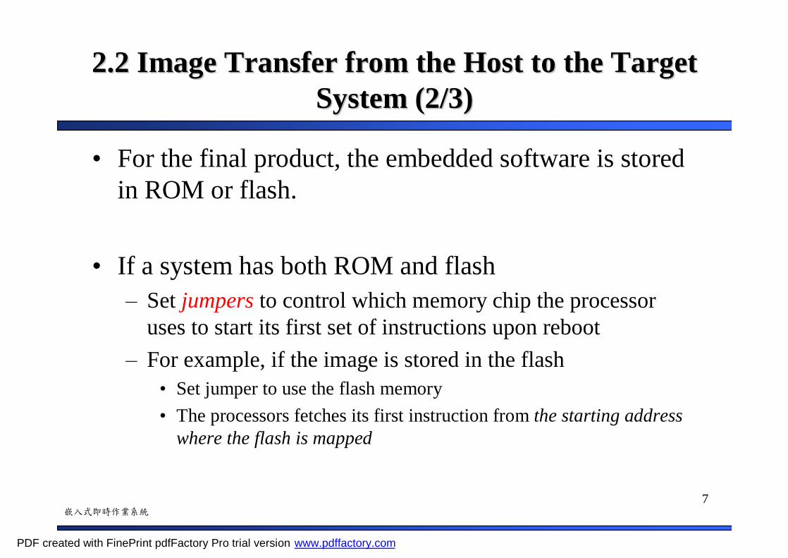
• For the final product, the embedded software is stored in ROM or flash.
• If a system has both ROM and flash– Set jumpers to control which memory chip the processor
uses to start its first set of instructions upon reboot– For example, if the image is stored in the flash
• Set jumper to use the flash memory• The processors fetches its first instruction from the starting address
where the flash is mapped
PDF created with FinePrint pdfFactory Pro trial version www.pdffactory.com
8嵌入式即時作業系統
2.2 Image Transfer from the Host to the Target 2.2 Image Transfer from the Host to the Target System (3/3)System (3/3)
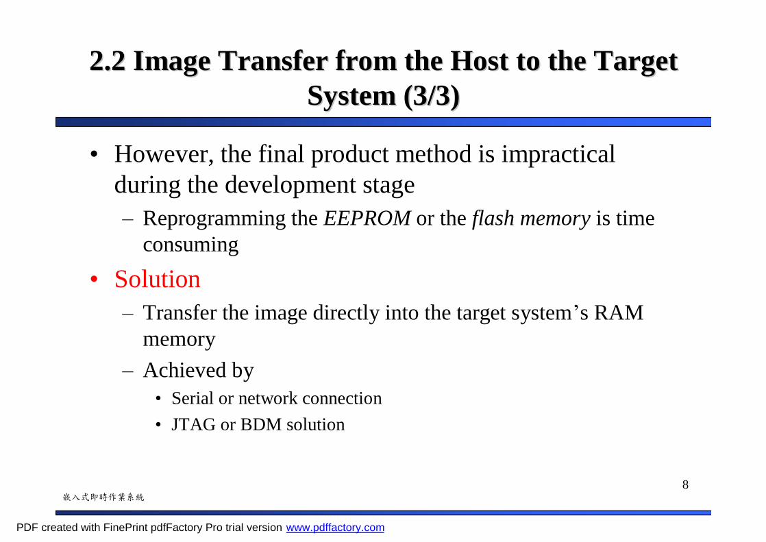
• However, the final product method is impractical during the development stage– Reprogramming the EEPROM or the flash memory is time
consuming• Solution
– Transfer the image directly into the target system’s RAM memory
– Achieved by• Serial or network connection• JTAG or BDM solution
PDF created with FinePrint pdfFactory Pro trial version www.pdffactory.com

9嵌入式即時作業系統
2.3 Target System Tools2.3 Target System Tools
• Embedded Loader
• Embedded Monitor
• Target Debug Agent
PDF created with FinePrint pdfFactory Pro trial version www.pdffactory.com
10嵌入式即時作業系統
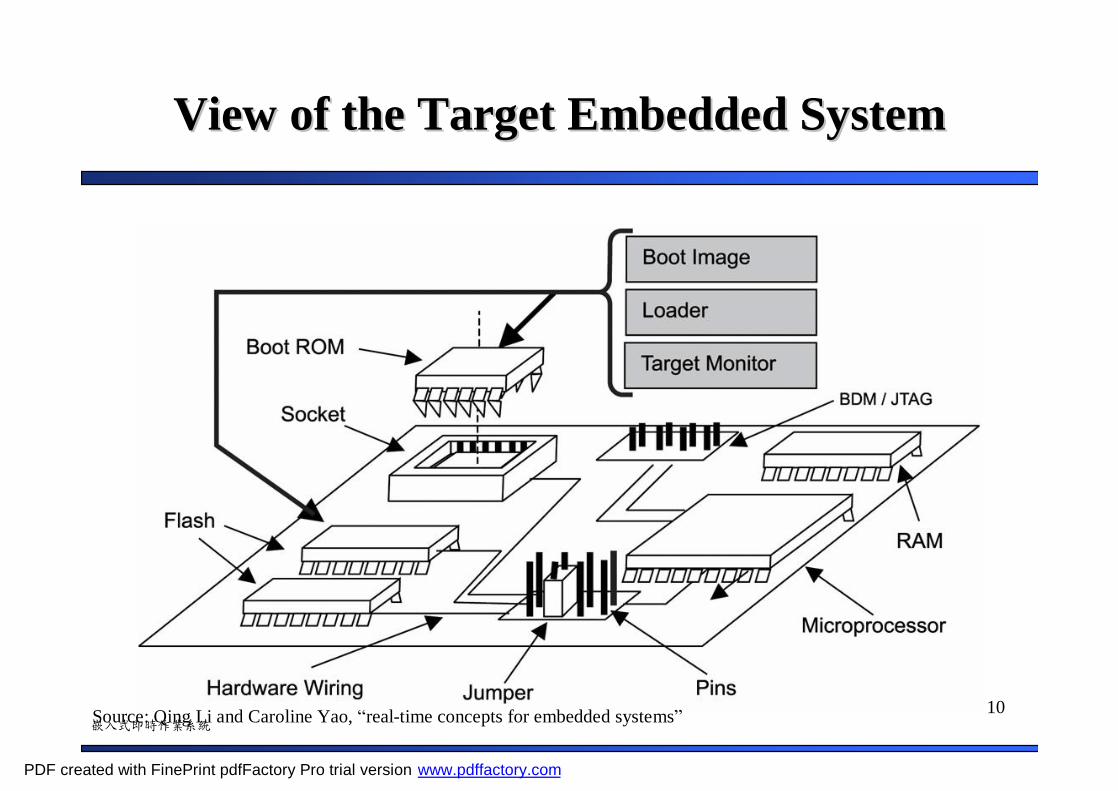
View of the Target Embedded SystemView of the Target Embedded System
Source: Qing Li and Caroline Yao, “real-time concepts for embedded systems”
PDF created with FinePrint pdfFactory Pro trial version www.pdffactory.com
11嵌入式即時作業系統
2.3.1 Embedded Loader (1/3)2.3.1 Embedded Loader (1/3)
• At the early development phase, a common approach is write a loader program for the target and use it to download the image from the host system
• Embedded loader– Download the image from the host system to the target
system– The loader is often programmed into ROM
PDF created with FinePrint pdfFactory Pro trial version www.pdffactory.com
12嵌入式即時作業系統
2.3.1 Embedded Loader (2/3)2.3.1 Embedded Loader (2/3)
• To communicate with the host system to download the image– Require a data transfer protocol and communication parameters between
the host utility and the embedded loader
• Embedded loader may download the image– Either directly to the RAM memory– Or to the flash memory if the loader has the flash programming capability
• After downloading to the flash, must set jumper to execute system from flash
• The downloading medium can be– Serial line– Network connection
• For example, Ethernet and uses FTP or TFTP protocols
PDF created with FinePrint pdfFactory Pro trial version www.pdffactory.com
13嵌入式即時作業系統
2.3.1 Embedded Loader (3/3)2.3.1 Embedded Loader (3/3)
• However, before the loader can execute, there must be a boot image to initialize the target
• Boot image– Part of the ROM chip is occupied by the boot image– Consist of the code that executes when the system powers up
• Initialize the required peripheral devices• Initialize the memory system for downloading the image• Initialize the interrupt controller and install default interrupt handler
– Prepare the system to execute the loader
PDF created with FinePrint pdfFactory Pro trial version www.pdffactory.com

14嵌入式即時作業系統
2.3.2 Embedded Monitor (1/2)2.3.2 Embedded Monitor (1/2)
• An alternative to the boot image plus embedded loaderapproach is to use an embedded monitor
• Furthermore, embedded monitor enable developers to examine and debug the target system at run time
• Thus, an embedded monitor– boot image plus embedded loader– Add the interactive debug capability
PDF created with FinePrint pdfFactory Pro trial version www.pdffactory.com
15嵌入式即時作業系統
2.3.2 Embedded Monitor (2/2)2.3.2 Embedded Monitor (2/2)
• How to provide developer to examine and debug the target system at run time?
• Solution:– Embedded monitor defines a set of commands that can be
accessible through a terminal emulation program over the serial line• Download the image• Read from and write to system memory locations• Read and write system registers• Set and clear different types of breakpoints• Single-step instructions• Reset the system
PDF created with FinePrint pdfFactory Pro trial version www.pdffactory.com
16嵌入式即時作業系統
2.3.3 Target Debug Agent2.3.3 Target Debug Agent
• Target debug agent, or debug agent – Embedded monitor + visual source-level debug capability
for the host debugger• Thus, a target debug agent must provide enough
information for the host debugger to provide visual source-level debug capability
• For example, a debug agent has built-in knowledge of the RTOS objects and services– Allow the developer to explore such object and services
fully and visually
PDF created with FinePrint pdfFactory Pro trial version www.pdffactory.com

17嵌入式即時作業系統
2.4 Target Boot Process2.4 Target Boot Process
• We give an example to show a embedded system boot process– Note that, each embedded system may have its own booting scenario
• Assume– The reset vector is contained in ROM and mapped to 0x00000h
• The code executed when a embedded system powers on• Usually a jump into another part of memory space where the real
initialization code is found– The loader is contained in flash and is mapped to 0x00040h– A loader performs
• System bootstrapping• Image downloading• Initialization
PDF created with FinePrint pdfFactory Pro trial version www.pdffactory.com
18嵌入式即時作業系統
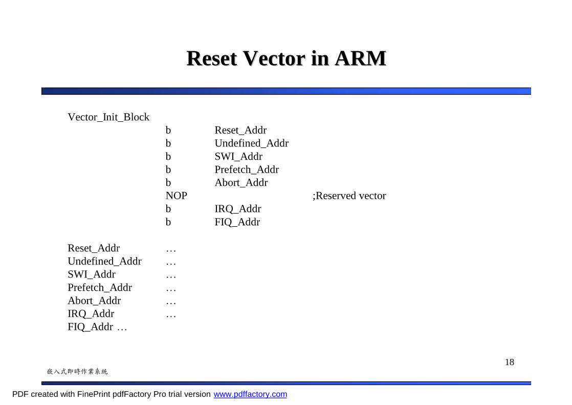
Reset Vector in ARMReset Vector in ARM
Vector_Init_Blockb Reset_Addrb Undefined_Addrb SWI_Addrb Prefetch_Addrb Abort_AddrNOP ;Reserved vectorb IRQ_Addrb FIQ_Addr
Reset_Addr …Undefined_Addr …SWI_Addr …Prefetch_Addr …Abort_Addr …IRQ_Addr …FIQ_Addr …
PDF created with FinePrint pdfFactory Pro trial version www.pdffactory.com

19嵌入式即時作業系統
Example: Bootstrap OverviewExample: Bootstrap Overview
Source: Qing Li and Caroline Yao, “real-time concepts for embedded systems”
PDF created with FinePrint pdfFactory Pro trial version www.pdffactory.com

20嵌入式即時作業系統
Steps of the Example Bootstrap Process (1/3)Steps of the Example Bootstrap Process (1/3)
• Power on or reset– Processor fetch and executes code from 0x00000h
• Reset vector in ROM– The code in reset vector is a jump instruction to 0x00040h
• Loader in flash– The code in loader first initialize hardware to put the system into a
known state• Processor registers are set with default value• Stack pointer is set with the value found in ROM• Disable interrupt• Initializes the RAM memory and the caches• Perform limited hardware diagnostics on those devices needed for its
operation
PDF created with FinePrint pdfFactory Pro trial version www.pdffactory.com
21嵌入式即時作業系統
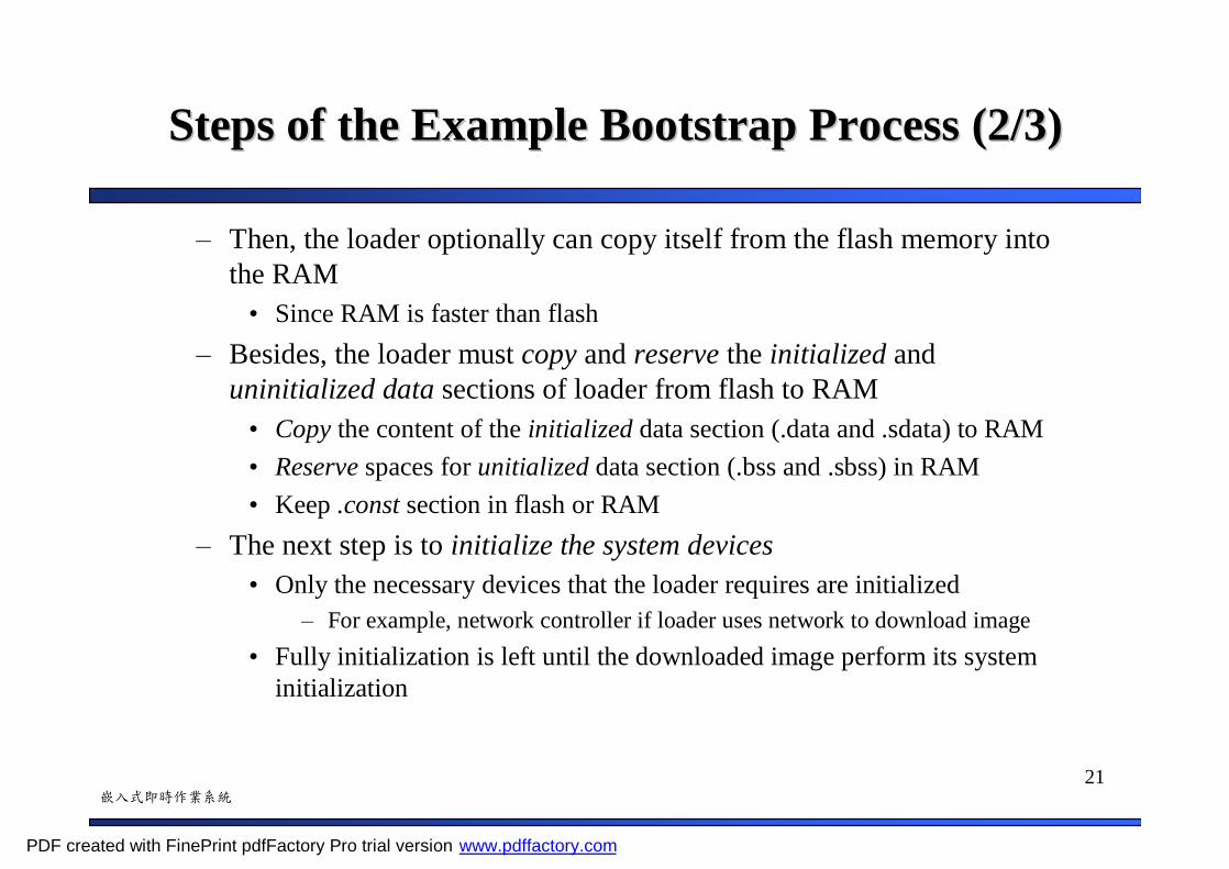
Steps of the Example Bootstrap Process (2/3)Steps of the Example Bootstrap Process (2/3)
– Then, the loader optionally can copy itself from the flash memory into the RAM
• Since RAM is faster than flash– Besides, the loader must copy and reserve the initialized and
uninitialized data sections of loader from flash to RAM • Copy the content of the initialized data section (.data and .sdata) to RAM• Reserve spaces for unitialized data section (.bss and .sbss) in RAM• Keep .const section in flash or RAM
– The next step is to initialize the system devices• Only the necessary devices that the loader requires are initialized
– For example, network controller if loader uses network to download image• Fully initialization is left until the downloaded image perform its system
initialization
PDF created with FinePrint pdfFactory Pro trial version www.pdffactory.com

22嵌入式即時作業系統
Steps of the Example Bootstrap Process (3/3)Steps of the Example Bootstrap Process (3/3)
– Now, the loader can transfer the application image to the target system• Application image: RTOS + kernel + application code• Application image may come from
– Read-only memory devices on the target– The host development system
PDF created with FinePrint pdfFactory Pro trial version www.pdffactory.com
23嵌入式即時作業系統
2.5 Target Image Execution Scenarios2.5 Target Image Execution Scenarios
• Three image execution scenarios– Execute from ROM while using RAM for data
– Execute from RAM after being copied from ROM
– Execute from RAM after being downloaded from a host system
PDF created with FinePrint pdfFactory Pro trial version www.pdffactory.com
24嵌入式即時作業系統
2.5.1 Executing From ROM Using RAM for 2.5.1 Executing From ROM Using RAM for Data (1/2)Data (1/2)
• Execution in Place (XIP)
• Program image executes directly out of ROM– Only act as a boot image optionally plus application code– No loader functionality
• However, the data section must still reside in RAM
PDF created with FinePrint pdfFactory Pro trial version www.pdffactory.com
25嵌入式即時作業系統
2.5.1 Executing From ROM Using RAM for 2.5.1 Executing From ROM Using RAM for Data (2/2)Data (2/2)
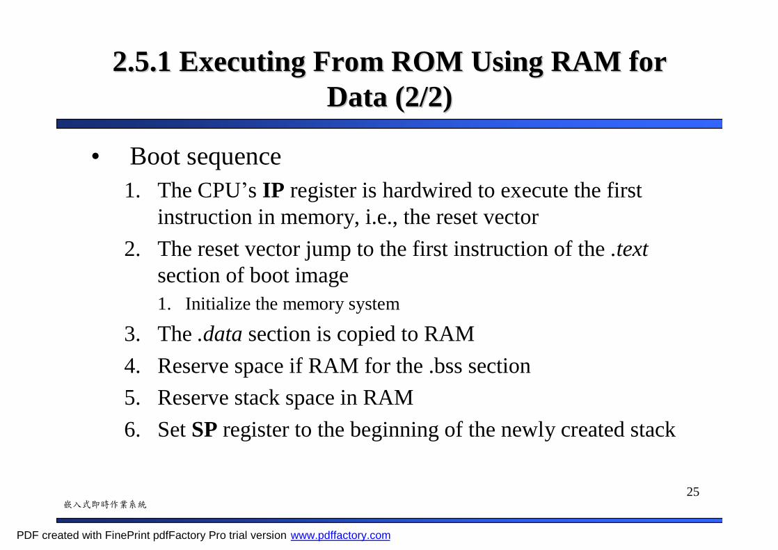
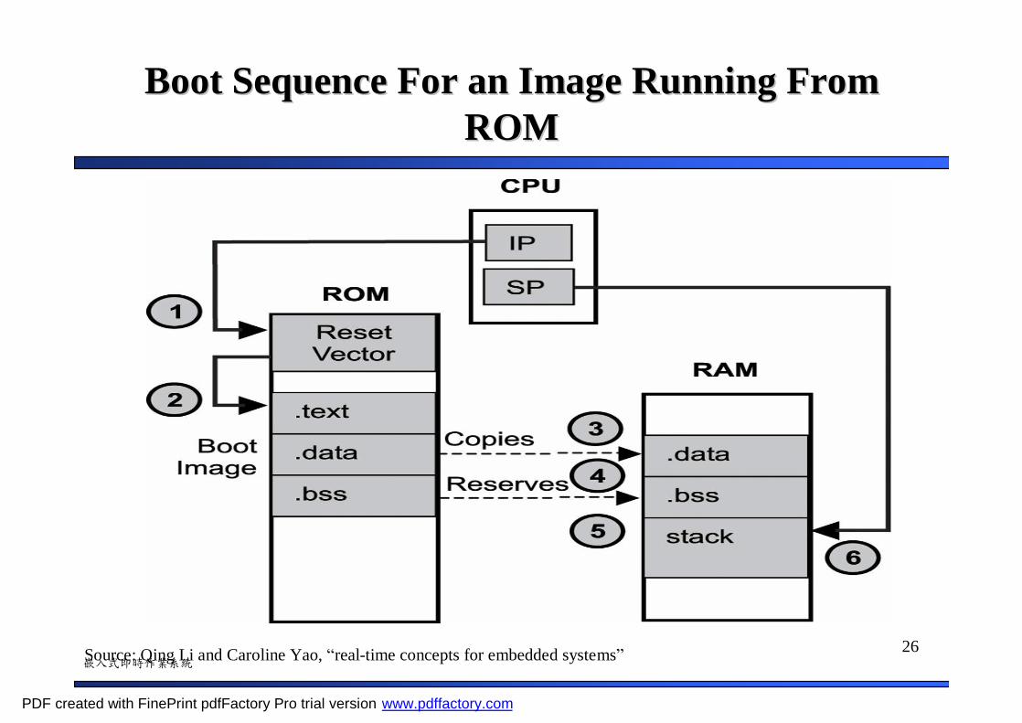
• Boot sequence1. The CPU’s IP register is hardwired to execute the first
instruction in memory, i.e., the reset vector2. The reset vector jump to the first instruction of the .text
section of boot image1. Initialize the memory system
3. The .data section is copied to RAM4. Reserve space if RAM for the .bss section5. Reserve stack space in RAM6. Set SP register to the beginning of the newly created stack
PDF created with FinePrint pdfFactory Pro trial version www.pdffactory.com
26嵌入式即時作業系統
Boot Sequence For an Image Running From Boot Sequence For an Image Running From ROMROM
Source: Qing Li and Caroline Yao, “real-time concepts for embedded systems”
PDF created with FinePrint pdfFactory Pro trial version www.pdffactory.com

27嵌入式即時作業系統
2.5.2 Executing from RAM After Image 2.5.2 Executing from RAM After Image Transfer From ROM (1/2)Transfer From ROM (1/2)
• The boot loader transfers an application image from ROM to RAM for execution– The application image is usually compressed in ROM to
reduce the storage space required
PDF created with FinePrint pdfFactory Pro trial version www.pdffactory.com
28嵌入式即時作業系統
2.5.2 Executing from RAM After Image 2.5.2 Executing from RAM After Image Transfer From ROM (2/2)Transfer From ROM (2/2)
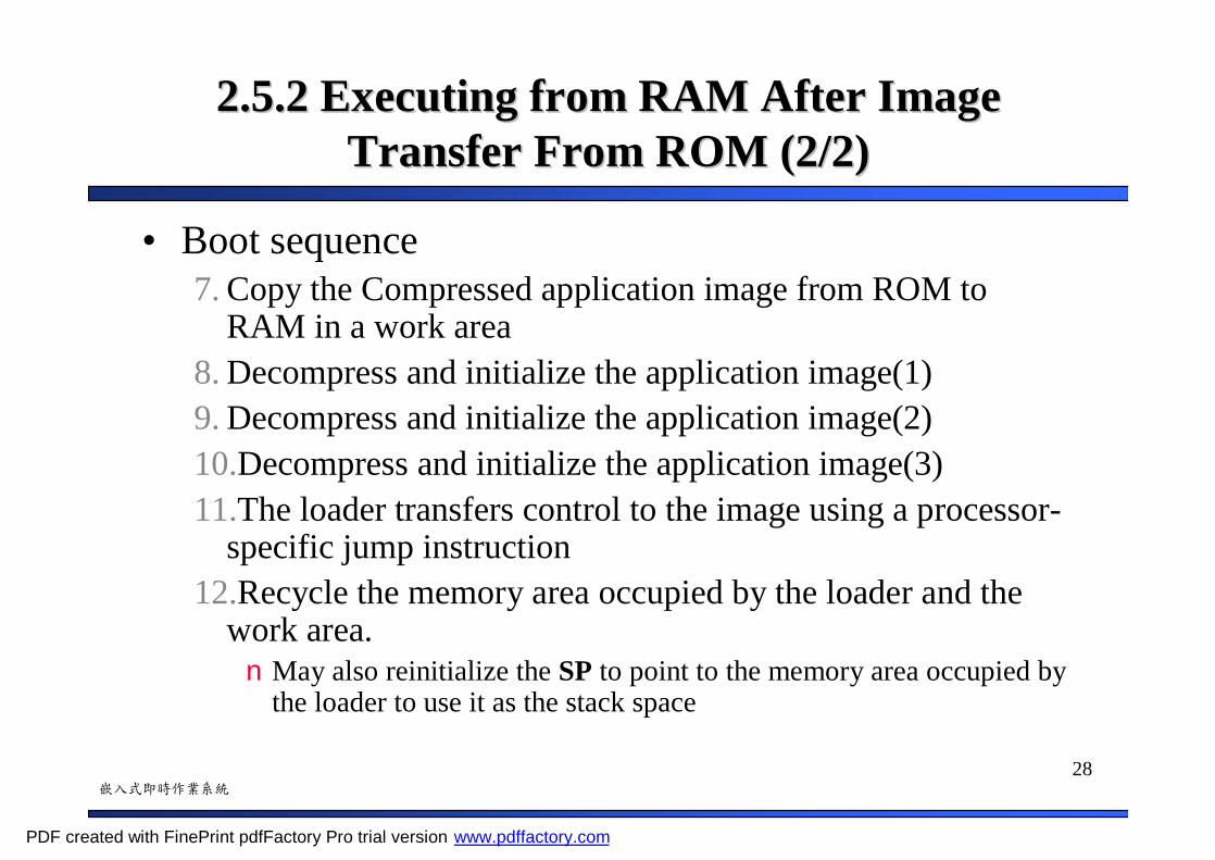
• Boot sequence7. Copy the Compressed application image from ROM to
RAM in a work area8. Decompress and initialize the application image(1)9. Decompress and initialize the application image(2)10.Decompress and initialize the application image(3)11.The loader transfers control to the image using a processor-
specific jump instruction12.Recycle the memory area occupied by the loader and the
work area. nMay also reinitialize the SP to point to the memory area occupied by
the loader to use it as the stack space
PDF created with FinePrint pdfFactory Pro trial version www.pdffactory.com

29嵌入式即時作業系統
Boot Sequence For an Image Executing From Boot Sequence For an Image Executing From RAM after Transfer From ROMRAM after Transfer From ROM
Source: Qing Li and Caroline Yao, “real-time concepts for embedded systems”
PDF created with FinePrint pdfFactory Pro trial version www.pdffactory.com

30嵌入式即時作業系統
2.5.3 Executing from RAM After Image 2.5.3 Executing from RAM After Image Transfer From ROM Transfer From ROM
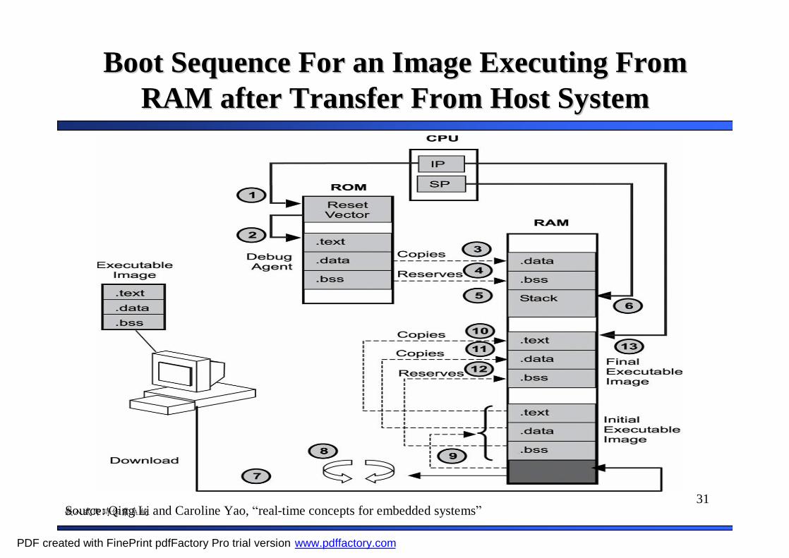
• Boot sequence7. The application image is downloaded from the host
development system8. The image integrity is verified9. The image is decompressed if necessary10-12. The debug agent loads the image section into their
respective run address in RAM13. The debug agent transfers control to the download image
PDF created with FinePrint pdfFactory Pro trial version www.pdffactory.com
31嵌入式即時作業系統
Boot Sequence For an Image Executing From Boot Sequence For an Image Executing From RAM after Transfer From Host SystemRAM after Transfer From Host System
Source: Qing Li and Caroline Yao, “real-time concepts for embedded systems”
PDF created with FinePrint pdfFactory Pro trial version www.pdffactory.com

32嵌入式即時作業系統
2.6 Target System Software Initialization 2.6 Target System Software Initialization Sequence (1/2)Sequence (1/2)
• Target image may consists– Board support package (BSP)
• A full spectrum of drivers for the hardware components/devices
– RTOS– Other embedded modules
• File system, networking…
– Application
PDF created with FinePrint pdfFactory Pro trial version www.pdffactory.com
33嵌入式即時作業系統
2.6 Target System Software Initialization 2.6 Target System Software Initialization Sequence (2/2)Sequence (2/2)
• Example: a target image structured in the following slide
• Then, the main steps to initialize the system– Hardware initialization– RTOS initialization– Application initialization
PDF created with FinePrint pdfFactory Pro trial version www.pdffactory.com

34嵌入式即時作業系統
Software Components of a Target ImageSoftware Components of a Target Image
Source: Qing Li and Caroline Yao, “real-time concepts for embedded systems”
PDF created with FinePrint pdfFactory Pro trial version www.pdffactory.com
35嵌入式即時作業系統
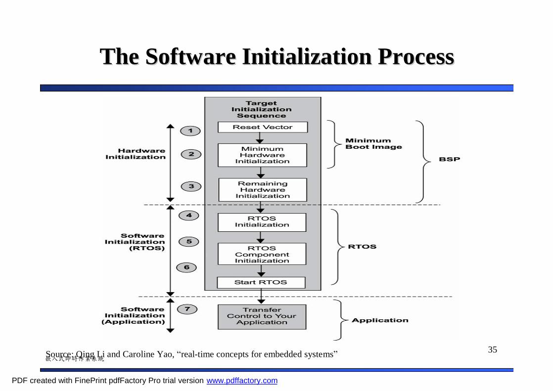
The Software Initialization ProcessThe Software Initialization Process
Source: Qing Li and Caroline Yao, “real-time concepts for embedded systems”
PDF created with FinePrint pdfFactory Pro trial version www.pdffactory.com
36嵌入式即時作業系統
2.6.1 Hardware Initialization (1/3)2.6.1 Hardware Initialization (1/3)
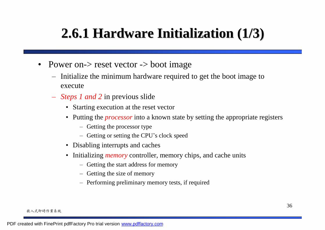
• Power on-> reset vector -> boot image– Initialize the minimum hardware required to get the boot image to
execute– Steps 1 and 2 in previous slide
• Starting execution at the reset vector• Putting the processor into a known state by setting the appropriate registers
– Getting the processor type– Getting or setting the CPU’s clock speed
• Disabling interrupts and caches• Initializing memory controller, memory chips, and cache units
– Getting the start address for memory– Getting the size of memory– Performing preliminary memory tests, if required
PDF created with FinePrint pdfFactory Pro trial version www.pdffactory.com

37嵌入式即時作業系統
2.6.1 Hardware Initialization (2/3)2.6.1 Hardware Initialization (2/3)
• Then – Boot sequence may copy and decompress the sections of
code to RAM– It must copy and decompress its data to RAM
• Finally, initialize other hardware components– Step 3 in previous slide
• Setting up execution handlers• Initializing interrupt handlers• Initializing bus interfaces, such as PCI, USB…• Initializing board peripherals such as serial, LAN and SCSI
PDF created with FinePrint pdfFactory Pro trial version www.pdffactory.com

38嵌入式即時作業系統
2.6.1 Hardware Initialization (3/3)2.6.1 Hardware Initialization (3/3)
• Initial boot sequence– Steps 1 and 2– Mainly initialize the CPU and memory subsystem
• BSP initialization phase– Also called hardware initialization– Steps 1 to 3
PDF created with FinePrint pdfFactory Pro trial version www.pdffactory.com

39嵌入式即時作業系統
Example: Hardware Initialization in an ARMExample: Hardware Initialization in an ARM--Based Embedded SystemBased Embedded System
• After reset or power on, the instruction located at address 0x0 must transfer control to the initialization code– Set up exception vectors– Initialize the memory system– Initialize the stack pointer registers– Change processor mode if necessary– Change processor state if necessary
• Note, the state of ARM processor cores after reset is– SVC mode– interrupts disabled– ARM state.
PDF created with FinePrint pdfFactory Pro trial version www.pdffactory.com
40嵌入式即時作業系統
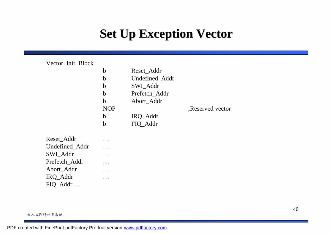
Set Up Exception VectorSet Up Exception Vector
Vector_Init_Blockb Reset_Addrb Undefined_Addrb SWI_Addrb Prefetch_Addrb Abort_AddrNOP ;Reserved vectorb IRQ_Addrb FIQ_Addr
Reset_Addr …Undefined_Addr …SWI_Addr …Prefetch_Addr …Abort_Addr …IRQ_Addr …FIQ_Addr …
PDF created with FinePrint pdfFactory Pro trial version www.pdffactory.com

41嵌入式即時作業系統
Initialize the Memory SystemInitialize the Memory System
• --- Perform ROM/RAM remapping, if requiredIF :DEF: ROM_RAM_REMAP
• --- Initialize memory systemIF :DEF: CACHE
IMPORT Clock_SpeedIMPORT Cache_InitBL Clock_SpeedBL Cache_Init
ENDIF
PDF created with FinePrint pdfFactory Pro trial version www.pdffactory.com
42嵌入式即時作業系統
Initialize the Stack PointerInitialize the Stack Pointer
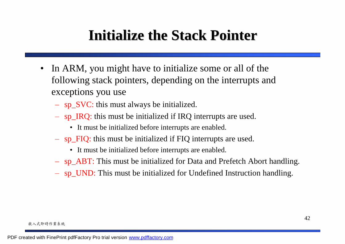
• In ARM, you might have to initialize some or all of the following stack pointers, depending on the interrupts and exceptions you use– sp_SVC: this must always be initialized.– sp_IRQ: this must be initialized if IRQ interrupts are used.
• It must be initialized before interrupts are enabled.– sp_FIQ: this must be initialized if FIQ interrupts are used.
• It must be initialized before interrupts are enabled.– sp_ABT: This must be initialized for Data and Prefetch Abort handling.– sp_UND: This must be initialized for Undefined Instruction handling.
PDF created with FinePrint pdfFactory Pro trial version www.pdffactory.com
43嵌入式即時作業系統
Initialize the Stack PointerInitialize the Stack Pointer
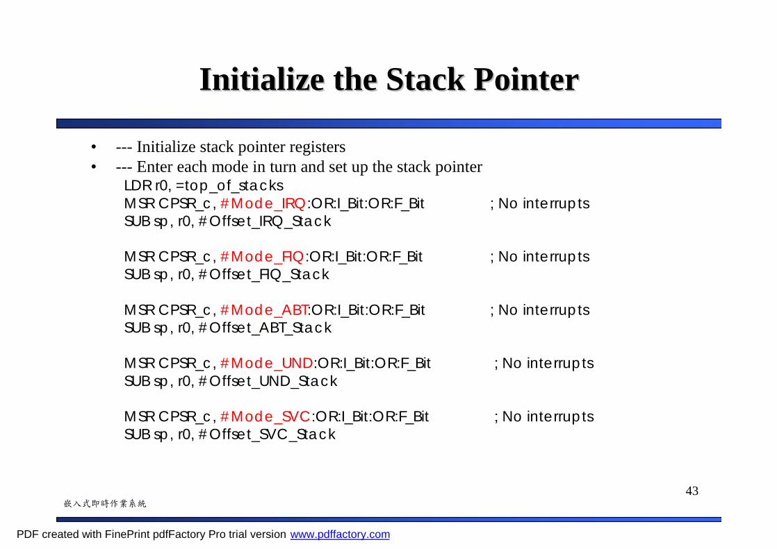
• --- Initialize stack pointer registers• --- Enter each mode in turn and set up the stack pointer
LDR r0, =top_of_stacksMSR CPSR_c, #Mode_IRQ:OR:I_Bit:OR:F_Bit ; No interruptsSUB sp, r0, #Offset_IRQ_Stack
MSR CPSR_c, #Mode_FIQ:OR:I_Bit:OR:F_Bit ; No interruptsSUB sp, r0, #Offset_FIQ_Stack
MSR CPSR_c, #Mode_ABT:OR:I_Bit:OR:F_Bit ; No interruptsSUB sp, r0, #Offset_ABT_Stack
MSR CPSR_c, #Mode_UND:OR:I_Bit:OR:F_Bit ; No interruptsSUB sp, r0, #Offset_UND_Stack
MSR CPSR_c, #Mode_SVC:OR:I_Bit:OR:F_Bit ; No interruptsSUB sp, r0, #Offset_SVC_Stack
PDF created with FinePrint pdfFactory Pro trial version www.pdffactory.com
44嵌入式即時作業系統
Change the Processor ModeChange the Processor Mode
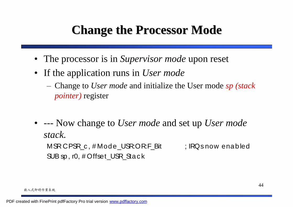
• The processor is in Supervisor mode upon reset• If the application runs in User mode
– Change to User mode and initialize the User mode sp (stack pointer) register
• --- Now change to User mode and set up User mode stack.MSR CPSR_c, #Mode_USR:OR:F_Bit ; IRQs now enabledSUB sp, r0, #Offset_USR_Stack
PDF created with FinePrint pdfFactory Pro trial version www.pdffactory.com
45嵌入式即時作業系統
Change the Processor StateChange the Processor State
• ARM cores start up in ARM state on reset.– The initialization code, at least the reset handler, must be
ARM code.
• If the application is compiled for Thumb– Changing processor state from ARM to Thumb
PDF created with FinePrint pdfFactory Pro trial version www.pdffactory.com
46嵌入式即時作業系統
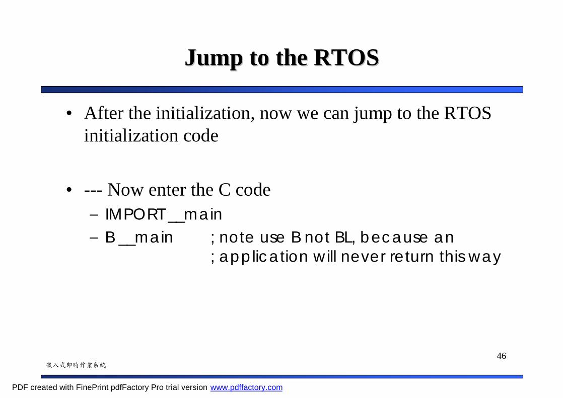
Jump to the RTOSJump to the RTOS
• After the initialization, now we can jump to the RTOS initialization code
• --- Now enter the C code– IMPORT __main– B __main ; note use B not BL, because an
; application will never return this way
PDF created with FinePrint pdfFactory Pro trial version www.pdffactory.com
47嵌入式即時作業系統
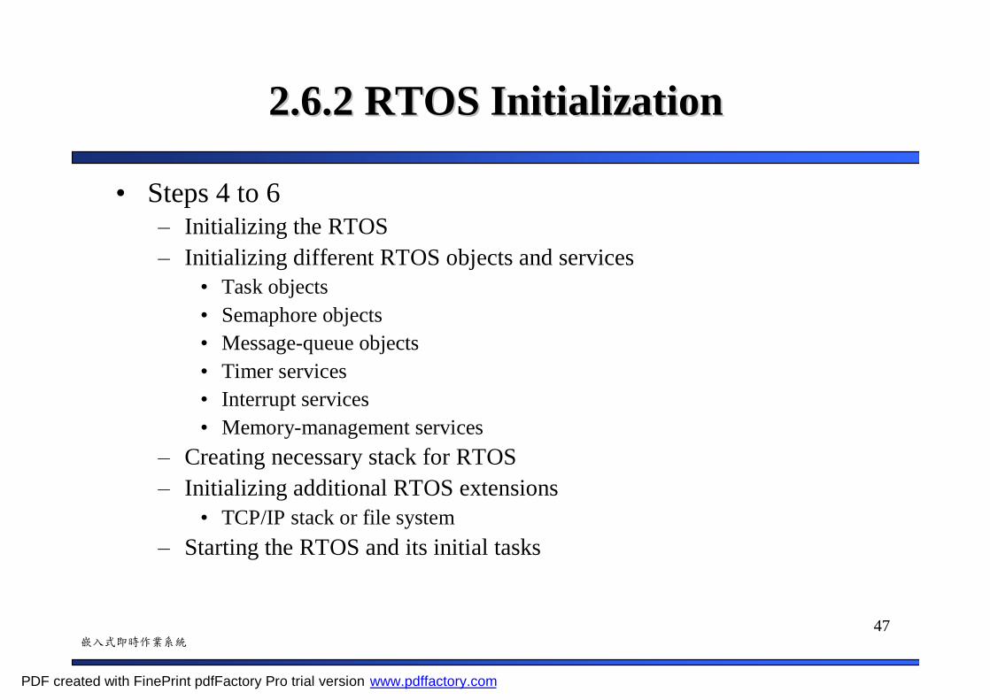
2.6.2 RTOS Initialization2.6.2 RTOS Initialization
• Steps 4 to 6– Initializing the RTOS– Initializing different RTOS objects and services
• Task objects• Semaphore objects• Message-queue objects• Timer services• Interrupt services• Memory-management services
– Creating necessary stack for RTOS– Initializing additional RTOS extensions
• TCP/IP stack or file system– Starting the RTOS and its initial tasks
PDF created with FinePrint pdfFactory Pro trial version www.pdffactory.com

48嵌入式即時作業系統
Example: Example: LyraOSLyraOS InitializationInitialization
void __main(caddr_t addr, size_t npg){
pthread_t thread_id;
addr = (void *)((int)(addr + MM_PAGE_SIZE - 1) & ~(MM_PAGE_SIZE - 1));page_init(addr, npg);init_timer();pthread_init();irq_enable();
msginit();
start_application();}
PDF created with FinePrint pdfFactory Pro trial version www.pdffactory.com
49嵌入式即時作業系統
2.6.3 Application Software Initialization2.6.3 Application Software Initialization
• Finally, transfer control to the application– RTOS calls a predefined function implemented by the
application
– Then, the application software goes through its initialization• Declared and implemented necessary objects, services, data
structures, variables, and other constructs
PDF created with FinePrint pdfFactory Pro trial version www.pdffactory.com

50嵌入式即時作業系統
ReferenceReference
• Qing Li and Caroline Yao, “Real-Time Concepts for Embedded Systems”, CMP Books, ISBN: 1-57820-124-1, 2003
• ARM Developer Suite: Developer Guide, ARM Limited.• C. H. Lee, D. W. Chang, H. P. Chang, and R. C. Chang , “An
Embedded Operating System : LyraOS,” Technical Report, National Chiao Tung University, 2002
• Steve B. Furber, “ARM System-on-Chip Architecture,”Addison-Wesley, 2000
PDF created with FinePrint pdfFactory Pro trial version www.pdffactory.com

51嵌入式即時作業系統
ReferenceReference
• Giorgio C. Buttazzo, “Hard Real-Time Computing Systems: Predictable Scheduling Algorithms and Applications,” Kluwer Academic Publishers, 1997
• Jane W. S. Liu, “Real-Time Systems,” Prentice Hall, 2002
PDF created with FinePrint pdfFactory Pro trial version www.pdffactory.com


![Embedded Systems Chapter -7 Control Systemaakritsubedi9.com.np/files/Chapter 7 Embedded... · Embedded Systems Chapter -7 Control System. 7.Control System [3 Hrs.] 7.1 Open-loop and](https://img.dokumen.tips/doc/110x75/5f0a9eb27e708231d42c867b/embedded-systems-chapter-7-control-7-embedded-embedded-systems-chapter-7.jpg)