Embed Size (px)
Citation preview


Chapter 2:
Strain
Chapter 3:
Torsion
Chapter 4:Shear andMoment Diagram

Strain - Is defined as change in length per unit length,
simply put it is unit deformation
L

Stress and Strain
Exist concurrently in nature; if a body is under stress, it also
exhibits strain.
Considering a typical tensile strength test on a steel
reinforcing bar, the following diagram is produced

STRESS VERSUS STRAIN
Yield Point
Ultimate Strength
Rupture Strength
ActualRupture Strength
Elastic LimitProportional Limit
Stress,
Strain,O

For the strain to be assumed constant and for the average
value to be representative of the whole, the following
conditions must be met:
1. Specimen must be of constant cross section.
2. Material must be homogeneous.
3. Load must be axial and constant.

Hooke’s Law: Axial Deformation
Within the region up to the elastic limit, a material is said to behave
elastically. Beyond which, the material behaves plastically.
Yield Point
Ultimate Strength
Rupture Strength
ActualRupture Strength
Elastic LimitProportional Limit
Stress,
Strain,O

Within the proportional limit, stress and strain varies linearly, that
is, stress is proportional to strain.
Derivation:

Example : An aluminum bar having a cross-sectional area
of 160 mm2 carries the axial loads at the positionsshown in the figure. If E = 70 x 103 MPa, compute thetotal deformation of the bar. Assume that the bar issuitably braced to prevent buckling.
0.8 m 1.0m 0.6m
35 kN 15 kN 30 kN10 kN

Example : An aluminum bar having a cross-sectional area
of 160 mm2 carries the axial loads at the positionsshown in the figure. If E = 70 x 103 MPa, compute thetotal deformation of the bar. Assume that the bar issuitably braced to prevent buckling.
0.8 m 1.0m 0.6m
35 kN15 kN 30 kN10 kN

Example : An aluminum bar is fastened between a steel rod
and a bronze rod as shown. Axial loads are applied atthe positions indicated. Assume that the assembly issuitably braced to prevent buckling and that Es = 200 x103 MPa, Ea = 70 x 103 MPa, and Eb = 83 x 103 MPa. Findthe value of the force acting on each of the rod so thatit will not exceed a maximum overall deformation of 2mm or a stress of 120 MPa, 140 MPa and 80 MPa,respectively.
P3P 2P
BronzeA = 450 mm2
AluminumA = 600 mm2
SteelA = 300 mm2
0.6m 1.0m 0.8m
4P
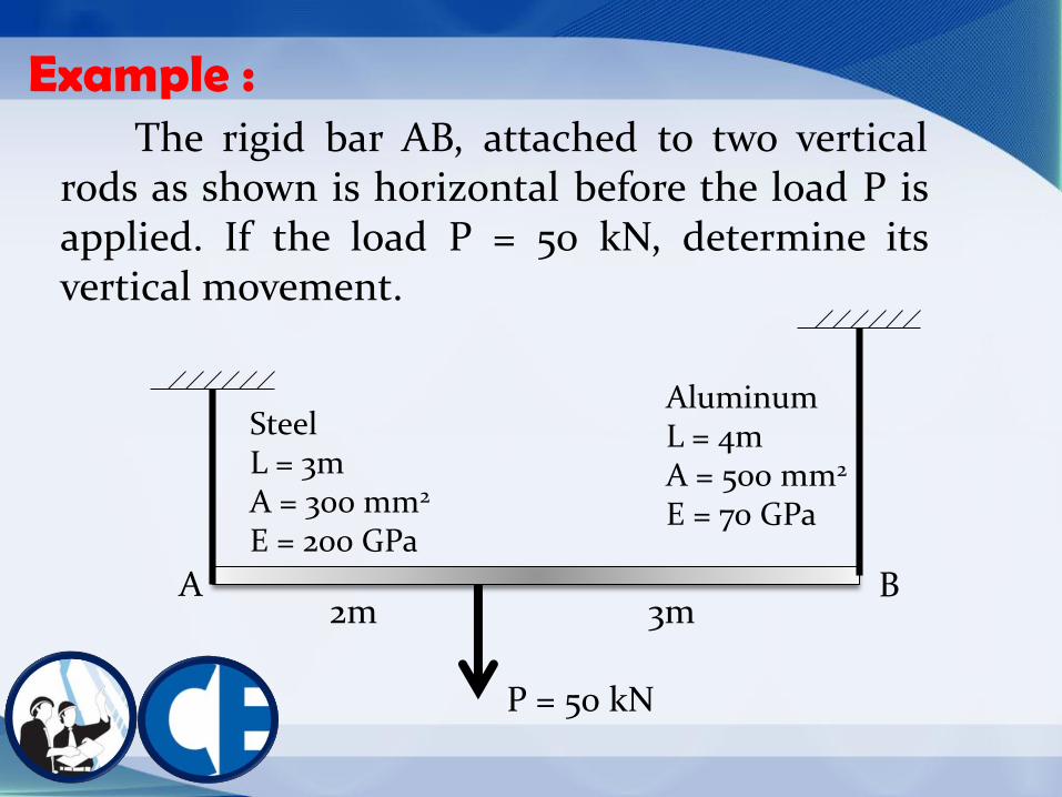
Example : The rigid bar AB, attached to two vertical
rods as shown is horizontal before the load P isapplied. If the load P = 50 kN, determine itsvertical movement.
A
P = 50 kN
B
AluminumL = 4mA = 500 mm2
E = 70 GPa
SteelL = 3mA = 300 mm2
E = 200 GPa
2m 3m

Example : Two aluminum rods AB and BC, hinged to rigid
supports, are pinned together at B to carry a verticalload P = 20 kN. If each rod has a cross-sectional areaof 400 mm2 and E = 70 x 103 MPa, compute theelongation of each rod and
the horizontal and vertical
displacements of point B.
Assume = 30o and
=300
3m
2m
A
B
CP = 20 kN

Example : A round bar of length 10m tapers uniformly
from a diameter 100 mm at one end to a smallerdiameter 30 mm at the other. Determine theelongations caused by an axial tensile load P = 50kN.
100 mm30mm
P

Example : A rod is composed of three segments and
carries the axial loads P1 = 120 kN and P2 = 50 kN.Determine the stress in each material if the walls arerigid.
BronzeA = 2400 mm2
E = 83 GPa
AluminumA = 1200 mm2
E = 70 GPa
SteelA = 600 mm2
E = 200 GPa
0.6m 0.4m 0.3 m
P1 P2

Example : A rod is composed of three segments and
carries the axial loads P1 = 100 kN and P2 = 60 kN.Determine the stress in each material if the left wallyields 0.60 mm.
BronzeA = 2400 mm2
E = 83 GPa
AluminumA = 1200 mm2
E = 70 GPa
SteelA = 600 mm2
E = 200 GPa
0.6m 0.4m 0.3 m
P1 P2

Example : A rigid beam with negligible mass is pinned at
one end and supported by two rods. The beam wasinitially horizontal before the load P was applied.Find the vertical movement of P if P = 120 kN.
A
P = 120 kN
AluminumL = 4mA = 500 mm2
E = 70 GPa
SteelL = 3mA = 300 mm2
E = 200 GPa
2m 1m3m

Example : Three rods, each with an area of 300 mm2,
jointly support the load of 10 kN, as shown.Assuming there was no slack or stress in the rodsbefore the load was applied, find the stress in eachrod. Est = 200 GPa and Ebr = 83 GPa.
BronzeBronze
Steel3m
300300
10 kN

Example : A rigid block of mass M is supported by three
symmetrically spaced rods as shown in the figure.Each copper rod has an area of 900 mm2; E = 120GPa; and the allowable stress is 70 MPa. The steelrod has an area of 1200 mm2; E = 200 GPa; and theallowable stress is 140 MPa. Determine the largestmass M which can be supported.
M
Copper160 mm
Copper160 mm
Steel240 mm

Example : A rigid platform in the figure has negligible
mass and rests on two aluminum bars, each 250 mmlong. The center bar is steel and is 249.90 mm long.Find the stress in the steel bar after the center load P= 400 kN is applied. Each aluminum bar has an areaof 1200 mm2 and E = 70 GPa. The steel bar has anarea of 2400 mm2 and E = 200 GPa.
P = 400 kN
Aluminum250 mm
Steel249.9
mm
Aluminum250 mm

Example : As shown in the figure, a rigid beam with
negligible mass is pinned at O and supported by tworods, identical except for length. If P = 30 kN. Findthe (a) load in A, (b) load in B and if rod A elongatesby 2 mm, (c) how much elongation of rod B? (d)Vertical movement of P.
2m 2m 1.5m
P = 30 kN L = 1.5 m
L = 2 m
B
A
O