Embed Size (px)
Citation preview

CHAPTER 2
Single- and Three-Phase Power
1

Objective
-Understand the difference between time and the phasor domains.
-Explain the magnitude and angular relation between the phase and
line voltages in a WYE and DELTA systems.
-Calculate real, reactive, and apparent power in single-phase and
three-phase circuits.
-Define power factor.
-Solve power factor correction problems
2

Review
The total energy delivered to a load divided by the time
required to deliver it yields the average power delivered
Efficiency of the delivered powerEfficiency of the system
Units: horsepower, watts
1 Watt = 1 Joule delivered in a 1 second pulse
3

DC power
DC system:
- Power delivered to the
load does not fluctuate.
- If the transmission line
is long power is lost in
the line.
Important:
-Inductors become short circuits to DC.
-Capacitors become open circuits to DC.
4

Single-Phase AC Circuits
Alternating current derives its name from the fact that the voltage and current are
sinusoidal functions.
Related to the peak value is the the RMS of the waveform.
RMS is found by taking the square root of the mean of the
waveform squared:
The RMS is effective value of the AC voltage or current : the RMS current or voltage is the value that would cause
the same amount of heat in a resistor as a DC current or voltage with the same value.
For sinusoidal functions:
5

Phasors
Convenient way to represent voltages and currents using phasor form (work in phasor domain)
In its simplest form, a phasor can be thought as a complex number that has magnitude and
phase of a sinusoidal function and can be represented partially as a vector in the complex
plane.
IMPORTANT: The magnitude of a phasor will always be RMS value of the sinusoid it is
representing.
Voltage phasor magnitude
Current phasor magnitude; current is lagging the voltage by 30 degrees
6

Example:
a. Choose the voltage as the reference
phasor:current lags the voltage by 30 degrees,
so current phasor will be 30 degrees
behind the voltage
b. Choose the current as the reference
phasor:
current lags the voltage by 30 degrees,
so the voltage phasor will be
+30 degrees
c. Choose the cosine function as the
reference phasor:The sine function lags the cosine by 90
degrees, thus the voltage phasor should be at
-90 degrees, current must be 30 degrees
behind the voltage, so it is at -120 degrees.
Example
7

Symbol notation for several complex
quantities
8

Mathematical operations with phasors
Conversion between rectangular and polar coordinates
Phasor with magnitude “A” and angle alpha
9

Addition of complex numbers:
10

Multiplication of phasors:
Division of phasors:
Example
Conjugate:
11

Impedance in AC Circuits
Impedance of the inductor:
NOTE: 1. There is a phase shift between the voltage and the
current. The current is lagging the voltage by 90
degrees for the inductor.
2. The RMS of the current is the RMS of the voltage
divided by (wL)
Use Ohm’s low in the phasor domain for the
inductor by defining the inductive reactance
Current in the inductor:
Impedance of the inductor:
12
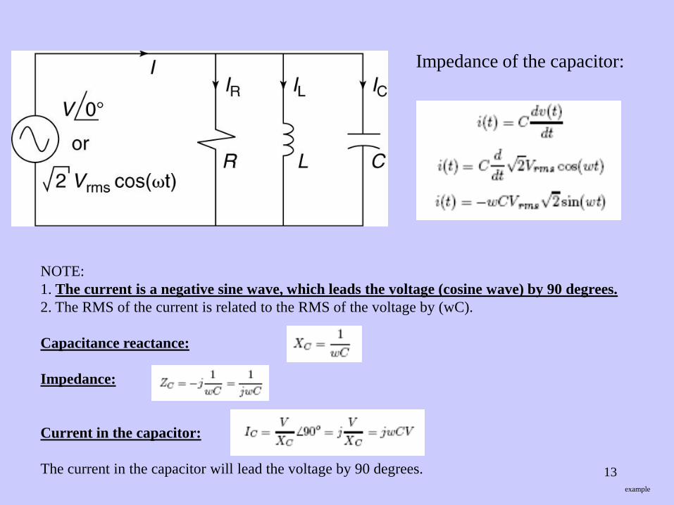
Impedance of the capacitor:
NOTE:
1. The current is a negative sine wave, which leads the voltage (cosine wave) by 90 degrees.
2. The RMS of the current is related to the RMS of the voltage by (wC).
Capacitance reactance:
Impedance:
Current in the capacitor:
The current in the capacitor will lead the voltage by 90 degrees.
example
13

Power in Single-Phase AC Circuits
Real Power (Active Power) energy consumed by the
load that is converted to heat and is not be returned
to its initial stage.
Real power used by the resistor:
Reactive power (Inductor)
Instantaneous current through the inductor varies
sinusoidally.
Inductor stores energy as a function of the current,
thus magnetic field varies with time.
As current increases the inductor stores more energy
in its magnetic field and the power flows from the
source to the inductor.
As current decreases the inductor releases energy back
to the source.
The inductor does not use any power on average, there is
energy moving back and forth between the source and the
Inductor. This is called REACTIVE POWER.
Reactive power (Capacitor)
Voltage across the capacitor varies sinusoidally.
Capacitor stores energy as a function of the voltage,
thus capacitor’s electric field varies with time.
Capacitor draws energy from the source as it charges,
and returns energy as it discharges.
The voltage across the capacitor and the current through the
inductor are 90 degrees out of phase, thus when inductor is
charging the capacitor discharges.
14
example

Complex Power
Real power
Reactive power
Magnitude of the complex (apparent )
power
Relationship between the real and apparent
power.
Power factor
Angle theta is the angle of the current with
respect to the voltage.
If the current lags the voltage (inductive load)
then theta is negative.
If the current leads the voltage (capacitive load)
then theta is positive.
Power factor is always positive and less than 1.
Relationship between the reactive and apparent
power.
15
example

Instantaneous AC Power
Resistive load.
Voltage and current both have a peak value of 1.0 and RMS of 0.707.
The apparent power
Since the voltage and current are always in phase, their product is always positive and, so power always flows
from the source to the resistive load.
In this case the angle between the voltage and the current is zero so the power factor ( = cos (angle)) is unity.
Shows instantaneous
voltage, current and
power for a resistive
load
16
example

Resistive-inductive (R-L) load
Shows instantaneous
voltage, current and
power for a resistive-
inductive load
Current lags the voltage by 60 degrees.
Since the voltage and current are out of phase their product may be negative and as a result there are times
when the instantaneous power is negative. This represents a return of energy from the load to the source.
That energy comes from the magnetic field of the system inductance.
Apparent power is 0.5 VA
Average power is 0.25 W=0.5cos (60)
Power factor
17

Purely inductive load.
Shows instantaneous
voltage, current and
power for a purely
inductive load
Current lags the voltage by 90 degrees.
Instantaneous power has an average of zero. Energy flows from source to the load half of the time and from the load
back to the source the other half of the time.
Apparent power is 0.5 VA.
Real power is zero.
Reactive power is 0.5 Volt-Amperes-Reactive=0.5sin(90)
Power factor18

Three-Phase AC Circuits
Most industrial and commercial electrical power systems employ a 3-phase configuration.
3-phase systems consist of 3 equal in magnitude voltages and 120 degrees out of phase relative
to each other.
Example: 3-phase generator contains coils that are physically spaced 120 degrees apart and when the rotor turns,
the voltages induced in the coils are electrically 120 degrees apart.
The power flowing in 3-phase system has a constant value19
example

Three-Phase WYE Configuration
Wye:
Consists of three load components connected with
a common point called neutral.
Line-to-neutral, phase-to-neutral, branch voltage or
simply phase voltage :
the voltage between each phase (line or hot)
conductor and the neutral,
Lin-to-line or simply line voltage :
the voltage between any two conductors,
Advantage of 3-phase Wye configuration: availability
of two voltage levels.
Common system voltages: 277/480 and 120/208V.
20

Three-Phase DELTA Configuration
Delta:
Consists of three load components connected end-
to-end way and has no neutral point. Phases are
connected in a triangle.
The vertices of the triangle are connected to the
power system and the current that flows on those
conductors is called the line current :
The current flowing in the branches, which are
connected between the lines, is called the phase
current :
Common system voltages: 240V and 480V.
21

Angular relationship between VL and VP
Positive ABC phase sequence (phasors are assumed to rotate in the counterclockwise direction)
Assume the reference voltage and with positive phase sequence
Using Wye circuit we write equations around one of the loops according to the Kirchoff's law:
Since and have the same magnitude and separated by 120 degrees we can write:
Adding two phasors we get:
The line voltage leads the phase voltage by 30 degrees and the line voltage is the √3 larger in magnitude
than the phase voltage. 22

Angular relationship between IL and IP
The angular relationship between the line and phase current in a delta system
and the relationship of their magnitudes:
The line current lags the phase current by 30 degrees, assuming a standard ABC
phase rotation, and the line current is √3 larger in magnitude than the phase current
23

Balanced and unbalanced 3-Phase systems
A balanced system is one in which the line and phase currents and voltages in all three phases
are equal in magnitude and separated by 120 degrees, and the impedances in all three phases
are identical.
An unbalanced system is one in which any of the foregoing requirements are not met.
Power calculation in balanced 3-phase systems:
WYE system Delta system
For a single-phase system, the apparent power is the product of the phase voltage and phase current
For a balanced 3-phase system , the total 3-phase apparent power is three times the power consumed by one phase
24examples
Power Factor Correction
Power factor is the ratio of real and to apparent power.
It is a measure of how effectively the current is being converted into useful work output.
Most AC electrical power systems supply loads that are both resistive and reactive.
Power source delivers real power to the resistive component of the load and this real power
is converted into the useful work.
The power source must also deliver reactive power to the reactive components of the load.
Reactive power does no useful work and is alternatively stored in the reactive elements of the load.
Although reactive power does no useful work, the source must have sufficient capacity to provide
the reactive power, and the distribution system must be large enough to distribute reactive power.
25

400 kVAR power factor
correction capacitors.
Capacitor bank.
Reactive power is, therefore, excess baggage. Power factor correction is a technique to reduce or
eliminate this excess baggage.
Capacitors are routinely used to correct low power factor in electrical distribution systems and
can be connected either in Wye or Delta system.
26

27
Apparent power
As the power factor drops, the reactive power quickly becomes larger than the real power.
F.E. at a power factor 0.5 the apperent power becomes twice the real power, therefore twice as much
current must be provided as we would at unity power factor do the same amount of useful work.
examples

28